1
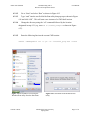
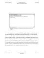
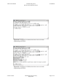
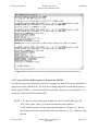
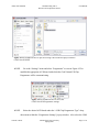
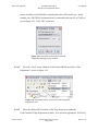
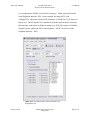
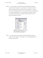
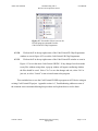
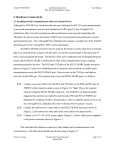
Atmel AVR STK500
Communicating with a
Host PC and Temperature Sensor
User Manual
4. Application Programming
4.2 Uploading an Application (Programming the Board)
It is important to remember that the target microcontroller installed on the STK500 is what is
actually being programmed. Only HEX file programs can be uploaded to the flash memory of
the target MCU, and only HEX or ROM file programs can be uploaded to the EEPROM memory
of the target MCU. The flash memory of AVR microcontrollers is typically what is programmed
because of its available space and relatively unlimited read and write life cycles. EEPROM
memory has a limited write life cycle so only programs that will be used frequently and remain
relatively unchanged are reserved for EEPROM [10]. This project focuses on the use of the flash
memory only.
The STK500 PCB has a specific RS-232 communication protocol that requires data to be
received for in-system programming using eight data bits, one stop bit, and no parity at 115.2
kbps (i.e. at a rate of 115200 baud) [14]. The following subsections describe two ways of using
this protocol to upload an application to an STK500 board.
4.2.1 Using a Command Line Utility to Program the STK500
The microcontroller installed on an STK500 can be programmed using the Windows command
line utility (CMD). The CMD session must be in the same directory as the “Stk500.exe”
program, which is located in “C:\Program Files\Atmel\AVR Tools\STK500” when AVR Studio
is installed in its default directory. The Stk500.exe program is an STK500 DOS programmer
provided by Atmel. It can be copied and pasted to any desired location after AVR Studio is
installed. The HEX file that will be programmed to the board must either be in the same location
as the Stk500.exe program or its directory must be provided in the command line used to
program the board (the preceding option is recommended and is used for the sample DAQ
project provided in this document). Any pre-existing HEX file can have its name changed
without it losing its functionality.
A list of all applicable commands is given in the STK500 User Guide [1]. Being able to
use CMD allows for a batch file (.bat) to be created that automatically programs the board when
the file is opened. A batch file is simply a text file that contains CMD commands that will be
executed line-by-line within a CMD session as soon as the file is opened. The batch file given in
Vincent A. Rosa
Florida Gulf Coast University
Spring 2009
Page 1 of 11
Atmel AVR STK500
Communicating with a
Host PC and Temperature Sensor
User Manual
Appendix section A.2.2.3 provides an example of how the command utility can be used to
program the STK500. The following list of commands and how they are used accompany the
instructions that provided an example of how to use the CMD to program an ATmega8515L
MCU when it is installed in a target socket on an STK500. Before performing the following
instructions, be sure to establish the hardware setup described in the Hardware Connectivity
section 2.1 and then power on the board using the switch shown in Figure 2.3. The
Troubleshooting section of the appendix (section A.3) provides some common techniques used
to be sure the board is properly powered on and is ready to be used.
Commands Summary:
[-d device_name] [-m programming_mode] [-e optional_memory_device]
[-p memory_device] [-v memory_device] [-if HEX_file] [-c com_port]
Executed Commands:
-dATmega8515
==> get the protocols to program the Atmega8515
-ms
==> serial programming mode
-e
==> erase all memory devices before programming
-pf
==> program the flash memory
-vf
==> verify the flash memory
-ifstk500_prog.hex
==> use the HEX file "stk500_prog.hex" to program the flash
-ccom4
==> use com4 as the communication port
4.2.1.1
Copy and paste both the “Stk500.exe” program and the desired HEX file into a
designated location, which is “C:\stk500_example” for this procedure. Create this
directory if it does not exist. CodeVisionAVR stores the HEX file built from an
application in a folder labeled “Exe” within the directory assigned for this
application. Use the HEX file located in
“C:\stk500_example\STK500_TestProg\Exe” created from section 4.1.1 to better
follow this example. Copy and paste this file into “C:\stk500_example” and rename
the pasted file to “stk500_prog.hex”.
Vincent A. Rosa
Florida Gulf Coast University
Spring 2009
Page 2 of 11
Atmel AVR STK500
Communicating with a
Host PC and Temperature Sensor
User Manual
4.2.1.2
Go to “Start” and select “Run” as shown in Figure 4.15
4.2.1.3
Type “cmd” into the text field of the Run utility that pops up as shown in Figure
4.16 and click “OK”. This will start a new instance of a CMD shell session.
4.2.1.4
Change the directory using the “cd” command followed by the location
designated in step 4.2.1 (e.g. enter cd C:\stk500_example as shown in Figure
4.17).
4.2.1.5
Enter the following line into the current CMD session:
stk500 -dATmega8515 -ms -e -pf -vf -ifstk500_prog.hex -ccom4
Figure 4.15 Screenshot of accessing the
Windows Run utility from the Start menu.
Vincent A. Rosa
Figure 4.16 Screenshot of the Windows Run
utility.
Florida Gulf Coast University
Spring 2009
Page 3 of 11
Atmel AVR STK500
Communicating with a
Host PC and Temperature Sensor
User Manual
Figure 4.17 Screenshot of a CMD session where the directory has been
changed.
This concludes how to program the STK500 using the Windows command line utility.
The error shown in Figure 4.18 will appear if the board is not powered on or has an incorrect
hardware setup. If this is the case, be sure the board is powered on and is set up as directed in
section 2.1 of this document. The error shown in Figure 4.19 will appear if the referenced HEX
file is not within the specified location. Simply correct this by referencing the correct location or
by adding the referenced HEX file into the same location as the Stk500.exe program. Figure
4.20 shows the board was successfully programmed after fixing the two previously listed errors.
Appendix section A.3, Troubleshooting, addresses some of the common errors encountered in
this section and provide some techniques on how to resolve them.
Vincent A. Rosa
Florida Gulf Coast University
Spring 2009
Page 4 of 11
Atmel AVR STK500
Communicating with a
Host PC and Temperature Sensor
User Manual
Figure 4.18 Screenshot of a CMD session where an error occurred
programming an STK500.
Figure 4.19 Screenshot of a CMD session where an error occurred
programming an STK500.
Vincent A. Rosa
Florida Gulf Coast University
Spring 2009
Page 5 of 11
Atmel AVR STK500
Communicating with a
Host PC and Temperature Sensor
User Manual
Figure 4.20 Screenshot of a CMD session where programming an STK500 was successful.
4.2.2 Using CodeVisionAVR Evaluation to Program the STK500
The following procedure instructs the user how to program one of the AVR devices installed in a
target socket on the STK500 PCB. The AVR device being programmed within this procedure is
the ATmega8515L MCU. If CodeVisionAVR is not already opened, refer to instruction 4.1.1.1
to open the CodeVisionAVR Evaluation IDE.
4.2.2.1
If a project is not already opened within the CodeVisionAVR IDE, go to the
“File” menu, select “Open”, go to the desired directory that contains a
CodeVisionAVR project file (.prj), and open this project as in Figure 4.21. Be sure
that all project files have already been built as in instruction 4.1.1.12. Otherwise, skip
this step.
Vincent A. Rosa
Florida Gulf Coast University
Spring 2009
Page 6 of 11
Atmel AVR STK500
Communicating with a
Host PC and Temperature Sensor
User Manual
Figure 4.21 Screenshot of how to open an existing CodeVisionAVR project from the
CodeVisionAVR IDE.
4.2.2.2
Go to the “Settings” menu and select “Programmer” as seen in Figure 4.22 to
establish the appropriate AVR board with which the CodeVisionAVR Chip
Programmer will be communicating.
Figure 4.23 Screenshot of how to access the
CodeVisionAVR Programmer settings.
4.2.2.3
Select the desired AVR board under the “AVR Chip Programmer Type” dropdown menu within the “Programmer Settings” pop-up window. Also select the COM
Vincent A. Rosa
Florida Gulf Coast University
Spring 2009
Page 7 of 11
Atmel AVR STK500
Communicating with a
Host PC and Temperature Sensor
User Manual
port to which the serial/USB cable is attached from the AVR board in use. In this
example, an AVR STK500 evaluation board is connected to the host PC at COM3 as
seen in Figure 4.23. Click “OK” to proceed.
Figure 4.23 Screenshot of the CodeVisionAVR
Programmer Settings pop-up window.
4.2.2.4
Go to the “Tools” menu within the CodeVisionAVR IDE and select “Chip
Programmer” as seen in Figure 4.24.
Figure 4.24 Screenshot of how to access the CodeVisionAVR
Programmer tool.
4.2.2.5
Select the desired MCU from the “Chip” drop-down menu within the
CodeVisionAVR Chip Programmer window. Also select the appropriate “SCK Freq”
Vincent A. Rosa
Florida Gulf Coast University
Spring 2009
Page 8 of 11
Atmel AVR STK500
Communicating with a
Host PC and Temperature Sensor
User Manual
(i.e. the appropriate SPI Bus “Serial Clock Frequency”, which is the speed for the
Serial Peripheral Interface, SPI). In this example, the target MCU is the
ATmega8515L, which has a default SCK frequency of 230400 Hz [15] as shown in
Figure 4.25. The ATmega8515(L) Datasheet [4] further explains how to calculate
this frequency with respect to different settings (e.g. SCK with respect to Oscillator
Frequency in the subsection “SPI Control Register – SPCR” of section “Serial
Peripheral Interface – SPI”).
Figure 4.25 Screenshot of the CodeVisionAVR Chip
Programmer tool.
Vincent A. Rosa
Florida Gulf Coast University
Spring 2009
Page 9 of 11
Atmel AVR STK500
4.2.2.6
Communicating with a
Host PC and Temperature Sensor
User Manual
Go to the “Program” menu within the CodeVisionAVR Chip Programmer
window and select “Erase Chip” as seen in Figure 4.26. This will erase the flash
memory of the target AVR device (in this case, the ATmega8515L). It is good
practice in AVR development to always erase the target memory before programming
it. Sometimes erasing the memory is a required action to ensure data consistency
between the amount of utilized (i.e. programmed) memory and the size of the
program being uploaded to memory.
Figure 4.26 Screenshot of how to access the
Erase Chip program command from the
CodeVisionAVR Chip Programmer.
4.2.2.7
Go to the “Program” menu within the CodeVisionAVR Chip Programmer
window and select “FLASH” as seen in Figure 4.27. This will program the flash
memory of the target MCU.
Vincent A. Rosa
Florida Gulf Coast University
Spring 2009
Page 10 of 11
Atmel AVR STK500
Communicating with a
Host PC and Temperature Sensor
User Manual
Figure 4.27 Screenshot of how to access the
FLASH program command from the
CodeVisionAVR Chip Programmer
4.2.2.8
Click on the X in the top-right corner of the CodeVisionAVR Chip Programmer
window as seen in Figure 4.25 to exit the CodeVisionAVR Chip Programmer.
4.2.2.9
Click on the X in the top-right corner of the CodeVisionAVR window as seen in
Figure 4.13 to exit the entire CodeVisionAVR IDE. If any changes have been made
to any files without saving them, a pop-up window will appear confirming whether
the files should be saved. Select “Yes” to save the changes and exit, select “No” to
just exit, or select “Cancel” to not exit and return to the program.
This concludes how to use the CodeVisionAVR IDE to program an AVR device using an
existing CodeVisionAVR project. Appendix section A.3, Troubleshooting, addresses some of
the common errors encountered during this procedure and explains how to resolve them.
Vincent A. Rosa
Florida Gulf Coast University
Spring 2009
Page 11 of 11