1
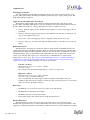
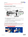
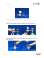
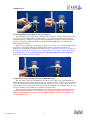
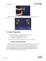
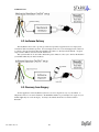
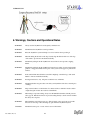
Patents Pending User Manual STARR Life Sciences Corp. 333 Allegheny Avenue, Suite 300 Oakmont, PA 15139 © STARR Life Sciences Corp., 2011 P/N 100536, Rev 2.0 USER MANUAL Table of Contents 1. INTRODUCTION AND GENERAL SYSTEM LAYOUT ....................................................................1 2. OXYDIAL™ PACKAGED PARTS.........................................................................................................1 3. SYSTEM REQUIREMENTS AND DETAILED DESCRIPTION .......................................................1 3.1. BASIC OXYDIAL™ SYSTEM SPECIFICATIONS .......................................................................................1 3.2. OXYDIAL™ REGULATORS ....................................................................................................................2 3.3. OXYDIAL™ GAS BLENDER ..................................................................................................................2 3.4. OXYDIAL™ FLOW METER....................................................................................................................4 3.5. OXYDIAL™ HUMIDIFIER CHAMBER AND OUTLET HOSE ......................................................................4 4. SETTING UP THE OXYDIAL™ SYSTEM...........................................................................................5 5. OXYDIAL™ APPLICATIONS ..............................................................................................................9 5.1. MECHANICAL VENTILATION ASSIST......................................................................................................9 5.2. ISOFLURANE DELIVERY ......................................................................................................................10 5.3. RECOVERY FROM SURGERY ................................................................................................................10 6. WARNINGS, CAUTIONS AND OPERATIONAL NOTES ...............................................................11 7. REPLACEMENT PARTS, ACCESSORIES AND TECHNICAL SUPPORT ..................................12 8. INTELLECTUAL PROPERTY PROTECTING THE OXYDIAL™ ................................................12 9. WARRANTIES AND LIABILITIES.....................................................................................................13 P/N 100536, Rev. 2.0 i USER MANUAL 1. Introduction and General System Layout Thank you for purchasing the OxyDial™ from STARR Life Sciences®. The OxyDial™ is the easiest device available that will allow you to quickly adjust fractional oxygen delivered to your animals. We hope that you will be completely satisfied with the system. A basic schematic of the OxyDial™ system is given below. OxyDial™ Blender N2 Regulator O2 Flow Meter N2 Hi-Press Hose (20 ft) O2 Hi-Press Hose (5 ft) OR Humidifier w/ Safety Popoff O2 Regulator O2 Hi-Press Hose (20 ft) 2. OxyDial™ Packaged Parts The following is a list of parts that should be included in your OxyDial™ shipping box: • OxyDial™ Blender • Nitrogen Pressure Regulator (50 psig preset, CGA 580 inlet fitting) • Oxygen Pressure Regulator (50 psig preset, CGA 540 inlet fitting) • Nitrogen Supply Hose (20 ft, black) • Oxygen Supply Hose (20 ft, green) • Flowmeter (Rotameter) • Humidifier Chamber with Pressure Safety Popoff • High-Pressure Outlet Hose (5 ft, green) • Tripod Stand with Blender Mount • OxyDial™ User Manual Please check to see that you have all of these parts. If you find any part missing, please contact STARR Life Sciences at 1-866-9STARR9 ext. 9, or by e-mail at [email protected]. 3. System Requirements and Detailed Description 3.1. Basic OxyDial™ System Specifications Product Description: The OxyDial™ is a product that allows you to quickly and easily dial oxygen fraction (FIO2) in O2/N2 gas mixtures between 0 and 100%. Using universal fittings, the system connects to centralized supplies (bottles P/N 100536, Rev. 2.0 1 USER MANUAL or wall outlets) of oxygen and nitrogen. The user simply turns a dial to set the oxygen percentage, and can adjust the outlet flow rate to obtain a constant stream of gas at the desired FIO2 and flow rate. The system is purely mechanical and uses no electrical power. All hoses and fittings to connect from the bottled gas source to the OxyDial™ system are provided. FIO2 Range: 0 to 100% Outlet Flow Rate Range: 0 to 15 L/min [O2/N2] Note: You can open the flow valve beyond the indicated maximum flow of 15 L/min to provide an actual maximum flush flow of ~30 L/min. Bottle/Tank Input Gases: Oxygen with Standard CGA 540 Fitting Nitrogen with Standard CGA 580 Fitting System Input Gas Pressure: Up to 1500 psi (10.3 MPa) with gas tanks OR 50 ± 10 psi (345 ± 70 kPa) to blender USE ONLY THE PARTS THAT COME WITH YOUR OxyDial™ SYSTEM !! DO NOT SUBSTITUTE ANY PARTS !! 3.2. OxyDial™ Regulators The pressure regulators that are provided with your OxyDial™, and that attach to the supply gas sources, are preset to 50 psig. DO NOT tamper with these regulators as the presetting allows your system to operate safely and accurately. The regulators do not need any specific maintenance, although we recommend that you use clean gas sources that do not contain rust, water or other particulate matter. 3.3. OxyDial™ Gas Blender The gas blender is the heart of the OxyDial™. Although it is a purely passive, mechanical device, it is important that you understand its basic operation and maintenance requirements. Important details regarding these issues are provided below. Gas Mixture Accuracy If there is sufficient flow through the blender (see details in Outlet Delivery Ports section below), the blender will be accurate to ±3% of reading. To assure accuracy, some other considerations are germane: • If better accuracy is desired, we recommend that you compare the FIO2 at your dial setting with that from an oxygen analyzer. • Use only clean, dry, medical-grade supply gases. • Always allow sufficient time for equilibration of the gas mixture at your downstream delivery point after adjusting the FIO2. The equilibration time is dependent on the volume of tubing/hose and other parts connected to the blender. P/N 100536, Rev. 2.0 2 USER MANUAL Inlet/Supply Gas Pressure The oxygen and nitrogen inlet/supply pressures must be 50 psig in order for the flow meter to work properly. The regulators that come with your OxyDial™ system are preset to 50 psig outlet pressure. DO NOT tamper with these regulators. Supply Gas Pressure Differential – Reed Alarm The blender is equipped with a passive alarm (reed alarm) that will indicate when the gas supply pressures differ. The alarm, which has the sound of a loud whistle, will activate whenever the two inlet gas pressures differ by more than 15 - 20 psig. The alarm can sound for a number of reasons: • Startup - If the gas supplies are not simultaneously pressurized, or if only one gas supply source is pressurized • Shutdown - If the gas supply pressures bleed down at different rates when they are turned off, or if only one of the supplies was closed • Depleted Gas - One of the supply gas sources is depleting, causing its pressure to drop • Regulator Tampering - If someone has tampered with the regulators so that they are not both set at 50 psig Outlet Delivery Ports The blender has 2 outlet delivery ports labeled “Outlet no bleed Accurate 3-30 LPM” (left side) and “Outlet w/bleed Accurate 0-30 LPM” (right side). Both ports deliver the same blended gas, but they differ slightly in function. This is because the blender dial face is only accurate if there is sufficient flow passing through the blender. One port automatically bleeds a sufficient bypass flow to achieve this accuracy (the “bleed” port), while the other requires you to select flows above a minimum flow to obtain accurate mixtures (the “no bleed” port). The “bleed” port will automatically vent 2.5 to 3.5 L/min of blended gas continuously out of the bottom of the blender whenever you connect a device to that port and your gas supplies are pressurized. Detailed descriptions of each are provided here. Left Side – No Bleed Minimum Required User-Selected Flow - 3 L/min Gas Vented – none Notes: All gas leaves the blender through this port, so there is no bypass flow. Right Side – w/Bleed Minimum Required User-Selected Flow - 0 L/min Gas Vented – up to 3.5 L/min continuously Notes: You must shut off your gas supplies when not using the system AND you have the flowmeter connected to this port. There is a check valve that opens the bypass flow to be activated when you connect to the fitting on this port. Other Notes • DO NOT tape over or block any of the ports on the bottom of the blender. • DO NOT immerse the blender in any liquids. • DO NOT steam clean or autoclave the blender. • Clean surfaces using a 10% bleach solution or light detergent in water. Blender Maintenance The blender functions using various elastomeric components such as seals and O-rings. These materials will degrade and/or wear over time commensurate with your level of usage and cleanliness of the supply gases, resulting in degradation of performance (reduction in accuracy). These materials are designed P/N 100536, Rev. 2.0 3 USER MANUAL to function for a minimum of 2 years, but will eventually need to be replaced. A service life of 3 years should be considered maximum, even under the best conditions. To have your blender serviced, please contact STARR Life Sciences at: 1-866-978-2779 ext. 5, or [email protected]. 3.4. OxyDial™ Flow Meter The flow meter is a type of variable area meter known as a rotameter. It has a tiny ball that floats via drag from the gas as it passes through the barrel. The indicated flow is specified from the vertical center of the ball. Because of the nature of this flow meter, it is important that the rotameter be oriented vertically in order to allow you to read it accurately. This particular rotameter is calibrated for oxygen, so if flow measurement accuracy is desired, we provide an expression to allow you to correct for the difference when not delivering 100% FIO2. It can be shown that the actual flow is related to the flow on the rotameter barrel by the following expression: FI Qactual = Qrotameter 0.875 + 0.125 O2 , 100 where Qactual is the true volume flow rate (L/min), Qrotameter is the volume flow rate read from the rotameter barrel (L/min) and FIO is the oxygen fraction indicated on the blender dial face (%). 2 Of course, you can also invert this equation to calculate the rotameter flow that you would set based on a desired actual flow. We have Qrotameter = Qactual FIO 0.875 + 0.125 2 100 . 3.5. OxyDial™ Humidifier Chamber and Outlet Hose The OxyDial™ System comes equipped with 2 types of outlet connections. The first is a high-pressure oxygen hose that connects directly from the flow meter to a device that has an O2 DISS (Diameter Index Safety System) connector and that permits pressures up to 50 psi, such as an isoflurane dispenser. This hose and any device that it can connect to that has the appropriate DISS fitting are rated for this pressure. You must assume that other hose connections are NOT rated for this pressure, and you should use caution in connecting to this system using such devices. The issue is that if flow passing through whatever is attached to the flow meter is blocked, the pressure inside the attached material will reach 50 psi, causing a potential safety hazard. To accommodate the use of the OxyDial™ with devices not properly rated for high pressure, we provide a second connection option – the humidifier chamber, which also connects directly to the outlet of the flow meter. It has a hose barb port that accommodates tubing from 1/8 to 1/4 inch (3.18 to 6.35 mm) ID. In addition to allowing you to humidify the gas if you choose, it more importantly has a safety feature to prevent the downstream pressure from becoming excessive. The humidifier chamber is equipped with a pressure safety popoff valve that allows the gas to vent if the pressure exceeds a threshold of 3 psi. P/N 100536, Rev. 2.0 4 USER MANUAL Thus, you MUST use the humidifier chamber if the system that you are connecting to cannot accommodate the high-pressure outlet hose. 4. Setting Up the OxyDial™ System Instructions for setting up the OxyDial™ System are described here. Please refer to this schematic for assembly of the OxyDial™ System. N2 Regulator (50 psi preset) Inlet - CGA-580 N2 Hi-Press Hose (black) Outlet - DISS BA N2 Inlet – DISS N/N N 2 Outlet - DISS N/N N2 O2 Flow Meter Inlet – DISS N/N O2 Outlet - DISS BA O2 OxyDial™ Blender N2 Inlet – DISS BA N2 O2 Inlet – DISS N/N O2 Outlet - DISS BA O2 O2 Hi-Press Hose (3 ft, green) Inlet – DISS N/N O2 Outlet - DISS N/N O2 N2 O2 User-Supplied O2 Hi-Press Hose (green) Inlet – DISS N/N O2 Outlet - DISS BA O2 Humidifier w/ Safety Popoff Inlet – DISS N/N O2 Outlet – tube opening O2 Regulator (50 psi preset) Inlet - CGA-540 Outlet - DISS BA O2 OR The following definitions are applicable to the schematic: CGA – Compressed Gas Association – Standard fittings for high-pressure gas tanks. Each gas type has its own designated number. DISS – Diameter Index Safety System – Standard set of high-pressure gas fittings designed specifically to prevent inadvertent errors in mechanical connections with medical grade gases. BA – Body Adaptor – The “male” half of a DISS fitting. N/N – Nut/Nipple – The “female” half of a DISS fitting. 1] Connect the Oxygen and Nitrogen Regulators to the Gas Tanks The OxyDial™ comes with two regulators (oxygen and nitrogen) that are preset to 50 psi. DO NOT ADJUST this pressure by turning any knobs on the top of the regulators. The regulators are outfitted with standard Compressed Gas Association (CGA) fittings that will allow them to be connected to their respective tanks. Each regulator should be tightened with a wrench. To replace any of the gas tanks after the gas has been depleted, you should close the valve on top of the tank, then remove the regulator at the CGA fitting! P/N 100536, Rev. 2.0 5 USER MANUAL Note that the oxygen regulator has a cap on the inlet side. To remove this, simply pull the sleeve toward the regulator body, and it should pop off (see figure below). sleeve cap 2] Connect the Supply Hoses to the Regulators The oxygen and nitrogen regulators have special connecting hoses. The oxygen hose is green and the nitrogen hose is black, and the fittings on each are of the DISS type, and therefore cannot be interconnected with each other. Either end of the nitrogen hose can be connected to the nitrogen regulator, but the oxygen hose has different fittings on each end, only one of which will fit on the oxygen regulator. Simply handtighten the end of the hose that fits on the regulator outlet fitting. It is not necessary to use a wrench. 3] Attach the Hoses to the OxyDial™ Blender Lay the blender upside down on a surface, and attach the other ends of each of the hoses to the appropriate connection on the bottom of the blender. In the correct orientation, the nitrogen inlet will be on the left bottom side of the blender, while the oxygen inlet will be on the right bottom side. Again, the hoses cannot be interchanged. P/N 100536, Rev. 2.0 6 USER MANUAL Because of the type of fittings used on the oxygen side, you will have to hand-tighten the fittings together, then use 2 wrenches to snug them up as shown below. 4] Mount the OxyDial™ Blender on the Stand Remove the tripod stand from its box, and retract the legs. Before mounting the blender on the stand, make sure that the bracket on the top of the stand is facing one of the three legs as shown below. This orientation will help to prevent the system from tipping. Next, place the assembled blender in the bracket on the top of the stand. 5] Attach the Flow Meter Attach the flow meter to either of the outlet ports on the sides of the blender. Be sure to choose the correct port for your application (see “Outlet Delivery Ports” in Section 3.3 above). Once attached, the fitting should be tightened gently with a wrench. Make sure that the flow meter is in a vertical position so that its reading will be as accurate as possible. P/N 100536, Rev. 2.0 7 USER MANUAL 6a] Attach the High Pressure Outlet Connection (5 ft Hose) Your OxyDial™ comes equipped with 2 different outlet connections. The first outlet connection is a 5 foot (1.5 m) section of high pressure hose that will allow you to connect the OxyDial ™ directly to an isoflurane dispenser or other device equipped with an oxygen DISS body adaptor, and that can handle pressures above 50 psi. This particular hose is equipped with hand-tight nuts, so it is unnecessary to tighten them with a wrench. This hose can be connected to the flow meter outlet, but you can also opt to connect this high pressure hose directly to the blender without passing through the flow meter, as shown in the figure below. Instructions for attaching the flow meter are provided just above. Note that if you choose to leave the flow meter in place, and the device to which you are connecting also has a flow meter or other user-adjustable flow-limiting orifice, you should open the flow valve on the HypoxyDial™ flow meter all the way to reduce its flow restriction as much as possible. 6b] Attach the Low Pressure Outlet Connection (Humidifier Bowl) The other outlet connection is a humidifier bowl with a pressure safety popoff. This humidifier is a bubble-through type, and it connects directly to the bottom of the flow meter. It has an outlet hose barb that can accommodate tubing between 1/8 and 1/4 inch inner diameter to connect to other devices. The bowl should be filled and operated with the water level between the “minimum” and “maximum” lines. If you do not want to humidify, you can simply use the chamber completely empty. The most important feature of the humidifier however, is the pressure safety popoff, which vents the system when pressures inside the bowl exceed 3 psi. Because of its overpressure safety utility, you MUST use the humidifier bowl when connecting the HypoxyDial™ System to devices that are not rated for high pressure! P/N 100536, Rev. 2.0 8 USER MANUAL Pictures of the fully assembled system are shown below, with the flow meter located on either outlet of the blender. 5. OxyDial™ Applications The OxyDial™ can be used in a large number of applications, which include: • Provide FIO2 control during mechanical ventilation. • Provide FIO2 control during isoflurane anesthesia delivery. • Provide FIO2 control during recovery from surgery. Details on how to implement these OxyDial™ applications are given in the sections below. 5.1. Mechanical Ventilation Assist The OxyDial™ System can be used to provide gas with user-specified oxygen fraction to a mechanical ventilator. A basic functional configuration is shown in the figure below. The OxyDial™ should be connected to the location on the ventilator where it receives its inlet gas. If the ventilator cannot accommodate the high-pressure outlet hose, you must use tubing in conjunction with the humidifier, as shown below. If the ventilator requires dry gas, you can simply not fill the humidifier bowl, but you still need to use the humidifier because of its overpressure safety feature, unless the connection has a vent or blow-by so that high pressure cannot build up in the low pressure line. P/N 100536, Rev. 2.0 9 USER MANUAL 5.2. Isoflurane Delivery The OxyDial™ can be used to provide gas with a user-specified oxygen fraction to be employed in conjunction with an isoflurane vaporizer. You can simply use the 5 foot (152 cm) high pressure outlet hose to connect to the vaporizer from either the OxyDial™ flow meter, or directly from the blender. A typical setup would be similar to that shown in the sketch below. This system should also be used with a MouseOx® pulse oximeter to allow you to monitor the health of your animals while they are under anesthesia. 5.3. Recovery from Surgery Another application of the OxyDial™ System is to use it for surgical recovery of your animals. A simple tube and nose cone can be attached to the humidifier chamber to provide improved oxygen for your animals while they recover from surgery. As always, the animals should also be monitored with a MouseOx®. P/N 100536, Rev. 2.0 10 USER MANUAL 6. Warnings, Cautions and Operational Notes WARNING Always use the OxyDial™ in an adequately ventilated area. WARNING DO NOT use the OxyDial™ around open flame. WARNING Place the OxyDial™ system with tripod on a level surface when operating it. WARNING When mounting the blender on the tripod stand, align the blender with one of the legs of the stand to provide more mechanical stability. WARNING DO NOT lay tubing from the OxyDial™ in areas where it can represent a tripping hazard. WARNING DO NOT lay tubing from the OxyDial™ System in areas where it can be inadvertently grabbed or snagged such that heavier parts of the system can be tipped or pulled from surfaces. WARNING If the stand with mounted blender seems like it might tip, extend the legs of the stand further to increase mechanical stability. WARNING Investigational device only. All parts are NOT for use on humans. WARNING DO NOT substitute any parts that come with your OxyDial™ with other, external parts or fittings. WARNING Wipe external surfaces of the blender, flow meter and hoses with 10% bleach solution or light detergent in water after each use with animals. WARNING When using low pressure tubing, always use the humidifier chamber with the pressure safety popoff. DO NOT connect low-pressure tubing directly to the flow meter without this safety valve in place. WARNING The OxyDial™ uses high pressure gas. Shut all supply valves and vent gas from the lines before removing or disconnecting any parts from the OxyDial™ System. CAUTION DO NOT obstruct ports or vents on the bottom of the blender. P/N 100536, Rev. 2.0 11 USER MANUAL CAUTION Condensed water in the gas supplies can cause malfunction of this device. Use only clean, dry, medical-grade gases with the OxyDial™. CAUTION Always disconnect the gas sources from the blender when the blender is not in use. OPERATIONAL NOTE We recommend that you use an Oxigraf O2-Cap Oxygen Analyzer or equivalent analyzer to verify FIO2 and FICO2. 7. Replacement Parts, Accessories and Technical Support The following are adjunct or replacement parts for the OxyDial™: OxyDial™ Replacement Parts #100513 N2 Regulator #100514 O2 Regulator #100527 N2 Connection Hose 20ft Black #100528 O2 Connection Hose 20ft Green #100517 Blender Stand #100519 Flow Meter #100535 High-Pressure Outlet Hose 5ft Green #100520 Humidifier Accessory Devices #000001 MouseOx® Control Box #000501 OxyDial™ #000503 HypoxyDial™ STARR Life Sciences® values its customers and is dedicated to providing quality products and solutions to meet your needs. If you have any questions, or you need ANY replacement parts, please call or email STARR Life Sciences at: 1-866-978-2779 ext. 5, or [email protected]. 8. Intellectual Property Protecting the OxyDial™ © 2005-2011 STARR Life Sciences® Corp, All rights reserved. STARR Life Sciences, the STARR Life Sciences logo and other STARR Life Sciences marks are owned by STARR Life Sciences and may be registered. STARR Life Sciences, the STARR Life Sciences logo and other STARR Life Sciences marks are owned by STARR Life Sciences Corporation and may not be used without express written permission of STARR Life Sciences Corporation. Technology Warning: US and foreign patents are pending. Unauthorized reproduction or distribution of this OxyDial™ system, or certain portions of it, will result in civil and criminal penalties, and will be prosecuted to the fullest extent possible under the law. P/N 100536, Rev. 2.0 12 USER MANUAL 9. Warranties and Liabilities Limited Warranty & Disclaimer STARR Life Sciences® (“SLS”) warrants its non-disposable hardware and sensors (the “Nondisposable Products”) against defects in material, workmanship, and performance for a period of one (1) year from the date of shipment by SLS (the “Warranty Period”). SLS warrants that the Non-disposable Products will meet the electronic and mechanical specifications stated in the SLS user manual, although the specifications are subject to change without notice. SLS, at its option, will repair or replace a Nondisposable Product that is found to be defective during the Warranty Period. Defective Non-disposable Products must be received at STARR Life Sciences Corp., 333 Allegheny Ave., Suite 300, Oakmont, PA 15139 no more than thirteen (13) months from the original date of shipment by SLS. All shipments must include a Return Authorization Number (RMA #), obtainable from SLS, and must be sent freight prepaid by the sender. This warranty is nontransferable. This warranty does not apply to any defects or damages caused by an animal or resulting from alteration, modification, neglect, misuse, usage of improper power sources, damage in transportation, abuse, or any cause other than normal use of the Non-disposable Products. This warranty does not apply to products resold by SLS that are manufactured by other companies. No warranty or claim is made by SLS, regarding the efficacy of any product for any particular application. Except for the Limited Warranty expressly set forth above, SLS MAKES NO WARRANTIES WHATSOEVER. SLS HEREBY DISCLAIMS ALL WARRANTIES, EXPRESS OR IMPLIED, ORAL OR WRITTEN, INCLUDING, WITHOUT LIMITATION, ANY IMPLIED WARRANTIES OF MERCHANTABILITY OR FITNESS FOR A PARTICULAR PURPOSE, OR ANY IMPLIED WARRANTIES ARISING FROM ANY COURSE OF DEALING, USAGE, OR TRADE PRACTICE. In no event, shall SLS be liable for any damages whatsoever arising out of the use of its product, including without limitation any direct, incidental or consequential damages, any damages for loss of profits, business interruption, loss of information or any pecuniary loss even if SLS has been advised of the possibility of such damages. Important Notice SLS products are designed to be used while under the supervision of research scientists in an experimental application. All items sold by SLS are for NON-HUMAN use. The user is solely responsible for determining the suitability of any items from SLS for their particular application. ALL SOFTWARE, MANUALS, COMMUNICATIONS, ETC. WILL BE IN THE ENGLISH LANGUAGE ONLY. P/N 100536, Rev. 2.0 13


![User Manual [PDF 1.83MB]](http://vs1.manualzilla.com/store/data/005708072_1-847484e89010f626b2bba7bc797371fb-150x150.png)