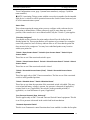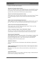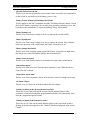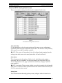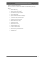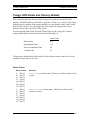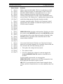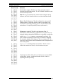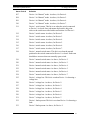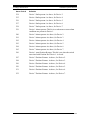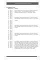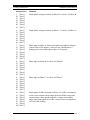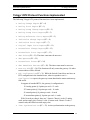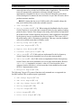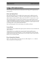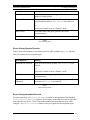
1
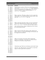
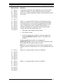
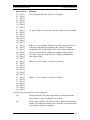
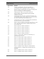
EnergyLine 5801-SC IntelliTEAM Gateway for Telegyr 8979 Protocol Supplement October 23, 2003 S&C Electric Company Automation Systems Division 1042-563A / 10-23-03 EnergyLine 5801-SC IntelliTEAM Gateway for Telegyr 8979 Protocol S&C Electric Company Automation Systems Division Proprietary Notice This document contains information which is proprietary to S&C Electric Company and is provided under the terms and conditions of a Purchase Order Terms and Conditions Agreement between S&C Electric Company and each of its customers. Disclosure of information contained in this document to third parties without prior written permission from S&C Electric Company is strictly forbidden. Information in this document is subject to change without notice and does not represent a commitment on the part of the vendor. Copyright 2003 S&C Electric Company. All Rights Reserved. Printed in the USA The EnergyLine logo and IntelliTEAM are registered trademarks of S&C Electric Company. Hayes is a trademark of Hayes Microcomputer Products, Inc. UtiliNet is a registered trademark of Schlumberger, Inc. All other trademarks are the property of their respective holders. S&C Electric Company 1135 Atlantic Avenue, Alameda, CA 94501, USA Tel (510) 864-6850/ FAX (510) 864-6860 2 1042-563A / 10-23-03 S&C Electric Company Automation Systems Division EnergyLine 5801-SC IntelliTEAM Gateway for Telegyr 8979 Protocol Contents Introduction_____________________________________________________________5 Applicable Software ____________________________________________________5 Manual Conventions ____________________________________________________6 Cautions______________________________________________________________6 Gateway Setup Screens____________________________________________________7 View the Second SETUP: Communications Screen ____________________________7 View the Third SETUP: Communications Screen _____________________________9 View the Fourth SETUP: Communications Screen ___________________________11 Telegyr Points Setup Screens ______________________________________________14 View the SETUP: Status Points Screen ____________________________________14 View the SETUP: Analog Points Screen ___________________________________18 View the SETUP: Control Points Screen ___________________________________19 Gateway Troubleshooting Screen___________________________________________22 Telegyr 8979 Points List (Factory Default) ___________________________________24 Status Points _________________________________________________________24 Analog Input Points____________________________________________________33 Pulse Accumulator Points _______________________________________________36 Control Points ________________________________________________________37 Telegyr 8979 Protocol Functions Implemented ________________________________39 Telegyr 8979 Implementation______________________________________________42 Status and Analog Points________________________________________________42 Control Points ________________________________________________________42 Errors During Select Function____________________________________________42 Errors During Operate Function __________________________________________43 Errors During Immediate Execute_________________________________________43 Local Control Point Operation Process_____________________________________44 Remote Control Point Operation Process ___________________________________44 Remote/Local ________________________________________________________45 1042-563A / 10-23-03 3 EnergyLine 5801-SC IntelliTEAM Gateway for Telegyr 8979 Protocol S&C Electric Company Automation Systems Division Notes: 4 1042-563A / 10-23-03 S&C Electric Company Automation Systems Division EnergyLine 5801-SC IntelliTEAM Gateway for Telegyr 8979 Protocol Introduction This document describes the S&C Electric Company EnergyLine Model 5801-SC IntelliTEAM® Gateway for Landis & Gyr Telegyr 8979 protocol. The gateway lets a SCADA master station that uses Telegyr 8979 protocol communicate with a team of Switch Controls that use DNP protocol. The gateway maintains a database with information about each Switch Control and about team-related parameters, and it updates the records at regular intervals. The master station can control or receive information about each team member via the gateway. It can also receive information about the overall team status. When the gateway receives a request for information, it responds with the data in its database. (The information for a single Switch Control and for the team database are collected independently. At any given moment, the entries may not be synchronized.) When the gateway receives an operate command for another (remote) Switch Control, it accepts or rejects the packet based on the information in its database. It then creates a matching DNP packet to pass along. The gateway has two communications ports: Port A for Telegyr 8979 protocol, and Port B for DNP protocol. Each port can be connected to a variety of communications hardware (such as a radio, modem, or fiber optic transceiver). They can also be directly connected to another communicating device (such as another team Switch Control). For more information about the setup and operation of IntelliTEAM Switch Controls, see the User’s Manual. Applicable Software This document was prepared for use with software version SNCD2A4X, Rev. 2.25, and PADD2A4X, Rev. 2.26. For questions regarding the applicability of information in this document to future software releases, please contact S&C Electric Company. 1042-563A / 10-23-03 5 EnergyLine 5801-SC IntelliTEAM Gateway for Telegyr 8979 Protocol S&C Electric Company Automation Systems Division Manual Conventions The following conventions are used in this document: BOLD UPPER CASE Labels on faceplates, assemblies, and switch positions. Italic Names of books, manuals, manual sections, and software screens. “Quotes” Names of fields on software screens. <Brackets> Names of computer keyboard keys. Courier Characters to be typed at the DOS prompt and commands issued from the SCADA master station. [Square Brackets] Displays on the LCD. Cautions All Cautions are clearly marked with the notation ! CAUTION !. Please read all cautions carefully before attempting to install or operate this equipment. 6 1042-563A / 10-23-03 S&C Electric Company Automation Systems Division EnergyLine 5801-SC IntelliTEAM Gateway for Telegyr 8979 Protocol Gateway Setup Screens This section describes the setup screens that are different for the IntelliTEAM gateway. View the Second SETUP: Communications Screen The second SETUP: Communications screen (Figure 1) contains communications-related setpoints for Port A, the port using Telegyr 8979 protocol. Figure 1 Second SETUP: Communications Screen This screen includes the following fields: IntelliTEAM Gateway RTU Address In addition to the RTU address for IntelliTEAM communications, this is the RTU address for all Telegyr 8979 gateway activity. Through this address, the SCADA master station has access to all status, analog, and control points related to the team. SCADA Communication Baud Rate This is the baud rate between the communications device and Port A of the Switch Control. Set it to the baud rate used by the communications device directly connected to Port A. If this setpoint does not match the baud rate for the device, SCADA communications will not operate. 1042-563A / 10-23-03 7 EnergyLine 5801-SC IntelliTEAM Gateway for Telegyr 8979 Protocol S&C Electric Company Automation Systems Division Transmitter Keying Delay Time This is the amount of time (in milliseconds) that must elapse from the moment the transmitter is turned on until the data transmission begins. You can usually leave this at the factory default value. Transmit Turn-Off Delay Time This is the amount of time (in milliseconds) that the transmitter should remain on after the second-to-last character transmission has begun. You can usually leave this at the factory default value. Output Point Select Timeout This is the timeout duration (for Telegyr 8979) of the Select function on control points. If the timeout duration is too short between the Select and the Operate functions during a Select-Before-Operate sequence, the Switch Control disables the point. Allow RTU Memory Write Operations For security reasons, table writes (FC = 48, Table Write) are by default disabled in the IntelliTEAM Switch Controls. This feature is implemented for diagnostic purposes and only provides access to tables within the gateway itself. Use care when enabling this feature, and disable it when you are done to prevent inadvertent changes to Switch Control parameters. Monitor Timeout for Control Operation (sec) This is the amount of time that the gateway monitors control operation requests to remote Switch Controls. During this period, if the gateway receives a response from the remote Switch Control indicating success, monitoring of the request ends. If the gateway receives a response indicating a failure or no response at all, it generates an exception report for SBO Failure. Scan Delay After Control Operation (sec) The gateway normally updates its database of status and analog points in other team members at regular intervals, typically rotating among them every 60 seconds. Special updates are forced from a particular RTU after a control request has been issued to that RTU. This provides faster feedback after a control request. This setpoint determines the delay between a scheduled control request and a subsequent scheduled database update. If this value is too small, the feedback may come before the status has actually changed as a result of the control operation. You can usually leave this at the factory default value. 8 1042-563A / 10-23-03 S&C Electric Company Automation Systems Division EnergyLine 5801-SC IntelliTEAM Gateway for Telegyr 8979 Protocol View the Third SETUP: Communications Screen The third SETUP: Communications screen (Figure 2) contains communications-related setpoints for Port B, the port using DNP protocol. Figure 2 Third SETUP: Communications Screen This screen includes the following fields: SCADA Communication Baud Rate This is the baud rate between the directly-connected device and the Switch Control. For a UtiliNet radio, leave this setpoint at the factory default value of 4800. If another device is connected, be sure to match the baud rate between the Switch Control and that device. Half/Full Duplex Set this value to match the communication device (modem, radio, master station, another Switch Control, etc.) connected to this port. Set it to “Full Duplex” when this port is connected to another Control in the team, a UtiliNet radio without an intermediate communications buffer board, or other full duplex device. Use “Half Duplex” when connected to a device using an intermediate comm buffer board, or other half duplex communications device. Connection Type This is the type of connection for this port. The setpoint defines how the Switch 1042-563A / 10-23-03 9 EnergyLine 5801-SC IntelliTEAM Gateway for Telegyr 8979 Protocol S&C Electric Company Automation Systems Division Control handles communications. “None” There is no connection to this port. “Non-Relay” Messages received on this port are not intended for the entire team. This setting also prevents the Switch Control from recording errors if this port receives a message not addressed to the local Control. “SCADA” This port is used for protocol conversion and is connected to a SCADA master station. “Direct” This port is connected directly to another team Switch Control or to a DNP master station. “Team Radio” This port is connected to a radio used for communication within the team. RTS Active Before Transmit Duration This is the amount of time (in milliseconds) that RTS (“request to send”) is active for this port before a transmission takes place. If a team radio is connected to this port, the delay also provides some spacing for packets on the local Control-to-Radio LAN. You can usually leave this at the factory-default value. RTS Active Following Transmit Duration This is the amount of time (in milliseconds) that RTS (“request to send”) is active after a transmission has taken place. If a team radio is connected to this port, the delay also provides some spacing for packets on the local Control-to-Radio LAN. You can usually leave this at the factory default value. Data Link Layer Confirmations When this field is set to “Enabled,” a data link layer function of 1 suppresses losses and duplicate messages to a Switch Control receiving requests. This function only affects messages that originated from a Switch Control, not responses. You can generally leave this field enabled. Output Block Point Select Timeout This is the timeout duration of the Select function on control points. (See Appendix A.) If the timeout duration is too short between the Select and the Operate functions during a Select-Before-Operate sequence, the Switch Control disables the point and reports a failure to the master station (if applicable). Inter-Sync Transmit Delay (sec) This delay provides some spacing (in seconds) between successive transmits from a single Switch Control. You can usually leave this at the factory default value. 10 1042-563A / 10-23-03 S&C Electric Company Automation Systems Division EnergyLine 5801-SC IntelliTEAM Gateway for Telegyr 8979 Protocol Peer-to-Peer Message Retry Time (sec) The Switch Control waits this amount of time (in seconds) to receive a response from another Switch Control. If it does not receive the response within this time period, it sends the message to that Switch Control again. It continues sending the message until it receives a response or reaches the “Peer-to-Peer Message Retry Count.” Peer-to-Peer Message Retry Count This is the number of times that the Switch Control retries sending a message to a Switch Control that does not respond within the “Peer-to-Peer Message Retry Time.” NOTE: Decreasing the "Peer-to-Peer Message Retry Time", or increasing the "Peer-to-Peer Message Retry Count", may have an adverse affect with some communications systems due to increased traffic. Be sure to take this into account when changing these values. You can usually leave these at the factory default values if the Switch Controls are communicating through a UtiliNet communications network. View the Fourth SETUP: Communications Screen The fourth SETUP: Communications screen (Figure 3) contains setpoints for the Call Home feature (if applicable to your SCADA system). Figure 3 Fourth SETUP: Communications Screen 1042-563A / 10-23-03 11 EnergyLine 5801-SC IntelliTEAM Gateway for Telegyr 8979 Protocol S&C Electric Company Automation Systems Division This screen includes the following fields: Unsolicited Call Home Feature When the Call Home feature is enabled (if applicable), the Switch Control initiates a call to the master station in response to a change in any status point. The Switch Control uses the setpoints on this screen to determine when to call and how often to call. The Switch Control attempts calls to the master until it makes a successful connection and the master has polled for the indication change report. NOTE: Before enabling the Call Home feature, be sure the Switch Control is properly equipped with a land-line or cellular phone modem. Call Delay After First Event This is the amount of time that the Switch Control waits after the first indication change event before initiating a call. This delay prevents the Control from making numerous consecutive calls for related events. Enter a time long enough for a related sequence of events to be completed (such as a transfer event) but short enough for you to receive a timely notification. Call Retry After Busy or No Answer This is the amount of time that the Switch Control waits after receiving a busy or no answer indication from the modem before attempting another call. Call Retry After Call Failure This is the amount of time that the Switch Control waits after receiving an error indication from the modem before attempting another call. You can set this value to a longer time to reduce the number of call attempts when a problem exists in the telephone system or at the master station. Number of Calls Per Phone Number This is the number of call attempts that the Switch Control makes to each phone number in the “Phone Number” list before moving to the next number. Time to Wait for Connect This is the amount of time (in seconds) that the Switch Control waits for the modem to report a “Connect.” If it does not connect to the master station’s modem within this period, the Control considers the attempt failed. When setting this value, be sure to take into account dialing commands, ring time, and modem connection time. Time to Wait for Master Poll This is the amount of time that the Switch Control waits for the master station to make an indication change poll after a connection has been made with the master 12 1042-563A / 10-23-03 S&C Electric Company Automation Systems Division EnergyLine 5801-SC IntelliTEAM Gateway for Telegyr 8979 Protocol station’s modem. If a poll is not requested within this time, the Switch Control hangs up the connection and schedules another call attempt. Modem This setpoint lists factory-supported modems. While other modems may be compatible, default setup strings are provided for the listed modems (see “Setup String” below). After changing this setpoint, press <F1> to exit editing mode and view the default setup string. Setup String This is the string of commands sent to initialize the modem before communication begins. In general, you can leave the setup string at the factory default value for each factory-supported modem (see “Modem” above). You can also enter a new value, if needed. To return to the default setup string, change the “Modem” parameter back to the desired modem. Then press <F1> to exit editing mode and view the default string. Reinitialize Modem If you change the “Setup String” setpoint, set this field to “Init” to reinitialize the modem. You must also initialize the modem the first time you enable the Call Home feature. Pulse or Tone Dialing This setpoint selects pulse or tone dialing at the Switch Control’s modem. Set it to the value required by your telephone service provider. Phone Number This is a list of up to 10 phone numbers that the Switch Control dials when attempting to contact the master station. You may enter any number, along with any Hayes-compatible dialing commands. Examples of dialing commands are “,” to pause 2 seconds during dialing, “@” to wait for silence, and “W” to wait for a second dial tone. You can add or delete numbers as needed. The numbers do not need to be consecutive in the list. Numbers are dialed consecutively starting at the first number in the list. If the first number is not reachable after the configured number of tries (see “Number of Calls per Phone Number”), the Switch Control moves to the next number in the list. When it reaches the end of the list, it begins again with the first phone number. 1042-563A / 10-23-03 13 EnergyLine 5801-SC IntelliTEAM Gateway for Telegyr 8979 Protocol S&C Electric Company Automation Systems Division Telegyr Points Setup Screens The SETUP: Telegry Points menu screen provides access to a series of setup screens. These screens allow you to configure the Telegyr 8979 points list to match the requirements of the Switch Control team. View the SETUP: Status Points Screen This screen contains status points that may be configured for the team. Figure 4 First SETUP: Status Points List Screen Clear Entire Map Use this parameter to clear the entire point map if the team you are configuring is significantly different from the default team provided. The default is a full point map for a team of seven S&C ScadaMate switches. NOTE: This action will immediately clear all configured point mapping from the status points table (analog and control point tables will not be affected). Device Num This column contains the number of the device for which that status point is associated. The device numbers for each team member are found on the SETUP: 14 1042-563A / 10-23-03 S&C Electric Company Automation Systems Division EnergyLine 5801-SC IntelliTEAM Gateway for Telegyr 8979 Protocol Team Configuration screen, page 1 (normal team members), and page 2 (sideline team members). NOTE: Associating Telegyr points with the correct device number for the intended field device is critical to correct operation between the Switch Control team and your SCADA communications system. Status Point This column contains the status points you may configure with each team device. Each point is defined below. Where points may apply to more than one switch position, if the team device is an overhead switch, only the "Switch 1" point applies. "Point Not Configured" You should use this selection for point numbers that will not be defined in the finished points list. These point numbers will continue to be returned in a complete scan of the points list, but will always indicate false or off. Note that the points list does not need to be contiguous. You may leave undefined points at any location within your points list. "Switch 1 Open Contact Status" "Switch 2 Open Contact Status" "Switch 3 Open Contact Status" These bits are set if the associated switch is open. "Switch 1 Closed Contact Status" "Switch 2 Closed Contact Status" "Switch 3 Closed Contact Status" These bits are set if the associated switch is closed. "Switch 1 Grounded Contact Status (Vista)" "Switch 2 Grounded Contact Status (Vista)" These bits apply only to S&C Vista team members. The bits are set if the associated switch is in the grounded position. "Switch 1 Disabled Status" "Switch 2 Disabled Status" These bits are set when the operation of the associated switch is disabled. This may occur when bad battery voltage is present, low pressure is detected (if applicable), external local is set (if applicable), the switch is in the grounded position (if applicable). or visual disconnect is open (if applicable). "Low Pressure Detected (Vista, Universal)" This bit applies only to S&C Vista and Universal Switch Control equipment. This bit is set if low pressure is detected in the switch load break mechanism. "Automatic Operation Enable" This bit is set if automatic control functions have been enabled via either the faceplate 1042-563A / 10-23-03 15 EnergyLine 5801-SC IntelliTEAM Gateway for Telegyr 8979 Protocol S&C Electric Company Automation Systems Division switches or SCADA control command. "Remote/Local Faceplate Switch Position" This bit is set when the switch is in the REMOTE position. In the REMOTE position, local operation of the switch from the faceplate is blocked. In the LOCAL position, operation of the switch from the SCADA master station is blocked. "External Local Override Status (Pad-mount, Vista)" This bit applies only to the S&C Pad-mount and S&C Vista Switch Controls. This bit is set if the switchgear is placed in local override in the switch motor operator cabinet. "Switch 1 Overcurrent Fault Detected (Vista Sw 1/2)" This bit applies to the S&C ScadaMate, S&C Pad-mount, and both switch 1 and 2 of the Vista. The bit is set if the associated switch has detected an overcurrent fault. "Switch 2 Overcurrent Fault Detected (S&C Pad-mount)" This bit applies only to the S&C Pad-mount Switch Control. The bit is set if the switch has detected an overcurrent fault. "Switch 1 Sectionalizer Tripped" "Switch 2 Sectionalizer Tripped" These bits are set if the associated switch has been opened due to any automatic control function. The bits are cleared when the switch is closed for any reason. "Fault Interrupter Tripped (Vista)" This bit applies only to S&C Vista team members. If the switchgear is equipped with fault interrupting positions, this bit is set if one or more of the fault interrupting positions have tripped open due to a fault. This bit remains set until the fault interrupting position has been manually closed. "Maintenance Required" This bit is set when some form of maintenance (other than battery replacement) is required. "Switch 1 Open/Close Switch Position Sensor Failure" "Switch 2 Open/Close Switch Position Sensor Failure" These bits are set if the contacts of the associated switch are either both closed, or both open. "Control Power Failure" This bit is set if AC power is not available to the battery charger. It indicates that the Switch Control is operating on battery backup. 16 1042-563A / 10-23-03 S&C Electric Company Automation Systems Division EnergyLine 5801-SC IntelliTEAM Gateway for Telegyr 8979 Protocol "Operator Failure Override Set" This bit is set after the operator has executed the Failure Override Close command to let the switch be operated even if the battery power is low. "Battery Trouble Summary (Scada-Mate, Pad-mount)" This bit applies to the S&C ScadaMate and S&C Pad-mount Switch Controls. Unless the Switch Control is operating or has recently been operating on battery power, this bit indicates that maintenance is required (probably battery replacement). "Battery System Low" This bit is set if the battery voltage is too low to operate the switch reliably. "Battery System Bad" This bit is set if the battery voltage is too low to operate the switch. This condition blocks the operation of the switch unless the Failure Override bit is set. "Battery Charger Has Failed" This bit is set if the charging voltage applied the battery system was too high when the charger was connected, and the charger has been turned off. "Battery Test In Progress" This bit is set if the Switch Control is performing a test procedure on the battery. "Cabinet Door Open" This bit is set if the door to the Switch Control enclosure is ajar. When the door is closed, this bit is cleared. "Temperature Sensor Bad" This bit is set if the temperature sensor in the Switch Control is reading out of range. "AC Power Failure" This bit is set if at least one of the three phases has lost voltage. "Switch [1,2] Phase [A,B,C,Ground] Overcurrent Fault" These bits are set if the peak current measured on the indicated phase of the associated switch has exceeded the programmed threshold level continuously for at least the programmed period of time. "Switch [1,2] Phase [A,B,C] Reverse Current" These bits are set if the current on the indicated phase of the associated switch is flowing in the direction opposite to the "normal" direction configured in the Switch Control. 1042-563A / 10-23-03 17 EnergyLine 5801-SC IntelliTEAM Gateway for Telegyr 8979 Protocol S&C Electric Company Automation Systems Division View the SETUP: Analog Points Screen This screen contains analog points that may be configured for the team. Figure 5 First SETUP: Analog Points List Screen Clear Entire Map Use this parameter to clear the entire point map if the team you are configuring is significantly different from the default team provided. The default is a full point map for a team of seven S&C ScadaMate switches. NOTE: This action will immediately clear all configured point mapping from the analog points table (status and control point tables will not be affected). Device Num This column contains the number of the device for which that analog point is associated. The device numbers for each team member are found on the SETUP: Team Configuration screen, page 1 (normal team members), and page 2 (sideline team members). NOTE: Associating Telegyr points with the correct device number for the intended field device is critical to correct operation between the Switch Control team and your SCADA communications system. Analog Point This column contains the analog points you may configure with each team device. 18 1042-563A / 10-23-03 S&C Electric Company Automation Systems Division EnergyLine 5801-SC IntelliTEAM Gateway for Telegyr 8979 Protocol Each point is defined below. Where points may apply to more than one switch position, if the team device is an overhead switch, only the "Switch 1" point applies. "Point Not Configured" You should use this selection for point numbers that will not be defined in the finished points list. These point numbers will continue to be returned in a complete scan of the points list, but will always indicate a zero value. Note that the points list does not need to be contiguous. You may leave undefined points at any location within your points list. "Switch [1,2,3] Ground - Current" This is the vector sum of the phase currents on Phases A, B, and C of the associated switch. "Switch [1,2,3] Phase [A,B,C] - Current" These are the currents measured on each phase of the associated switch, reported in units of 1 count equal 1 ampere. "Switch [1,2] Phase [A,B,C] - Voltage" These are the voltages measured on each phase of the associated switch, reported in units of 1 sensor count equals 0.1 VAC RMS. "Switch [1,2] Phase [A,B,C] - Phase Angle" These are the phase angles measured on each phase of the associated switch, reported in units of 1 count equals one eighth of a degree, with an offset of 90 degrees. "Switch [1,2] Phase [A,B,C] - kVARs" These are the KVARs measured on each phase of the associated switch, reported in units of 1 count equals 8 kVARs; a value of zero corresponds to 16376 kVARs, leading. "Cabinet Temperature" This is the most recent cabinet temperature reading. This value is in units of degrees F, with a 50 degree offset. "Battery Voltage" The battery voltage is updated only during battery testing if AC power is on. If AC power is off, this value is continuously updated. One count equals 0.035 VDC. View the SETUP: Control Points Screen This screen contains control points that may be configured for the team. 1042-563A / 10-23-03 19 EnergyLine 5801-SC IntelliTEAM Gateway for Telegyr 8979 Protocol S&C Electric Company Automation Systems Division Figure 6 First SETUP: Control Points List Clear Entire Map Use this parameter to clear the entire point map if the team you are configuring is significantly different from the default team provided. The default is a full point map for a team of seven S&C ScadaMate switches. NOTE: This action will immediately clear all configured point mapping from the control points table (status and analog point tables will not be affected). Device Num This column contains the number of the device for which that control point is associated. The device numbers for each team member are found on the SETUP: Team Configuration screen, page 1 (normal team members), and page 2 (sideline team members). NOTE: Associating Telegyr points with the correct device number for the intended field device is critical to correct operation between the Switch Control team and your SCADA communications system. Control Point This column contains the control points you may configure with each team device. Each point is defined below. Where points may apply to more than one switch position, if the team device is an overhead switch, only the "Switch 1" point applies. 20 1042-563A / 10-23-03 S&C Electric Company Automation Systems Division EnergyLine 5801-SC IntelliTEAM Gateway for Telegyr 8979 Protocol "Point Not Configured" You should use this selection for point numbers that will not be defined in the finished points list. Note that the points list does not need to be contiguous. You may leave undefined points at any location within your points list. "Issue the Trip/Close Command to Switch [1,2,3]" This is the command to open or close the associated switch. "Issue the Shots-to-lockout Command to Switch [1,2]" This is the command to close the associated switch using the Shots-to-lockout feature. Only a Close command is valid. "Reset Outstanding Overcurrent Fault Conditions" This is the command to clear any outstanding overcurrent fault indications. Only a Close command is valid for this point. "Enable or Disable the Failure Override Status" This command allows Trip and Close commands to be processed even if the switch "Not Ready" condition is active. "Enable or Disable Automatic Operation" In Automatic mode, the Switch Control automatically opens the switch if a preconfigured recloser sequence is recognized after a detected fault. In Automatic mode IntelliTEAM will also work to restore service to all the unaffected load. "Begin a Battery Test Cycle" This is the command to force a battery test sequence to begin. Only a Close command is valid for this control point. 1042-563A / 10-23-03 21 EnergyLine 5801-SC IntelliTEAM Gateway for Telegyr 8979 Protocol S&C Electric Company Automation Systems Division Gateway Troubleshooting Screen There is an additional TROUBLESHOOTING: Communications screen for the IntelliTEAM gateway. This screen shows a chronological listing of communications problems for Port A, the Telegyr 8979 protocol port. (For data related to the DNP protocol on Port B, see the TROUBLESHOOTING: Communications screen in the Troubleshooting chapter. The DNP screen includes its own log and a status of the IIN bits for the most recent transaction.) Figure 7 First TROUBLESHOOTING: Communications Screen The log can hold 10 entries. Once the log is full, each new event over-writes the oldest event in the log. To find the most recent event, look for the message with a timestamp that is older than the time for the message above it. This screen includes the following fields: Date/Time (MSec) This is the date and time (to the nearest 6.25 milliseconds) when the event occurred. 22 1042-563A / 10-23-03 S&C Electric Company Automation Systems Division EnergyLine 5801-SC IntelliTEAM Gateway for Telegyr 8979 Protocol Reason for Communications Failure This is the reason that communications failed. One of the following messages appears: • “Packet CRC Error” • “Internal: Bad UART interrupt” • “First character of packet not $FF” • “Packet length illegal” • “Packet contains bad characters/framing” • “Timeout on control select operation” • “Modem receive buffer overrun” • “Phone number list is empty” • “Modem reset failed” • “Setup string rejected” • “Dialing the phone failed” • “Connect to master failed” • “Poll was not received from master” • “Hang up failed” 1042-563A / 10-23-03 23 EnergyLine 5801-SC IntelliTEAM Gateway for Telegyr 8979 Protocol S&C Electric Company Automation Systems Division Telegyr 8979 Points List (Factory Default) This section describes the factory default Telegyr 8979 points for the IntelliTEAM gateway. The DNP points are described in Appendix A of the User’s Manual. The factory default point list contains all the points needed for a seven member team of S&C ScadaMate Switch Controls. You may modify this list to match the requirements of your Switch Control team, and your SCADA system. For accessing the Model 5801-SC IntelliTEAM Gateway, the Telegyr 8979 master station should define the Switch Control with the following I/O: Point Count Status Points 253 Analog Input Points 119 Pulse Accumulator Points 42 Control Points 42 The points are defined in the tables below. Unless otherwise noted, each bit is set if the condition is logically true or active. Status Points 24 Status Point # Definition 0 26 52 78 104 130 156 [Dev1] [Dev2] [Dev3] [Dev4] [Dev5] [Dev6] [Dev7] Switch Open contact status. This bit is set if the switch (circuit) is open. 1 27 53 79 105 131 157 [Dev1] [Dev2] [Dev3] [Dev4] [Dev5] [Dev6] [Dev7] Switch Closed contact status. This bit is set if the switch (circuit) is closed. 1042-563A / 10-23-03 S&C Electric Company Automation Systems Division EnergyLine 5801-SC IntelliTEAM Gateway for Telegyr 8979 Protocol Status Point # Definition 2 28 54 80 106 132 158 [Dev1] [Dev2] [Dev3] [Dev4] [Dev5] [Dev6] [Dev7] Battery status/switch disabled. This bit is set when low (or bad) battery voltage is present. See status points 12 and 13 below to determine which condition is causing the bit to be set. A low battery condition prevents the switch from being operated remotely unless the Failure Override control command has been set (see below). The “Battery Low” condition does not prevent the switch from being operated from the faceplate switches. 3 29 55 81 107 133 159 [Dev1] [Dev2] [Dev3] [Dev4] [Dev5] [Dev6] [Dev7] Automatic operation enable. This bit is set if automatic control functions have been enabled via either the faceplate switches or SCADA control command. 4 30 56 82 108 134 160 [Dev1] [Dev2] [Dev3] [Dev4] [Dev5] [Dev6] [Dev7] REMOTE/LOCAL faceplate switch position. This bit is set when the switch is in the REMOTE position. In the REMOTE position, local operation of the switch from the faceplate is blocked. In the LOCAL position, operation of the switch from the SCADA master station is blocked. 5 31 57 83 109 135 161 [Dev1] [Dev2] [Dev3] [Dev4] [Dev5] [Dev6] [Dev7] Overcurrent fault detected. This bit is set if the Switch Control detects an overcurrent condition. For a normally closed switch, the bit is cleared when all of the following are true: • Three-phase line voltage has been sensed. • The switch is closed. • Forty-five minutes have elapsed, or someone toggles the faceplate REMOTE/LOCAL switch or clears the bit via SCADA. For the normally open switch, you can toggle the REMOTE/LOCAL switch or send a SCADA command to clear the bit while the line switch is open or closed. NOTE: If you reinitialize the Switch Control using the Setup software, the bit is cleared whether or not the conditions above are met. 1042-563A / 10-23-03 25 EnergyLine 5801-SC IntelliTEAM Gateway for Telegyr 8979 Protocol 26 S&C Electric Company Automation Systems Division Status Point # Definition 6 32 58 84 110 136 162 [Dev1] [Dev2] [Dev3] [Dev4] [Dev5] [Dev6] [Dev7] Sectionalizer tripped. This bit is set if any automatic control function has opened the switch. The bit is cleared when the switch is closed for any reason. 7 33 59 85 111 137 163 [Dev1] [Dev2] [Dev3] [Dev4] [Dev5] [Dev6] [Dev7] Battery Trouble Summary. This bit is identical to status point 2 (Battery Status). Unless the Switch Control is operating or has recently been operating on battery power, this bit indicates that maintenance is required (probably battery replacement). 8 34 60 86 112 138 164 [Dev1] [Dev2] [Dev3] [Dev4] [Dev5] [Dev6] [Dev7] Maintenance required. This bit is set when some form of maintenance (other than battery replacement) is required. It is set when the battery charger has failed due to overvoltage or when the switch Open/Close contacts are not mutually exclusive. It is also set when a problem prevents a team of switches configured for automatic transfer from doing so. This is a summary bit. The exact cause of the failure can be determined from the inspection of other status points. 9 35 61 87 113 139 165 [Dev1] [Dev2] [Dev3] [Dev4] [Dev5] [Dev6] [Dev7] Open/Close switch position sensor failure. This bit is set if either both contacts are closed, or both contacts are open. 10 36 62 88 114 140 166 [Dev1] [Dev2] [Dev3] [Dev4] [Dev5] [Dev6] [Dev7] Control power failure. This bit is set if AC power is not available to the battery charger. It indicates that the Switch Control is operating on battery backup. NOTE: If you reinitialize the Switch Control using the Setup software, the bit is cleared whether or not the switch has closed. 1042-563A / 10-23-03 S&C Electric Company Automation Systems Division EnergyLine 5801-SC IntelliTEAM Gateway for Telegyr 8979 Protocol Status Point # Definition 11 37 63 89 115 141 167 [Dev1] [Dev2] [Dev3] [Dev4] [Dev5] [Dev6] [Dev7] Operator failure override set. This bit is set after the operator has executed the Failure Override Close control command to let the switch be operated even if battery power is low. The bit remains set until the override is disabled using the Failure Override Trip command. 12 38 64 90 116 142 168 [Dev1] [Dev2] [Dev3] [Dev4] [Dev5] [Dev6] [Dev7] Battery system low. The battery voltage is too low to operate the switch reliably. This condition blocks the operation of the switch unless the Failure Override bit is set. 13 39 65 91 117 143 169 [Dev1] [Dev2] [Dev3] [Dev4] [Dev5] [Dev6] [Dev7] Battery system bad. The battery voltage is too low to operate the switch. This condition blocks the operation of the switch unless the Failure Override bit is set. The “bad” battery status is only set when the battery voltage is definitely too low to activate the switch operating solenoid. 14 40 66 92 118 144 170 [Dev1] [Dev2] [Dev3] [Dev4] [Dev5] [Dev6] [Dev7] Battery charger has failed. The charging voltage applied to the battery system was too high when the charger was connected, and the charger has been turned off. 15 41 67 93 119 145 171 [Dev1] [Dev2] [Dev3] [Dev4] [Dev5] [Dev6] [Dev7] Battery test in progress. The Switch Control automatically performs a test procedure on the batteries at periodic intervals. During the test, the battery voltage fluctuates. 16 42 68 94 120 146 172 [Dev1] [Dev2] [Dev3] [Dev4] [Dev5] [Dev6] [Dev7] Cabinet door open. This bit is set if the door to the Switch Control enclosure is ajar. When the door is closed, this bit is cleared and all power to the faceplate LEDs is turned off. 1042-563A / 10-23-03 27 EnergyLine 5801-SC IntelliTEAM Gateway for Telegyr 8979 Protocol S&C Electric Company Automation Systems Division Status Point # Definition 17 43 69 95 121 147 173 [Dev1] [Dev2] [Dev3] [Dev4] [Dev5] [Dev6] [Dev7] Temperature sensor bad. The temperature sensor in the Switch Control is reading out of range. When the sensor is reading incorrectly, various temperature-related correction factors will not be accurate. 18 44 70 96 122 148 174 [Dev1] [Dev2] [Dev3] [Dev4] [Dev5] [Dev6] [Dev7] Phase A - overcurrent fault. This bit is set if the peak current measured on Phase A has exceeded the programmed threshold level continuously for at least the programmed period of time. (You can adjust these values using the Setup software or a SCADA command.) For a normally closed switch, the bit is cleared when all of the following are true: • Three-phase line voltage has been sensed. • The switch is closed. • Forty-five minutes have elapsed, or someone toggles the faceplate REMOTE/LOCAL switch or clears the bit via SCADA. For the normally open switch, you can toggle the REMOTE/LOCAL switch or send a SCADA command to clear the bit while the line switch is open or closed. NOTE: If you reinitialize the Switch Control using the Setup software, the bit is cleared whether or not the conditions above are met. 28 19 45 71 97 123 149 175 [Dev1] [Dev2] [Dev3] [Dev4] [Dev5] [Dev6] [Dev7] Phase B - overcurrent fault. As above, for Phase B. 20 46 72 98 124 150 176 [Dev1] [Dev2] [Dev3] [Dev4] [Dev5] [Dev6] [Dev7] Phase C - overcurrent fault. As above, for Phase C. 1042-563A / 10-23-03 S&C Electric Company Automation Systems Division EnergyLine 5801-SC IntelliTEAM Gateway for Telegyr 8979 Protocol Status Point # Definition 21 47 73 99 125 151 177 [Dev1] [Dev2] [Dev3] [Dev4] [Dev5] [Dev6] [Dev7] Overcurrent ground fault. As above, for ground. 22 48 74 100 126 152 178 [Dev1] [Dev2] [Dev3] [Dev4] [Dev5] [Dev6] [Dev7] AC power failure. At least one of the three phases has lost voltage. 23 49 75 101 127 153 179 [Dev1] [Dev2] [Dev3] [Dev4] [Dev5] [Dev6] [Dev7] Phase A - reverse current. This bit is set if the current on Phase A is flowing in the direction opposite to the “normal” direction configured in the Switch Control. The Switch Control identifies reverse current when the voltage-current phase angle deviates more than 90 degrees from the value set during installation for unity power factor. 24 50 76 102 128 154 180 [Dev1] [Dev2] [Dev3] [Dev4] [Dev5] [Dev6] [Dev7] Phase B - reverse current. As above, for Phase B. 25 51 77 103 129 155 181 [Dev1] [Dev2] [Dev3] [Dev4] [Dev5] [Dev6] [Dev7] Phase C - reverse current. As above, for Phase C. The following status points are team summaries: 182 Team operational. The team is operational; no communications error, alarms, or special conditions are present. 183 Team ready to transfer. The team is ready to perform an automatic transfer. This indicates that the team is presently in its normal state (any Return to Normal is complete). 1042-563A / 10-23-03 29 EnergyLine 5801-SC IntelliTEAM Gateway for Telegyr 8979 Protocol 30 S&C Electric Company Automation Systems Division Status Point # Definition 184 Transfer event taking place. The team is presently in a reconfiguration mode, responding to a fault or voltage loss. 185 Return to Normal event taking place. The team is presently in the process of returning to its normal configuration. 186 Alarm(s) present. There are active alarms in the team. 187 Special conditions. This point indicates special operating conditions for the team. 188 Synchronization OK. The team is synchronized. If this bit is not set, the database update sequence packets are out of sync between the Switch Controls and an error condition occurs. 189 Communication errors. There are communication errors between the gateway and one or more team members. 190 Device 1 not in use. This bit is set when the slot for Device 1 is not in use. Any team with fewer than 7 members will have one or more available slots. 191 Device 2 not in use. As above, for Device 2. 192 Device 3 not in use. As above, for Device 3. 193 Device 4 not in use. As above, for Device 4. 194 Device 5 not in use. As above, for Device 5. 195 Device 6 not in use. As above, for Device 6. 196 Device 7 not in use. As above, for Device 7. 197 Device 1 in “Team” mode. This bit is set when Device 1 is operating as part of the team. 198 Device 2 in “Team” mode. As above, for Device 2. 199 Device 3 in “Team” mode. As above, for Device 3. 200 Device 4 in “Team” mode. As above, for Device 4. 201 Device 5 in “Team” mode. As above, for Device 5. 202 Device 6 in “Team” mode. As above, for Device 6. 203 Device 7 in “Team” mode. As above, for Device 7. 204 Device 1 in “Manual” mode. This bit is set when automatic operation in Device 1 is disabled. This causes the team to be inoperable. 205 Device 2 in “Manual” mode. As above, for Device 2. 206 Device 3 in “Manual” mode. As above, for Device 3. 1042-563A / 10-23-03 S&C Electric Company Automation Systems Division EnergyLine 5801-SC IntelliTEAM Gateway for Telegyr 8979 Protocol Status Point # Definition 207 Device 4 in “Manual” mode. As above, for Device 4. 208 Device 5 in “Manual” mode. As above, for Device 5. 209 Device 6 in “Manual” mode. As above, for Device 6. 210 Device 7 in “Manual” mode. As above, for Device 7. 211 Device 1 switch status. This bit is set when the switch connected to Device 1 is closed. On a pad-mount dual switch, this point refers to the switch associated with team Position A of Device 1. 212 Device 2 switch status. As above, for Device 2. 213 Device 3 switch status. As above, for Device 3. 214 Device 4 switch status. As above, for Device 4. 215 Device 5 switch status. As above, for Device 5. 216 Device 6 switch status. As above, for Device 6. 217 Device 7 switch status. As above, for Device 7. 218 Device 1 normal switch status. This bit is set when the normal position for the switch connected to Device 1 is closed. Each team should have no more than one normally open switch. 219 Device 2 normal switch status. As above, for Device 2. 220 Device 3 normal switch status. As above, for Device 3. 221 Device 4 normal switch status. As above, for Device 4. 222 Device 5 normal switch status. As above, for Device 5. 223 Device 6 normal switch status. As above, for Device 6. 224 Device 7 normal switch status. As above, for Device 7. 225 Device 1 voltage loss. This bit is set when Device 1 is detecting a voltage loss. 226 Device 2 voltage loss. As above, for Device 2. 227 Device 3 voltage loss. As above, for Device 3. 228 Device 4 voltage loss. As above, for Device 4. 229 Device 5 voltage loss. As above, for Device 5. 230 Device 6 voltage loss. As above, for Device 6. 231 Device 7 voltage loss. As above, for Device 7. 232 Device 1 faults present. This bit is set when Device 1 is detecting a fault. 233 Device 2 faults present. As above, for Device 2. 1042-563A / 10-23-03 31 EnergyLine 5801-SC IntelliTEAM Gateway for Telegyr 8979 Protocol 32 S&C Electric Company Automation Systems Division Status Point # Definition 234 Device 3 faults present. As above, for Device 3. 235 Device 4 faults present. As above, for Device 4. 236 Device 5 faults present. As above, for Device 5. 237 Device 6 faults present. As above, for Device 6. 238 Device 7 faults present. As above, for Device 7. 239 Device 1 alarms present. This bit is set when one or more alarm conditions are present in Device 1. 240 Device 2 alarms present. As above, for Device 2. 241 Device 3 alarms present. As above, for Device 3. 242 Device 4 alarms present. As above, for Device 4. 243 Device 5 alarms present. As above, for Device 5. 244 Device 6 alarms present. As above, for Device 6. 245 Device 7 alarms present. As above, for Device 7. 246 Device 1 team Position B status. This bit is set when the switch associated with Position B of Device 1 is closed. 247 Device 2 Position B status. As above, for Device 2. 248 Device 3 Position B status. As above, for Device 3. 249 Device 4 Position B status. As above, for Device 4. 250 Device 5 Position B status. As above, for Device 5. 251 Device 6 Position B status. As above, for Device 6. 252 Device 7 Position B status. As above, for Device 7. 1042-563A / 10-23-03 S&C Electric Company Automation Systems Division EnergyLine 5801-SC IntelliTEAM Gateway for Telegyr 8979 Protocol Analog Input Points Analog Point # Definition 0 15 30 45 60 75 90 [Dev1] [Dev2] [Dev3] [Dev4] [Dev5] [Dev6] [Dev7] Neutral current, taken as the vector sum of the phase currents on Phases A, B, and C. Current is measured using true RMS techniques and reported in units of 1 count equals 1 ampere. 1 16 31 46 61 76 91 [Dev1] [Dev2] [Dev3] [Dev4] [Dev5] [Dev6] [Dev7] Single-phase current measured on Phase A. Current is measured using true RMS techniques and reported in units of 1 count equals 1 ampere. 2 17 32 47 62 77 92 [Dev1] [Dev2] [Dev3] [Dev4] [Dev5] [Dev6] [Dev7] Single-phase current measured on Phase B. Current is measured using true RMS techniques and reported in units of 1 count equals 1 ampere. 3 18 33 48 63 78 93 [Dev1] [Dev2] [Dev3] [Dev4] [Dev5] [Dev6] [Dev7] Single-phase current measured on Phase C. Current is measured using true RMS techniques and reported in units of 1 count equals 1 ampere. 4 19 34 49 64 79 94 [Dev1] [Dev2] [Dev3] [Dev4] [Dev5] [Dev6] [Dev7] Single-phase voltage measured on Phase A. Voltage is measured using true RMS techniques and scaled to yield a nominal value of 120 VAC. Configuration of the Switch Control at installation time provides the scaling factors such as voltage transformer turn ratio, etc. In cases where loads are connected in a delta (phase-to-phase) configuration, the Switch Control’s Sensor Conditioning module is jumpered to yield phase-to-phase voltage readings. Voltage is reported in units of 1 sensor count equals 0.1 VAC RMS. 1042-563A / 10-23-03 33 EnergyLine 5801-SC IntelliTEAM Gateway for Telegyr 8979 Protocol 34 S&C Electric Company Automation Systems Division Analog Point # Definition 5 20 35 50 65 80 95 [Dev1] [Dev2] [Dev3] [Dev4] [Dev5] [Dev6] [Dev7] Single-phase voltage measured on Phase B. As above, for Phase B. 6 21 36 51 66 81 96 [Dev1] [Dev2] [Dev3] [Dev4] [Dev5] [Dev6] [Dev7] Single-phase voltage measured on Phase C. As above, for Phase C. 7 22 37 52 67 82 97 [Dev1] [Dev2] [Dev3] [Dev4] [Dev5] [Dev6] [Dev7] Phase angle on Phase A. Each count equals one eighth of a degree, with an offset of 90 degrees; a value of zero corresponds to a leading power factor and a phase angle of -90 degrees. 8 23 38 53 68 83 98 [Dev1] [Dev2] [Dev3] [Dev4] [Dev5] [Dev6] [Dev7] Phase angle on Phase B. As above, for Phase B. 9 24 39 54 69 84 99 [Dev1] [Dev2] [Dev3] [Dev4] [Dev5] [Dev6] [Dev7] Phase angle on Phase C. As above, for Phase C. 10 25 40 55 70 85 100 [Dev1] [Dev2] [Dev3] [Dev4] [Dev5] [Dev6] [Dev7] Single-phase kVARs measured on Phase A. kVARs (volt-amperes, reactive) are calculated from single-phase true RMS voltage and current sensor values and the respective voltage-current phase angle. Each count equals 8 kVARs; a value of zero corresponds to 16376 kVARs, leading. 1042-563A / 10-23-03 S&C Electric Company Automation Systems Division EnergyLine 5801-SC IntelliTEAM Gateway for Telegyr 8979 Protocol Analog Point # Definition 11 26 41 56 71 86 101 [Dev1] [Dev2] [Dev3] [Dev4] [Dev5] [Dev6] [Dev7] Single-phase kVARs measured on Phase B. As above, for Phase B. 12 27 42 57 72 87 102 [Dev1] [Dev2] [Dev3] [Dev4] [Dev5] [Dev6] [Dev7] Single-phase kVARs measured on Phase C. As above, for Phase C. 13 28 43 58 73 88 103 [Dev1] [Dev2] [Dev3] [Dev4] [Dev5] [Dev6] [Dev7] The most recent cabinet temperature reading. This value is in units of °F, with a 50 degree offset; a value of zero corresponds to -50°F. 14 29 44 59 74 89 104 [Dev1] [Dev2] [Dev3] [Dev4] [Dev5] [Dev6] [Dev7] Battery voltage, nominally 24 VDC. If AC power is on, this value is updated only during battery testing. If AC power is off, this value is continuously updated. One count equals 0.035 VDC. The following Analog points are team summaries: 105 Device 1 average 3-phase current. This is the average 3-phase current for Device 1. On a pad-mount dual switch, this point refers to load seen on team Position A 106 Device 2 average 3-phase current. As above, for Device 2. 107 Device 3 average 3-phase current. As above, for Device 3. 108 Device 4 average 3-phase current. As above, for Device 4. 109 Device 5 average 3-phase current. As above, for Device 5. 110 Device 6 average 3-phase current. As above, for Device 6. 111 Device 7 average 3-phase current. As above, for Device 7. 1042-563A / 10-23-03 35 EnergyLine 5801-SC IntelliTEAM Gateway for Telegyr 8979 Protocol S&C Electric Company Automation Systems Division Analog Point # Definition 112 Device 1 average 3-phase current, Position B. This is the average 3-phase current for Device 1 on team Position B. 113 Device 2 average 3-phase current, Position B. As above, Device 2. 114 Device 3 average 3-phase current, Position B. As above, Device 3. 115 Device 4 average 3-phase current, Position B. As above, Device 4. 116 Device 5 average 3-phase current, Position B. As above, Device 5. 117 Device 6 average 3-phase current, Position B. As above, Device 6. 118 Device 7 average 3-phase current, Position B. As above, Device 7. Pulse Accumulator Points 36 Pulse Accumulator Point # Definition 0 1 2 3 4 5 6 [Dev1] [Dev2] [Dev3] [Dev4] [Dev5] [Dev6] [Dev7] Operation Counter. This is the number of switch operations. The counter is incremented on each Close operation. This is a 16-bit counter and will overflow back to zero. On a pad-mount dual switch, this point refers to switch 1. 7 8 9 10 11 12 13 [Sideline1] [Sideline2] [Sideline3] [Sideline4] [Sideline5] [Sideline6] [Sideline7] Operation Counter. This is the number of switch operations. The counter is incremented on each Close operation. This is a 16-bit counter and will overflow back to zero. On a pad-mount dual switch, this point refers to switch 1. 14 15 16 17 18 19 20 [Dev1] [Dev2] [Dev3] [Dev4] [Dev5] [Dev6] [Dev7] Operation Counter. This is the number of switch operations on switch 2. The counter is incremented on each Close operation. This is a 16-bit counter and will overflow back to zero. 21 22 23 [Sideline1] [Sideline2] [Sideline3] Operation Counter. This is the number of switch operations on switch 2. The counter is incremented on each Close operation. This is a 16-bit counter and will overflow back to zero. 1042-563A / 10-23-03 S&C Electric Company Automation Systems Division EnergyLine 5801-SC IntelliTEAM Gateway for Telegyr 8979 Protocol 24 25 26 27 [Sideline4] [Sideline5] [Sideline6] [Sideline7] This is a 16-bit counter and will overflow back to zero. 28 29 30 31 32 33 34 [Dev1] [Dev2] [Dev3] [Dev4] [Dev5] [Dev6] [Dev7] Operation Counter. This is the number of switch operations on switch 3. The counter is incremented on each Close operation. This is a 16-bit counter and will overflow back to zero. 35 36 37 38 39 40 41 [Sideline1] [Sideline2] [Sideline3] [Sideline4] [Sideline5] [Sideline6] [Sideline7] Operation Counter. This is the number of switch operations on switch 3. The counter is incremented on each Close operation. This is a 16-bit counter and will overflow back to zero. Control Points All points may be operated using either the Select-Before-Operate sequence, or the SBO Immediate Execute function. Control Point # Definition 0 6 12 18 24 30 36 [Dev1] [Dev2] [Dev3] [Dev4] [Dev5] [Dev6] [Dev7] Issue the Trip/Close command to the switch. 1 7 13 19 25 31 37 [Dev1] [Dev2] [Dev3] [Dev4] [Dev5] [Dev6] [Dev7] 1042-563A / 10-23-03 NOTE: This command is ignored if the “Battery Low/Switch Disabled” condition is active due to battery problems, and the Failure Override command has not been issued. These commands are ignored and return an exception report if the REMOTE/LOCAL switch is not in the REMOTE position. Issue the Shots-to-Lockout command to the switch. Only a Close command is valid for this point. NOTE: This command is ignored if the “Battery Low/Switch Disabled” condition is active due to battery problems, and the Failure Override command has not been issued. These commands are ignored and return an exception report if the REMOTE/LOCAL switch is not in the REMOTE position. 37 EnergyLine 5801-SC IntelliTEAM Gateway for Telegyr 8979 Protocol 38 S&C Electric Company Automation Systems Division Control Point # Definition 2 8 14 20 26 32 38 [Dev1] [Dev2] [Dev3] [Dev4] [Dev5] [Dev6] [Dev7] Reset (clear) any outstanding overcurrent fault conditions present. Only a Close command is valid for this point. The fault condition otherwise remains active for 45 minutes after the switch is closed and AC power is fully restored, or until the REMOTE/LOCAL switch is toggled. 3 9 15 21 27 33 39 [Dev1] [Dev2] [Dev3] [Dev4] [Dev5] [Dev6] [Dev7] Begin a battery test cycle. Only a Close command is valid for this point. If AC power is on, the charger is disconnected for several minutes while the test is in progress. If AC power is off, a brief battery impedance test evaluates the battery condition. 4 10 16 22 28 34 40 [Dev1] [Dev2] [Dev3] [Dev4] [Dev5] [Dev6] [Dev7] Enable or disable the Failure Override status. This allows Trip and Close commands to be processed even if the switch “Not Ready” condition is active. 5 11 17 23 29 35 41 [Dev1] [Dev2] [Dev3] [Dev4] [Dev5] [Dev6] [Dev7] Enable or disable “Automatic” operation. In “Automatic” mode, the Switch Control automatically opens the switch if a preconfigured recloser sequence is recognized after a detected fault. NOTE: Automatic operation is not disabled by the faceplate REMOTE/LOCAL switch being in the LOCAL position. 1042-563A / 10-23-03 S&C Electric Company Automation Systems Division EnergyLine 5801-SC IntelliTEAM Gateway for Telegyr 8979 Protocol Telegyr 8979 Protocol Functions Implemented The following Telegyr 8979 protocol functions have been implemented: • Analog Change Report (FC = 0) • Analog Force Report (FC = 1) • Analog Group Change Report (FC = 2) • Analog Group Force Report (FC = 3) • Analog Reference Force Report (FC = 5) • Indication Change Report (FC = 6) • Indication Force Report (FC = 7) • Digital Input Force Report (FC = 11) • Accumulator Change Report (FC = 12) • Accumulator Force Report (FC = 13) • SBO Select (FC = 21). The timer count must be non-zero. • SBO Operate (FC = 22) • Accumulator Freeze (FC = 24) • SBO Immediate Execute (FC = 28). The timer count must be non-zero. • Restart RTU (FC = 30). This function will only restart the gateway. No other team members will be affected. • RTU Configuration (FC = 31). While the Switch Control does not have an RTU configuration in the standard sense, when it responds to an RTU Configuration request, the gateway returns data that the master station may find useful. In support of standard RTUs, the gateway’s configuration is: 119 analog points @ 8 points per card = 15 cards 253 status points @ 16 points per card = 16 cards 42 control points @ 8 points per card = 6 cards 42 accumulator points @ 8 points per card = 6 cards With 16 cards per chassis, there are 3 chassis. Chassis 0 is the 15 analog cards, and an empty slot. Chassis 1 is the 16 status cards. Chassis 2 is the 6 control cards, then filled out with empty slots. • Time Synchronization (FC = 32). A time synchronization to the gateway 1042-563A / 10-23-03 39 EnergyLine 5801-SC IntelliTEAM Gateway for Telegyr 8979 Protocol S&C Electric Company Automation Systems Division causes the time to be set in the local UtiliNet radio (if applicable). The rest of the team will automatically synchronize to this time, though it may take approximately 30 minutes for this to occur. If the time changed by more than 1 second, during this 30 minutes the team will not be in sync and will not be able to perform automatic transfers. NOTE: Setting the time in one UtiliNet radio will eventually change the time in all UtiliNet radios within the reachable network. • Time Bias (FC = 33) • Analog Deadbands (FC = 34). When setting the deadband values for remote Switch Controls, be sure to take into account the relatively slow update of analog points for these Controls. If the change in the analog value (delta) was high when the remote Switch Control reported to the gateway, then a high delta is integrated by the gateway once per second until the next scan interval. This is true even if the actual analog value is fluctuating up and down. This may cause the deadband value to be reached sooner than it normally would. • Analog Group Define (FC = 35) • Continue Request (FC = 37) • Repeat Last Message (FC = 38) • Firmware Configuration (FC = 39) • Table Read (FC = 47). Table reads are implemented for the local gateway Switch Control, but are not intended for access to other team members. • Table Write (FC = 48). Table writes are implemented for the local gateway Switch Control, but are not intended for access to other team members. Before a Table Write command is accepted, a value of 15 (hex) must have been written to location 1006 (hex), or writes must have been enabled on the second SETUP: Communications screen. • Exception Report (FC = 63) The following Telegyr 8979 protocol functions and commands are not supported (an Invalid Function Code exception report is generated): 40 • SOE Change Report (FC = 8) • SOE Force Report (FC = 9) • SOE Log Change Report (FC = 14) • Analog Output (FC = 20) • Digital Output (FC = 23) • Pulse Output (FC = 25) • Pulse Train Output (FC = 26) 1042-563A / 10-23-03 S&C Electric Company Automation Systems Division • EnergyLine 5801-SC IntelliTEAM Gateway for Telegyr 8979 Protocol Accumulator Preset (FC = 36) 1042-563A / 10-23-03 41 EnergyLine 5801-SC IntelliTEAM Gateway for Telegyr 8979 Protocol S&C Electric Company Automation Systems Division Telegyr 8979 Implementation The following section provides more information on the Telegyr 8979 implementation for the gateway. Status and Analog Points Status and analog points are not available for the gateway until a valid local record is defined in the address database. A valid local record means that an RTU address in the address database matches the RTU address on the first SETUP: Communications screen. Status and analog points for remote Switch Controls are not available until the team is configured and polling has begun by the gateway. If good data exists, then goes away (for example, from failed communications), the gateway generates exception reports for both an “Analog Failure” and an “Indication/SOE Failure.” Status and analog points for the team summary are available at all times. Control Points Control points are not available for the gateway until a valid local record is defined in the address database. Control points are not available for the remote Switch Controls until the team is configured and successful polling begins. If a failed communication results in bad data for that remote Switch Control, control points are not available for that Control until the gateway receives good data again. Errors During Select Function Table 1 shows the meaning of errors that can occur while using the Select function. They are reported in an exception report. 42 1042-563A / 10-23-03 S&C Electric Company Automation Systems Division EnergyLine 5801-SC IntelliTEAM Gateway for Telegyr 8979 Protocol Error Reported Meaning Non-Existent Point The control point requested is greater than the maximum number of control points. Function Not Allowed There is no local record defined or the request was received with a broadcast address; SBO Select is not allowed. -orThe Switch Control is not in “Remote” mode. SBO Failure The remote data is not good, possibly due to lost communications. Invalid Parameter The timer count is zero. Table 1 Errors During Select Errors During Operate Function Table 2 shows the meaning of errors that can occur while using the Operate function. They are reported in an exception report. Error Reported Meaning Function Not Allowed There is no local record defined; SBO Operate is not allowed. -orThe Switch Control is not in “Remote” mode. SBO Failure The remote data is not good, possibly due to lost communications. Select/Execute Mismatch The selected point number and the operate point number do not match, or Select is not enabled. Table 2 Errors During Operate Errors During Immediate Execute The operation of an Immediate Execute is similar to the operation of the standard Select-Before-Execute sequence. It uses many of the same error checks and adds some special error checks. Table 3 shows the meaning of errors that can occur while using the Immediate Execute function. They are reported in an exception report. 1042-563A / 10-23-03 43 EnergyLine 5801-SC IntelliTEAM Gateway for Telegyr 8979 Protocol S&C Electric Company Automation Systems Division Error Reported Meaning Non-Existent Point The control point requested is greater than the maximum number of control points. Function Not Allowed The team is not configured, or the address database is not valid; SBO Immediate Execute is not allowed. -orThe Switch Control is not in “Remote” mode. SBO Failure The remote data is not good, possibly due to lost communications. Select/Execute Mismatch The point number does not match its complement. Invalid Parameter The timer count does not match its complement, or the timer count is invalid. Table 3 Errors During Immediate Execute Local Control Point Operation Process If a Select is received without errors, and an Operate follows it without errors, a control operation is executed for the selected point. The point also operates if an Immediate Execute is received correctly. If the selected point is for the local Switch Control, the operation occurs as if it were a stand-alone Switch Control. A response is immediately generated for the Operate command. If a problem is then seen during the operation, exception reports are generated (see Table 4) and included with the next response. Error Reported Meaning Function Not Allowed The switch is not ready and Failure Override is not set. Invalid Parameter The timer count is zero, or the Trip/Close bit is set to “Trip” when only “Close” is valid. Table 4 Errors During Local Control Point Operation Remote Control Point Operation Process If a Select is received without errors, and an Operate follows it without errors, a control operation is executed for the selected point. The point also operates if an 44 1042-563A / 10-23-03 S&C Electric Company Automation Systems Division EnergyLine 5801-SC IntelliTEAM Gateway for Telegyr 8979 Protocol Immediate Execute is received correctly. If the selected point is for one of the remote Switch Controls, the operation is slightly different than for a stand-alone Control. A response is immediately generated for the Operate command, problems are again checked during the operation, but then the gateway monitors the request sent to the remote Switch Control. If a problem is found before a request is sent to the remote Switch Control, the gateway does not generate the request. If no problems are found, the gateway sends the DNP request to the remote Control to perform the action. The gateway monitors this request to see if it receives a response from the remote Switch Control. A timer counts down during this time. If the timer expires before the gateway receives a response, or if the response indicates that the control command failed, the gateway generates an “SBO Failure” exception report. If the gateway receives a response indicating success, monitoring ends. Further status point polling is the only way to insure that the control operation took place. A data scan from the gateway to the remote Control is scheduled soon after the control request is issued. This is done to satisfy the subsequent polls in a timely manner. If a problem is then seen during the operation, exception reports are generated (see Table 5) and included with the next response. Error Reported Meaning Function Not Allowed The switch is not ready and Failure Override is not set. Invalid Parameter The timer count is zero, or the Trip/Close bit is set to “Trip” when only “Close” is valid. Table 5 Errors During Remote Control Point Operation Remote/Local The operation of control points at each Switch Control depends on the position of the REMOTE/LOCAL faceplate switch at that Control. If the gateway is in “Local” mode, you cannot operate the control points in the gateway via SCADA. However, you can still operate the control points for other team members. Similarly, even if the gateway is in “Remote” mode, you cannot operate remote Switch Controls that are in “Local” mode. 1042-563A / 10-23-03 45