1
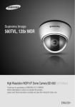
Anywhere in Real-time Network Camera SNC-570 User’s Manual Thank you for purchasing a SAMSUNG Ipolis Network CAMERA. Before attempting to connect or operate this product, please read these instructions carefully and save this manual for future use. ENGLISH Preface A brand that is integrated into Samsung's network products, stands for a convenient world (Polis) made safe (Police) through Samsung's superior network performance(Internet protocol). With products' clear digital images transmitted over the internet, real-time monitoring is possible anywhere with an internet connection. Easy remote control functions and the use of existing networks minimize installation costs. With , experience a world of convenience connected anytime, anywhere. Preface Thanks for purchasing of SNC-570 camera. This is a user instruction manual for high resolution WDR network camera and the product mentioned here designates the high resolution WDR network camera. The user who installs and operates the product shall be aware of this manual and other manuals referenced by this manual before the installation and operation and use properly. This manual and the software and hardware explained here are protected by copyright law. So the copy, reprint and translation to other languages of a part of or all contents of this user manual without permission of SamsungTechwin Co., LTD are not allowed except for the copy for general use within the scope of copyright law. i Contents Contents Preface .............................................................................. i Contents ...........................................................................1 Note to User .....................................................................4 Product Warranty and Limitations ....................................7 Warning Symbols .............................................................8 Danger..............................................................................8 Caution ........................................................................... 11 Ch1. Overview .......................................................................13 1.1. SNC-570 Network Camera Introduction..................14 1.2. Features ..................................................................14 Ch2. Production Description ...............................................19 2.1. Components and Accessories.................................20 2.2. Section names and functions ..................................21 2.2.1. Front ...................................................................... 21 2.2.2. Side........................................................................ 22 2.2.3. Bottom ................................................................... 23 2.2.4. Back....................................................................... 24 2.3. Recommended PC specifications ...........................26 Ch3. Installation and Network Setup...................................27 3.1. Lens Installation.......................................................28 3.2. Connecting to Monitor .............................................32 3.3. Connecting to Power ...............................................33 1 Network Camera SNC-570 3.4. Connection to External Control Connector..............35 3.5. Network configuration and connection method using Web page .39 Ch4. How to Use Web Viewer ..............................................45 4.1. How to Use Web Viewer..........................................46 4.1.1. Login ...................................................................... 46 4.1.2. Web Viewer screen ................................................ 47 4.2. Using Administration page.......................................53 4.2.1. Initialization Screen after Connecting (Basic Screen).... 53 4.2.2. Live ........................................................................ 54 4.2.3. Basic ...................................................................... 55 4.2.4. Network.................................................................. 57 4.2.5. Video Analytics....................................................... 70 4.2.6. Privacy ................................................................... 72 4.2.7. Record (Using the SD Memory) ............................. 74 4.2.8. User ....................................................................... 76 4.2.9. Pan/Tilt/Zoom......................................................... 79 4.2.10. Motion Detection .................................................. 80 4.2.11. Alarm/Sensor........................................................ 82 4.2.12. Time ..................................................................... 85 4.2.13. LOG ..................................................................... 86 4.2.14. Upgrade ............................................................... 87 4.2.15. System Reboot..................................................... 88 Ch5. How to Operate Camera ..............................................89 5.1. Setup MENU ...........................................................90 5.2. How to Set Up Functions.........................................91 5.2.1. LENS ..................................................................... 92 2 Contents 5.2.2. EXPOSURE ........................................................... 94 5.2.3. WHITE BALALACE (WHITE BAL.)......................... 97 5.2.4. BACKLIGHT........................................................... 99 5.2.5. SSNR................................................................... 102 5.2.6. DAY/NIGHT.......................................................... 104 5.2.7. IMAGE ADJ.......................................................... 106 5.2.8. SPECIAL.............................................................. 107 5.2.9. EXIT..................................................................... 114 Ch6. Troubleshooting......................................................... 115 Specifications ...............................................................120 Dimension ....................................................................123 Note If you refer to the enclosed Quick guide and the Manual in the CD, you can learn how to use Network Manager. 3 Network Camera SNC-570 Note to User This machine’s electromagnetic waves have been registered as suitable for business purposes; the retailer and consumer should be aware of this registration. If in the case of wrongful purchases, please exchange the product for a home use product. Correct Disposal of This Product (Waste Electrical & Electronic Equipment) (Applicable in the European Union and other European countries with separate collection systems) This marking shown on the product or its literature, indicates that it should not be disposed with other household wastes at the end of its working life. To prevent possible harm to the environment or human health from uncontrolled waste disposal, please separate this from other types of wastes and recycle it responsibly to promote the sustainable reuse of material resources. Household users should contact either the retailer where they purchased this product, or their local government office, for details of where and how they can take this item for environmentally safe recycling. Business users should contact their supplier and check the terms and conditions of the purchase contract. This product should not be mixed with other commercial wastes for disposal. 4 Note to User Samsung Techwin cares for the environment at all product manufacturing stages to preserve the environment, and is taking a number of steps to provide customers with more environment-friendly products.The Eco mark represents Samsung Techwin s will to create environment-friendly products, and indicates that the product satisfies the EU RoHS Directive. 5 Network Camera SNC-570 Correct disposal of batteries in this product (Applicable in the European Union and other European countries with separate battery return systems.) This marking on the battery, manual or packaging indicates that the batteries in this product should not be disposed of with other household waste at the end of their working life. Where marked, the chemical symbols Hg, Cd or Pb indicate that the battery contains mercury, cadmium or lead above the reference levels in EC Directive 2006/66. If batteries are not properly disposed of, these substances can cause harm to human health or the environment. To protect natural resources and to promote material reuse, please separate batteries from other types of waste and recycle them through your local, free battery return system 6 Product Warranty and Limitations Product Warranty and Limitations The manufacturers of this product do not take any responsibility for this product; therefore, the manufacturer does not authorize the third-party, but allows that retailer is responsible. The product warranty does not extend to cover accidents, negligence, abuse, or wrongful use for the whole or any part of the product. Additionally, the manufacturer does not provide warranty for any additional parts or affiliations. The warranty is for one year from the purchase date. During the period, warranty does not extend to malfunction in these areas. y Malfunction due to user’s negligence y Dismantlement or replacement by the user y Connection to alternate power source y Malfunction due to natural disasters (fire, flood, tsunami, etc.) y Replacement due to wear and tear y Instability of network 7 Network Camera SNC-570 Warning Symbols Before attempting to connect or operate this product, please read these instructions carefully and save this manual for future use. Danger : Misuse or wrongful operation of the product may result in death, injury or bring about other fatal results. It indicates absolute caution when operating. Caution : Misuse or wrongful operation of the product may result in slight injury or damage to the product. It indicates caution when operating. Note : Indication that the user needs to be aware of certain matters, or will find matters helpful in operating the product. Danger Before Setup y Please set up the proper voltage before connecting to power source. y Please be sure the power is turned off before setup. 8 Danger y There is risk of shock or fire; be sure to avoid setup in places with high humidity. y To prevent shocks, please connect the ground wire. y Do not install the camera on a surface that can not support it. y Unless the surface is suitable, it could cause falling or other hazards. During Use y When opening the product cover, there is a risk of electric shock. Only a professional should open the cover. y Please use only in an environment with standard temperature and humidity. y Please do not plug in multiple products to a power source; it is often the cause of fires. y Please do not place water or heavy objects on the product; it is often a cause of malfunction. y Please do not use in a location with propane gas, gasoline or other flammable substances to avoid risk of explosion or fire. y Please do not touch the power plug with wet hands to avoid electric shock. y Do not pull on the power plug with too much force; a damaged plug may cause electric shock or fires. y Don’t connect the RJ-45 cable to a terminal by constraint. y Stop using your camera when you find a malfunction. If you use your camera around smoke or unusual heat for a 9 Network Camera SNC-570 long time, Fire may be caused. y Random replacement of built-in battery by other types of batteries may cause explosion. The battery shall be replaced by the same battery. The used batteries shall be disposed carefully because they can cause environment pollutions. y The battery shall be replaced by the same battery. y The used batteries shall be disposed carefully because they can cause environment pollutions. y The lithium battery incorporated in this product is not user replaceable. Replacement of the lithium battery will be done by a trained technician. y For information on its replacement, please contact your service provider. Disassembly and Cleaning y There is a risk of malfunction, shock or other dangers. Please do not disassemble or attempt to fix the product. y To prevent malfunction or shock, please do not use a wet cloth or oil-based cleaning product to clean the product exterior. Clean the exterior of the product with a dry cloth. 10 Caution Caution y Do not install under extreme temperature conditions Use only under temperature conditions between -10°C and +50°C. Provide good ventilation when using in high temperature conditions. y Do not install under unstable lighting conditions. Severe lighting changes or flickering may hinder normal camera operation. y Do not drop the camera or subject it to physical shock. May cause a product malfunction. y Never keep the camera face to strong light directly. May damage the CCD. y Avoid touching the camera lens. The lens is the most important component of the camera. Be careful not to smear it with fingerprints. y Do not expose the camera to rain or other types of liquids Wipe dry any liquids. Liquids may contain minerals that are corrosive to Electronic components. y Do not expose the camera to radioactivity. Radioactivity exposure may damage the CCD. y Do not disassemble the camera. If you disassemble the product as you please, a Repair Center doesn’t repair it for free. 11 Network Camera SNC-570 y Please check the created network place first, before trying to connect to a network. y Please use only the power adapter that is provided with the product. y Please check national laws to be sure that using the product for monitoring purposes is not illegal. 12 C h 1. O v e r v ie w Network Camera SNC-570 1.1. SNC-570 Network Camera Introduction The SNC-570 is a high-tech network camera that uses MPEG-4 codec technology to allow high compression rates and clear picture quality by allowing for high frame rates to be transmitted through the network. By using the network, remote connection, monitoring, and control is possible from any location for simple use; additionally, set-up requires only a network. The SNC-570 Network Camera utilizes embedded software solutions (Embedded Web Server, Embedded Streaming Server, Network Protocol) developed by SamsungTechwin, and guarantees performance and safety while offering various solutions through Internet integration. 1.2. Features High Resolution The horizontal resolution of 560TV lines at color mode and 700TV lines at BW mode can be achieved by using a high density SONY CCD having double speed 410,000 pixels, which provides clean, noiseless and reliable pictures. Multi-channel Real-time image encoding Single Chip MPEG4 and JPEG codec enables real time image encoding and transmission through multi-channel of classified resolution of D1/CIF/QCIF. 14 1.2. Features Wide Dynamic Range (WDR) The main function of the Wide Dynamic Range (WDR) is to accumulate the scope of contrast between the brightest and darkest points in the picture. WDR employing SV-IV chipset provides prominent back light compensation effect in high-contrast environment. High sensitivity against low illumination Diagonal 6 mm (1/3”) CCD of enhanced sensitivity and DSP chipset catch contour and color of objectives only with starlight illumination in the dark, which provides reliable outdoor surveillance performance. - 0.001Lux (Lux for color mode) - 0.00004Lux (Lux for black and white mode) SSNR (Samsung Super Noise Reduction) Samsung’s high performance DSP chipset SV-IV reduces GAIN variance effectively to deliver clean and clear-cut images. DAY & NIGHT fuction Day & night function and Sens-up function by ICR (IR Cut-Filter Removal) operation produce high quality images for 24 hours. ※ Sens-Up function delays exposing time to improve CCD sensitivity. ※ Day & Night function allows users choose color mode or BW mode depending upon illumination. 15 Network Camera SNC-570 PoE (Power Over Ethernet) PoE function is to supply power through the LAN cable together with data transmission without power cable for user convenience. DIS (Digital Image Stabilizer) DIS (Digital Image Stabilizer) function compensates camera shaking to obtain clear-cut images. SD Memory function SD Memory function is to memorize an event at the SD Memory when it activated. Privacy function Privacy function is to determine surveillance area not to display on the monitor for privacy protection. RTSP, RTP/UDP, RTP/Multicast support Electronic IRIS Electronic IRIS shuttering enables continuous automatic shutter control in the range of 1/60 to1/120,000 seconds. VIDEO/DC Lens driver Simple switch operation is enough to choose video driving lens or DC driving lens. High Sensitivity High sensitivity color CCD delivers vivid images in the low illumination of 0.001 Lux. (Sens-up, 256X) 16 1.2. Features Combination of motion detection and alarm Combination of motion detection, video analytics and alarm enables still image storage in the SD Memory or transmission of still image via email or FTP. High data compression ratio High compression in MPEG-4 provides fast transmission and relatively high volume transmission of frame in the same network band. Real time interactive audio Transmission Additional functions SENS-UP, Mirror, SHARPNESS, SYNC choice (INT/LL) 17 Network Camera SNC-570 18 C h 2. P r o d u c t io n D e s c r ip t io n Network Camera SNC-570 2.1. Components and Accessories High Resolution, Day&Night Network Camera User’s Manual / CD / Quick Guide C-Mount adaptor Auto iris lens connection plug Cross Cable DC 12V Adapter / Power Cord 20 2.2. Section names and functions 2.2. Section names and functions 2.2.1. Front ① Lens cap Lens cap should be placed until the lens mounted. ② C-Mount lens adapter Mount the C-Mount lens on this adapter. ③ CS-Mount lens adaptor Replace the C-Mount lens adapter with this. ④ Back Focus adjustment lever Adjust focal length with this. 21 Network Camera SNC-570 2.2.2. Side ⑤ Auto Iris Connector The camera controls the iris lens via this connector. ⑥ SD MEMORY CARD SLOT Insert the SD memory card here. Caution SNC-570 is designed to accept SD card only, not for MMC. Do not insert the card in reverse, otherwise the slot can be damaged. Only 128MB - 2GB SD cards can be used while 4GB SDHC is supported. We recommend the FAT32 format. 22 2.2. Section names and functions 2.2.3. Bottom ⑦ Tripod Mounting seat Bolt down the tripod here using screws specified as L below. 1/4”-20UNC(20THREAD) L:4.5 ㎜±0.2 ㎜(ISO Standard), or 0.197’’(ASA Standard) ※ Tripod mounting module can be relocated to the top surface. In this case, use the screws shorter than 4 mm, otherwise the camera can be damaged seriously. Caution This camera package does not include the mounting bracket. Please refer to the user's manual for installation of the mounting bracket. 23 Network Camera SNC-570 2.2.4. Back ⑧ Audio Terminal IN : Audio input terminal to connect microphone OUT: Audio output terminal to connect speaker system ⑨ Auto iris lens selector (switch) Select DC drive lens or Video drive lens with this switch. ⑩ Reset button You can reset all zones of the camera to default level pressing this button longer than 5 seconds with LED blinking. Wait one minute after resetting the power before turning on any function of the camera. ⑪ RS-485 RS-485 is the adequate cable to connect to SRX-100B for pan/tilt control. 24 2.2. Section names and functions ⑫ ALARM terminal Alarm signal input terminal (I) is to connect to the external sensing devices such as infrared sensor, thermal sensor, etc. Alarm signal output terminal (O) is to connect to the external warning devices such as alarm light or siren, etc. ⑬ ETHERNET The standard RJ-45 connecter is adequate to connect to 10/100 Mbps Ethernet. Electrical power transfer via PoE (IEEE 802.3af) is available. Orange colored LED blinking is the sign of successful data transmission of the camera in the network. ⑭ RESET LED You can reset all zones of the camera to default level pressing this button longer than 5 seconds with LED blinking. ⑮ POWER LED When you turn on the camera, power LED flashes. ⑯ Power terminal A terminal is to connect power cable. ⑰ Video output terminal This terminal is for the video output and is used to set the focus and other functions when the camera is installed. ⑱ GROUND terminal An earth ground terminal for camera body and peripherals. 25 Network Camera SNC-570 Caution When you connect SNC-570 network camera to the PoE apparatus, the voltage transferred via LAN cable may be abnormally high. Please contact to our distributor for installation or dismantling PoE system. 2.3. Recommended PC specifications Items CPU Main Memory VGA OS Web Browser Resolution Network DirectX 26 Specifications Intel core2 duo E4300 or higher processor 2GB or higher RAM 256M or higher recommended Window 2000, XP, 2003 Internet explorer 5.5 or higher 1024*768 or higher 10/100 Base-T Ethernet 9.0C or higher C h 3. Installation and Network Setup Network Camera SNC-570 3.1. Lens Installation Lenses are sold separately. Lenses such as an auto iris lens, CSMount lens and C-Mount lens can be used. Caution To effectively realize major performance of this product, the use of DC format auto-iris lens is recommended. Any foreign objects and fingermarks on the lens can cause inferior image quality in low light level conditions. Please keep the lens clean. When using an auto iris lens 1. Please peel off about 8mm of the outer skin of the auto iris lens cable. Approx. 8 ㎜ 2. Please peel off about 2mm of the outer skin of the insulated conductor inside the lens cable. Approx. 2 ㎜ 28 3.1. Lens Installation 3. Please remove the cover of the auto iris lens connection plug and solder the lens cable to the connector pin in the plug. Pin No Lens DC No.1 Pin No.2Pin Damping Damping + No.3 Pin Drive + No.4 Pin Drive - VIDEO Red(power) NC White (video signal) Black(GND) 4. Please replace the auto iris lens connection plug cover and take off the CCD protection cap, and then attach the auto iris lens to the camera by screwing it in clockwise. 5. Please insert the connection plug that is connected to the auto iris lens cable into the auto lens connector, which is located on the side of the camera. 6. Please set the lens selection switch, located on the back of the camera, to DC or VIDEO depending on the type of auto iris lens which is being used. 29 Network Camera SNC-570 When using a C-Mount lens Please take off the CCD protection cap and attach the C-Mount lens to the camera by screwing it in clockwise. When using a CS-Mount lens 1. Please attach the CS-Mount lens to the camera by screwing it in clockwise. 2. Please attach the CS-Mount lens to the camera by screwing it in clockwise. 30 3.1. Lens Installation Caution Please use the specified lens connection parts as shown in the picture below. The use of the wrong sized parts of the wrong size may cause damage to the inside of the camera or result in poor fitting. Use of a lens which is too heavy affects the balance of the camera and may cause a malfunction. Please use a lens that weighs less than 450g. Please select Av mode if possible when adjusting the automatic light control (ALC) of an auto lens. Use of PK mode may cause hunting. C-mount lens: 10 ㎜ or less CS- mount lens: 5 ㎜ or less 31 Network Camera SNC-570 3.2. Connecting to Monitor Please connect the video output terminal located on the back of the camera to the monitor. SNC-570 Network Camera Monitor y The connection method varies depending on the type of monitor and accessories. Please refer to the user's manual for each instrument. y Please turn off the power when connecting. y Please select Hi-Z on the 75Ω/Hi-Z switch for the intermediate video TV set and select 75Ωfor the Intermediate device as shown in the picture below. SNC-570 Network Camera 32 Intermediate End monitor 3.3. Connecting to Power Caution This product is the network camera which transmits video through network, video output terminal is for installation and used to determine imaging range when installing the product. Please make sure that the video output terminal of this product is not connected to any recording equipment as this can cause problems. 3.3. Connecting to Power AC/DC Power Both of AC24V and DC12V can be used for the input power of this product. When using other adaptor not the adaptor (DC12V/4A) provided by the company, make sure that the specification is over AC 24V/1A or DC12V/2A. AC/DC Combined use In case of SNC-570, as recommended adaptor specification is over AC 24V/1A or DC12V/2A, please use surely the adaptor complying with this specifications. 33 Network Camera SNC-570 Table 3-1. When the resistance value of copper wire is at [20℃(68℉)] Copper wire size (AWG) #24 (0.22㎟) #22 (0.33㎟) #20 (0.52㎟) #18 (0.83㎟) Resistance value (Ω/m) 0.078 0.050 0.030 0.018 Voltage drop(V/m) 0.028 0.018 0.011 0.06 y As shown in the Table3-1, voltage decreases as the wire gets longer. Therefore use of an excessively long adaptor output line for connection to the camera may affect the performance of the camera. ※ Standard voltage for camera operation: DC 12V±10%, AC 24V±20% ※ There may be some deviation in voltage drop depending on the type of wire and the manufacturer Caution In case PoE and power adaptor are connected to camera simultaneously, the power authorized first by the product is used. PoE(Power Over Ethernet) POE(Power Over Ethernet)is the function of LAN related devices, which supports data and power simultaneously with only connection of LAN cable without separate power input cable installation for power excitation to the product. When connecting camera to PoE device, please connect to the device complying with PoE (IEEE802.3af) specifications. In case non-standard product is used, it may cause performance degradation or trouble. 34 3.4. Connection to External Control Connector 3.4. Connection to External Control Connector The input order of terminal from left is Alarm input/Alarm output/Ground/RS-485 ‘+’signal/ RS-485 ‘-’signal. When connecting cable, push stripped part of electric wire in while pushing quadrangle button and take hands off from the button then the wire will be fixed. ① ② ③ ④ ⑤ Alarm Input Alarm Output Ground RS-485 ‘+’ Signal RS-485 ‘-’ Signal 35 Network Camera SNC-570 Connecting Alarm Input This is the input terminal for external alarm signal, use it by connecting as following. DC+3.3V 카메라 내부 Camera Inside 47KΩ Alarm In CMOS CMOS 입력 Input Sensor 220Ω 0.1 GND y In case of selecting Normal Open at setup menu: In case of contact type, it is short and in case of active type, sensor input acts at “LOW” level. y In case of selecting Normal Close at setup menu: In case of contact type, it is open and in case of active type, sensor input acts at high impedance status(open collector). 36 3.4. Connection to External Control Connector Connecting Alarm output This is the output terminal for external alarm signal, use it by connecting as following. Alarm Out Open Collector CMOS CMOS 출력 Output Relay 2.2KΩ Relay Relay 출력 Output Relay Relay전원 Power 10KΩ GND Alarm output part is Open Collector structure and can be composed by using relay. Rated maximum value is DC +24V, 100 mA. 37 Network Camera SNC-570 Connecting RS-485 ※ Connect the RS-485 to SRX-100B with the plus (+) signal to plus and minus (-) signal to minus. ※ The terminating resistance of the RS-485 can be set in the RS485 termination of the Basic menu. ※ GND pin of RS485 part may be not to be connected. ※ It may be effective when communication is not working properly. Connecting Audio ※ Connect the Phone Jack Audio Input terminal (Mic, Mono) to the AUDIO IN terminal. ※ Connect the Phone Jack Audio Output terminal (speaker) to the AUDIO OUT terminal. 38 3.5. Network configuration and connection method using Web page 3.5. Network configuration and connection method using Web page Use when there is one SNC-570 network camera to be installed. 1. Please connect user’s PC to SNC-570 network camera using cross cable. 39 Network Camera SNC-570 To configure network, the internal IP must be registered in the user’s PC. Note After pressing internet protocol (TCP/IP) properties, press the ‘advanced’ button to go into advanced configurations. Add with 192.168.1.XXX. 40 3.5. Network configuration and connection method using Web page Caution 192.168.1.100 is the IP address for the camera and will be unavailable as an internal IP address. 2. Please launch a Web browser on user’s PC and enter [192.168.1.100] in the URL address field and push <Enter> button. Connect to Webviewer login window of SNC-570 network camera. 3. Please login with administrator’s authorization and move to ‘Network’ page.(Default value for administrator login is ID: admin, PW:11111111) 41 Network Camera SNC-570 Note 4. 42 Default value is ID: admin, PW: 11111111 Please configure according to the network environment where SNC-570 network camera will be installed and push <Save> button to save the configuration. 3.5. Network configuration and connection method using Web page ① LAN / xDSL/ DHCP Configuration Item LAN Use xDSL DHCP Description When network product is connected to normal local LAN or when connected to static IP, the network data to be allotted to the IP is configured. When using xDSL dynamic IP, enter the ID and PW. When automatically receiving IP through DHCP server, the DHCP functions are activated. ‘DHCP’ is used in the LAN environment where the DHCP is activated. Generally, for mid/large scale, DHCP servers are operated through LAN and for small-scales, IP sharers use DHCP functions. 43 Network Camera SNC-570 ② Port Configuration Item Port Setting 참고 44 Description The connection port and http, ftp port configurations can be set here and the DDNS use can be checked. Use DDNS changes its IP address every time the user attempts to connect to the ISP and when the product is connected to a cable modem or xDSL modem. In this case, the user cannot know the changed IP address. When a product that uses dynamic IP is registered on the DDNS server, when wishing to connect to the product, the changed IP address can be easily recognized. Register the product in the DDNS server in order to register the IP address in the DDNS server. Enable the “Use DDNS” option and enter the submitted ID and password into the server. C h 4. How to Use Web Viewer Network Camera SNC-570 4.1. How to Use Web Viewer 4.1.1. Login To connect the login page, enter IP address of the camera on a internet Web browser and push enter key. Enter user ID and password and push <Login> button, then it move to related Web page. (Default value is ID: admin, PW: 11111111 ) If you click <Guest> button, it move to WebViewer page under the Guest authenticated status. In this case, administrator should permit the Guest connection. Note 46 If you logged in first as a administrator mode, please change the password of administrator. It can prevent from other users connection to administration page. 4.1. How to Use Web Viewer 4.1.2. Web Viewer screen Web Viewer screen is composed of menu area for camera/video configuration and screen area for displaying input video from camera. Controls (Activated when Video Analytics is enabled) Video Analytics (Convert to Video Analytics mode) This button is activated when the Video Analytics Enable option is selected on the Video Analytics page. A menu arrangement of the Analytics mode is different with one of the Control mode. 47 Network Camera SNC-570 RESET (Displayed when the Video Analytics mode is on) This sets the current screen image to the background. Alpha branding (Displayed when the Video Analytics mode is on) Makes changed parts appear half-transparent. Caution 48 It is not recommended to use alpha branding in the low specification system. 4.1. How to Use Web Viewer Flip Image Turns the screen upside down. Stretch Image Expands the screen to the size of D1 when selecting CIF and QCIF for resolution. Save Image Saves the channel screen as a JPEG file. Compression Video compression mode (the mode of compressing video) - MPEG, JPEG Resolution Video resolution (the size of video screen transmitted) - NTSC : D1(704x480), Half D1(704x240), CIF(352x240) - PAL : D1(704x576), Half D1(704x288), CIF(352x288) 49 Network Camera SNC-570 Frame Rate - Setting on the Basic page The number of maximum video frame transmitted for each second. - 1, 5, 10, 15, 20, 25, 30 Quality - Setting on the Basic page Video quality - Very High, High, Normal, Low, Very Low Pause Stops video for a while. OSD Displays related information. Displays the title Removes the title 50 4.1. How to Use Web Viewer Camera Setup Displays OSD control button of camera. Camera OSD is displayed Day&Night Day&Night configuration function (Color, B/W configuration) PTZ Control PTZ control function 51 Network Camera SNC-570 Instruction for Camera OSD control button <↑>, <↓> button Moves selection displaying arrows up and down on camera OSD menu. <←>, <→> button Changes configuration of selected field on camera OSD menu. <Set> button Displays camera OSD or moves to upper/lower menu of selected field. <Exit> button Terminates camera OSD. For configuring the function and detail operating method of SNC570 network camera, refer ‘ch5. How to Operate Camera’. 52 4.2. Using Administration page 4.2. Using Administration page 4.2.1. Initialization Screen after Connecting (Basic Screen) When connection is successful, the below screen will be displayed. 53 Network Camera SNC-570 4.2.2. Live Please Move to Web Viewer page [Web Viewer live screen] 54 4.2. Using Administration page 4.2.3. Basic Setup menu for basic configuration. Video/Audio Setup Item Video Format Description If you select the type of camera installed (NTSC or PAL), you can choose the size of the view on the camera. 55 Network Camera SNC-570 Item Description Video compression type (This defines how the video is compressed.) Defines the size of the live screen view. Compression Type Initial Resolution Selects the video quality. You can still view uninterrupted video with the quality reduced if you use a low speed Internet connection. Defines how many frames the camera will transfer per second. Video Quality Video FrameRate Defines what video channel will be used by the camera. Determines whether to use an audio input channel for the camera. Determines whether to use an audio output channel for the camera. Video Channel Audio-In Channel Audio-Out Channel Specifies how many users (up to 20) can connect to the camera via the network. Audio Amplifier You need to set the sensitivity to Low with an amplifier-equipped microphone and to High with an amplifier-free Microphone (set it to low for line-in signals). Max User Count Microphone Sensitivity Product Information Item Model Mac Address Camera Name Location Description Memo 56 Description Describe camera model. Describe MAC address of camera. Name each camera to identify multi cameras on the network. Describe each camera location. Describe more information of camera. Describe contact number of the camera operator. 4.2. Using Administration page 4.2.4. Network Network Configuration menu. 57 Network Camera SNC-570 Network Configuration You can select LAN interface for static IP configuration, xDSL modem and DHCP for cable modem. Item LAN xDSL DHCP Description Configure network assignment information of a camera connected to the local area network or to the static IP of xDSL modem. For dynamic IP of xDSL, enter ID and password of xDSL in the username box and password box. For IP router or cable modem interface, select DHCP. Port/DDNS Configuration Item Connection Port HTTP Port/ FTP Port Use DDNS Description Connection port is to control communication with camera. (Default : 4000) HTTP /FTP port is to access to the camera web page or to use FTP function. (Default : http=80, ftp=21) Determine use of DDNS server. DDNS allows you to connect to the server transforming dynamic IP. Continuous Jpeg Image Transmission Item Enable FrameRate Server Name Home Directory User ID User Password 58 Description Determine use of Continuous JPEG Image Transmission function. Determine frame rate (frame per seconds) to send out. Enter domain name or IP address of the FTP server. Configure home directory to store assigned data of the FTP server. Enter ID to access to the FTP server. Enter Password to access to the FTP server. 4.2. Using Administration page Streaming Engine Item Description RTSP/TCP Enable RTP/UDP Enable RTP/Multicast Enable Streaming Image Resolution Determines whether to use RTSP/TCP. Determines whether to use RTP/UDP. Determines whether to use RTP/Multicast. The default setting of Multicast IP is 224.0.1.1. Determines the resolution of the Streaming Engine. Unicast RTP streaming (RTP over UDP) is the adequate image transmission method to send out the latest image despite of video loss. RTP over RTSP (RTP tunneled over RTSP) is useful to install a relatively simple firewall which accepts RTSP data streaming. Note Unicasting is adequate to VOD (Video On Demand) broadcasting, since it sends out video data only with data transmission demand. Multicast RTP (RTP over UDP) sends out the latest video image to the users anytime despite of video loss. It is more efficient to use broadband transmission to broadcast video image for multi users simultaneously. Since multicast through internet is not available, you need a router to allow multicast. Note Up to 10 connections at the same time may be regarded as one connection. 59 Network Camera SNC-570 DDNS Usage Registration process of DDNS is as following Step1) Complete the registration form in iPOLiS website. The website is ‘www.samsungipolis.com’. Figure 1. Website of iPOLiS 60 4.2. Using Administration page Figure 2. Membership Registration: SIGNUP Figure 3. Membership Registration: Input your information. 61 Network Camera SNC-570 Step2) Register the equipment after login. Figure 4. Login SNC-570 Figure 5. The list of registered equipment. 62 4.2. Using Administration page Figure 6. Product Registration. (Confirm repetition certainly at domain registration.) SNC-570 Figure 7. The list of registered equipment. 63 Network Camera SNC-570 Step3) Configure DDNS information in the equipment. Click the part of Network Configuration in website of Network Camera. Click “USE DDNS” in order to do “Enable” and input the address of DDNS Server. (Default: www.samsungipolis.com ) Enter the ID and Password that is written when register product is in iPOLiS website. The Configuration of DDNS in SNC-570 is Completed. 64 4.2. Using Administration page Step4) Confirm the connection status of relevant product in product list of iPOLiS website. SNC-570 Figure 8. The List of Product. Be able to confirm the information of connected equipment if click <check> button of ‘Product information’. 65 Network Camera SNC-570 user SNC-570 Urban security Namsan Tower 2008-05-22 Figure 9. Product information Move to Login website of relevant product if click <view> button of ‘ view’. The buttons which are <Edit> and <Delete> of ‘product management’ move to relevant page through input password to item that fertilize or erase information of registered equipment in List of product. Only, ‘ID(Domain)’ of product should establishes again as ‘ID(Domain)’ after deleting because it can’t be fertilized. Figure 10. Edit/Delete 66 4.2. Using Administration page How to use Streaming Engine We recommend VLC media player among Streaming Engine products. Step1) Network Page configuration Click the certain function of Streaming Engine and press <Save> button. - To update Network Page configuration, the system will reboot. Step2) VLC media player execution When you execute VLC media player, below screen capture will appear. Step3) VLC media player connection and configuration RTP/UDP connection Select ‘FILE’ in the menu and click ‘Open Network Stream…’. Enter ‘rtsp://[serverip]/mpeg4unicast’ in the RTSP URL and press <OK> button to connect to RTP/UDP. 67 Network Camera SNC-570 RTP/TCP connection Select ‘Settings’ in the menu and click ‘Preferences...’ then check the ‘Advanced options’ box at the bottom of right side of the monitor, below options will appear. 68 4.2. Using Administration page Check the ‘Use RTP over RTSP (TCP)’. Enter ‘rtsp://[serverip]/mpeg4unicast’ in the RTSP URL and press <OK> button to connect to RTP/TCP. RTP Multicast connection Enter ‘rtsp://[serverip]/mpeg4unicast’ in the RTSP URL to connect to multicast. ※ TCP configuration should be cleared again to execute RTP Multicast. 69 Network Camera SNC-570 4.2.5. Video Analytics The Analytics feature compares the current screen against the one at the time of clicking on Set button and marks changed areas. It can detect up to 5 areas. Item Description Video Analytics Enable Determines whether to use Video Analytics. Transition Time Shows the period of time maintaining a changed screen for Detection. (3, 6, 9, 12, or 15 sec) 70 4.2. Using Administration page Item Reset Time Stable Ratio Caution Description This is the time needed to convert the current screen to the standard one. (30 or 60 sec, 10 min, 30 min or ∞) Determines whether to detect an object, depending on the size. (1:Low - 5:High) When Video Analytics is enabled, the motion detection feature is automatically disabled. Depending on your system, the Video Analytics feature may not function properly. 71 Network Camera SNC-570 4.2.6. Privacy For privacy protection, you can specify areas to hide. Item Grid Display Select Area Privacy Enable 72 Description Auto hide mode of screen split tool to select area. In the process of Privacy configuration, press <Select All> button to configure the whole screen or press <Deselect> button to cancel the configured screen area. Determine use of Privacy function. 4.2. Using Administration page Item Blending Level Masking Color Description Blending Level function is to determine masking transparency of excluded area in the range of 1 to 255. Level 255 is perfect transparent. Masking color can be selected among Grey, Blue and Violet.. 73 Network Camera SNC-570 4.2.7. Record (Using the SD Memory) When Motion Detection, Video Analytics or Sensor is detected, you can save them. Then, if an Event is occurred, you can also watch them. Item Description SD Memory Size It shows total storage capacity of SD memory. SD Memory Using Size It shows SD memory occupation. SD Memory Free Size It shows balance capacity of SD memory. Warning Message Off In the event of memory overflow or memory error, it is not display the warning message. Overwrite In the event of memory overflow, it erases record files chronically and records new events. 74 4.2. Using Administration page Item Description Analytics Detection Recording When Analytics is detected, you can save it. Motion Detection Recording Sensor Detection Recording When a motion is detected, you can save it (MD). When the Sensor detects a motion, you can save it. Plays the video. Stops the video. Pauses the video. Save the video image as a JPEG file. Event Record List Caution Event record list stored in the SD memory. ※ This system records images 5 seconds before and after the event. ※ You can record Event up to one minute. We provide SD Memory card only, not the MMC. Only 128MB - 2GB SD cards can be used while 4GB SDHC is supported. We recommend the FAT32 format. Make sure that you turn off the camera before you insert or take out the SD memory card. 75 Network Camera SNC-570 4.2.8. User This describes password change for administrator or user registration. Item Description Administrator Password Change Change password of administrator Guest Setup User clicks ‘Guest’ button to decide whether allowing guest to connect Main Viewer. Current User You can register new user or delete, and set up user’s authority. The default password is user1 - user5. 76 4.2. Using Administration page ※ Set up user authority User’s authorities set up at ‘Current User’ are as follows. Catetory Video Control Description Use video related setup function (Compression, Resolution, Video Analytics) Pan, Tilt, Zoom, Audio output, Alarm output Audio Audio Input USE Whether relevant account is used (If not checked, not allowed log-in) Example 1) In case control function is limited (Do not check Controls box) ※ Pan, tilt, zoom, audio output, alarm output function icon is inactivated 77 Network Camera SNC-570 Example 2) In case video function is limited (Do not check Video) ※ Compression, Resolution set up icon is inactivated. 78 4.2. Using Administration page 4.2.9. Pan/Tilt/Zoom Configures PTZ Swing and Preset of the camera. Item PTZ Display OSD Display Device ID Model Caution Description Display PTZ menu. Display OSD. Select an identification number of the camera. Select the model installed. When PTZ is enabled, the Video Analytics feature may not function properly. 79 Network Camera SNC-570 4.2.10. Motion Detection This sets up motion detection function of camera. Item Grid Display Select Area MD Enable 80 Description Basic grid, used to choose area on the screen, is displayed or hidden. When selecting motion detection area, click <Select All> button to select all areas, or click <Deselect> button to cancel the selected area. Decide whether you use motion detection function. 4.2. Using Administration page Item Description MD Sensitivity Setting up sensitivity to detect motion to adjust input video by situation. You can select 1-5, and 5 is the highest. Caution When the motion detection feature is enabled, the Video Analytics feature is automatically disabled. 81 Network Camera SNC-570 4.2.11. Alarm/Sensor This sets up necessary information when using alarm function by attaching sensor to camera. 82 4.2. Using Administration page Alarm/Sensor Setup ◊ Digital In Setup Item Description Sensor No. Shows the sensor number (Sensor1). Sensor Type Types of sensors are ‘Normal open’ and ‘Normal close.’ This selects up type of connected sensor. ◊ Digital Out Setup Item Description Alarm Set up Digital Out responding when event is recognized by connected sensor (Sensor 1), Video Analytics or Motion Detection (MD) Duration Set up time to operate relay. It means the period from the time when sensor detects event to the time when relay is released. (1, 2, 3, 4, 5, 30 sec and 1, 2, 3 min, or always) FTP In case event occurs by sensor (Sensor 1) or Motion Detection (MD) or Video Analytics on the screen, decide whether transferring related information to FTP. E-mail In case event occurs by sensor (Sensor 1) or Motion Detection (MD) or Video Analytics on the screen, decide whether transferring related information by e-mail. FTP/E-mail Setup Set up FTP server and e-mail information to which related information is transferred in case alarm occurs. Item Server Name FTP Home Directory User ID User Password Description Enter domain or IP address of FTP server. Set up home directory to save relevant data at FTP server. Enter ID to connect FTP server. Enter PW to connect FTP server. 83 Network Camera SNC-570 Item Description Recipient E-mail Address 1 Recipient E-mail Address 2 SMTP Server Name E-mail Use Authentication ID Password Mail Subject Mail Body Note 84 You can designate up to two e-mail address receiving data when alarm occurs. If you use an external E-mail server, enter the name of the E-mail server. If you use an external E-mail server, determine whether to use ID and password. Enter ID to connect the outside e-mail server. Enter PW to connect the outside email server. Enter the subject of mail to be transferred. Enter the body of mail to be transferred. When an event is occurred, a copy of JPEG-format image is transferred to the E-mail or FTP server. 4.2. Using Administration page 4.2.12. Time Current Time Item Date Time Description Current setup date displayed Current setup time displayed Time Setup Item Set Manually Time Server Description Adjust time manually. Set up address of time server for Server 1 - 5. 85 Network Camera SNC-570 4.2.13. LOG Recent activities made for camera are displayed as log. Item Lines View Clear Send Log to Administrator E-mail per Day 86 Description Set up number of lines of the list. Log is viewed with number of lines you set up most recently. Delete logs. Sends logs to the administrator via E-mail at the same time (04:00) every day. 4.2. Using Administration page 4.2.14. Upgrade Upgrade program of SNC-570 network camera. System Upgrade Configuration. Item SNC-570 Firmware Description Upgrades the firmware of the SNC-570 network camera. Factory Mode Setup If you click <Reset> button, server is returned to initial value when shipped from the factory after confirmation procedure by administrator. Caution If you perform the Factory Mode Reset function, the IP will be reset to 192.168.1.100, a value set at the time of shipment from the factory. In this case, you may not log in depending on the installation environment. When you reset a camera function related to video, you need to initialize the setting of the OSD menu as well (see How to Operate Camera in Chapter 5). 87 Network Camera SNC-570 4.2.15. System Reboot Server is rebooted after confirmation procedure of administrator. Click <OK> button to reboot server. 88 C h 5. H o w t o O p erat e C am era Network Camera SNC-570 5.1. Setup MENU Setup Menu LENS EXPOSURE WHITE BALANCE BACKLIGHT SSNR DAY/NIGHT IMAGE ADJUSTMENT SPECIAL EXIT 90 DC SHUTTER RETURN ATW AWC→SET OUTDOOR OFF WDR ON COLOR FREEZE D-ZOOM CAMTITLE PRIVACY LANGUAGE VIDEO AGC MANUAL SENS-UP MANUAL INDOOR BLC HLC OFF B/W V-REV SHARPNESS SYNC DIS RESET AUTO H-REV RETURN MOTION DET RETURN 5.2. How to Set Up Functions 5.2. How to Set Up Functions Use OSD button displayed on Web Viewer screen to set up functions. y 1. : OSD button is popped up in Web Viewer. Please press the <SET> button. y Main setup menu is displayed on the monitor screen. MAIN SETUP Select the function using the UP or DOWN button. ► 1. LENS 2. EXPOSURE 3. WHITE BAL 4. BACKLIGHT 5. SSNR 6. DAY/NIGHT 7. IMAGE ADJ 8. SPECIAL 9. EXIT DC ATW OFF ON AUTO Change the status using the LEFT or RIGHT button.. 91 Network Camera SNC-570 2. Select a desired function using the Up and Down buttons. y Place the cursor over a desired item. 3. Set up a selected item by using the Left and Right buttons. 4. To finish the setting, select ‘EXIT’ and press the SET button. 5. Press the OSD button to quit OSD. Caution An item with the icon also has sub menus. To select a sub menu, select an item with the icon and press the SET button. An item with the - - - icon is unavailable due to function settings. 5.2.1. LENS Using this function, you can control screen brightness. 1. Select the lens of the DC or Video by adjusting the relevant switch on the back of the product. 2. When the SETUP menu screen is displayed, select LENS by using the Up and Down buttons so that the arrow indicates LENS . 3. Select the connected lens type by using the Left and Right buttons. (DC ↔ MANUAL, VIDEO ↔ MANUAL) 92 5.2. How to Set Up Functions MAIN SETUP ► 1. LENS 2. EXPOSURE 3. WHITE BAL 4. BACKLIGHT 5. SSNR 6. DAY/NIGHT 7. IMAGE ADJ 8. SPECIAL 9. EXIT DC ATW OFF ON AUTO DC/VIDEO: Auto iris lens selection When DC is selected, you can control screen brightness. The range of brightness control is between 1 and 70. Adjust the brightness appropriately for optimal screen brightness. Caution Some lenses may not work properly, depending on the setting of the BRIGHTNESS LEVEL. When Using a Video-Type Auto Iris Lens Adjust the ALC adjustment terminal on the lens appropriately. In general, set it to AV (Average). It may not work properly depending on the installed lens. Set the Level VR of the lens to 93 Network Camera SNC-570 the optimal value. Set AGC to OFF and adjust the Lens VR to an appropriate brightness. Adjust the Lens VR, adjust the BRIGHTNESS, and then check if the screen brightness changes properly. Otherwise, adjust the Lens VR again. MANUAL : Select Manual lens 5.2.2. EXPOSURE MAIN SETUP 1. LENS ► 2. EXPOSURE 3. WHITE BAL 4. BACKLIGHT 5. SSNR 6. DAY/NIGHT 7. IMAGE ADJ 8. SPECIAL 9. EXIT DC ATW OFF ON AUTO 1. When the SETUP menu screen is displayed, select EXPOSURE by using the Up and Down buttons so that the arrow indicates EXPOSURE. 2. Select a desired mode using the Up and Down buttons. 94 5.2. How to Set Up Functions SHUTTER : You can select either auto or manual shutter. - A.FLK : Select this when you experience picture flicker, which can happen when there is a clash with the frequency of the installed lighting. - ESC : Select this to control the shutter speed automatically. If ESC is selected, the shutter speed is automatically controlled depending on the ambient illumination of the subject. - MANUAL : You can control shutter speed manually. Caution To produce better results with A.FLK, do not use it in conjunction with the WDR mode of the BACKLIGHT menu. When the SHUTTER is set to ESC after selecting the Internal Synchronization Type, the picture may become unstable if the camera faces a bright fluorescent light. Therefore, take care when choosing the installation position. ESC and MANUAL modes are only available together when the lens is set to MANUAL. When the SHUTTER is set to MANUAL or A.FLK mode, SENS-UP will be disabled. AGC (AUTO GAIN CONTROL): The higher the gain level, the brighter the screen - but the higher the noise. - OFF : Deactivates the AGC function. 95 Network Camera SNC-570 - LOW : Allows automatic gain control from 0 to 30dB. - HIGH : Allows automatic gain control from 0 to 42dB. SENS-UP: When it is night or dark, the camera automatically detects the light level and maintains a clear picture if this mode is activated. - OFF : Deactivates the SENS-UP function. - AUTO : Activates the SENS-UP function. RETURN: Select this to save the changes in the EXPOSURE menu and return to the SETUP menu. Caution If you press the SET button in ‘AUTO’ mode, You can adjust brightness by increasing or decreasing the shutter speed. (X2~X256) Note that the higher the zoom level, the brighter the screen, but the more likely it is that an after-image will appear. Although Noise, Spots, and Whitish symptoms may occur in SENS-UP operation when the zoom level is increased, this is normal. 96 5.2. How to Set Up Functions 5.2.3. WHITE BALALACE (WHITE BAL.) Use the White Balance function to adjust the screen color. 1. When the SETUP menu screen is displayed, select ‘White Bal.’ by using the Up and Down buttons so that the arrow indicates ‘White Bal.’. 2. Select a desired mode using the Up and Down buttons. MAIN SETUP 1. LENS 2. EXPOSURE ► 3. WHITE BAL 4. BACKLIGHT 5. SSNR 6. DAY/NIGHT 7. IMAGE ADJ 8. SPECIAL 9. EXIT DC ATW OFF ON AUTO ※ Select one of the following 5 modes, as appropriate for your purpose. ATW : Select this when the color temperature is between 1800°K and 10500°K. INDOOR : Select this when the color temperature is between 4500°K and 8500°K. OUTDOOR : Select this when the color temperature is between 1800°K and 10500°K. (sodium light inclusion) AWC → SET : To find the optimal setting for the current luminance environment in this mode, set the point the camera towards a sheet of white paper and press the SET button. If the environment changes, readjust it. MANUAL : Select this to fine-tune White Balance manually. Set White Balance first by using the ATW or AWC mode. After that switch to MANUAL mode, fine-tune the White Balance and then press the SET button. 97 Network Camera SNC-570 Caution White Balance may not work properly under the following conditions. In this case select the AWC mode. When the color temperature of environment surrounding the subject is out of the control range (e.g. clear sky, or sunset) When the ambient illumination of the subject is dim. If the camera is directed towards a fluorescent light or is installed in a place where illumination changes dramatically, the White Balance operation may become unstable. 98 5.2. How to Set Up Functions 5.2.4. BACKLIGHT This camera is designed so that it delivers a distinctive subject and background at the same time, even when the subject is in backlight, unlike conventional cameras, by adopting a proprietary SV-IV DSP chip. 1. When the SETUP menu screen is displayed, select ‘BACKLIGHT’ by using the Up and Down buttons so that the arrow indicates BACKLIGHT. MAIN SETUP 1. LENS 2. EXPOSURE 3. WHITE BAL ► 4. BACKLIGHT 5. SSNR 6. DAY/NIGHT 7. IMAGE ADJ 8. SPECIAL 9. EXIT 2. DC ATW OFF ON AUTO Select a desired mode using the Left and Right buttons depending on the camera purpose. BLC Enables a user to directly select a desired area from a picture, and to view the area more clearly. - Select ‘BLC’ to adjust the area to be enhanced and enhancement level. WDR: When there are both bright and dark areas at the same time, this mode makes both areas distinctive. 99 Network Camera SNC-570 WDR OFF - Select WDR to adjust the WDR LIMIT and LEVEL. LIMIT: Adjust the WDR Sensitivity by selecting LOW, MIDDLE, or HIGH. LEVEL: Adjust the WDR Brightness by controlling the bar from 0 to 100. HLC (High Light Compensation) : If there is a high light installed in a limited environment such as an apartment parking garage or gas station entrance, removing the high light makes it possible to view car license plates efficiently. - DAY : In normal daylight conditions, the HLC is not activated. - NIGHT : If a high light that is larger than a certain size is present on the screen, remove the high light to see license plates clearly. 100 5.2. How to Set Up Functions - HLC : Enable a user to select a mask color of high light area from a picture. OFF : Not being used. 3. Select a desired mode using the Left and Right buttons and press the SET button. Caution You cannot use the WDR mode when MANUAL or A.FLK mode in ‘SHUTTER’ menu is selected. Since the following symptoms may occur according to the ambient illumination when WDR is selected, set it to OFF. - Color or screen changes unnaturally. - Noise appears in the bright part of the screen. Since the performance of the WDR function may be affected by the area of the bright part of the screen, optimize the installation angle 101 Network Camera SNC-570 for the best WDR performance. If you increase LIMIT, the screen display may be distorted. For high performance of WDR function, using DC Iris lens rather than manual lens is recommended. Because there can be a difference in the effectiveness of HLC according to the amount of light area in the screen, optimize the installation angle for the best HLC performance. In a dark environment, the HLC is only activated when a high light that is larger than a certain area is present. The HLC is not activated in light or overly dark conditions. 5.2.5. SSNR This function reduces the background noise in a low luminance environment. 1. 102 When the SETUP menu screen is displayed, select ’SSNR’ by using the Up and Down buttons so that the arrow indicates ’SSNR’. 5.2. How to Set Up Functions MAIN SETUP 1. LENS 2. EXPOSURE 3. WHITE BAL 4. BACKLIGHT ► 5. SSNR 6. DAY/NIGHT 7. IMAGE ADJ 8. SPECIAL 9. EXIT 2. DC ATW OFF ON AUTO Select a desired mode using the Left and Right buttons. OFF: Deactivates SSNR. Noise is not reduced. ON: Activates SSNR so that noise is reduced. 3. Set the SSNR mode to ‘ON’ and press the SET button. Then you can adjust the noise reduction level. Caution You cannot set the SSNR to ‘ON’ or ‘OFF’ when the AGC mode of the EXPOSURE menu is ‘OFF’. When adjusting the noise reduction level of the SSNR mode, remember that the higher the level set, the more the noise level will be reduced but that after image may also occur. 103 Network Camera SNC-570 5.2.6. DAY/NIGHT You can display pictures in color or black and white. 1. When the SETUP menu screen is displayed, select ‘DAY/NIGHT’ by using the Up and Down buttons so that the arrow indicates DAY/NIGHT. MAIN SETUP 1. LENS 2. EXPOSURE 3. WHITE BAL 4. BACKLIGHT 5. SSNR ► 6. DAY/NIGHT 7. IMAGE ADJ 8. SPECIAL 9. EXIT 2. DC ATW OFF ON AUTO Select a desired mode using the Left and Right buttons according to the picture display you want. COLOR: The picture is always displayed in color. B/W: The picture is always displayed in black and white. Please press SETUP button to turn on or off the burst signal on B/W mode. AUTO : The mode is switched to Color in a normal environment, but switches to B/W mode when ambient illumination is low. To set up the sswitching time or speed for AUTO mode, press the SET button. 104 5.2. How to Set Up Functions - DWELL TIME : You can select the duration time about changing the day/night mode. (5s, 7s, 10s, 20s, 30s, 40s, 60s) - DURATION : You can select brightness of illumination about changing the day/night mode. Fast Color → B/W B/W → Color 2.5 lux 4lux Slow 0.8lux 6lux ※ The brightness of illumination is changeable by installed environment. You can easily switch between night and day modes by adjusting the D&N button on the webpage. (AUTO ↔ BW, COLOR ↔ BW) Caution When using a Video Auto Iris Lens, if you set the lens level to low, automatic switching between Color and Black & White may not occur. You cannot control the DAY/NIGHT menu when AGC in the EXPOSURE menu is ‘OFF’. At this time, the exchange between DAY mode and NIGHT mode operates as like selecting ‘COLOR’ mode. The camera may focus less well under infrared illumination than under normal illumination. Since the camera may not focus as well under infrared illumination at night as it does under normal illumination, install an Extra-low Dispersion Lens to obtain sharp pictures. 105 Network Camera SNC-570 5.2.7. IMAGE ADJ. 1. When the SETUP menu screen is displayed, select ‘IMAGE ADJ.’ by using the Up and Down buttons so that the arrow indicates IMAGE ADJ. MAIN SETUP 1. LENS 2. EXPOSURE 3. WHITE BAL 4. BACKLIGHT 5. SSNR 6. DAY/NIGHT ► 7. IMAGE ADJ 8. SPECIAL 9. EXIT 2. DC ATW OFF ON AUTO Select a desired mode using the Up and Down buttons. IMAGE SETUP ► 1. FREEZE 2. V-REV 3. H-REV 4. D-ZOOM 5. SHARPNESS 6. RETURN OFF OFF OFF OFF ON FREEZE : You can view still or moving pictures. V-REV: You can flip the image vertically. H-REV: You can flip the image horizontally. D-ZOOM: You can digitally zoom by a factor of X1 to X10. SHARPNESS: As you increase this value, the picture outline becomes stronger and clearer. Adjust this value appropriately depending on the sharpness of the picture. 106 5.2. How to Set Up Functions RETURN : Select this to save the settings for the IMAGE ADJ. menu and to return to the SETUP menu. Caution When H-REV or V-REV is selected, any text in the picture also will be flipped horizontally or vertically. If you increase the SHARPNESS level too high, the picture may become distorted or noise may appear. 5.2.8. SPECIAL 1. When the SETUP menu screen is displayed, select ‘SPECIAL’ by using the Up and Down buttons so that the arrow indicates ‘SPECIAL’. 107 Network Camera SNC-570 MAIN SETUP 1. LENS 2. EXPOSURE 3. WHITE BAL 4. BACKLIGHT 5. SSNR 6. DAY/NIGHT 7. IMAGE ADJ ► 8. SPECIAL 9. EXIT 2. DC ATW OFF ON AUTO Select a desired mode using the Up and Down buttons. SPECIAL ► 1. CAM TITLE 2. SYNC 3. MOTION DET 4. PRIVACY 5. DIS 6. LANGUAGE 7. PRESET 8. RETURN OFF INT OFF OFF OFF ENGLISH CAM TITLE If you enter a title, the title will appear on the monitor. 1) If the SPECIAL menu screen is displayed, use the Up and Down buttons so that the arrow indicates ‘CAM TITLE’. 2) Set it to ‘ON’ by using the Left and Right buttons. 108 5.2. How to Set Up Functions Caution When the CAM TITLE menu is ‘OFF’, no title will be displayed on the monitor screen even if you enter one. SPECIAL ► 1. CAM TITLE 2. SYNC 3. MOTION DET 4. PRIVACY 5. DIS 6. LANGUAGE 7. PRESET 8. RETURN OFF INT OFF OFF OFF ENGLISH 3) Press the <SET> button. 4) Use the 4 direction buttons to move to a desired letter and select the letter by pressing the SET button. Repeat this to enter multiple letters. You can enter up to 15 letters. 109 Network Camera SNC-570 Caution If you move the cursor to CLR and press the <SET> button, all the letters are deleted. To edit a letter, change the cursor to the bottom left arrow and press the <SET> button. Move the cursor over the letter to be edited, move the cursor to the letter to be inserted and then press the <SET> button. 5) Enter a title, move the cursor to ’POS’ and press the <SET> button. The entered title appears on the screen. Select the position to display the title on the screen by using the 4 direction buttons and press the <SET> button. When the position is determined, select ’END’ and press the <SET> button to return to the SPECIAL menu. SYNC In areas where the supply is at 60Hz, you can synchronize the output phase of multiple cameras using the power synchronization function (Line-Lock) without using a synchronization signal generator. INT : Internal Synchronization Type L/L : Power Synchronization Type, Line-lock 110 5.2. How to Set Up Functions - Press the <SET> button. - You can select a desired phase from 0 to 359 when select 'phase'. - You can decide the synchronization between luminance and color signal when select the 'mode'. Caution When using AC power at 60Hz frequency, you can use the L/L type synchronization. When the power is DC 12V, the SYNC. menu is fixed to the ‘INT’ mode. MOTION DET If you connect an alarm device to this camera, you can monitor activity more efficiently, because a signal is generated by the camera whenever motion is detected. The motion detection signal is output through the MD OUT port. 1) When the SPECIAL menu screen is displayed, press the Up and Down buttons so that the arrow indicates MOTION DET . 2) Set up the mode using the 4 direction buttons. - SENSITIVITY : You can select up to 8 MD areas. When SENSITIVITY number is high, motion detection sensitivity is increased to recognize even small movement. - AREA MODE : Determines whether to use the MD area selected in SENSITIVITY. - SEL POS : Determines which of the 4 vertices of each MD area is to be used. 111 Network Camera SNC-570 - YPOS : Determines the coordinate of the vertical axis for SEL POS. - XPOS : Determines the coordinate of the horizontal axis for SEL POS. - FILL→SET : Fills in a selected MD area. Fills in a selected MD area. The color of filling is sequentially selected as brown, orange, blue, cyan, yellowish green, yellow and red. - RETURN : Select this to save the MOTION DET menu settings and return to the SPECIAL menu. Caution MD areas show only MOTION DET menu. Therefore, MD areas don’t display on the monitor screen. PRIVACY Hide an area you want to hide on the screen. 1) When the SPECIAL menu screen is displayed, press the Up and Down buttons so that the arrow indicates ‘PRIVACY’. 2) Set up the mode using the 4 direction buttons. - AREA SEL : You can select up to 8 MD areas. - - AREA MODE: Determines whether to use the area selected in the AREA SEL, and the size and position of the area. 112 5.2. How to Set Up Functions - AREA SEL : You can select up to 8 MD areas. - AREA MODE: Determines whether to use the area selected in the AREA SEL, and the size and position of the area. - MASK COLOR : Determine area color. You can select Gray, Green, Red, Blue, Black, White. - TRANSP : Determine the transparency of selected area as controlling number from 0 to 3. - RETURN : Select this to save the PRIVACY menu settings and return to the SPECIAL menu. DIS (Digital Image Stabilizer) : This function mitigates any picture movement due to external factors such as wind. Caution The chance of resolution decrease is existed because DIS function uses the digital zoom. DIS doesn’t operate illumination is too low. when background DIS doesn’t operate when object pattern is monotonic as like sky or white wall. When using the DIS mode, the D-ZOOM level is required to set up over 46. LANGUAGE: You can select the menu language according to your requirements. RESET: Resets the camera settings to the factory defaults. RETURN: Select this to save the SPECIAL menu settings and return to the SPECIAL menu. 113 Network Camera SNC-570 5.2.9. EXIT Press the SET button in the EXIT menu to save the current settings and exit the SET menu. 114 C h 6. Troubleshooting Network Camera SNC-570 If there are problems in operation, please refer to the items below. If the problem persists, please contact the agent you purchased this product from. Problem Nothing appears on the screen. Solution Please check the power connection. Please check the video signal line connection. Please check and make sure that the auto lens switch is set to DC (VIDEO) when using a DC(VIDEO) lens. Open MS-DOS window to check whether SNC-570 network camera is connected to network. ※ In case of ping 192.168.1.100, replace it with IP address set up at server The video image is not clear. Please check if the lens is clean. Please clean the lens with a clean cloth or brush. Please adjust the contrast feature of the monitor. Please make sure that the screen is not exposed directly to a bright light. Please move the camera if necessary. Please readjust the back focus of the camera. The screen is dark. Please adjust the contrast feature of the monitor. If you have an intermediate device, set the 75Ω/Hi-z properly, and check the terminals. Please check if an auto iris lens is being used and adjust the brightness level. 116 Troubleshooting Problem Solution There is a problem with the camera operation. The camera surface is too hot and black stripes appear on the screen. Please check if an appropriate power source to the camera complies with the manufacturer's standard requirement, or if the voltage keeps changing. The MOTION DETECTION function is not working. Please check if 'MOTION DETECTION' mode is turned on. Please check if the MD LEVEL is too low. Please check the setting of the MD AREA. Colors are not quite right. The screen is flickering. Please check the 'WHITE BAL' setting. (Please refer to page 97) Please check if the camera is facing directly into sunlight or fluorescent light. Please check if an auto iris lens is being used. Please check the connection of the lens connector cable. L/L mode isn't able to be selected. Have you connected your camera to DC power source? Connect it to AC power source. Please check the frequency of power supply (60Hz for NTSC, 50Hz for PAL). DAYNIGHT(Auto) mode is not working. Please check if the AGC menu is set to the OFF position. 117 Network Camera SNC-570 Problem SENS-UP function is not working. Solution Please check if the AGC menu is set to the OFF position. Please check if the SHUTTER menu is set to MANUAL mode. Please check the limit of SENS-UP AUTO mode. Audio is not working Please check the audio is selected from admin page. Please check speaker volume from the viewer. In case input sound through microphone at Viewer is not outputted through Audio Out of server, please check whether Audio Out channel is selected at admin page. Or check whether microphone is available at Viewer. Please check audio driver is working in user’s PC. Video is stopped Please check whether network cable of SNC-570 network camera is correctly connected In case user uses hub or IP router, check whether these network equipments are working properly. Open MS-DOS window and check whether SNC-570 network camera is connected to network. 118 Troubleshooting Problem Solution No image from web viewer Click ‘refresh (shortcut; F5) ’ button at browser to recall the page Check whether power of camera and network cable is properly connected. Check whether computer is connected to network. If you use hub or router, check whether such equipments are properly operated. (Note: Open MS-DOS window and enter network ID of camera at ping 192.168.1.100,) Connect to Admin page to check whether video output is selected. Image transferred to FTP or by E-mail cannot be viewed Video may not be viewed since Divx codec is not installed in user’s PC. Divx codec can decode video compressed with MPEG4. Download and install the latest Divx codec, and check video. http://www.divx.com/divx/download Saved contents is not displayed in the SD memory Make sure that you do not take out the memory card while contents are being saved. Check if the SD memory card is properly inserted. Check if the capacity on the card is correct on the Record Page. Product information is not displayed on the local network Check if the network cables are properly connected. Check the status after pressing the RESET switch on the back of the product for five seconds to initialize it. 119 Network Camera SNC-570 Specifications Model Name SNC-570N SNC-570P VIDEO Imaging Device 1/3" Vertical double density interline CCD Total Pixels 811(H) x 508(V) 795(H) x 596(V) Effective Pixels 768(H) x 494(V) 752(H) x 582(V) Scanning System 2:1 Interlace Frequency H:15.734 KHz/ V:59.94 Hz Horizontal Resolution Color : 560 TV Lines (Min.), B/W: 700 TV Lines (Min.) Min. Illumination Color : 0.3 Lux (50 IRE @ F1.2), 0.001 Lux ( Sens-up, 256X ) B/W : 0.01Lux (50 IRE @ F1.2), 0.00004Lux (Sens-up) S/N (Y signal) 52 dB H: 15.625 KHz/ V : 50.00 Hz OSD Built-In (Multi-language support) Camera Title On/Off Day & Night Auto (ICR) / Color / BW Backlight Compensation WDR / BLC / HLC / Off Dynamic Range 52dB Motion Detection On/Off (Output via communication) DIS On/Off Privacy Masking On / Off (8 Programmable zones) SSNR On / Off (Level adjustable) Sens-up Auto / Off (Selectable limit ~ X256) Gain Control High / Low / Off White Balance ATW / AWC / Manual / Indoor/ Outdoor Electronic shutter speed Auto (NTSC : 1/60~1/120,000sec, PAL : 1/50~1/120,000sec) / Manual / A.FLK IRIS DC / Video 120 Specifications Performance Encoding Resolution 704x480(D1), 352x240(CIF), 176x120(QCIF) 704x576(D1), 352x288(CIF), 176x144(QCIF) Compression MPEG-4/JPEG Dual CODEC with transcoder Encode Rate Up to 30fps @ 704x480 Transmission speed Up to 100Mbps Up to 25fps @ 704x576 Remote users 20 simultaneously Maximum Protocol support RTP/UDP, RTP/Multicast, RTSP, TCP/IP, DHCP, DNS, DDNS, HTTP, SMTP, FTP, PPPoE and NTP Network Video Analytics Missing object detection(Appear/Disappear) Security Password Protection 5 User Level Output 1 BNC (560 TVL, For installation) Input 1 Phone Jack, Line in (1Vpp) / MIC in (2K ohm) Interface Monitor Audio Alarm Connections Storage Output 1 Phone Jack, Line out (1Vpp) Compression ADPCM Sampling rate 8 KHz Inputs Terminal 1 input, NO/NC Outputs Terminal 1 output, NO/NC Remote notification Via E-mail or oneshot FTP, continuous FTP transmission Ethernet RJ-45 10/100 Base-T PTZ control interface RS-485 SD(SDHC) Memory Stored event image, Back-up 128MB,256MB,512MB,1GB,2GB SD memory card, 4GB SDHC memory card 121 Network Camera SNC-570 S/W Install program Provided IP installer Provided Dedicated viewer Provided (SNM64) ActiveX server controller for Web Provided General Input Voltage Dual (12V DC/ 24V AC), PoE (IEEE 802.3af) Power Consumption Max. 8.5W Operating Temperature/Humidity -10°C ~ +50°C / 30% ~ 80%RH Dimension(W×H×D) 74x61x152mm(2.91"x2.4"x5.98") Weight 580g(1.28 lb) Lens Mount C/CS 122 Dimension Dimension 123 SAMSUNG TECHWIN SALES NETWORK SAMSUNG TECHWIN CO., LTD. 145-3, Sangdaewon-dong, Jungwon-gu, Seongnam-si, Gyeonggi-do 462-120, Korea Tel: +82-31-740-8151~8 Fax: +82-31-740-8145 SAMSUNG OPTO-ELECTRONICS UK, LTD. Samsung House, 1000 Hillswood Drive, Hillswood Business Park Chertsey, Surrey KT16 OPS Tel: +44-1932-45-5308 Fax: +44-1932-45-5325 SAMSUNG TECHWIN AMERICA,LTD. 1480 Charles Willard St. Carson, CA 90746, UNITED STATES Tel: +1-310-632-1234 Fax: +1-310-632-2195 www.samsungtechwin.com www.samsungcctv.com www.samsungipolis.com P/NO : Z6806.0913.01B