1
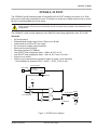
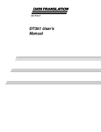
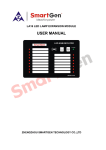
OP5360-2 USER MANUAL
5 to 30V
32 Digital Output Module
www.opal-rt.com
Published by
OPAL-RT Technologies, Inc. 1751 Richardson, suite 2525 Montreal, Quebec Canada H3K 1G6
www.opal-rt.com
© 2014 OPAL-RT Technologies, Inc. All rights reserved
Printed in Canada


CONTENTS
OP5360-2, 32 DOUT................................................................................................................................. 5
features. .............................................................................................................................................................5
.................................................................................................................................................5
APPLICATIONS..................................................................................................................................................6
recommendations
SPECIFICATIONS................................................................................................................................. 7
OP5360-2 Datasheet OPAL-RT Technologies 3
OP5360-2, 32 DOUT

OP5360-2, 32 DOUT
The OP5360-2 type B module provides 32 isolated Push-Pull DOUT divided in two banks of 16. Each
bank can be separately powered by the user. The board can accept up to 30Vdc and can sink or source
50 mA dc (recommended) with no trip action.
!
Higher currents will trip the current protection and all the output levels provided in this datasheet will not
be applicable
The OP5360-2 is ideal for high-frequency (up to 500 KHz) and voltage applications from 15V to 30V.
features
•
•
•
•
•
•
•
•
•
•
32 Dout push-pull
Wide operating voltage range: Vuser 5 Vdc to max 30 Vdc
Load current up to 50 mA DC per output
OV and reverse voltage supply protection
Short-circuit current limitation
Operating frequency DC-500Khz
Low ON/OFF time propagation delay: ≤ 200ns @ 25°C at 5 V
Low ON/OFF time propagation delay: ≤ 65ns @ 25°C from 15 to 30 V
Outputs are tri-stated.
Outputs may be connected in parallel for higher (2 times) current capability
-- Use matched pair (example: DOUT_0 with 1 , DOUT_2 with 3, etc.)
User supply
Supply protections
Over Voltage
Reverse Voltage
FAULT
GND-ISO
V CC
ENA
IN
SC Protection DOUT
From Simulator
GND-ISO
GND-ISO
Figure 1: OP5360-2 bloc diagram
OP5360-2 Datasheet OPAL-RT Technologies 5
OP5360-2, 32 DOUT
DB37F Pin Assignments
recommendations
Users should adjust the power supply level (through the DB37 connector) to get the proper high voltage
level at the DOUT.
Use a proper damping circuit, (a serial resistor capacitor circuit tied to the GND as close as possible to
the user Device Under Test) to minimize ringing and over/undershoot according to the connection length
(from OP5360-2 to user DUT).
The following parameters are a good starting point for the RC values: R=150Ω , C = 100pF. Tuning is
necessary, according to application parameters.
APPLICATIONS
•
•
•
•
Efficient power MOSFET and IGBT Sswitching
Switch-mode power supplies
DC-to-DC converters
Motor control, solar power
DB37F PIN ASSIGNMENTS
Connector P1 Ch. 0-15
OP5360-1 pin
OP5360-1 pin
DB37F
DB37F
DB37F
assignment
assignment
Connector P2 Ch. 16-31
OP5360-1 pin
OP5360-1 pin
DB37F
assignment
assignment
1
+DOUT00
20
-DOUT00
1
+DOUT16
20
-DOUT16
2
3
4
5
6
7
7
9
10
11
12
13
14
15
16
17
18
19
+DOUT01
+DOUT02
+DOUT03
+DOUT04
+DOUT05
+DOUT06
+DOUT07
+DOUT08
+DOUT09
+DOUT10
+DOUT11
+DOUT12
+DOUT13
+DOUT14
+DOUT15
21
22
23
24
25
26
27
28
29
30
31
32
33
34
35
36
37
-DOUT01
-DOUT02
-DOUT03
-DOUT04
-DOUT05
-DOUT06
-DOUT07
-DOUT08
-DOUT09
-DOUT10
-DOUT11
-DOUT12
-DOUT13
-DOUT14
-DOUT15
2
3
4
5
6
7
8
9
10
11
12
13
14
15
16
17
18
19
+DOUT17
+DOUT18
+DOUT19
+DOUT20
+DOUT21
+DOUT22
+DOUT23
+DOUT24
+DOUT25
+DOUT26
+DOUT27
+DOUT28
+DOUT29
+DOUT30
+DOUT31
21
22
23
24
25
26
27
28
29
30
31
32
33
34
35
36
37
-DOUT17
-DOUT18
-DOUT19
-DOUT20
-DOUT21
-DOUT22
-DOUT23
-DOUT24
-DOUT25
-DOUT26
-DOUT27
-DOUT28
-DOUT29
-DOUT30
-DOUT31
6
Vuser 1
Vrtn 1
Vuser 2
OPAL-RT Technologies
1
20
-00
-01
-02
-03
-04
-05
-06
-07
-08
-09
-10
-11
-12
-13
-14
-15
00+
01+
02+
03+
04+
05+
06+
07+
08+
09+
10+
11+
12+
13+
14+
15+
Vrtn
Vuser
19
37
Vrtn 2
OP5360-2 Datasheet
OP5360-2, 32 DOUT
specifications
SPECIFICATIONS
Product name
OP5360-2 (32 digital outputs - push-pull)
Part number
126-0466
Number of channels
32 digital outputs
2 banks of 16, fully isolated and independant of each other
Isolation
Galvanic isolator
Output Protection
50 mA resettable fuse
Protection thresholds
Over voltage: 30.1V
Reverse voltage: maximum 30 V.
Output Voltage range
5 to 30 Vdc max
Output configuration
Push-pull, tri-state output
Delay Low-to-High
≤ 65ns @ 25°C for 30 V
≤ 200ns @ 25°C for 5 V
Delay High-to-Low
≤ 65ns @ 25°C for 30 V
≤ 200ns @ 25°C for 5 V
Rise/Fall times
<= 15 ns
Form factor
Mezzanine Type B
Dimensions
6.60 cm x 12.50 cm (2.6” x 4.92”)
I/O connector
80-pin high speed header to carrier
Operating temperature
10 to 40 ºC (50 to 104ºF)
Storage temperature
-55 to 85ºC (-67 to 185ºF)
Relative humidity
10 to 90%, non condensing
Maximum altitude
2,000 m (6562 ft.)
OP5360-2 Datasheet OPAL-RT Technologies 7
CONTACT
OPAL-RT Corporate Headquarters
1751 Richardson, Suite 2525
Montréal, Québec, Canada
H3K 1G6
Tel.: 514-935-2323
Toll free: 1-877-935-2323
Note:
While every effort has been made to ensure
accuracy in this publication, no responsibility
can be accepted for errors or omissions. Data
may change, as well as legislation, and you are
strongly advised to obtain copies of the most
recently issued regulations, standards, and
guidelines.
This publication is not intended to form the
basis of a contract.
Technical Services
www.opal-rt.com/support
UG 14-42287-1-RVN_4.0
12/2014
© OPAL-RT Technologies Inc.