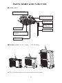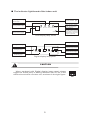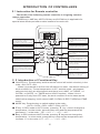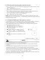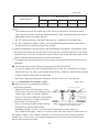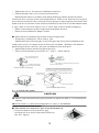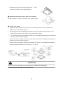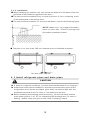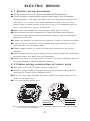
1
Thank you for choosing our company products!
Air conditioning facilities are valuable products. In order to protect
your legitimate rights and interests, please make sure that the
installations are done by professional technicians. This manual is a
general-purpose version for the conditioning systems manufactured
by our CO., the one that you have chosen might be a little different in
appearance from the ones described in the manual . But these differences
will not have any impacts upon your operation and use of the system.
Please read the manual carefully before you operate the system and
check to see if the model is identical to the one you have purchased, keep
the manual properly in case you might refer to it in the future.
CONTENTS
PAGE
NOTICES TO USERS
1
PARTS NAME AND FUNCTION
4
INTRODUCTION OF CONTROLLERS
6
PREPARATIONS FOR INSTALLATION
9
INSTALLATION OF THE UNIT
12
TEST OPERATION
24
MAINTENANCE AND UPKEEP
26
TROUBLESHOOTING
29
ELECTRIC WIRING
31
NOTICES TO USERS
1.1 Safety Notices
"Important Safety Information"affords very important points about how to
operate the unit safely.To prevent injury to the user or other people and property
damage, the following instructions must be followed. Incorrect operation due to
ignoring of instructions may cause harm or damage.
The safety precautions listed here are divided into two categories. In either
case, important safety information is listed which must be read carefully.
!
WARNING
Failure to observe a warning may result in serious injury, grave
accidents even death.
!
CAUTION
Failure to observe a caution may lead to injury or damage to the
equipment.
Please read the mark of the unit carefully .If you detect any abnormality, such
as abnormal noise, smell, fog, temperature rise, creepage, fire and so on;
Please turn off the power supply immediately and call your dealer or local
service
center for instructions. Do not repair the unit by yourself. If necessary,
call the local fire department or Emergency department for help.
!
WARNING
1. Never install the unit by yourself and call the professionals from distributor
or maintenance center for installation, or it may lead to accidents and affect
the performance of usage .
2. Never dismantle the units without the guidance of the professionals, or it may
cause danger .
3. Do not place insecticides or paints and other flammable sprays near the unit
or spray them directly at the unit. It might cause fire hazards.
4. Do not install the main power supply switch at the places where the children
might touch it to avoid of accidents .
5. Do not spray water or other liquid to the air conditioner, or else it may cause
electric shock.
6. Do not touch the unit with wet hands, otherwise it might cause electric shocks .
7. Disconnect the power during lighting storm day, otherwise it might cause
1
Lightning shocks or damage the unit .
8. If the unit will be idle for a long time, disconnect the power to avoid of accidents .
9. The unit shall be equipped with special power supply switch and power line
to avoid of sharing the same power line with other devices. Besides, it adopts
the stated- cross-section wire to supple the power, matching with the
corresponding breaker(with creepage protect function) .
10. The unit is connected with the stated-cross-section earth wire, which is
grounded safely and is not allowed to be connected with the gas pipe, water
pipe, lightning conductor or the telephone earth wire in order to avoid of
electric shocks.
11. Never stop the operation of the unit by pulling out the power supply line in
order to avoid of electric shocks or fire hazards .
!
CAUTION
1. Do not put your hands or sticks into the air vents . As the fan running with high
speed will hurt you.
2. Keep the electric control system from damp to avoid of circuit-short or damage
of unit .
3. After cleaning the filter screen, install the air filter screen quickly .It is not
allowed to operate the unit without the air filter screen which may get the poor
performances.
4. When there are old men, children and patient in the room, please adjust the
room temperature properly.
5. If the unit is interrupted by the lightning or other electromagnetic radiation, cut
off the power, restart the unit after eliminating that factors.
6. Do not clog the air inlet and outlet of the unit.
7. Never use the fuse with incorrect capacity or iron or copper wires for fuse .
8. Keep the unit off the places where might happen fire hazards .Pull out the
power plug immediately and put down the fire with fire extinguisher result from
circuit-short.
9. Cut off the power supply before servicing.
10.Do not touch the pipe on the exhaust side, because the temperature may be
above than 100℃, so it may result in scald.
11. Do not touch the fin and sharp edge which will hurt you.
12. Do not move the unit randomly without professional guidance, otherwise it may
cause the damage of the unit .
2
13.Do not touch the rotary air vents with your hands or other objects to avoid of
accidents or damage.
14. It is forbidden placing goods above the machine set, so as not to result in the
danger of the fall off when they are running.
1.2 Use notices
1. The unit must be installed in outdoor field where there is sunlitproof and
rainproof establishments , or else our company is not responsible for the
problems caused because of wrong installation.
2. All the operation parameters of the unit set , the set values of the protective
device have been set before the delivery , the consumers are not allowed to
change the set values at random , and also are not allowed to make the line of
the protective devices of the machine set , short-circuit or the unit may be
damaged as result of improper protection.
3. When the unit is running, the unprofessional personnel do not touch any
electrical element and buttons, or it will result in serious accident.
4. If the unit goes wrong , don't repair it by yourself , please consult the service
center of the company ( the consultation telephone number can refer to the
back over ). If the machine set is repaired by unprofessional personnel , it may
result in the machine breakdown or the casualty of personnel.
5. During cleaning the unit, never clean the operational panel with benzene,
diluent agent , or chemical cloth and so on , or it will result into fade or the fault
function of the buttons ; It is not allowed to directly sprinkle the unit with
water or cleaning agent, when it is necessary, please clean them with a cloth
that is stained with water or neutral cleaning agent.
6. In order to prolong the service time of the air- condition, please do not start the
compressor frequently. (It should not be more than five times in an hour).
7. The refrigerant used in the machine set is noncombustible and innoxious , as
for the specific gravity of which is greater than air , so when it leaks, it will
diffuse on the ground. As a consequence, if the unit is installed in a room, it
must make sure that the ventilation condition is good , or it way result in serious
asphyxia when the refrigerant leaks.
8. If the refrigerant leaks, stop the unit as soon as possible, and get in touch with
the maintenance and repairmen in time, the flame on the field is forbidden,
because if the refrigerant contacts with the flame, it will decompose into
harmful gas
9. Please service the machine set termly according to the requirements of the
specification , in order to make sure that the operation condition of the machine
set is good.
3
PARTS NAME AND FUNCTION
■ Indoor unit
Short pipe air supply outlet
1. Only to use in s pecial required occasions
2. Only to connect short pipe on one side
Drainage devices (built in type)
Water discharged and removed from
indoor during the refrigeration operation.
Wind guide bar ( it is
located in the air supply
inlet)
Refrigeration agent pipe
Connect the ground
conductor
Ground conductor
Air supply inlet
Drainage pipe
Air filter (it is located in the return
air grillages)
Return air grillages
■ Outdoor unit ( A. Air outlet
B. Air inlet )
A
B
B
A
A
A
NOTE: The drawings above only can be taken as illumination.
4
B
■ The indicator light board of the indoor unit
Defrosting-Preheating
indicator light
Timer indicator light
Running indicator light
RUN
DEFROST TIMER PROTECTION
When the unit breaks
down, the protection
light will be on.
Emergency key
Receiving window of the
remote control signal
EMERGENCY
When the remote controller
is out of order, you can press
down this key to carry out the
emergency operation.
LED Display lamp Panel
Digital display
Running indicator light
When unit failure,
protection light flashes
Emergency key
Run
Defrost
Receiving window of
remote control signa l
Timer Warning
Defrost
Preheating light
Timer setting indicator
Digital display lamp panel
!
CAUTION
When equipped with Digital display lamp panel, please
toggle the fourth point of dialing switches SW1 to DP in the
electronic controller of indoor unit, as shown in the right figure:
5
INTRODUCTION OF CONTROLLERS
2.1 Instruction for Remote controller
The model of the following remote controller is Lingtong common
remote controller.
TURBO key, LAMP key, AIR FLOW key and CLEAN key is applicable for
special latest developed new models instead of normal ones.
AUTO
COOL
DRY
HEAT
FAN
MODE key
It is used for selecting different modes,
such as automatic, cooling,
dehumidifying, heating and ventilating.
SLEEP
LAMP
TURBO
CLEAN
HOLD
F
C
ON
OFF
MODE
TEMP
Set TEMP key
Press▼▲ will decrease or increase
the set temperature and the rang is :
16℃~32℃
ON/ OFF
SWING key
It is used for selecting swing and
stopping switching circularly.
ON/OFF key
It is used for starting or stopping AC.
FAN SPEED key
It is used for selecting wind speeds (
natural wind, high wind, middle wind
and low wind)
TIMER key
It is used for setting timing ON/OFF
and regards hour as its union.
FAN SPEED
SWI NG
AI R FL OW
TI MER
HOLD
SLE EP
TURBO
LAMP
CLEA N
AIR FLOW key It is used for selecting
swing , stable wind, natural wind and
circulating wind.
SLEEP key
It is used for selecting sleep mode
and canceling sleep mode.
HOLD key
It is used for selecting hold mode and
canceling hold mode.
TURBO key
T h e k e y d o e s n’ t i n d i c a t e w i n d
speed and setting sleep mode or
changing modes will cancel TURBO
operation.
CLEAN key
It is used for selecting purification or
canceling purification.
LAMP key: It is used for selecting
lamp being on or being off.
2.2 Introduction of Functional Key
■ ON/OFF key: Press the key and the remote control will switch circularly in the
order : ON→OFF→ON.
When it is powered on at first from off state to on state, the default setting of
work condition is ( The set temperature is 25℃ and the mode , wind speed,
swing and air door are all automatic and there is no LAMP, no TURBO, no
CLEAN, no SLEEP, no TIMER and no HOLD function ). When it is not
powered on firstly from OFF state, the work condition is as the same as the
state before stopping. It will cancel LAMP, CLEAN, SLEEP, TURBO and TIME
mode.
■ MODE key: Press the key to switch modes in the order :
AUTO→COOL→DRY→HEAT→FAN→AUTO
■ ▼ key: In DRY mode or AUTO mode, pressing ▼ key cannot change the
temperature. In other mode, press the key once and the temperature will
decrease 1℃ in the order : 32℃→31℃→…→17℃→16℃ .
■ ▼key:In DRY mode and AUTO mode, pressing ▼ key cannot change the
temperature. In other mode, press the key once and the temperature will
increase 1℃ in the order: 16℃→17℃→…→31℃→32℃ .
6
■ FAN SPEED key: The default wind speed is in the automatic wind mode when
starting firstly. The remote control won’t react by pressing the key because
the wind speed can’t be adjusted and in low speed in dehumidifying mode. In
other mode, press the key to switch modes in the order : automatic wind→ high
speed →middle speed→ low speed →automatic wind.
■ SWING key : In dehumidifying mode, the swing mode is in the stable wind
mode without change. In other mode, press the key to switch modes in the
order: swing →stable wind→natural wind →swing.
■ AIR FLOW key : The default air flow is in the swing mode when starting firstly
and press the key to switch modes in the order: SWING →STOP →SWING.
■ TIMER key : The default mode is in no timing state, press the key to set timing
time . The switch order is: 1H→2H→ … →24H→cancel→1H… . Press the key
to set timing starting in the OFF state and set timing stopping in the ON state.
After setting timing function, the time keeps decreasing per hour until the
time decreasing to the timing on or timing off and the timing display will be
cancelled at the same time . Pressing MODE key can’t cancel timing in
timing mode which will set out timing time by pressing other key.
■ HOLD key: The default state is in no HOLD key state, press the key to select
modes in order: HOLD key →cancel HOLD key→ HOLD key ; In HOLD key
mode, all keys except HOLD key of the remote control can’t work .
( NOTE: In HOLD key mode, the remote and operation panel of the unit both
will be locked automatically by pressing the key and press the key again , they
will be unlocked. As for the split unit , it only hold the control other than
EMERGENCY key and the panel will make a reaction.)
■ SLEEP key : Press the key to switch modes in the order: SLEEP→ cancel
SLEEP→ SLEEP. The sleeping function won’t be cancelled for changing
modes. Press the key to set sleep mode and the wind speed will automatically
be switched to low speed and it can adjust the wind speed by pressing the
FAN SPEED key (except dehumidifying mode).
■ TURBO key: The default state for the control is no turbo and the key don’t
work in the AUTOMATIC mode, DRY mode and FAN mode ( It will not display
any contents and not send out any codes). The control, however, will switch
between on and off by pressing the key in other mode. The wind speed isn’t
indicated in turbo mode and it will be cancelled for changing modes and
setting sleep mode.
■ LAMP key : The default state is in no LAMP key state, press the key to select
modes in order : LAMP key →cancel LAMP key→ LAMP key; In LAMP key
mode, pressing MODE key can’t cancel the show of LAMP key.
■ CLEAN key : The default state is in no purification state, press the key to select
modes in order : CLEAN →cancel CLEAN→ CLEAN; In CLEAN mode,
pressing CLEAN key can’t cancel CLEAN function. Press the key when
the remote control is closed, the control will switch modes in the order :
CLEAN →cancel CLEAN→ CLEAN; When you stop the unit and turn on the
purification switch, except the wind, the stable swing and air door swing speed
aren’t adjusted.
7
2.3 Notices for operating the remote control
① Don’t place the control near high heat source such as Electric blanket, warm
furnace and so on.
② Don’t expose the control in sun.
③ Take care for it and prevent it from damage for falling down.
④ Don’t place any rolling obstacle between the signal acceptor of AC and the
control, otherwise it may affect sending or incepting signals.
⑤ Don’t spray water or other liquid on the control.
⑥ Don’t place any clog on the control.
NOTE: When the remote control is out of work, please replace the battery and
operated it once ; If the failure hasn’t be cancelled, please take urgent operation
methods to restart the AC.
2.4 Replace batteries of the remote control
If the following condition appears, which mean that the batteries have been
used up, please take out of the old batteries and change for new ones.
① After sending the signal, the air conditioner can not send receiving sound.
② The display screen is not clear
The operating steps are as follows:
■ Remove the back cover, take out of
the old batteries.
■ Replace batteries, please notice the
poles “+” and “-” on the batteries.
■ Close the back cover and set the current
time.
■ Make sure whether it indicates a.m. 0:00
or not.
Pay attention to poles of “+”and “-”
!
NOTE
1. New and old batteries can not be used together.
2. If the remote controller will not be idle for long time, please take out of the
batteries.
3. The service life of the dry batteries, accorded with the requirements of the
standard of JIS or IEC, is 6 to 12 months under common condition ;
Overrunning the service time or using dry batteries , which are not accorded
with the above mentioned specifications, the liquid seeping phenomenon may
be occur on the battery and the remote control won’t work.
4. There is “Advised Service Time” marked on the battery, the practical service
time may be shorter than the advised one.
8
PREPARATIONS FOR INSTALLATION
!
CAUTION
The installation of the unit has to be carried out by the professional
installation operator. Improper installation of the unit may cause water
leakage, an electric shock or fires .
3 . 1 Selection of the installation site
3. 1. 1 Installation sites for the indoor unit
① Please install the indoor unit in the spacious places where the air
blown out by the indoor unit can reach every corner of the room as quickly as
possible and also can provide the space to maintain the indoor unit .
② Make sure that the air inlet and the outlet of the indoor unit should not be
blocked, nor be affected by the adjacent heat and the hydrosphere.
③ It should be installed in a clean place where there is little oil gas and little of
steam.
④ It should not be installed in a place where there is the inflammable gas .
⑤ It should be never installed at the place beside the equipments with high
frequency, such as the high frequency electric welding machine.
⑥ It should never be installed in these places where the fire alarm is near.
⑦ It should never be installed in these places where there are full of acid solvent .
3.1.2 Installation sites for the outdoor unit
① If possible, do not install the unit where it is exposed to direct sunlight or
install a sunshade facility;
② Make sure your neighborhood will not feel uncomfortable with the noise or the
exhaust.
③ Make sure that it is easy to install the connecting pipes or cables ;
④ It should not be installed in a place where there is the inflammable gas.
⑤ During the heating mode, the water drained off the outdoor unit, make sure
the drain water from chassis should be well drained away by the drain hole to
an appropriate place, so as not to interfere other people.
3.2 Requirements of the installation and the maintenance space
(Applicable for outdoor units)
3.2.1 Installation of one single unit
① As for the case that there are barriers on the top of the
equipment , make sure there is enough installation
space shown in the figure below no matter whether
there are barriers in the back of the equipments.
② When the front side (the air outlet)is open, make
sure there is enough installation space shown
in the figure below no matter whether there are
barriers in other three sides around the
equipments. ( the top of the equipment was open)
More than 300
More than 500
More than 300
More than 300
9
More than 300
Less than 1500
⑥ The barriers exist in the four sides of the equipments,
More than 1500
More than 3000
⑤ As for the case that the barriers only exist in the front
and the back side of the equipment. In order to keep
unblocked the air supply inlet and the air outlet of the
outdoor units installed the place where the barriers
exist and without good ventilation,please make sure
that the height and the width of the barrier should be
in the following ranges ( As long as the front and the
back sides space of the equipments both can satisfy
the basic conditions, the space of left side or right
side is free. )
■The width of the barriers is less than 1.5 times of the
width of the indoor units.
■The height of the barriers is less than 1 time of the height
of the indoor units.
Less than 300
④ As for the case that barriers exist in the front
and the back sides of the equipment , the
installation shown in the following figure is not
allowable.
More than 1500
③ As for the case that the barriers only exist in
front of the equipment , please keep open in
the back , left and right sides and the top side
of the equipment.
⑦ As shown in the following figure, you must
the equipments can not be installed even though the
make sure enough space for the maintenance
top of the equipment is open.
operation of the equipments in front of the
More than 300
More than 500
equipment.
Maintenance space
More than 500
More than 300
3.2.2 Installation of several units(unit: mm)
■ Installation in parallel . (please dismantle the bolts besides the matching pipeline)
More than 500
More than 300
Less than ten units
10
More than 1500
■ Arrange in multi-row
■ Arrange in face-to-face blowing ways
More than 500
More than 5000
More than 5000
3.2.2 The case for installation of the equipments on the roof or other strong wind
places
If the outdoor unit is installed on the roof or other spacious places , you should keep
air outlets of outdoor units from the strong wind, which may lead to the lack of air
flow to cool or heat the heat exchanger and get a poor heating or cooling
performance even result in breakdown.
① If the unit is installed in the place near the wall,
keep its air outlet pointing the wall and make sure
that the unit will be 500mm away from the wall.
② When the air outlet was affected by the strong
Wind direction
wind or the direction of the wind, remove the
unit so as to keep the wind will be blown at
the air outlet in the vertical direction.
11
Wind direction
INSTALLATION OF THE UNIT
4. 1 Install Indoor unit
4.1.1 Installation place
When the temperature of the ceiling inside is higher than 30℃, and RH is
higher than 80%, More than 10mm heat insulation materials,such as fiber
glass cotton or froth polyethylene should be slicked on the casing of the unit.
(if the thickness of the heat insulation materials is more than 10mm, the extra part
should be folded up and placed in the opening of the ceiling).
■ The indoor unit can be installed on the ceiling with the height of 2.5~2.5mm.
■ When installing the indoor unit, the lifting screw rod will be used and make sure
installation foundation is firm enough to support the unit, otherwise,please
take some measurings to reinforce it prior to installation. The hole pitch
has been marked on in the installation paper matrix, please refer to those
specification and find out the places where the reinforcing measures should be
taken.
■ Make sure there is no obstacles in the place where is 1meter away from
the air outlet.
Installation space
unit: mm
More than
1500
Air outlet Air inlet Air outlet
More
than1500
More than1000
The distance between
the equipments and
the ground is more than 2500
H
More than1500
Installation dimension
More than1500
unit: mm
Dimensions(H)
Model (kBtu/h)
For 18,24 series
230
For 36,48,60 series
285
4.1.2 Installation procedures for indoor units
■ The position relationship between the opening in the ceiling, the unit and the lifting screw
( 150)
C(the indoor units)
E(the distance between the lifting
screw machine)
B(the opening in the ceiling)
A(the decoration panel)
The base of
the hanger
Refrigerant agent
A direction
Ceiling
The lifting screw(x4)
More than 20
D(the distance between the
lifting screw)
C(the indoor units)
B(the opening in the ceiling)
A(the decoration panel)
12
unit: mm
Dimensions(H)
Model (kBtu/h)
For 18,24,36,48,60 series
A
B
C
D
E
950
890*
840
680
780
NOTE:
① The dimensions of the opening of the ceiling marked by the star symbol
can surpass 910mm, but the overlap sections of the ceiling and the decoration
panel should be more than 20 mm.
② As for existing ceiling, a proper opening for installation should be dig
a. On the installation paper-matrix, you can get the detailed information about
the dimensions of the opening of the ceiling.
b. Before installation, please finish the installation of all ducts ( refrigerant duct,
drainage duct)and the connection of the all power lines(the power lines of the
outdoor unit), once the installation has finished, the ducts and the power lines
can be connected with the indoor units immediately.
c. The opening in the ceiling can reinforce the ceiling and prevent the ceiling from
vibrating.
■ The installation of the lifting screw(using the W3/8 M10 bolt)
① In order to support the unit, the ground anchor bolts are needed for existing
ceiling and as for new built house and ceiling, however,buried anchor bolts
or other parts(supplied in the field site) .
② And then adjust the distance between anchor bolts and the ceiling.
50~100
unit: mm
4.1.3 Installation for indoor units
■ When there is no installation position
in the ceiling board
The installation example
Roof
① Attach the base of the hanger on the
lifting screw, the nuts and washers are
Anchor bolt
used in two ends of hanger base to
The long nut or
screw scribea
firmly fix the base.Besides,the washer
The lifting screw
positioning board is used to prevent
Ceiling
the washer from falling off.
NOTE: all the parts above mentioned will be
② As for the dimensions of the opening
supplied at the installation site
of the ceiling, please refer to the
installation paper-matrix or consult the constructor or the carpenter.
The installation paper-matrix is fixed on the unit with three screws and on
the paper-matrix, the central position of the opening in the ceiling has been
marked out . The corner of the water drainage groovy at the water outlet of the
duct is also fixed by screws.
13
③ Adjust the unit to the correct installation position.
④ Check whether the unit is in the horizontal level.
Because the indoor unit has inside water drainage switch and float switch.
Check the four corners of the units separately to make sure that the four corners
are in the horizontal level by using the level gauge or the polythene duct filled with
water (if the unit inclines to the reverse direction to the flow of condensation water,
it may lead to the float switch out of work and result in water dropping).
⑤ Remove the washer positioning board and fasten the nut .
⑥ Remove the installation paper-matrix.
■ When there is installation position in the ceiling board
① Temporary installation ofthe indoor unit
Attach the base of the hanger on the lifting screw, the nuts and washers are
used in two ends of hanger base to firmly fix the base. Besides,the washer
positioning board is used to prevent the washer from falling off.
② Adjust the position and the height of the unit
③ Carry on the operation procedure of ④ and ⑤ steps above;
Nut (it is supplied at site)
Washer (accessories)
Insert
The washer positioning board (accessories)
The base of the hanger
[Firmly fix the washers]
Screw up (Double nut preload)
[Firmly fix the base of the hanger]
The b olts o n o ne a ngle o f t he e xport o f t he d uct
ar e fi xe d at the angl e par t of the dra inag e chann el
The center of the
ceiling opening
Install the paper - matrix
Screw (accessories)
Level gauge
Polyethylene duct
[Fix and install the papier-mache]
4.1.4 Install the panel
!
CAUTION
● Never keep the panel facing the ground nor again the wall or on protuberant
objects.
● Never crash or strike the swing plate in case of breakdown.
■ Take down the return air grill from decoration panel:
① Press the button of the return air grill,
and then lift one end of the button (Refer to
the left figure)
Button
14
② Draw the grill up to an angle of about 45°, and
remove it ( Refer to the right figure)
■ Remove the seal cover at the four corners
(Draw the seal cover out , Refer to the right figure)
■ Install the panel
① Align the swing motor on the panel to the tubing joints of the body properly.
( Refer to the following figure)
② Hang the draw hooks opposite to swing motor of the decoration panel on the
hooks of the indoor unit. (Refer to the following figure)
③⑥ Then hang the other two panel hooks onto corresponding hangers of the body.
( Refer to the following figure)
④ Screw the four hexagonal screws under the draw hook into approximately 5mm.
(the panel will raise along with it)
⑤ Screw up the screws so that the thickness of the air-proof materials between
the panel and the indoor unit reduces to 5 ~ 8mm.
①
Draw hook
②
The position
of nosepiece
Packing material
Indoor units
②
The ceiling
materials
5 millimeters
to 8 millimeters
Air vent
The decoration
panel
The swing baffle
electrical motor
③
④
!
CAUTION
Do not coil the wiring of the swing motor into the seal sponge.
15
Draw hook
If the screwing is too loose,it
will cause following faults.
Therefore, screw up the screw
again to the stated requirement.
After finishing twisting the screw,
if there is still slit between the ceiling
and the decoration panel, please
readjust the height of indoor unit.
When indoor unit is located in
the horizontal position but the
drain water can not be drained
out, please adjust the height
of the indoor unit through the
angle hole on the decoration panel.
Air leaks
Air leakage
in the ceiling
Contamination
The water drop condenses,
The water drop falls
No slit
■ Lifting height of the indoor unit
Please adjust the lifting height of the indoor
unit as the right figure:
Indoor
10~13
① If there is slit between indoor unit and panel,
it will be harmful as the following:
a. Condensation will be generated outside
(ceiling inside) and inside the product
because of the air in the ceiling or the gas
Cool air leak
leakage from the ceiling.
b. The horizontal leaf blade will condensate, the
water will splash and condensation will be
generated in the machine because of air current
blowing out disorderly.
② The circuitry of the decoration panel(please
see the right figure)
a. The connector of the wire of the swing electrical
motor should be properly attached (located on
⑥
Indoor
decoration panel)
unit
b. If unconnected, then the swing plate will not act
c. Insure that the wire of the swing electrical motor
is not trapped between indoor unit and the
decoration panel.
Panel
Indoor
The air guide
clearance
Panel
Panel
The schematic diagram of the circuit
(Different from real condition)
4.1.5 Install return air grill and close cover
■ Install the return air grill
Following the opposite installing steps with " 4.1.4 Install the panel”to carry
on the installment. Rotating the return air grill, it may be installed in 4directions.
If needing to adjust the installment direction of the return air grill, or users put
forward new requirement, installment direction can be changed.
16
!
CAUTION
Do not coil the wiring of the swing motor into the return air grill when
installing.
■ Fix the close cover on the panel (refer to the following figure)
Insert the four pins on the
close cover into the corresponding
hole on the decoration panel
before installation .
■ Put the return air grill on the panel and then connect the swing motor on
panel and lead connectors of control box to the corresponding joints of
the main body;
■ Install return air grill according to the opposite steps for removing the grill.
■ Reinstall the installation cover plate
■ Fix the rope of the installation cover plate with screws on the bolts of the
installation cover plate (please refer to the lower right figure)
■ Push gently the installation cover plate into the panel.
① Fistly, loose the
top nut
No split
② Adjust the
lower bolt
Install Selftapping screw
of the cover
plate rope
S lide t h e f o u r
slide fastens
into the
corresponding
grooves d u r i n g
installing the
cover
4. 2 Install Outdoor unit
4.2.1 Installation precaution
■ It is advisable to transfer the parts of the unit with complete packing to the
installation field site.
■ Pay attention to the lifting of the unit ,for its center of gravity not at the
central position.
■ Keep the outdoor unit not incline too much,the angle not more than 45°
during transportation(it is not allowed to store the unit in level in the storehouse )
17
4.2.2 Installation
■ When installing the outdoor unit, you should use bolts to fix the base of the unit
(the bolts of the base are supplied on the spot )
■ The unit should be installed firmly in order to prevent it from collapsing result
in the earthquake or the strong wind .
■ The unit should be installed on the concrete basis, refer to the following figure.
NOTE: Make sure the length of the basis
bolts no more than 25 mm(Counting from
More than 25mm
the bottom installation basis)
■ The pitch is no less than 300 mm between the unit installed in parallel .
No less than 300 mm
4.3 Install refrigerant pipes and drain pipes
!
CAUTION
● If there is no special conditions, you should chose the tubes of our company .
● If there are some special conditions, and need purchase other types of the
refrigeration duct , please purchase good heat-insulated pipes with the
thickness more than 9 mm in case of the dewing on the duct.
● Before installing the drainage tube(accessory), you should also purchase
some cable groove(Φ16,ID) for connecting the drainage duct.In case of
dewing, please wrap the groove with 9mm insulating sleeve.
18
4.3.1 Dimensions of refrigerant pipes
Model(kBtu/h)
Refrigerant liquid duct
Refrigerant gas duct
For 18 series
Outside diameter
Φ6.35(1/4〃)
Outside diameter
Φ12.7(1/24〃)
For 24 series
Outside diameter
Φ9.52(3/8〃)
Outside diameter
Φ15.88(5/8〃)
For 36,48,60 series
Outside diameter
Φ9.52(3/8〃)
Outside diameter
Φ19.05(3/4〃)
4.3.2 The lengths and height difference of air-conditioning super-long
pipes are as follows:
A
Indoor unit
Outdoor unit
B
C
A
B
Max. Length Max. Height
( single pass) difference (sin gle pass)
Model(kBtu/h)
C
Max. Bend
numbers
For 18 series
15m
10m
10 pieces
For 24,36,48,60 series
20m
10m
10 pieces
!
CAUTION
When the height difference is more than 5 meters between the indoor
unit and the outdoor unit , some oil loops or non-return bends need to
be installed in the pipeline system.
The case of the indoor located
higher than the outdoor unit
The case of the outdoor located
higher than the indoor unit
Non-return bend
Non-return bend
Air pipe
Air pipe
Oil loop
Oil loop
Outdoor unit
Indoor unit
Liquid pipe
Liquid pipe
Outdoor unit
Indoor unit
19
4.3.2 Tubing steps
■ Make shut-off valves or ball valves off according the original state of the
valve(the specification before delivery), disassemble the nuts of the indoor
and outdoor duct , dust prevention caps and spiral stoppers of the tubing.
① In case of the entry of dust, moisture or other foreign objects, please
carry out the connection of the flares immediately, otherwise it causes the
fault of the devices.
② Please wipe the refrigeration oil coating on the joint before screwing up
the flare nut .
③ Please use two spanners for the pipe connection, as for detailed information
about its torque, please refer to the following table.
The diameter of the
duct Φ(millimeter)
Torque(kgf·m)
6.35
1.4~1.7
9.52
1.4~1.7
12.7
4.8~6.2
15.88
19.05
Fix
NOTE:
Please use two spanners,
4.8~ 6.2
one common spanner, and
the other moment spanner.
6.9 ~9.9
■ Continue to connect other flares and finish the connections of all
refrigerant pipes.
After connecting the duct, fill some nitrogen or refrigerant and then detect
whether there is some leakage at joints with the leak detector or wipe some
subs on the joints.
■ Call the professional to vacuumize the duct at the service port or shut-off
valve of outdoor units
!
CAUTION
● When the connection duct is more than 5 meters (single pass), empty the
duct with the vacuum pump and charge some refrigerant according to the
requirements of “the adjustment of the usage amount of the refrigerant ”.
● If the air conditioner will be moved to another place, you should use the
vacuum pump or the refrigerant tank to empty the air conditioning system.
■ After the above operations have been completed, keep shut-off valves or ball
valves of the outdoor units in the full open state.
20
■ Pressure test, vacuumize and leakage check for connection pipes and indoor
pipeline:
After installing the units and connection ducts , keep filling the connection
duct and the pipeline of the indoor units with nitrogen gas until the pressure in the
duct reach 3.0MPa (absolute pressure); Maintain this pressure for about 24 hours;
Meanwhile, the leak test should be carried out to each joint and weld points by
using soap bubble , if there is no leak point, please discharge the nitrogen gas to
get the degree of vacuum less than 30Pa, and maintain this pressure value for
about 24 hours, and then open the valve of the main machine to start the
commission.
4.3.3 Additional Refrigerant Charge
If the length of the refrigerant line exceeds 5 meters, please charge some
refrigerant according to following experienced formula:
R= L1×0.030kg/m+L2×0.065kg/m+L3×0.115kg/m+ L4×0.190kg/m+
L5×0.0.290kg/ m+L6×0.380kg/m+ L7×0.580kg/m+L8×0.760kg/m
Remarks:
R--Total charging amount of refrigerant;
L1–-Total length of φ6.35 Liquid pipe
L2–-Total length of φ9.52 Liquid pipe
L3–-Total length of φ12.7 Liquid pipe
L4–-Total length of φ15.88 Liquid pipe
L5–-Total length of φ19.05 Liquid pipe
L6–-Total length of φ22 Liquid pipe
L7–-Total length of φ25.4 Liquid pipe
L8–-Total length of φ28 Liquid pipe
!
CAUTION
Please fill the refrigerant in cooling mode through the needle of the
low-pressure valve of the outdoor unit!
4.3.4 Install the drain pipe
Make sure that there is enough space to install drain pipes and the
diameter of the drain pipes should be no less than the diameter of the
connection duct.
■ In case of condensate water accumulation and make sure water drainage
expedite, please keep the drain pipe as short as possible and its droop more
than 1%.
■ If the droop of drainage hose cannot meet the requirement, the lifting duct
should be installed.
■ Keep the interval between hangers range from 1 to 1.5 meters to prevent
the drainage hose from bending.
21
1-1.5m
The droop is more than 1/100
■ Use Drain hose ① and Clip ② (Attachment) .
Insert the drain hose into the drain faucet to the white adhesive tape and then
screw down the clip so that the distance between the bolt head and hose is less
than 4 mm.
■ In case of water leakage for dewing ,please take some heat-insulated
measures for the indoor drain hose and the drain faucet.
● Drain faucet
Carry on heat insulation operation for the clip
and drain pipe with Large-size sealing
gasket ⑩
Large-size sealing gasket ⑩
(Attachment)
● Drain pipe in the room;
Clip②
Clip②
(Attachment)
Adhesive tape
(White color)
Drain pipe ①
Less than
4 mm
■ Notes of the drain lifting duct
1. The installation height of the drain lifting duct is less than 550mm;
2. Keep the lifting duct with the unit in vertical and the distance less than 300 mm.
Roof
1- 1.5m
The basis of the suspender
Less than 550mm
The drainage
hose①
( Attachment )
Drain lifting duct
200mm
Clip ② ( Attachment )
!
Less than 750mm
Less than 300mm
CAUTION
● In case of water leakage, please don't drag the drain pipe violently;
● Please install the drainpipes according to the following steps if several
drain pipes are converged in one drain pipe.
T-connector join drain
pipe
More than 100mm
.
22
● Step one Choose the proper join drain pipe according to the running
capacity of the unit.
● Step two After the installation of the drain duct, inject 2000ml water into the
air vent or the service port, and then check whether the drainage is free ;
● Step three After the installation of the circuit , check the drainage condition
during cooling operation, as for the details, please refer to "TEST OPERATION".
Water injection sketch figure
Service hole
.
Maintenance cover
Drain pipe
More than
100 mm
Service discharge port with rubber
plug(drain out the water in drain
pan )
Inject water through
the service hole
Plastic sprinkling pot(the length of
the duct is about 100 mm)
(Pour water through the air vent)
23
TEST OPERATION
5. 1 Please confirm the following points before the test
operation :
●The indoor unit and outdoor unit are installed properly.
●Tubing and wiring are correctly completed.
●There is no leakage in refrigerant pipe system .
●The drainage is unimpeded.
●The heating insulation works well.
●The ground wiring is connected correctly.
●The power voltage fits the rated voltage of the air conditioner.
●There is no obstacle at the outlet and inlet of the outdoor and indoor units.
●The gas-side and liquid-side stop valves are both opened.
●The air conditioner is pre-heated by turning on the power.
!
CAUTION
The compressor can not run unless the
connected well.
power wires are
A
!
CAUTION
Be sure to remove the four wind wheel absorber blocks (A) and the fixing
tape before test running!
24
5. 2 Test operation
■ Switch on the main power supply of this unit.
■ Press the emergence operation switch(cooling or heating ) to start up the air
conditioner, and the operation indication light flashes. Check whether the
unit is running well and if you want to shut down the air conditioner, just
press the emergence switch again.
■ Press“ON/ OFF”key on the remote controller, if you can hear “beep ”
sound from the indoor unit, it means the remote controller is working and
the emergency operation has been relieved , and then you can check whether
the unit can run well in each mode by pressing the corresponding keys:
● Press “MODE”key and choose FAN mode, check whether there is air flow
blowing out from the air conditioner.
● Press “MODE”key and choose COOL mode, check whether the air flow
blowing out from the air conditioner is cool.
● Press “MODE”key and choose HEAT mode, check whether the air flow
blowing out from the air conditioner is warm.(This funciton is not
applicable for single-cooling type unit.
● Press “WIND SPEED”key and choose the high speed mode, check
whether there is a strong air flow blowing from the air conditioner.
● Press the“SWING ”key and observe Whether the air flow louver moves
normally.
5.3 Test drainage device
■ After the installation of the unit, you must carry out a test of the drainage
equipments
■ During test operation, make sure that the water in the equipment is drained
freely and no leak at the joint.
After the installation and the commissioning of the unit , the installation
personnel should introduce methods of operation and use of the unit and the
relevant safety notes according to the operation manual.
25
MAINTENANCE AND UPKEEP
6.1 Clean the air filter
If the air filter is blocked, it will reduce the air circulation amount and
affect the effect of the cooling air and the warm air ; What's worse, it will lead to
the air conditioner break down. Therefore, please clean the air filter at least
once every two weeks during long time usage.
If the unit will is idle for a long time, the air filter should be cleaned
before starting the unit.
6.1.1 The cleaning procedures of the air filter
■ Dismantle the air filter
■ Clean the filter with the dust collector or water
■ If the filter is cleaned with water, place it in a shady and cool place to dry.
!
CAUTION
● In case of fading or deformation of the filter, never clean it with the
hot water of which the temperature is higher than 50℃;
● Never dry the strainer by a fire , otherwise , it may catch fire .
When you clean or upkeep the unit, firstly , you must turn off the power
supply of the unit and pull out the power plug. And the cleaning or
maintenance should be operated by professional personnel.
6.1.2 The cleaning methods of the indoor unit
■ Wipe the outside of the unit with a clean and soft dry cloth
■ Use the neutral domestics cleanser agent(such as clean agent) to clean any oil
contamination or the fingerprint
6. 2 Dismantle the return air grill and the air filter
■ Open the return air grill: Pess the
two buttons, and pull them downwards
slowly as indicated in the right figure
(when closing the return air grill,
follow the same operation steps ):
26
■ Dismantle the air filter net: hold on the draw
hook of the air filter and pull it along the lower
inclined side to take out the strainer as indicated
in the right figure:
■ Take out the return air grill: Open the
return air grill at the angle 45 ° and then
lift it up and take it out, just like the right
figure.
■ Install the air filter and the return air
grill after cleaning them according to the
opposed operation steps above, as
indicated in the right figure.
6.2 Set indoor temperature
In the cooling mode, It is comfortable when the temperature difference varies
in 5℃ between the indoor temperature and the outdoor temperature varies in 5℃ .
If the indoor temperature is too low , it will not only do harm to your health but
also consume more electric energy: For example, it will reduce 10% energy
consuming by increasing 1 ℃ of setting temperature in cooling mode.
6. 3 Away from the heat source
When the air conditioner is operating in cooling mode , you should close the
curtain to ward off the sunlight ; Besides close the windows and doors and don’t
open the door in too short time if not necessary.
6. 4 Ventilate and exchange air of the room
You will feel more comfortable if you open the windows at a regular interval to
let the fresh air into the room.
27
6.5 Maintenance after a long stop period
(eg. at the beginning of the season)
■ Check whether the installation of the outdoor unit and the connection of the
grounding lines and power cables are all in good condition.
■ Check and remove everything that might be blocking inlet and outlet vents of
indoor units and outdoor units.
■ Check whether the air strainer is installed in the right place.
6.6 Maintenance before a long stop period
(eg. at the end of the season)
■ Turn on the air conditioner and let it run in FAN operation for about 3 or 4 hours
in order to dry the interior of the units.
■ Turn off the air conditioner and cut off its special power supply .
■ Clean air filters and casings of indoor units.
■ Take out the batteries of the remote controller and put away the remote
controller.
■ Cover the units with a protective cover to prevent the duct from coming into the
unit.
28
TROUBLESHOOTING
7.1 Malfunction analysis
When air conditioner goes wrong before you contact the servicing department,
please read the following contents, it will help you save much more time and
energy.
Problems
Phenomena
Causes
Power failure
Power switch is off.
Air conditioner
fails to run
Press " ON/OFF"
key on the remote Fuse of power switch may
controller, no
have burned.
"beep " sound
comes from the
indoor unit and
The creepage switch is off
the RUN light is
off
The remote controller is
working out of the function
range
Batteries of remote controller
exhausted( Information on
the screen darken)
Air conditioner
fails to start
After starting up,
the air conditioner
will stop working in
a short time
Be in 3 minutes protection
of compressor.
Remote controller
indicates that the Air inlet or outlet of the indoor
air conditioner is or outdoor unit are blocked
working
The air filter is dirt
Temperature is not set
correctly, too high in
COOL mode or too low
in HEAT mode
Air flow is normal
but the air blew
out is not cool or
warm
Remote controller
indicates that the
air conditioner is
working
The air filter net has been
blocked with dust or dirt
Air inlet or outlet of the indoor
or outdoor unit are blocked
Doors and windows are open
Solution
Press“ON/OFF”key after
comeback of power
Turn on power supply
Replace the fuse
Turn on the creepage
switch
Operate the remote
controller in the function
range of the remote controller
Replace them with
new batteries
Wait or call your dealer
for service
Eliminate all dirties and
make air smooth.
Clean the filter
Set the temperature properly.
Clean the ail filter net
Eliminate all dirties and
make air smooth.
Close doors and
windows
Once the air conditioner break down for power failure , it can
start only by pressing " ON/ OFF" key on the remote
controller even if the power restores.
29
7.2 Self-fault diagnostic function
Our company will provide convenient service to our customers, and install
all kinds of judgment systems, which can display the unmoral function of the unit .
Fault codes table
Faults
LED flashing
conditions
Digital
display
Probe of Room temp.
sensor goes wrong
TIMER lamp flashes
at the speed of 5 Hz
E2
Probe of Evaporator
sensor goes wrong
RUN lamp flashes
at the speed of 5 Hz
E3
Probe of Condenser
sensor goes wrong
Defrost lamp flashes
at the speed of 5 Hz
E5
Water fulfilled
protection
Warning light flashes
at the speed of 5 Hz
F5
Outdoor unit
protection
Both defrost lamp and
warning light flash at the
speed of 5 Hz
F2
Communication fault
Both RUN lamp and
defrost lamp flash at
the speed of 5 Hz
E1
The display should be
cleared up by manual
EEPROM
Communication fault
Both RUN lamp and
TIMER lamp flash at
the speed of 5 Hz
P6
Recovered after blackout
Forced cooling
indication
Both RUN lamp and
warning light flash at
the speed of 5 Hz
No
The display will be cleared
up after exiting the
operating mode.
Anti-cold wind
indication in heating
mode
Defrosting
preheating is ON
P1
The display will be cleared
up after exiting the
operating mode.
Instruction
The system will recover
normal operation once
faults are eliminated
Following cases are not air conditioner troubles
1. Sometimes, air conditioner may give off odours,for the unit can absorb the
smell of rooms, furniture, cigarettes, makeup,etc., and then emit it again.
2. A continuous low hissing sound is heard when the system is in operation. This
is the sound of refrigerant gas flowing through both indoor and outdoor units.
3. When starting up or stopping the air conditioner, you can hear “cracking”
sound from the air conditioner, this sound is produced by the contraction or the
expansion of the structural part of the air conditioner , which is caused by
temperature change
30
ELECTRIC WIRING
8.1 Electric wiring precaution
■ Wiring construction must conform to National Wiring Norm ;
■ The air-conditioner should apply special power supply and set leakage
protective switch.The rated operation current of the switch should be no
less than 1.5-3 times of the rated operation current of the unit(The
actual value of rated current of the unit is list on its nameplate and the
one in this manual is just for a reference);
■ Make sure unit voltage and select proper wires prior to wiring;
■ Wiring construction and connections of other individual parts must be
conducted by the professional technicians according to the circuit diagram
attached on the unit.
■ Please pay attention to marks at the terminal in case of wrong connection.
■ In case of grave accidents, never mistake the signal terminal of indoor
units with the one of outdoor units;
■ Please tighten screws to avoid of wires drop according to the wiring
diagram.
■ Install equipments with the auxiliary electric heater outside the evaporator
and keep them 5cm away from the flammable;
■ Make sure there is enough space for electric devices installation and the
minimum allowable distance between devices;
8. 2 Cables wiring construction of indoor units
■ Take down the cover of indoor electric control box;
■ Connect power cables and signal wires to the corresponding terminals
according to Power Wiring Diagram above;
■ Open the cord cleat and then fix power cables and signal wires on the
board of the cord cleat;
■ Fix on the electric control box;
Power line
Signal wire
A
Motor wire
Wire buckle
Valve plate
Note: The arrangement diagram is only for signal wire and power line. For wiring, please
refer to power wring diagram.
31
8. 3 Power wiring diagram
L
N
PE
Outdoor unit
Indoor unit
Outdoor unit
Applicable for 18K
cooling only type
Outdoor unit
Outdoor unit
Applicable for 18K heatpump type
Indoor unit
Applicable for 24K,36K,48K,
60K single-phase cooling type
Indoor unit
Outdoor unit
Indoor unit
Applicable for 24K(have outdoor
unit E-parts board),36K,48K,60K
single-phase heatpump type
Indoor unit
Outdoor unit
Applicable for 24K(haven't
outdoor unit E-parts board)
single-phase heatpump type
Indoor unit
Applicable for 36K,48K,60K
three-phase heatpump type
Outdoor unit Indoor unit
Applicable for 36K,48K,
60K three-phase cooling type
32
8. 4 Power Wires Spec. Table
Items
Model (kBtu/h)
Outdoor power
wires
Indoor power
wires
Signal cables
Power supply
types
18 series
(Cooling & Heating)
/
3 x 1.5mm 2
5 x 1.5mm 2
Indoor units
supply
18(Cooling only)
/
3 x 1.5mm 2
3 x 1.5mm 2
Indoor units
supply
(single-phase)
3 x 2.5mm 2
3 x 1.0mm 2
36,48,series
(single-phase)
3 x 4.0mm 2
3 x 1.0mm 2
3 x 1.0mm
2
3 x 1.0mm
2
24series
36,48 series
(three-phase )
5 x 1.5mm
2
60 series
(single-phase)
3 x 6.0mm
2
60 series
(three-phase)
5 x 2.5mm 2
≥0.75mm
2
Outdoor and
indoor units
supply
separately
3 x 1.0mm 2
Note: Above all models,the length of wire should be with in 6.3M, if the wire is longer,
please corresponding increase wire cross-sectional area .
33