1
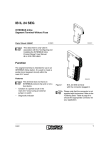
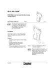
IB IL 24 MUX MA (-PAC)
US
UMX
Inline field multiplexer
MU
UL
ST
CE E
R
LE
4x
Data sheet
5985_en_06
© PHOENIX CONTACT - 10/2008
–
–
ne
–
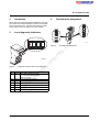
Remote bus connections in copper technology (can be
operated via fiber optics using an interface converter)
Can supply a field multiplexer station with all of the
required 24 V voltages
Floating alarm output ("N/C" relay contact) for
connecting alarm signals
Connection establishment and comparison of the I/O
configuration of both stations
Diagnostic indications via LEDs
Hardware version 15 or later:
Approved for use in zone 2 potentially explosive areas
(observe the notes on page 9)
s.
The field multiplexer is the central unit of a field multiplexer
station. All Inline I/O terminals are connected to it. The field
multiplexer exchanges data with the opposite station via a
remote bus cable.
co
Features
Description
nt
1
m
AUTOMATION
–
–
on
l
in
ec
om
po
–
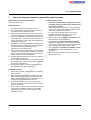
This data sheet is only valid in association with the IL SYS INST UM E user manual.
Please refer to the IB IL MUX UM E user manual for further information on the field multiplexer.
You will find a list of I/O terminals that can be operated on the field multiplexer in the AH IL BK IO LIST application
note. See "Ordering data" on page 2.
Make sure you always use the latest documentation.
It can be downloaded at www.download.phoenixcontact.com.
This data sheet is valid for the products listed on the following page:
IB IL 24 MUX MA (-PAC)
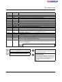
2
Ordering data
Products
Description
Type
Order No.
Field multiplexer, complete with accessories (connectors and labeling fields)
IB IL 24 MUX MA-PAC
2861205
1
Field multiplexer, without accessories
IB IL 24 MUX MA
2718413
1
Pcs./Pkt.
The listed connector set is needed for the complete fitting of the IB IL 24 MUX MA.
Type
Connector set for the field multiplexer
IB IL MUX-PLSET
Keying profile
CP-MSTB
see COMBICON catalog
Zack marker strip to label the terminals
ZBF 6 ...
see CLIPLINE catalog
ZBF 12 ...
see CLIPLINE catalog
DIN EN 50022 DIN rail, 2 meters
NS 35/7,5 PERFORATED
NS 35/7,5 UNPERFORATED
m
Accessories
Description
Order No.
Pcs./Pkt.
1
1734634
100
0801733
0801681
1
1
nt
s.
co
2836036
3022276
50
E/AL-NS 35
1201662
50
Adapter cable between field multiplexer and PSI interface converter
IB IL MUX-CAB PSI
2878476
1
Order No.
Pcs./Pkt.
po
Standard end clamp; snapped on without tools
ne
CLIPFIX 35-5
End clamp for use in the event of vibrations or installation on vertical DIN rail;
secured with screws
om
Accessories: Additional system components
Description
Type
See TRABTECH catalog
Fiber optic interface converters
for fiber optic data transmission
See INTERFACE catalog
in
ec
Surge protection
for protection of the remote bus cable, the power supply units, and the entire
control cabinet by fuses
See INTERFACE catalog
Power supply units
to supply the field multiplexer stations
See INTERFACE catalog
End clamps, grounding clamps, and shield connection clamps
See CLIPLINE catalog
on
l
Temperature measuring transducer
to acquire temperature values
Cables suitable for copper or fiber optic transmission
See INTERFACE or AUTOMATION catalog
Documentation
Description
Type
Order No.
Pcs./Pkt.
"Automation terminals of the Inline product range" user manual
IL SYS INST UM E
2698737
1
"Configuring and installing the Inline field multiplexer" user manual
IB IL MUX UM E
2718439
1
"Summary of key data for Inline devices" data sheet
DB GB IB IL DEVICE LIST
9007007
1
"I/O modules at bus couplers“ application note
AH IL BK IO LIST
9015358
1
–
–
"Inline terminals for use in zone 2 potentially explosive areas" application note AH EN IL EX ZONE 2
5985_en_06
PHOENIX CONTACT
2
IB IL 24 MUX MA (-PAC)
3
Technical data
General data
Housing dimensions (width x height x depth)
48.6 mm x 136 mm x 72 mm (with connector set)
Weight
146 g (without connectors), 212 g (with connectors)
Ambient temperature (operation)
-25°C to 55°C
Ambient temperature (storage)
-25°C to +85°C
Humidity (operation/storage/transport)
10% to 95% according to EN 61131-2
Air pressure (operation/storage/transport)
70 kPa to 106 kPa (up to 3000 m above sea level)
IP20
Class 3 according to EN 61131-2, IEC 61131-2
Housing material
Basic material: ARNITE plastic
PA6.6, self-extinguishing (V0)
m
Degree of protection
Degree of protection
2; condensation not permitted during operation
Surge voltage class
II (low-level signal)
Connection data for Inline connectors
co
Pollution degree according to EN 50178
Spring-cage terminals
Conductor cross-section
0.08 mm2 to 1.5 mm2 (solid or stranded), 28 - 16 AWG
s.
Connection method
nt
System data
63, maximum
Number of I/O points per station
512 digital or 32 analog I/Os, maximum, can be mixed
Update time for all inputs/outputs
ne
Number of devices per station
1 s, maximum
Maximum field multiplexer current for supplying the logic of I/O terminals
2 A at UL
0.5 A at UANA
po
Maximum additional current for supplying the analog terminals
Common data for 24 V main supply, segment supply, and field multiplexer supply
Through Inline connector; terminal point assignment see page 7
Connection method
Recommended cable lengths
Continuation
Nominal value
Ripple
Spring-cage terminals
30 m, maximum; routing cables through outdoor areas is not admissible
Via potential routing
The field multiplexer supply UMUX is electrically isolated from UM/US if it is
supplied separately. This is only ensured if two separate power supplies are
used.
24 V DC
± 5%
19.2 V to 30 V (ripple included)
on
l
Permissible range
in
ec
Special demands on the power supply
om
Connection
NOTE: Module damage due to overload
Each 24 V area must be protected externally. The power supply unit must be able to supply 4 times (400%) the nominal current of the external
fuse, to ensure that the fuse blows safely in the event of an error.
Observe the current consumption of every device on the individual potential jumpers when configuring a field multiplexer station. It is specified
in every terminal-specific data sheet. The current consumption can differ depending on the individual terminal. If the maximum current
carrying capacity of a potential jumper is reached, a new power terminal must be used.
24 V main supply (UM)/24 V segment supply (US)
Current carrying capacity
8 A, maximum
WARNING: Explosion hazard, restrictions regarding the Inline system
When using the terminal in potentially explosive areas, observe the limitations on the current carrying capacity (see "Notes on using the
terminal in potentially explosive areas" on page 9).
5985_en_06
PHOENIX CONTACT
3
IB IL 24 MUX MA (-PAC)
24 V field multiplexer supply (UMUX)
Current consumption at UMUX
Minimum current consumption at nominal voltage
60 mA (no local bus devices connected)
Maximum current consumption at nominal voltage
1,25 A
Consisting of
0.060 A
+ 0.690 A
+ 0.5 A
Current consumption of field multiplexer, electronics
Communications power for all I/O terminals
Supply for the analog terminals
The field multiplexer supply UMUX (24 V) generates the communications power UL (7.5 V) and the analog supply UANA (24 V).
7.5 V DC
co
Nominal value
m
Communications power (UL) and analog supply (UANA)
Communications power (potential jumpers)
Maximum output current
2 A DC (observe derating)
Safety equipment
Electronic short-circuit protection
24 V DC
nt
Nominal value
s.
Analog supply (potential jumpers)
0.5 A DC (observe derating)
Safety equipment
Electrical short-circuit protection
ne
Maximum output current
po
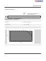
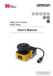
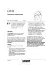
Derating of the communications power and the analog terminal supply
- I/O supply with a current carrying capacity at the bus coupler of 8 A, maximum
100
om
90
80
70
in
ec
P [%]
60
50
40
30
on
l
20
10
0
0
5
10
15
20
25
30
35
40
45
50
TA [°C]
P [%]
Current carrying capacity of the communications power (UL) and the analog supply (UANA) in %
TA [°C]
Ambient temperature in °C
5985_en_06
55
5520A012
PHOENIX CONTACT
4
IB IL 24 MUX MA (-PAC)
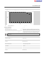
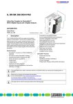
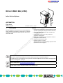
Derating of the communications power and the analog terminal supply
- I/O supply with a current carrying capacity at the bus coupler of 4 A, maximum
100
90
80
70
50
40
m
P [%]
60
30
co
20
10
0
5
10
15
20
25
30
35
40
45
50
Current carrying capacity of the communications power (UL) and the analog supply (UANA) in %
TA [°C]
Ambient temperature in °C
ne
P [%]
Surge voltage (segment supply US/main supply UM/
field multiplexer supply UMUX)
om
Polarity reversal (segment supply US/main supply UM)
Input protective diodes (can be destroyed by permanent overload)
po
Protective equipment
Polarity reversal (field multiplexer supply UMUX)
55
5520A013
nt
TA [°C]
s.
0
Pulse loads up to 1500 W are short circuited by the input protective diode.
Parallel diodes for protection against polarity reversal; in the event of an error
the high current through the diodes causes the preconnected fuse to blow.
Serial diode in the lead path of the power supply; in the event of an error only
a low current flows. In the event of an error, no fuse trips within the external
power supply. Ensure 2 A fuse protection to the external power supply.
Electrical isolation
in
ec
The field multiplexer supply is protected against polarity reversal and surge voltage. These protective elements are only used to protect the
power supply unit.
on
l
RS-485 interface/supply voltage
RS-485 interface/local bus
Interfaces
Remote bus
Connection
500 V AC, 1 min.
500 V AC, 1 min.
Inline shield connector
Interface type
RS-485, modified
Transmission protocol
Special remote control protocol
Remote bus length (copper)
12 km, maximum and 5 km, typical
(depending on cable type and EMC environmental conditions)
Remote bus length (fiber optic)
Using fiber optic converters
– Polymer fiber
Up to 100 m
– HCS fiber
Up to 2400 m
– Multi-mode glass fiber
Up to 25 km
– Single-mode glass fiber
Up to 45 km
Local bus
Connection
5985_en_06
Inline data routing
PHOENIX CONTACT
5
IB IL 24 MUX MA (-PAC)
Local functions
Alarm output (floating contacts)
N/C relay contact for 24 V DC/1 A, typical
Maximum contact power: 30 W DC or 60 VA AC
Maximum contact voltages: 150 V DC or 125 V AC
(A maximum switching current of 1 A must not be exceeded)
Observe high inrush currents when using lamps as alarm signals. Phoenix Contact recommends avoiding lamp loads greater than
24 V/40 mA.
Mechanical requirements
2g, according to IEC 60068-2-6, criterion 1
Vibration (storage)
2g, according to IEC 60068-2-6
Shock (operation)
15g, according to IEC 60068-2-27, criterion 2
m
Vibration (operation)
EN 61000-4-2/
IEC 61000-4-2
Criterion B
Electromagnetic fields
EN 61000-4-3
IEC 61000-4-3
Criterion A
Fast transients (burst)
EN 61000-4-4/
IEC 61000-4-4
Criterion A
Surge voltage
EN 61000-4-5/
IEC 61000-4-5
Conducted interference
EN 61000-4-6
IEC 61000-4-6
nt
s.
6 kV contact discharge
8 kV air discharge
ne
Field strength: 10 V/m
po
Electrostatic discharge (ESD)
co
Conformance with EMC directive 2004/108/EC
Noise immunity test according to DIN EN 61000-6-2
All interfaces: 1 kV
Criterion B
DC supply lines: 0.5 kV/0.5 kV (symmetrical/asymmetrical)
Signal cables: 1.0 kV/2.0 kV (symmetrical/asymmetrical)
Criterion A
Test voltage 10 V
om
Noise emission test according to EN 61000-6-4
Noise emission of housing
EN 55011
in
ec
Approvals
Class A
on
l
For the latest approvals, please visit www.download.phoenixcontact.com or www.eshop.phoenixcontact.com.
5985_en_06
PHOENIX CONTACT
6
IB IL 24 MUX MA (-PAC)
4
Connection
6
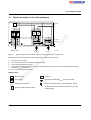
Terminal point assignment
An end plate is provided with the field multiplexer. Place this
plate at the end of the field multiplexer station. The end plate
has no electrical function. It protects the station from ESD
pulses and the user from dangerous contact voltage.
1
1
U L
S T
U S
R E
U M
C E
L E
1
2 .1
1 .2
2
2
2 .2
3
3
2 .3
4
4
2 .4
1 .1
1
1
2 .1
1 .2
2
2
2 .2
1 .4
1 .3
3
3
2 .3
1 .4
4
4
Figure 2
2 .4
5 9 8 1 A 0 1 9
Terminal point assignment
po
5 9 8 5 B 0 0 3
5985_en_06
in
ec
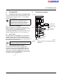
Color Meaning
Green 24 V field multiplexer supply/
7.5 V communications power/
interface supply
Red Field multiplexer stopped
Red Configuration error
Red Remote bus error
Red Local bus error
Green 24 V segment supply
Green 24 V main supply
on
l
ST
CE
RE
LE
US
UM
Diagnostic indicators of the field multiplexer
om
Figure 1
Des.
UL
ne
nt
s.
M U X
1
1 .3
m
Local diagnostic indicators
1 .1
co
5
2
2
PHOENIX CONTACT
7
IB IL 24 MUX MA (-PAC)
Terminal
point
Connector 1
1.1, 2.1
1.2
2.2
1.3, 2.3
1.4, 2.4
Connector 2
Assignment Remark
om
po
ne
nt
s.
co
m
Remote bus, configuration of transmission mode (copper/fiber optics)
Configuration of transmission mode (copper/fiber optics)
CONFFO
DATA
Differential signal, data line to the opposite station (remote bus)
/DATA
Differential signal, data line to the opposite station (remote bus)
Reference potential for DATA and /DATA
GNDDATA
Shield
Shield potential of the data line (remote bus)
No function
Cover for unused terminal points
Connector 3 Floating alarm contact, UMUX supply, master/slave configuration
1.1
Alarm_IN
Alarm contact (floating, closed in the event of an error)
2.1
Alarm_OUT Alarm contact (floating, closed in the event of an error)
Field multiplexer supply (24 V DC)
1.2, 2.2
UMUX
GND for field multiplexer supply
1.3, 2.3
GNDMUX
The potential is reference ground for the field multiplexer electronics
Master/slave configuration
1.4, 2.4
CONFMA
Connector 4 Power connector (UM / US)
24 V segment supply; the supplied voltage is directly routed to the potential jumper.
1.1, 2.1
US
24 V main supply; the supplied voltage is directly led to the potential jumper.
1.2, 2.2
UM
1.3, 2.3
GND
The reference potential is directly led to the potential jumper and is, at the same time,
reference ground for the main and segment supply.
1.4, 2.4
FE
Connection of the field multiplexer, i.e., of the field multiplexer station to functional earth
ground. The contacts are directly connected to the potential jumper and the FE spring on
the bottom of the housing.
in
ec
Functional earth ground is only used to discharge interference.
on
l
Contacts with identical designations are
electrically connected inside the field multiplexer.
For information on the power supplies, please
refer to the IL SYS INST UM E user manual.
5985_en_06
NOTE: Overload
The maximum total current through the potential
jumpers UM and US is 8 A.
NOTE: Malfunction
Connect the field multiplexer to functional earth
ground via the FE connection of connector 4. For
this, connect the corresponding contact with a
grounding terminal (see also Figure 3 on
page 10).
PHOENIX CONTACT
8
IB IL 24 MUX MA (-PAC)
7
Notes on using the terminal in potentially explosive areas
Approval according to directive 94/9/EC
Restrictions/limit values
X II 3 G Ex nAC IIC T4 X
1.
6.
7.
8.
Installation in zone 2
2.
3.
4.
5.
m
co
Observe the specified conditions for use in potentially
explosive areas.
When installing the terminal, use an appropriate and
approved housing with a minimum protection of IP54.
Please observe the EN 60079-14 requirements, e.g., a
steel housing with a wall thickness of 3 mm.
In potentially explosive areas, only snap the Inline
terminal onto the rail and connect the cables when the
power is switched off.
In zone 2, only connect devices to the supply and signal
circuits that are suitable for operation in potentially
explosive areas of zone 2 and the conditions at the
installation location.
5985_en_06
on
l
1.
4.
nt
5.
3.
ne
4.
2.
po
3.
om
2.
This Inline terminal can be installed in zone 2.
The Inline terminal must only be installed, operated,
and maintained by qualified personnel.
Please follow the installation instructions given in the
IL SYS INST UM E user manual and the package slip.
Observe all applicable safety directives (even national
safety regulations), accident prevention regulations, as
well as general rules of technology when installing and
operating the equipment.
Please refer to the corresponding documentation (user
manual, data sheet, package slip) and the certificates
(EC type examination and other approvals, if
applicable) for safety-related data.
It is not permitted to access the circuits inside the Inline
terminal. Do not repair the Inline terminal by yourself but
replace it with a terminal of the same type. Repairs may
only be carried out by the manufacturer.
IP20 (EN 60529) protection of the device is provided for
a clean and dry environment.
Do not subject the Inline terminal to mechanical strain
and thermal loads, which exceed the limits specified in
the product documentation.
The Inline terminal has not been designed for use in
dust potentially explosive atmospheres.
in
ec
–
1.
s.
Installation notes
Only Inline terminals that are approved for use in
potentially explosive areas may be snapped next
to this Inline terminal.
Before using an Inline terminal in a zone 2 potentially
explosive area, first check that the terminal has been
approved for installation in this area.
For a list of terminals approved for use in zone 2
potentially explosive areas, please refer to the
AH EN IL EX ZONE 2 application note.
Please ensure that the supplies of UM and US at the
field multiplexer do not exceed 4 A.
Please make sure that the maximum permissible
current of 4 A flowing through potential jumpers UM
and US (total current) is not exceeded when using the
Inline terminals in potentially explosive areas.
Also ensure that the maximum permissible current
of 2 A flowing through potential jumper UL is not
exceeded.
The maximum permissible current for each tension
spring contact is 2 A.
PHOENIX CONTACT
9
IB IL 24 MUX MA (-PAC)
8
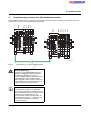
Configuration
9
8.1
Configure the"fiber optics" transmission mode
Connection example
Connector 1
2
3
4
If you want to implement fiber optic data transmission, insert
a cable jumper at connector 1 from 1.1 to 2.1 (CONFFO)
(see Figure 3 on page 10).
UL
1
FO
Alarm contact
po
8.4
om
Please refer to Section 3 "Technical data" for
information on the alarm contact rating.
1
2
1
1
11
11
11
2
22
22
22
3
33
4
44
ne
The field multiplexer has a floating alarm output (Alarm_IN
and Alarm_OUT contacts at connector 3) that allows to
indicate operating errors remotely. The contact is normally
open, but it is closed in the event of an error and when the
field multiplexer power supply fails.
2
2
ALARM
1
2
33
33
3
44
44
4
nt
8.3
1
+
-
Alarm signals
+
-
Possible 24 V
segment supply
(US)
24 V main
supply (UM)
s.
The second station must be configured as a slave. It must
not have a cable jumper from 1.4 to 2.4. at connector 3.
2
+
One field multiplexer station must be configured as the
master. To do this, insert a cable jumper at connector 3 from
1.4 to 2.4 (CONFMA) (see Figure 3 on page 10).
MUX
co
Master/slave configuration
UM
m
Ensure that the same transmission mode
(copper/fiber optic) is always set on the field
multiplexer station and the opposite station.
8.2
US
ST
CE
RE
LE
NOTE: Malfunction
Master
24 V field multiplexer
supply (UMUX)
Remote bus
Figure 3
-
5985A008
Typical connection of the cables to the field
multiplexer
Connecting the remote bus cable
on
l
in
ec
For interference-free transmission, Phoenix Contact
recommends that you use a shielded cable. In this case,
connector 1 of both stations should be connected to the
DATA, /DATA, and GNDDATA signals and the shield (see
also Figure 3 on page 10). In addition, the cables for DATA
and /DATA must be twisted-pair cables.
5985_en_06
PHOENIX CONTACT
10
IB IL 24 MUX MA (-PAC)
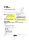
Electrical isolation in the field multiplexer
Local bus
UL+
UANA
UL-
mC
1
4
5V
5V
24 V
24 V
7.5 V
24 V
+24 V (UM)
2
2
Remote bus
5985D001
UMUX
(UL/UANA)
UM/US
ne
Figure 4
nt
3
s.
1
+24 V (US)
co
5
m
10
Electrical isolation of the individual function areas (separate power supply units)
po
Potential areas when using separate power supply units to supply UMUX and UM/US:
Area of remote bus cable
Area of functional earth ground (FE) capacitive for shield
Area of functional earth ground (FE)
Area of the field multiplexer supply UMUX from which the communications power UL and the supply for the analog
terminals UANA are generated
Area of the I/O voltages UM and US
5
μC
on
l
Symbols used:
in
ec
om
1
2
3
4
Microcontroller
Optocoupler
Electrically isolated area
Supply unit with electrical isolation
5985_en_06
Converter
1
2
Reference potential GNDDATA (remote bus cable)
Reference potential GNDMUX (field multiplexer supply)
Shield potential; connected with a capacitor to FE of the
potential jumper
PHOENIX CONTACT
11
IB IL 24 MUX MA (-PAC)
11
Complementary structure of a field multiplexer system
D O
U S
U M
L E
1
3
M U X
D I4
2
D
1
4
2
D
1
D I2
2
D
D O 2
2
1
2
1
2
1
2
1
1
2
2
1
2
1
2
C E
S T
U S
R E
U M
L E
1 1
1 1
1 1
1 1
1 1
1 1
1 1
1
2
2 2
2 2
2 2
2 2
2 2
2 2
2 2
2
1
2
1
1 1
3 3
3 3
3 3
3 3
3 3
3 3
3 3
3
4
4 4
4 4
4 4
4 4
4 4
4 4
4 4
4
2
2 2
3
3 3
4
4 4
1
1 1
2
1
1 1
ne
D O 4
2
D
1
4
D O 2
2
D
1
2
D
D
D I2
A O 1
2
1
2
1
1 1
2
1
2
1
2
D
A O 1
1
2
1 1
1 1
1 1
1
2 2
2 2
2 2
2 2
2 2
2 2
2 2
2
3 3
3 3
3 3
3 3
3 3
3 3
3 3
3
4 4
4 4
4 4
4 4
4 4
4 4
4 4
4
1 1
5
5
6
6
5 9 8 5 A 0 0 7
om
po
6
2
nt
3
6
3
M U X
1
5
1
s.
1
5
A O
A I2
U L
1
A O
D
m
S T
R E
co
U L
C E
D I 2
M U X
1
1
2
4
D O
A I 2
D O
D I 2
D I 4
M U X
2
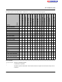
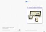
Field multiplexer stations must be created in such a way that each input terminal is assigned to an output module on the
opposite side, and vice versa (complementary arrangement).
Typical structure of a field multiplexer system
in
ec
Figure 5
CAUTION: Malfunction
on
l
Terminals for analog signals must always be
installed to the right of the digital terminals in a
field multiplexer station. If this rule is not
observed, the field multiplexer station will report a
configuration error, and the field multiplexer
system will not be ready-to-operate. In the event
of subsequent extension, digital terminals must
be inserted before the analog terminals.
You will find a list of I/O terminals that can be
operated in the AH IL BK IO LIST application
note. Terminal combinations other than the ones
listed in the table below are not permitted and will
be detected as a configuration error. The
IB IL AI 2/SF-PAC analog terminal can also be
combined with two IB IL AO 1... terminals, see
also "Possible combinations of analog I/O
terminals" on page 14.
5985_en_06
PHOENIX CONTACT
12
IB IL 24 MUX MA (-PAC)
IB IL 24 DI 4-PAC
IB IL 24 DI 8-PAC
1
1
–
–
IB IL 24 DO 2-PAC
2
2
2
1
1
2
2
–
–
IB IL 24 DO 2-2A-PAC
2
2
2
1
1
2
2
–
–
IB IL 24 DO 2-2A-NPN-PAC
2
2
2
1
1
2
2
IB IL 24 DO 4-PAC
–
–
–
–
–
IB IL 24 DO 8-PAC
–
–
–
–
–
IB IL 24 DO 8-2A-PAC
–
–
–
–
IB IL 24 DO 16-PAC
–
–
–
–
IB IL 24 DO 32/HD-PAC
–
–
–
IB IL 24/230 DOR 1/W-PAC
(1)+
(1)+
IB IL 24/230 DOR 1/W-PCPAC
(1)+
(1)+
–
–
–
–
–
–
–
–
–
–
2
–
–
–
–
–
2
–
–
–
–
–
2
s.
–
–
4
–
–
–
–
–
–
–
–
–
–
8
8
–
–
–
–
–
–
–
–
–
8
8
–
–
–
–
–
po
co
m
–
–
–
–
–
–
–
–
16
–
–
–
–
–
–
–
–
–
–
–
–
32
–
–
–
(1)+
1
1
1
1
–
–
–
–
–
–
–
–
(1)+
1
1
1
1
–
–
–
–
–
–
–
–
om
in
ec
IB IL 24 SAFE 1-PAC
IB IL 24 DI 2-NPN-PAC
1
IB IL AI 2/SF-230-PAC
IB IL 24 DI 2-PAC
1
IB IL AI 2/SF-PAC
IB IL 230 DI 1-PAC
(1)+
IB IL 24 DI 32/HD-PAC
IB IL 120 DI 1-PAC
(1)+
IB IL 24 DI 16-PAC
IB IL 24 SEG/F-D-PAC
(1)+
–
nt
ne
Outputs
IB IL 24 DI 8 T2-PAC
IB IL 24 PWR IN/2-F-D-PAC
IB IL DO 1 AC-PAC
Inputs
IB IL 24 PWR IN/F-D-PAC
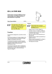
The following matrix shows the possible combinations for a complementary terminal arrangement:
–
–
–
–
–
–
–
4
–
–
–
–
–
–
–
IB IL 24/230 DOR 4/W-PCPAC
–
–
–
–
–
–
–
4
–
–
–
–
–
–
–
2 x IB IL AO 1/SF-PAC
–
–
–
–
–
–
–
–
–
–
–
–
2
2
–
2 x IB IL AO 1/U/SF-PAC
–
–
–
–
–
–
–
–
–
–
–
–
2
2
–
1 x IB IL AO 1/SF -PAC
1 x IB IL AO 1/U/SF-PAC
–
–
–
–
–
–
–
–
–
–
–
–
2
2
–
1 x IB IL AO 2/U/BP-PAC
–
–
–
–
–
–
–
–
–
–
–
–
2
2
–
on
l
IB IL 24/230 DOR 4/W-PAC
Key for the table:
1, 2, 4, 8, 16, 32
Number of available channels
–
Combination not possible
+
Should be operated with the IB IL 24 DO 2-PAC terminal, as only the fuse and not the main power is
monitored.
5985_en_06
PHOENIX CONTACT
13
IB IL 24 MUX MA (-PAC)
Possible combinations of analog I/O terminals
IB IL AI 2/
SF-PAC
IB IL AI 2/
SF-PAC
IB IL AI 2/
SF-PAC
IB IL AI 2/
SF-PAC
IB IL AO 1/
SF-PAC
0 V ... 10 V
IB ILAO 1/SFPAC
0 mA ... 20 mA
IB IL AO 1/U/
SF-PAC
0 V ... 10 V
IB ILAO 2/UBP- IB IL AO 2/UBPPAC
PAC
0 V ... 10 V
-10 V ... +10 V
-10 V ... +10 V
0 V ... 10 V
x
x
x
4 mA ... 20 mA
x
0 mA ... 20 mA
x
Transmission time
nt
= 10 ms to 100 ms
ne
tFO
on
l
in
ec
om
po
= 80 ms to 500 ms
s.
The maximum time required for data transmission depends
on the type of transmission medium that has been selected
and is usually within the following limits:
tCu
x
co
12
Signal
m
Terminal
5985_en_06
PHOENIX CONTACT GmbH & Co. KG • 32823 Blomberg • Germany • Phone: +49-(0) 5235-3-00
PHOENIX CONTACT • P.O.Box 4100 • Harrisburg • PA 17111-0100 • USA • Phone: +717-944-1300
www.phoenixcontact.com
14