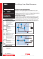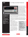
1
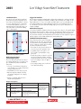
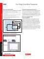
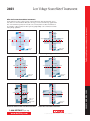
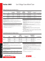
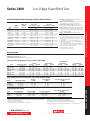
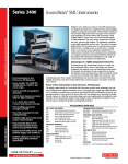
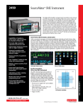
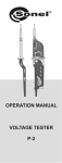
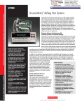
Low Voltage SourceMeter Instrument The economical Model 2401 is the latest member of Keithley’s Series 2400 SourceMeter family, designed specifically for low voltage test applications that demand tightly coupled sourcing and measurement. Like all Series 2400 SourceMeter models, the Model 2401 provides precision voltage and current sourcing and measurement capabilities (1μV–20V and 10pA–1A). It is both a highly stable DC power source and a true instrument-grade 5½-digit multimeter. The power source characteristics include low noise, precision, and readback. The multimeter capabilities include high repeatability and low noise. The result is a compact, single-channel, DC parametric tester. In operation, it can act as a voltage source, a current source, a voltage meter, a current meter, and an ohmmeter. • 1μV–20V and 10pA–1A precision voltage and current sourcing and measurement capabilities • Five instruments in one (IV Source, IVR Measure) • Source and sink (4-quadrant) operation • 0.012% basic measure accuracy with 5½-digit resolution • 2-, 4-, and 6-wire remote V-source and measure sensing • 1700 readings/second at 4½ digits via GPIB • Standard SCPI GPIB, RS-232, and Keithley Trigger Link interfaces • Keithley LabTracer 2.0 I-V curve tracing application software (download) The Lowest Cost Precision SMU (source measurement unit) on the Market The Model 2401 is the lowest cost precision SMU instrument on the market, offering an economical 20W I-V source/measure alternative to configuring systems and test benches with separate programmable power supplies and digital multimeters. The Model 2401 also offers an economical alternative for applications for which precision programmable power supplies cannot deliver sufficient accuracy, signal range, source setting, or readback resolution. The Model 2401 offers users all the same accuracy, speed, and measurement functions as the rest of the instruments in the Series 2400 family. It shares a common operating code base with the rest of the family, so it can be operated and programmed within its range boundaries just like any other Series 2400 instrument. The only functional differences between the Model 2401 and the Model 2400 are that the Model 2401 does not include 200V source and measure ranges or back panel Digital I/O port capabilities. (However, the DB-9 connector is still provided to provide test fixture interlock signals.) Model 2401 Applications Manufacturers of components and modules for the communications, semiconductor, computer, automotive, and medical industries will find the Model 2401 invaluable for a wide range of characterization and production test applications. Its 20V@1A output makes it ideal for characterizing the current-voltage (I-V) performance of photovoltaic (solar) cells, high brightness LEDs (HBLEDs), low voltage materials, CMOS circuits and low-power semiconductor devices, as well as resistance measurements on these devices. The Model 2401 is well suited for use as a gate bias in applications involving devices with three or more terminals such as HBLEDs and photovoltaic cells, reducing total system hardware costs. It also provides sufficient range for characterizing low voltage materials and devices (including graphene and other nano- and MEMs-type structures), which are inherently low voltage oriented. 1.888.KEITHLEY (U.S. only) w w w.keithley.com A G R E A T E R M E A S U R E Typical Applications • High brightness LED (DC and pulse) • Photovoltaic cell efficiency (source and sink) • Precision DC power supply/ current measure • Discrete semiconductor devices • Passive devices • Laser diodes, laser diode modules, LEDs, photodetectors • Connectors, switches, relays • Low voltages/resistances • LIV • IDDQ • I-V characterization O F C O N F I D E N C E Tightly coupled precision Sidesourcing Text and measurement ® SOURCE AND MEASURE 2401 2401 Ordering Information Tightly coupled precision Sidesourcing Text and measurement 2401 Low Voltage SourceMeter® Instrument Accessories Supplied Model 8605 Test Leads LabVIEW Software Driver (downloadable) ACCESSORIES AVAILABLE TEST LEADS 1754 5804 5805 5808 5809 8607 CA-18-1 AND PROBES 2-Wire Universal 10-Piece Test Lead Kit Kelvin (4-Wire) Universal 10-Piece Test Lead Kit Kelvin (4-Wire) Spring-Loaded Probes Low Cost Single-pin Kelvin Probe Set Low Cost Kelvin Clip Lead Set 2-Wire, 1000V Banana Cables, 1m (3.3 ft) Shielded Dual Banana Cable, 1.2m (4 ft) SWITCHING 7001 7002 7019-C 7053 HARDWARE Two-Slot Switch System Ten-Slot Switch System 6-Wire Ohms Switch Card High-Current Switch Card ® Advantages of a Tightly Integrated Instrument By linking source and measurement circuitry in a single unit, the Model 2401 offers a variety of advantages over systems configured with separate source and measurement instruments. For example, it minimizes the time required for test station development, setup, and maintenance, while lowering the overall cost of system ownership. It simplifies the test process itself by eliminating many of the complex synchronization and connection issues associated with using multiple instruments. Its compact half-rack size conserves precious “real estate” in the test rack or bench. Much More than a Power Supply The tightly coupled nature of a SourceMeter instrument provides many advantages over solutions configured from separate instruments such as a precision power supply and a digital multimeter. For example, the Model 2401 provides faster test times by reducing GPIB traffic and simplifies the remote programming interface. It also protects the device under test from damage due to accidental overloads, thermal runaway, etc. Both the Model 2401’s current and voltage source are programmable with readback to help maximize device measurement integrity. If the readback reaches a programmed compliance limit, then the source is clamped at the limit, providing fault protection. Imeter Triggering and Control 8501-1 Trigger Link Cable, DIN-to-DIN, 1m (3.3 ft) 8501-2 Trigger Link Cable, DIN-to-DIN, 2m (6.6 ft) 8502 Trigger Link to BNC Breakout Box 8503 Trigger Link Cable, DIN-to-Dual BNC, 1m (3.3 ft) 8505 Male to 2-Female Y-DIN Cable for Trigger Link RACK MOUNT KITS 4288-1 Single Fixed Rack Mount Kit 4288-2 Dual Fixed Rack Mount Kit 4288-4 Dual Fixed Rack Mount Kit 4288-5 Shelf Type Side by Side Rack Mounting Kit 4288-9 Dual Fixed Rack Mounting Kit Services Available TRN-2400-1C 1-year factory warranty extended to 3 years from date of shipment Course: Unleashing the Power of Your SourceMeter Instrument 1.888.KEITHLEY (U.S. only) w w w.keithley.com IN/OUT HI Remote SENSE HI DUT Vmeter/Compliance Remote SENSE LO Local IN/OUT LO Source I, Measure V, I, or W configuration Imeter/Compliance Local IN/OUT HI Remote SENSE HI Vmeter Vsource DUT Feedback to Adjust Vsource Software LabTracer 2.0 Curve Tracing Software (downloadable) 2401-3Y-EW Local Isource CABLES/ADAPTERS 7007-1 Shielded GPIB Cable, 1m (3.3 ft) 7007-2 Shielded GPIB Cable, 2m (6.6 ft) 7009-5 RS-232 Cable 8620 Shorting Plug Communication Interface KPCI-488LPA IEEE-488 Interface/Controller for the PCI Bus KUSB-488B IEEE-488 USB-to-GPIB Interface Adapter SOURCE AND MEASURE Low Voltage SourceMeter Instrument Remote SENSE LO Local IN/OUT LO Source V, Measure I, V, or W configuration A G R E A T E R M E A S U R E O F C O N F I D E N C E 2401 Low Voltage SourceMeter Instrument I-V Characteristics Like all Series 2400 SourceMeter instruments, the Model 2401 provides four-quadrant operation. In the first and third quadrants, it operates as a source, delivering power to a load. In the second and fourth quadrants, it operates as a sink, dissipating power internally. Voltage, current, and resistance can be measured during source or sink operation. Trigger Link Interface All SourceMeter instruments include Keithley’s unique Trigger Link interface, which provides high speed, seamless communications with many of Keithley’s other instruments. For example, use the Trigger Link interface to connect a SourceMeter instrument with a Series 7000 Switching System for a complete multipoint test solution. With Trigger Link, Series 7000 Switching Systems can be controlled by a SourceMeter instrument during a high speed test sequence independent of a computer and GPIB. +100mA –200V –20V +20V +200V –100mA Duty cycle limited –1A Model 2401 four-quadrant operation Built-In Test Sequencer (Source Memory List) The Source Memory list provides faster and easier testing by allowing you to set up and execute up to 100 different tests that run without PC intervention. • Stores up to 100 instrument configurations, each containing source settings, measurement settings, pass/fail criteria, etc. • Pass/fail limit test as fast as 500µs per point • Onboard comparator eliminates the delay caused when sending data to the computer for analysis • Built-in, user-definable math functions to calculate derived parameters Standard and Custom Sweeps Sweep solutions greatly accelerate testing with automation hooks. Three basic sweep waveforms are provided that can be programmed for singleevent or continuous operation. They are ideal for I/V, I/R, V/I, and V/R characterization. • Linear Staircase Sweep: Moves from the start level to the stop level in equal linear steps • Logarithmic Staircase Sweep: Done on a log scale with a specified number of steps per decade • Custom Sweep: Allows construction of special sweeps by specifying the number of measurement points and the source level at each point • Up to 1700 readings/second at 4½ digits to the GPIB bus • 5000 5½-digit readings can be stored in the non-volatile buffer memory Stop Start Bias Bias Linear staircase sweep Stop Start Bias Bias Logarithmic staircase sweep Stop Start User defined steps Bias Bias Custom sweep I Example Test Sequence Test Pass/Fail Test If Passes Test If Fails Test Test 1 Check V F1 at 100mA against pass/fail limits Go to Test 2 Test 2 Check V F2 at 1A against pass/fail limits Go to Test 3 Test 3 Check leakage current at –500V and test against pass/fail limits 1.Bin part to good bin 2.Transmit readings to computer while handler is placing new part 3.Return to Test 1 1.Bin part to bad bin 2.Transmit data to computer while handler is placing new part 3.Return to Test 1 1.888.KEITHLEY (U.S. only) w w w.keithley.com A G R E A T E R VF2 VF1 Test 2 Test 1 IR Test 3 M E A S U R E O F C O N F I D E N C E V SOURCE AND MEASURE +1A Automation for Speed A SourceMeter instrument streamlines production testing. It sources voltage or current while making measurements without needing to change connections. It is designed for reliable operation in nonstop production environments. To provide the throughput demanded by production applications, the SourceMeter instrument offers many built-in features that allow it to run complex test sequences without computer control or GPIB communications slowing things down. Tightly coupled precision sourcing and measurement ® 2401 Low Voltage SourceMeter Instrument ® Tightly coupled precision sourcing and measurement Unique 6-Wire Ohms Technique The Model 2401 can make standard 4-wire, split Kelvin, and 6-wire, guarded ohms measurements and can be configured for either the constant current or constant voltage method. The 6-wire ohms technique: Advantages of a Tightly Integrated Instrument By linking source and measurement circuitry in a single unit, these instruments offer a variety of advantages over systems configured with separate source and measurement instruments. For example, they minimize the time required for test station development, setup, and maintenance, while lowering the overall cost of system ownership. They simplify the test process itself by eliminating many of the complex synchronization and connection issues associated with using multiple instruments. And, their compact half-rack size conserves precious “real estate” in the test rack or bench. • Uses guard and guard sense leads in addition to the 4-wire sense and source leads • Locks out parallel current paths when measuring resistor networks or hybrid circuits to isolate the component under test Power of Five Instruments in One (IV Source, IVR Measure) The tightly coupled nature of a SourceMeter instrument provides many advantages over separate instruments. For example, it provides faster test times by reducing GPIB traffic and simplifies the remote programming interface. It also protects the device under test from damage due to accidental overloads, thermal runaway, etc. Both the current and voltage source are programmable with readback to help maximize device measurement integrity. If the readback reaches a programmed compliance limit, then the source is clamped at the limit, providing fault protection. • Allows users to configure and plot data easily from Series 2400 SourceMeter instruments, making characterization of 2-, 3-, and 4-terminal devices a snap + GUARD GUARD SENSE Imeter IN/OUT HI Unlike narrow-performance SMU platforms, including board-level products, which often deliver sub-optimal analog measurements due to significant loss in signal integrity, accuracy, power, and/or speed due to interconnect, thermal management, and other issues, all Series 2400 SourceMeter instruments combine the industry’s widest dynamic range with uncompromising throughput and superior measurement integrity. SENSE HI DUT R2 Isource Vmeter R1 R3 SENSE LO IN/OUT LO SOURCE AND MEASURE 6-Wire Ohms Circuit. All test current flows through R1 because the high current guard drives the voltage across R2 to 0V. Free LabTracer 2.0 device characterization software (downloadable). 1.888.KEITHLEY (U.S. only) w w w.keithley.com A G R E A T E R M E A S U R E O F C O N F I D E N C E 2401 Low Voltage SourceMeter Instrument Other Series 2400 SourceMeter Instruments If your application requires a wider sourcing or measurement range than the Model 2401 can provide, other Series 2400 instruments likely offer the range you need. Consult the range graphs shown here or the instrument specifications for details. Series 2600A System SourceMeter instruments are also available to address applications that require integrating multiple source and measure channels and/or pulsing capabilities. +1A +1A +200mA +100mA +20mA –200V –20V +20V 2400 only +200V –1100V –200V –20V +20V 2400 only +200V +1100V –20mA –100mA –100mA Duty cycle limited –1A Model 2400 and 2400-LV SourceMeter Instruments. –60V –20V –1A Model 2410 High-Voltage SourceMeter Instrument. +3A +3A +1A +1A +100mA +100mA +20V +60V –100V –60 –20 +20 +60 +100V –100mA –1A –3A Duty cycle limited Tightly coupled precision sourcing and measurement ® –100mA –1A Duty cycle limited Duty cycle limited –3A Model 2420 3A SourceMeter Instrument. Model 2425 100W SourceMeter Instrument. +10A 5A +3A 3A +1A –100V –60 –20 +20 +60 +100V 100mA +10V –10V –40V –100mA –100mA –1A –3A –10A 40V –1A Duty cycle limited Pulse mode only Model 2430 1kW Pulse Mode SourceMeter Instrument. 1.888.KEITHLEY (U.S. only) w w w.keithley.com -–3A Duty cycle limited -5A Model 2440 5A SourceMeter Instrument. A G R E A T E R M E A S U R E O F C O N F I D E N C E SOURCE AND MEASURE 1A +100mA Series 2400 Low Voltage SourceMeter Line ® Voltage Accuracy (Local or Remote Sense) Model Series 2400 condensed Side Text specifications 2400, 2400-C 2401 Range 200.000mV 2.00000V 20.0000V 200.000V 200.000mV 2.00000V 20.0000V Programming Resolution 5µV 50µV 500µV 5mV 5µV 50µV 500µV Source1 Accuracy (1 Year) 23°C ±5°C ±(% rdg. + volts) 0.02% + 600 µV 0.02% + 600 µV 0.02% + 2.4 mV 0.02% + 24 mV 0.02% + 600 µV 0.02% + 600 µV 0.02% + 2.4 mV Default Measurement Resolution 1 µV 10 µV 100 µV 1 mV 1 µV 10 µV 100 µV Temperature Coefficient (0°–18°C and 28°–50°C): ±(0.15 × accuracy specification)/°C. Voltage Regulation: Line: 0.01% of range. Load: 0.01% of range + 100µV. Over Voltage Protection: User selectable values, 5% tolerance. Factory default = none. Current Limit: Bipolar current limit (compliance) set with single value. Min. 0.1% of range. Overshoot: <0.1% typical (full scale step, resistive load, 10mA range). Measurement 2, 3, 4 Accuracy (1 Year) 23°C ±5°C ±(% rdg. + volts) 0.012% + 300µV 0.012% +300µV 0.015% + 1.5 mV 0.015% + 10 mV 0.012% + 300µV 0.012% +300µV 0.015% + 1.5 mV Output Slew Rate (±30%) Source/Sink Limit 0.08 V/µs 0.5 V/µs ±21 V @ ±1.05 A ±210 V @ ±105 mA ±21 V @ ±1.05 A 0.08 V/µs ADDITIONAL SOURCE SPECIFICATIONS (All Models) TRANSIENT RESPONSE TIME: 30µs minimum for the output to recover to its spec. following a step change in load. COMMAND PROCESSING TIME: Maximum time required for the output to begin to change following the receipt of :SOURce:VOLTage|CURRent <nrf> command. Autorange On: 10ms. Autorange Off: 7ms. OUTPUT SETTLING TIME: Time required to reach 0.1% of final value after command is processed. 100µs typical. Resistive load. 10µA to 100mA range. DC FLOATING VOLTAGE: Output can be floated up to ±250VDC (Model 2440 ±40VDC) from chassis ground. REMOTE SENSE: Up to 1V drop per load lead. COMPLIANCE ACCURACY: Add 0.3% of range and ±0.02% of reading to base specification. OVER TEMPERATURE PROTECTION: Internally sensed temperature overload puts unit in standby mode. RANGE CHANGE OVERSHOOT: Overshoot into a fully resistive 100kW load, 10Hz to 1MHz BW, adjacent ranges: 100mV typical, except 20V/200V (20V/60V on Model 2420), 20V/100V on Model 2425 and 2430, range boundary, and Model 2440. MINIMUM COMPLIANCE VALUE: 0.1% of range. NOTES 1. 2400, 2410 Only: Specifications valid for continuous output currents below 105mA. For operation above 105mA continuous for >1 minute, derate accuracy 10%/35mA above 105mA. 2. Speed = Normal (1 PLC). For 0.1 PLC, add 0.005% of range to offset specifications, except 200mV, 1A, 10A ranges, add 0.05%. For 0.01 PLC, add 0.05% of range to offset specifications, except 200mV, 1A, 10A ranges, add 0.5%. 3. Accuracies apply to 2- or 4-wire mode when properly zeroed. 4. In pulse mode, limited to 0.1 PLC measurement. Current Accuracy (Local or Remote Sense) Model SOURCE AND MEASURE 2400, 2400-C, 2401 Range 1.00000µA 10.0000µA 100.000µA 1.00000mA 10.0000mA 100.000mA 1.00000A 2 Programming Resolution 50 pA 500 pA 5 nA 50 nA 500 nA 5 µA 50 µA Source 1, 3 Accuracy (1 Year) 3 23°C ±5°C ±(% rdg. + amps) 0.035% + 600 pA 0.033% + 2 nA 0.031% + 20 nA 0.034% + 200 nA 0.045% + 2 µA 0.066% + 20 µA 0.27 % + 900 µA Temperature Coefficient (0°–18°C and 28°–50°C): ±(0.15 × accuracy specification)/°C. CURRENT Regulation: Line: 0.01% of range. Load: 0.01% of range (except Model 2440 5A range 0.05%) + 100pA. Voltage LIMIT: Bipolar voltage limit (compliance) set with single value. Min. 0.1% of range. OVERSHOOT: <0.1% typical (1mA step, RL = 10kW, 20V range for Model 2400, 2410, 2420, 2425, 2430), (10V range for Model 2440). Source/Sink Limit ±1.05A @ ±21 V NOTES 1. 2400, 2401, 2410 Only: Specifications valid for continuous output currents below 105mA. For operation above 105mA continuous for >1 minute, derate accuracy 10%/35mA above 105mA. 2. Full operation (1A) regardless of load to 30°C (50°C for Model 2420 and 2440). Above 30°C (50°C for Model 2420 and 2440) ambient, derate 35mA/°C and prorate 35mA/W load. 4-wire mode. For current sink operation on 1A, 3A, or 5A ranges, maximum continuous power is limited to approximately 1/2 rated power or less, depending on current, up to 30°C ambient. See power equations in the User’s Manual to calculate allowable duty cycle for specific conditions. 3. For sink mode, 1µA to 100mA range, accuracy is: Model 2400, 2401: ±(0.15% + offset*4). Models 2410, 2420, 2425, 2430, 2440: ±(0.5% + offset*3). For 1A range, accuracy is: Model 2400, 2401: ±(1.5% + offset*8). Models 2410, 2420, 2425, 2430, 2440: ±(1.5% + offset*3). 4. Speed = Normal (1 PLC). For 0.1 PLC, add 0.005% of range to offset specifications, except 200mV, 1A, 10A ranges, add 0.05%. For 0.01 PLC, add 0.05% of range to offset specifications, except 200mV, 1A, 10A ranges, add 0.5%. 5. Accuracies apply to 2- or 4-wire mode when properly zeroed. 6. In pulse mode, limited to 0.1 PLC measurement. Contact Check Specifications (requires -C version) (Not available for Model 2401) Speed: 350µs for verification and notification. Contact Check: 2 W15 W50 W No contact check failure <1.00 W<13.5 W<47.5 W Always contact check failure >3.00 W>16.5 W>52.5 W 1.888.KEITHLEY (U.S. only) w w w.keithley.com Default Measurement Resolution 10 pA 100 pA 1 nA 10 nA 100 nA 1 µA 10 µA Measurement 4, 5, 6 Accuracy (1 Year) 23°C ±5°C ±(% rdg. + amps) 0.029% + 300 pA 0.027% + 700 pA 0.025% + 6 nA 0.027% + 60 nA 0.035% + 600 nA 0.055% + 6 µA 0.22 % + 570 µA A G R E A T E R M E A S U R E O F C O N F I D E N C E Series 2400 Low Voltage SourceMeter Line Resistance Measurement Accuracy (Local or Remote Sense)1, 2, 5 Range Default Resolution Default Test Current 2400, 2401 <0.20000 W3 – – Normal Accuracy (23°C ±5°C) 1 Year, ±(% rdg. + ohms) Enhanced Accuracy (23°C ±5°C) 4 1 Year, ±(% rdg. + ohms) 2400, 2401 2400, 2401 Source I ACC + Meas. VACC Source I ACC + Meas. VACC 2.00000 W3 10µW 20.0000 W 100µW 100mA 0.10% + 0.003W 0.07% + 0.001W 200.000 W 1mW 10mA 0.08% + 0.03 W 0.05% + 0.01 W 2.00000kW 10mW 1mA 0.07% + 0.3 W 0.05% + 0.1 W 20.0000kW 100mW 100µA 0.06% + 3 W 0.04% + 1 200.000kW 1 W 10µA 0.07% + 30 W 0.05% + 10 W W 2.00000MW6 10 1µA 0.11% + 300 W 0.05% + 100 W W 20.0000MW7 100 1µA kW 0.05% + 500 W 200.000MW3 >200.000 MW3 100nA – 1kW – Source I ACC + Meas VACC – 0.11% + 1 Source I ACC + Meas. VACC 0.66% + 10 kW Source I ACC + Meas. VACC TEMPERATURE COEFFICIENT (0°–18°C and 28°–50°C): ±(0.15 × accuracy specification)/°C. Source I Mode, Manual Ohms: Total uncertainty = I source accuracy + V measure accuracy (4-wire remote sense). Source V Mode, Manual Ohms: Total uncertainty = V source accuracy + I measure accuracy (4-wire remote sense). 6-wire ohms mode: Available using active ohms guard and guard sense. Max. Guard Output Current: 50mA (except 1A range). Accuracy is load dependent. Refer to White Paper no. 2033 for calculation formula. Guard Output Impedance: <0.1W in ohms mode. NOTES 1. Speed = Normal (1 PLC). For 0.1 PLC, add 0.005% of range to offset specifications, except 200mV, 1A, 10A ranges, add 0.05%. For 0.01 PLC, add 0.05% of range to offset specifications, except 200mV, 1A, 10A ranges, add 0.5%. 2. Accuracies apply to 2- or 4-wire mode when properly zeroed. 3. Manual ohms only – except 2420, 2425, 2430, 2440 for 2W range and 2410 or 2400 for 200MW range. 4. Source readback enabled, offset compensation ON. Also available on 2410, 2420, 2425, 2430, and 2440 with similar accuracy enhancement. 5. In pulse mode, limited to 0.1 PLC measurement. 6. Except 2440; default test current is 5µA. 7. Except 2440; default test current is 0.5µA. W 0.35% + 5 kW Source I ACC + Meas. VACC System Speeds Measurement1 MAXIMUM RANGE CHANGE RATE: 75/second. MAXIMUM MEASURE AUTORANGE TIME: 40ms (fixed source).2 Series 2400 condensed Side Text specifications ® Sweep Operation3 Reading Rates (rdg./second) for 60Hz (50Hz): Speed Fast IEEE-488.1 Mode Fast IEEE-488.2 Mode Medium IEEE-488.2 Mode Normal IEEE-488.2 Mode NPLC/Trigger Origin 0.01 / internal 0.01 / external 0.01 / internal 0.01 / external 0.10 / internal 0.10 / external 1.00 / internal 1.00 / external Measure To Mem. To GPIB 2081 (2030) 1754 1239 (1200) 1254 2081 (2030) 1198 (1210) 1239 (1200) 1079 (1050) 510 (433) 509 (433) 438 (380) 438 (380) 59 (49) 59 (49) 57 (48) 57 (48) Source-Measure To Mem. To GPIB 1551 (1515) 1369 1018 (990) 1035 1551 (1515) 1000 (900) 1018 (990) 916 (835) 470 (405) 470 (410) 409 (360) 409 (365) 58 (48) 58 (48) 57 (48) 57 (47) Source-Measure5 Pass/Fail Test4, 5 To Mem. To GPIB 902 (900) 981 830 (830) 886 902 (900) 809 (840) 830 (830) 756 (780) 389 (343) 388 (343) 374 (333) 374 (333) 56 (47) 56 (47) 56 (47) 56 (47) Source-Memory4 To Mem. To GPIB 165 (162) 165 163 (160) 163 165 (162) 164 (162) 163 (160) 162 (160) 133 (126) 132 (126) 131 (125) 131 (125) 44 (38) 44 (38) 44 (38) 44 (38) Single Reading Operation Reading Rates (rdg./second) for 60Hz (50Hz): Speed Fast (488.1) Fast (488.2) Medium (488.2) Normal (488.2) Measure To GPIB 537 256 (256) 167 (166) 49 (42) NPLC/Trigger Origin 0.01 / internal 0.01 / internal 0.10 / internal 1.00 / internal Source-Measure5 To GPIB 140 79 (83) 72 (70) 34 (31) Source-Measure Pass/Fail Test4,5 To GPIB 135 79 (83) 69 (70) 35 (30) Speed Fast Medium Normal NPLC/Trigger Origin 0.01 / external 0.10 / external 1.00 / external Measure To GPIB 1.04 ms (1.08 ms) 2.55 ms (2.9 ms) 17.53 ms (20.9 ms) Source Pass/Fail Test 0.5 ms (0.5 ms) 0.5 ms (0.5 ms) 0.5 ms (0.5 ms) Source-Measure Pass/Fail Test5, 7 To GPIB 4.82 ms (5.3 ms) 6.27 ms (7.1 ms) 21.31 ms (25.0 ms) NOTES Reading rates applicable for voltage or current measurements. Auto zero off, autorange off, filter off, display off, trigger delay = 0, and binary reading format. 2 Purely resistive lead. 1µA and 10µA ranges <65ms. 3 1000 point sweep was characterized with the source on a fixed range. 1 1.888.KEITHLEY (U.S. only) w w w.keithley.com 4 5 6 7 A Pass/Fail test performed using one high limit and one low math limit. Includes time to re-program source to a new level before making m easurement. Time from falling edge of START OF TEST signal to falling edge of end of test signal. Command processing time of :SOURce:VOLTage|CURRent:TRIGgered <nrf> command not included. G R E A T E R M E A S U R E O F C O N F I D E N C E SOURCE AND MEASURE Component for 60Hz (50Hz): 4, 6 Series 2400 Low Voltage SourceMeter Line ® general Noise Rejection: Fast Medium Slow Series 2400 condensed specifications 1 NPLC 0.01 0.1 1 NMRR — — 60 dB CMRR 80 dB 80 dB 100 dB1 Except lowest 2 current ranges = 90dB. Load Impedance: Stable into 20,000pF typical. Common mode voltage: 250V DC (40V DC for Model 2440). Common Mode Isolation: >109W, <1000pF. OVERRANGE: 105% of range, source and measure. Max. Voltage Drop Between Input/Output and sense terminals: 5V. Max. Sense Lead Resistance: 1MW for rated accuracy. SENSE INPUT IMPEDANCE: >1010W. GUARD OFFSET VOLTAGE: <150µV, typical (300µV for Models 2430, 2440). Source Output modes: Fixed DC level Memory List (mixed function) Stair (linear and log) Memory Buffer: 5,000 readings @ 5 digits (two 2,500 point buffers). Includes selected measured value(s) and time stamp. Lithium battery backup (3 yr+ battery life). SOURCE MEMORY LIST: 100 points max. Programmability: IEEE-488 (SCPI-1995.0), RS-232, 5 user-definable power-up states plus factory default and *RST. Digital Interface: Interlock: Active low input. Note: DIO Post N/A. Power Supply: 100V to 240V rms, 50–60Hz (automatically detected at power up). Model 2400, 2401: 190VA. COOLING: Convection. EMC: Conforms to European Union Directive 89/336/EEC, EN 61326-1. Safety: UL listed to UL 61010B-1:2003: Conforms to European Union Low Voltage Directive. Vibration: MIL-PRF-28800F Class 3 Random. WARM-UP: 1 hour to rated accuracies. DIMENSIONS: 89mm high × 213mm wide × 370mm deep (3½ in × 83⁄8 in × 149⁄16 in). Bench Configuration (with handle and feet):104mm high × 238mm wide × 370mm deep (41⁄8 in × 93⁄8 in × 149⁄16 in). WEIGHT: 3.21kg (7.08 lbs) (Model 2425, 2430, 2440: 4.1kg, 9.0 lbs). ENVIRONMENT: Operating: 0°–50°C, 70% R.H. up to 35°C. Derate 3% R.H./°C, 35°–50°C. Storage: –25°C to 65°C. Specifications are subject to change without notice. All Keithley trademarks and trade names are the property of Keithley Instruments, Inc. All other trademarks and trade names are the property of their respective companies. A SOURCE AND MEASURE KEITHLEY INSTRUMENTS, INC. ■ G R E A T E R 28775 AURORA RD. ■ M E A S U R E CLEVELAND, OH 44139-1891 ■ O F C O N F I D E N C E 440-248-0400 ■ Fax: 440-248-6168 ■ 1-888-KEITHLEY ■ www.keithley.com BELGIUM Sint-Pieters-Leeuw Ph: 02-3630040 Fax: 02-3630064 [email protected] www.keithley.nl CHINA Beijing Ph: 86-10-8447-5556 Fax: 86-10-8225-5018 [email protected] www.keithley.com.cn FRANCE Saint-Aubin Ph: 01-64532020 Fax: 01-60117726 [email protected] www.keithley.fr GERMANY Germering Ph: 089-84930740 Fax: 089-84930734 [email protected] www.keithley.de INDIA Bangalore Ph: 080-26771071, -72, -73 Fax: 080-26771076 [email protected] www.keithley.com ITALY Peschiera Borromeo (Mi) Ph: 02-5538421 Fax: 02-55384228 [email protected] www.keithley.it JAPAN Tokyo Ph: 81-3-5733-7555 Fax: 81-3-5733-7556 [email protected] www.keithley.jp KOREA Seoul Ph: 82-2-574-7778 Fax: 82-2-574-7838 [email protected] www.keithley.co.kr MALAYSIA Penang Ph: 60-4-643-9679 Fax: 60-4-643-3794 [email protected] www.keithley.com NETHERLANDS Gorinchem Ph: 0183-635333 Fax: 0183-630821 [email protected] www.keithley.nl SINGAPORE Singapore Ph: 65-6747-9077 Fax: 65-6747-2991 [email protected] www.keithley.com SWITZERLAND Zürich Ph: 044-8219444 Fax: 044-8203081 [email protected] www.keithley.ch TAIWAN Hsinchu Ph: 886-3-572-9077 Fax: 886-3-572-9031 [email protected] www.keithley.com.tw UNITED KINGDOM Theale Ph: 0118-9297500 Fax: 0118-9297519 [email protected] www.keithley.co.uk © Copyright 2011 Keithley Instruments, Inc. Printed in the U.S.A. No. 3130 08.17.11