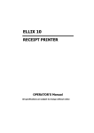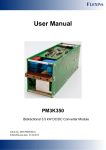
1
User Manual - preliminary -
Rev. 11.
11.09
LDPLDP-CW 2020-50
Before powering on your unit, read this manual thoroughly and make sure your
understood it fully.
Please pay attention to all safety warnings.
If you have any doubt or suggestion, please do not hesitate to contact us!
Schulz-Electronic GmbH
Dr.-Rudolf-Eberle-Straße 2
D-76534 Baden-Baden
Fon +49.7223.9636.30
Fax +49.7223. 9636.90
[email protected]
www.schulz-electronic.de
1
Table of Contents
LDP-CW 20-50 Data Sheet.......................................................................................................... 1
Table of Contents ....................................................................................................................... 3
Description of Connections......................................................................................................... 4
How to get started (quickstart without PLB-21)........................................................................... 6
How to get started with an PLB-21 ............................................................................................. 6
Dos and Don’ts ........................................................................................................................... 7
Absolute Maximum Ratings ........................................................................................................ 7
Functional Description ................................................................................................................ 8
Test Load .................................................................................................................................... 9
Power Supply.............................................................................................................................. 9
Cooling....................................................................................................................................... 9
Over Temperature Shutdown.................................................................................................... 10
Power on self test ..................................................................................................................... 11
Mechanical Dimensions ............................................................................................................ 10
Power on self test ..................................................................................................................... 11
Controlling the driver................................................................................................................ 11
Controlling the driver using a PLB-21 ........................................................................................ 12
Controlling the driver via PC ..................................................................................................... 15
Register description .................................................................................................................. 24
3
Description of Connections
The following drawing shows all connections that are available to the user.
4 Holes for
Heatsink
(3.1 mm trough)
VCC
GND
LD-Anode
GND
LDP-C-BOB-Connector (Pin 1 marked)
RS232 / PLB-Conn.(Pin 1 marked)
VCC
Supply voltage 12..48V, (56 V absolute maximum)
GND
Supply ground
LD+
Positive laser diode output (anode). Do not connect to ground! Use both
connectors parallel for high currents.
LD-
Negative laser diode output (cathode). Do not connect to ground! Use both
connectors parallel for high currents.
LDP-C BOB Conn
Mini-MOLEX Connector for analog/TTL-control of the driver (see below)
RS232/PLB21-Conn
Mini-MOLEX Connector for RS232 Communication or the PLB21 (see below)
For a more convenient use of the driver (e.g. in laboratory use) we recommend the optional available
product accessory LDP-C-BOB. Please see LDP-C-BOB manual for further details.
Pin-Assignments and Description of the MOLEX-pin header.
Pin Number
Description
Direction
Comments
1 (marked in red)
reserved
2
reserved
3
I-Soll
Input
Scale: 150 mV / A
4
Enable-Ext
Input
0 V = disabled, 3.3 V = driver enabled
5
Pulser-Ok
Output
0 V = laser diode driver not ok or power up self
test not passed yet; 3.3 V = driver ok / test
passed
6
GND
Output
7
reserved
8 (right)
GND
Output
Do not connect !
Pin Number
Description
Direction
Comments
1 (marked in red)
+12 V
Output
Only for the use with the PLB21, prevent any
overload or short! (max. 100 mA)
2
TXD
I/O
RS232-Standard serial interface
3
RXD
I/O
RS232-Standard serial interface
4 (right)
GND
Output
Do not connect !
Do not connect !
5
How to get started (quick-start without PLB-21)
What to do
Step #
Note
1
Unpack your Device.
2
Apply the supply voltage.
Apply any voltage between 12 V and 48
V at “VCC” with respect to GND. The
Voltage must be at least 5 V higher than
the expected compliance voltage of the
laser diode driver- Make sure there is no
voltage surge that could destroy the unit
when switching the power supply on!
3
Wait until “pulser-ok” is high
4
Apply the current setpoint
(scale: 150 mV / A)
Pin 5 with respect to Pin 6 must change
from 0 V to 3.3 V
For example: apply. 1.5 V to Pin 3 of the
BOB-connector with respect to GND (Pin
6) if you want to set current to 10 A
5
Set enable pin “high”.
6
Check
Apply 3.3 V to pin 4 of the BOB
connector. The current will ramp up now.
If the driver is not properly cooled, it will
shut down.
How to get started with an PLB-21
What to do
Step #
Note
1
Unpack your Device.
2
Connect the PLB-21
Use the PLB-21 pin header and the
special cable
3
Apply the supply voltage.
Apply any voltage between 12 V and
48 V to “VCC” with respect to GND.
The Voltage must be at least 5 V higher
than the expected compliance voltage of
the laser diode.
4
Wait until “pulser-ok” is high
5
Apply the current setpoint
Pin 5 with respect to Pin 6 must change
from 0 V to 3.3 V
Use the PLB-21 to switch from external to
internal setpoint, set the setpoint by
turning the dial
6
Set enable pin “high”.
7
Check
Apply 3.3 V to pin 4 of the BOB
connector. The current will ramp up now.
If the driver is not properly cooled, it will
shut down.
Dos and Don’ts
Never make a short at the output. This will not do any harm to the laser driver but will result in
an incorrect current measurement.
Keep the connection between power supply and driver as well as the connection between
driver and laser diode as short as possible.
Mount the driver on an appropriate heat sink. The driver will shut down under overtemperature circumstances. Depending on the desired current a slight airflow across the black
coils on top is necessary. Please keep the temperature of these devices below 85 °C
This diver uses a “high-side” current sensing technique. The GND of the VCC terminal is the
same as the GND of the LD terminal.
The driver is CW-operation only.
Absolute Maximum Ratings
Supply voltage range: +12 V .. +56 V (destroying limit)
Maximum input current: 20 A
Maximum laser diode output current: 20 A
Maximum laser diode compliance voltage: 50 V
BOB-connector input and output voltages: 0 V to 3.3 V (terminals are 5 V proof)
BOB-connector output currents: 1 mA
Auxiliary 3.3 V supply voltage output current: 30 mA (Pin 8 of BOB-Conn planned for Rev 2.1)
Auxiliary 12 V supply voltage output current: 100 mA (Pin1 of PLB-21 Conn)
Operating temperature: 0 - 55 °C
7
Functional Description
The LDP-CW operates with four parallel buck converters (S1, S2, D1, D2, L1; S3, S4, D3, D4, L2; S5,
S6, D5, D6, L3; S7, S8, D7, D8, L4). Every single converter has an independent control loop with a
current sensor (Imeas1, Imeas2, Imeas3 and Imeas4). The set point current that is defined by the user
is evenly spread over all four converters.
Several security features protect the laser diode and LDP-CW from damage. D8 protects the laser
diode from reverse currents while D7 protects the driver in case of a load failure. In case of a failure,
the control unit disables the LDP-CW. A soft-start mechanism slowly raises the current after enabling
the LDP-CW.
Operation Principle of LDP-CW 20 50 driver
Element
Function
S1, S2, S3, S4, S5, S6, S7, S8,
D1, D2, D3, D4, D5, D6, D7,
D8, L1, L2, L3, L4
Buck converter
C0
Input buffer capacitor
D7, D8
Laser diode and driver protection diodes
Test Load
A common method to test the driver is to connect a regular silicon rectifier diode to the driver
output. Here has to be paid attention to the junction capacitance of the diode. Only fast recovery
diodes (or similar) have a low parasitic capacitance as laser diodes have. To achieve reasonable test
results, the parasitic elements of the test diode and the connection must be very similar to a laser
diode approach. Regular silicon rectifier diodes have a junction capacitance of several microfarads
and are not a suitable test load! The use of these diodes will yield in incorrect current measurement
at the pulse edges!
Power Supply
The power supply must be able to cover the output power plus the internal power losses (please see next
chapter). Example: you have a 48 V power supply and a Jenoptik JOLD-75-FC-11 laser diode with up to 20 V
compliance voltage and a 12 A current (max. values). At 12 A the driver needs at least additional 12 W to
cover the internal losses. The total power consumption will be: 20 V x 12 A + 12 W = 252 W. Divided by 48 V
this yields 5.25 A (better 6 A) of current consumption at the DC-terminals.
Cooling
The driver produces up to 31 W of losses. Thus the base plate has to be mounted on a heat sink to
ensure proper operation and prevent an over temperature shutdown. If working with high currents
above 10 A it is recommended to cool the power inductors as well. This can be achieved easily by
placing the driver with its heat sink in the air flow of a fan.
35
Power dissipation vs. LD-current
30
Losses in W
25
20
15
10
5
0
1
2
3
4
5
6
7
8
9
10
11
12
13
Iout in A
Power dissipation over output current
9
14
15
16
17
18
19
20
Over Temperature Shutdown
To protect itself, the LDP-CW automatically shuts down itself if its temperature rises above 80°C. This
condition is latched and the appropriate bit in the ERROR register is set. To re- enable the LDP-CW the
ENABLE pin must be toggled (set low and then high)..
Mechanical Dimensions
Over all height: 30 mm
All dimensions in mm
Power on self test
Each time the driver is powered up, it performs a test of its internal safety features. The driver cannot
be enabled until a self test has been performed successfully. The PULSER_OK signal will be pulled high
when the test has been successful.
The test will take less than 5 seconds, but can take up to 15 seconds due to internal time-outs if any
failures are detected.
Controlling the driver
The driver can be operated stand alone, with a PLB-21 or a PC connected to it via USB. It remembers
all settings from the last time it was powered on, unless configured to load default values on poweron. In this case it loads pre-configured settings each time the power is applied. Connecting a digital
control to the driver does not alter the internal settings.
No digital control (factory default)
default)
If no digital control (PLB-21 or USB) is attached, only the BOB-Connector could be used to control the
driver. If configured so, the pin 10 at the BOB connector (“Isetpoint“) can be used to control the setpoint
current. To enable the output pin7 at the BOB connector (“ENABLE”) must be set HIGH. If an error
occurs (e.g. over temperature), the driver will be disabled and the pin 1 of the BOB connector
(“PULSER_OK”) is pulled low. The “enable” pin has to be toggled to enable the driver again.
When using the LDP-C series the ENABLE pin enables the driver but not the current output. Pin6 of
BOB connector (“PULSE”) directly controls the current output in that case. The PULSE input does not
trigger a soft start. Hence the configured setpoint current applies as fast as possible to the output.
PLBPLB-21
If a PLB-21 is attached to the driver, it can be used to control the behavior of the driver. The PLB-21
may ask for a driver to download. This must be confirmed with “yes” in order for the PLB-21 to work
properly. This must always be done when the PLB-21 was connected to any other PicoLAS product.
After the download all operating parameters can be accessed using the PLB-21. For a detailed
description see chapter PLB-21 below.
USB
If the driver is connected to a PC using an USB cable, all operating parameters can be accessed via a
serial RS232 terminal program or the PicoLAS protocol. The PLB-21 is automatically disabled if a USB
connection is established. For a detailed description of the serial text protocol and the PicoLAS
protocol see below.
PC
If the driver is connected to a PC, all operating parameters can be accessed via a serial RS232 terminal
program or the PicoLAS protocol. For a detailed description of the serial text protocol and the PicoLAS
protocol see below.
11
Controlling the driver using a PLB-21
To control the driver with a PLB-21 it must be connected via the enclosed cable. The PLB-21 will not
work if the USB and the PLB-21 are connected at the same time.
When the PLB-21 is connected the first time to the driver the user is asked to download a new driver.
This must be confirmed with “yes” for working the PLB-21 properly.
Menu Structure
The following diagram shows the structure of the PLB-21 menu which affects the driver. All entries are
described in detail. All other menu entries are described in the PLB-21 manual. For detailed
instructions see the PLB-21 manual.
Menu root
- Pulseparameter
o Width
o Reprate
o Cur(int/ext)
o Simmer
-
Trigger
o Mode
o Edge
-
Config
o
o
o
o
Occur(not in HW version 1.2)
Scut
Noload
SStart
-
Defaults
o Def. pwron
o Load defaults
o Save defaults
-
Temperature
o Dev. Off
o Temp 1
o Temp 2
o Temp 3
-
Measurement
o Uin
o Udiode
o IDiode
Pulseparameter
In this menu point can be modified the setpoint current and simmer current. See the device specific
datasheet for detailed information.
Width
This value defines the width of the pulses generated by the internal pulse generator if the internal
trigger is used. It is measured in steps of 0.1us.
Reprate
This value defines the repetition rate of the pulses generated by the internal pulse generator if the
internal trigger is used. It is measured in steps of 1 Hz.
Cur (int/ext)
This value defines the setpoint current. It can be switched between internal (int) and external (ext)
setpoint by pressing the F1 key.
When using the internal setpoint, the value can be modified by the user.
When using the external setpoint, the value shown is measured value supplied at Pin 10 of the BOB
connector. The display is updated every few seconds, so it is not accurate when using analogue
modulation.
Simmer
A Simmer current is not available with a LDP-C series when using trigger modes internal or external.
Trigger
The LDP-C supports various trigger modes. These are selected in this Submenu.
Trigger
Possible values are “internal”, “external” and “CW”. Please note that any change disables the output.
Edge
This value defines the speed of the rising edge. Possible ranges from 0 to 255. The smaller the value
is, the smaller is the rise time. It is not used in CW mode.
Config
The LDP-C has some additional safety features which can be user enabled. This is done within this
Submenu.
Occur (not in HW version 1.2)
Using the F1 key an additional over current protection can be enabled. If enabled, the LDP-C disables
automatically if the output current rises below the given maximum value. The display shows the actual
value and it can be modified using the jogdial. If disabled, the display will just read “disabled”.
Scut
If enabled, the LDP-C disables automatically if a shortcut on the output clamps during operation is
detected. Please note that this feature will not operate properly when the setpoint current is
modulated or a compliance voltage below 1 volt is used.
Noload
If enabled, the LDP-C disables automatically if the load has been disconnected during operation.
Please note that this feature will not operate properly if the setpoint current is modulated.
Start
The value shown here is the time span in which the LDP-C raises its output current to the given
setpoint when enabled.
Config
The driver can load a default setting each time it powers up or the user commands it to do so. This is
done within this Submenu.
Def. pwron
13
When enabled, the driver loads the saved settings each time it powers up.
Load
When activated via turning the Jogdial or the ENTER key all internal registers are changed to the
previously saved values. The output stage has to be re- enabled via the L_ON bit or the FIRE Key
afterwards
Save
When activated via turning the Jogdial or the ENTER key all internal registers are stored into an
internal EEprom for later usage.
Temperature
The LDP-C 120-20 is equipped with several temperature sensors. In this submenu, the actual and
shutdown temperatures can be read and modified. All values are in °C.
Dev. Off
This shows the user defined shutdown temperature. If the LDP-C 120-20 reaches this temperature
during operation, the output will be disabled and an error message is displayed. It can be modified
within 40….80 °C.
Temp 1…
1 …3
This shows the actual temperatures measured by the sensors of the LDP-C 120-20.
Measurement
This submenu holds some runtime measurement information.
Uin
This shows the measured value of the supply voltage.
Udiode
This shows the measured value of the compliance voltage of the connected load. The output must be
enabled for a correct result. Please note that this is not a real-time measurement. If the Setpoint is
modulated, the display may show incorrect values. In that case use the signal of the analogue current
monitor at pin 9 on the BOB connector with appropriate measurement equipment.
Idiode
This shows the measured value of the current flow through the connected load.
If an Error Occurs
If an error occurs during operation the pulse output is switched off, the “pulser_ok_ext” signal on the
BOB connector is pulled low and a message is displayed on the PLB-21. If no other action is described
on the display, a toggle of the ENABLE pin resets the error condition and re- enables the driver.
Controlling the driver via a PC
Introduction
When the LDP-CW is connected to a PC, it allows communications over a serial text interface as well
as the PicoLAS protocol. While the text interface is designed for communication with a terminal
program, the PicoLAS protocol is designed as a system interact protocol.
The switching between the two protocols occurs automatically as soon as the driver receives a certain
sequence. The corresponding commands are:
•
PING for the PicoLAS protocol
•
“init
init”
init followed by <Enter> for the text interface
Description of the RS232 Interface
The LDP-CW 20-50 implements a standard RS232 interface. It can be connected to a PC using a
three-wire connection. The connection settings are:
Baud rate
115200
Data bits
8
Stop bits
1
Parity
even
15
The Serial Text Interface
The following section describes the structure and commands of the text interface.
Structure
Every command that is sent to the LDP-CW must be completed with a CR (Enter). It consists of a
command word followed by one or more parameters. If the command was successfully executed a
“00” is sent, otherwise a “01”. If there is an error pending, the response will be “10”, otherwise
“11”. If the command requires an answer parameter, this parameter is sent before the confirmation is
given.
Example:
The user would like to read out the actual setpoint current:
User input:
gcur<Enter>
Output of the LDP-CW: 12.25<CR><LF>
00<CR><LF>
Example 2:
The user would like to set a new setpoint current:
User input:
scur 25.7<Enter>
Output of the LDP-CW: 25.7<CR><LF>
00<CR><LF>
Input is done in ASCII code and is case sensitive. Every terminal can be used which supports this
standard.
Commands for the LDPLDP-CW
The following table contains a command reference for the LDP-CW.
Command
Parameter
Answer
Description
scur
Current in A
--
Sets the pulse current to the indicated value. A
dot is used as decimal point. No more then
two decimal places are used! (12.225 is the
same as 12.22)
gcur
--
Current in A
Outputs the present output current
gcurmin
--
Current in A
Outputs the minimum output current
gcurmax
--
Current in A
Outputs the maximum output current
on
--
--
Activates the output
off
--
--
Deactivates the output
curext
--
--
use external current setpoint
curint
--
--
use internal current setpoint
Command
Parameter
Answer
Description
gerr
--
32 bit number
Outputs the ERROR register
gerrtxt
--
error text
description of every pending error
slstat
32 bit number
--
Sets the LSTAT register to the value
glstat
--
32 bit number
Outputs the LSTAT register
gserial
--
serial number
Returns the device serial number
gname
--
device name
Returns the devices internal name
ghwver
--
hardware version
prints out the hardware version
gswver
--
software version
prints out the software version
ps
--
current settings
Prints out an overview of all settings
loaddefault
--
--
loads previously saved settings
savedefault
--
--
saves the current settings as defaults
sp
32 bit number
--
Sets the parameter of the P-controller
gp
--
P value
returns the parameter of the P-controller
gpmin
--
minimum P value
returns the minimum parameter of the Pcontroller
gpmax
--
maximum P value
returns the maximum parameter of the Pcontroller
si
32 bit number
--
Sets the parameter of the I-controller
gi
--
I value
returns the parameter of the I-controller
gimin
--
minimum I value
returns the minimum parameter of the Icontroller
gimax
--
maximum I value
returns the maximum parameter of the Icontroller
sd
32 bit number
--
Sets the parameter of the D-controller
gd
--
D value
returns the parameter of the D-controller
gdmin
--
minimum D value
returns the minimum parameter of the Dcontroller
gdmax
--
maximum D value
returns the maximum parameter of the Dcontroller
If an Error Occurs
If an error occurs during operation the pulse output is switched off and the return value of a
command is no longer “00” or “01” but “10” or “11”. Errors have to be acknowledged with a
toggle of the ENABLE signal, otherwise switching on again of LDP-CW output is not possible. For
more details see the description of the ERROR register.
To retrieve the error, use the gerr command for the content of the ERROR register or the gerrtxt
command for a human readable form.
17
The PicoLAS Protocol
The following section describes the structure and possible commands of the PicoLAS protocol.
Structure
Each transmission consists of 12 bytes – called a frame as follows – which must be sent consecutively.
Otherwise the system times out and the transmission must start again from the beginning.
A frame has a fixed structure. The first two bytes describe the command, the following eight bytes the
parameters, followed by one reserved byte and one checksum byte. The checksum is calculated out of
the first 11 bytes which are linked by a bitwise XOR.
Thus a frame has the following structure:
Byte
Meaning
1
Bit 8-15 of the command
2
Bit 0-7 of the command
3
Bit 56-63 of the parameter
4
Bit 48-55 of the parameter
5
Bit 40-47 of the parameter
6
Bit 32-39 of the parameter
7
Bit 24-31 of the parameter
8
Bit 16-23 of the parameter
9
Bit 8-15 of the parameter
10
Bit 0-7 of the parameter
11
Reserved, always 0x00
12
Checksum
A properly received frame must be acknowledged by the recipient with an answer, which is also a
frame. If the acknowledgement does not occur then the command has not been processed and the
sending procedure should be repeated.
If the recipient recognizes the command as valid, but not the parameters, then it will answer with a
ILGLPARAM (0xFF12) as command.
In the case that the recipient receives an invalid command it will answer with UNCOM (0xFF13).
If a faulty checksum is recognized then the answer is RXERROR (0xFF10). If this error occurs often then
the connection should be checked.
Using the REPEAT (0xFF11) command the recipient can instruct the sender to send the most recent
frame again.
General
General Commands
The following list contains an overview of the general commands which are supported by every
product from PicoLAS which makes use of this protocol. The explanation of the individual commands
is given further below.
Command Name
Sent Frame
Answer
Answer Frame
Command
Parameter
Command
Parameter
PING
0xFE01
0
0xFF01
0
IDENT
0xFE02
0
0xFF02
ID
GETHARDVER
0xFE06
0
0xFF06
Version
GETSOFTVER
0xFE07
0
0xFF07
Version
GETSERIAL
0xFE08
0 … 20
0xFF08
Refer to description
GETIDSTRING
0xFE09
0 … 20
0xFF09
Refer to description
PING
This command is used to determine the presence of a connected driver and to initialize its interface. It
does not change any registers. The command parameter is always 0, the answer parameter too.
IDENT
This command is used to determine the device ID of an attached recipient. It has no effect on the
condition of the recipient. The parameter is always 0. The answer contains the ID.
GETHARDVER
Instructs the driver to send back the version number of its hardware. The parameter is always 0. The
answer contains the hardware version number. The format of the answer is:
0x000000<major><minor><revision>. In other words, one byte for each of the three elements of the
version number.
As example, version 1.2.3 has the parameter 0x000000010203.
GETSOFTVER
Instructs the driver to send back the version number of its firmware. The parameter is always 0.
The answer contains the software version of the recipient. The format of the answer is:
0x000000<major><minor><revision>. In other words, one byte for each of the three elements of the
version number.
As example, version 2.3.4 has the parameter 0x000000020304.
GETSERIAL
Instructs the driver to send back its serial number. If 0 is sent as parameter, the answer contains the
number of (ASCII) digits of the serial number; otherwise the respective position of the serial number is
sent in ASCII format.
GETIDSTRING
Instructs the driver to send back its name. If 0 is sent as parameter, the answer contains the number
of digits of the string, otherwise the respective position of the serial number is sent in ASCII format.
19
Commands for the driver
The following table contains a list of the commands which the LDP-CW supports in addition to the
generally applicable commands. An explanation of the individual commands and its parameters
follows afterwards.
Command
Sent Frame
Received Frame
Command Parameter
Command Parameter
GETSOLL
0x0010
0
0x0101
32 bit value
GETSOLLMIN
0x0011
0
0x0101
32 bit value
GETSOLLMAX
0x0012
0
0x0101
32 bit value
SETSOLL
0x0013
Refer to description
0x0101
32 bit value
GETSOLLEXT
0x0014
0
0x0101
32 bit value
GETLSTAT
0x0020
0
0x0103
32 bit value
GETERROR
0x0021
0
0x0114
32 bit value
GETREGS
0x0022
0
0x0105
64 bit value
SETLSTAT
0x0023
Refer to description
0x0103
32 bit value
CLEARERROR
0x0024
0
0x0104
0
SAVEDEFAULTS
0x0027
0
0x0112
0
LOADDEFAULTS
0x0028
0
0x0112
0
GETKPMIN
0x0040
0
0x010A
32 bit value
GETKPMAX
0x0041
0
0x010A
32 bit value
GETKP
0x0042
0
0x010A
32 bit value
SETKP
0x0043
Refer to description
0x010A
32 bit value
GETKIMIN
0x0044
0
0x010B
32 bit value
GETKIMAX
0x0045
0
0x010B
32 bit value
GETKI
0x0046
0
0x010B
32 bit value
SETKI
0x0047
Refer to description
0x010B
32 bit value
GETKDMIN
0x0048
0
0x010C
32 bit value
GETKDMAX
0x0049
0
0x010C
32 bit value
GETKD
0x004A
0
0x010C
32 bit value
SETKD
0x004B
Refer to description
0x010C
32 bit value
Description of the Individual Commands
GETSOLL
GETSOLL
The return value contains the actual setpoint value in steps of 0.01A.
GETSOLLMIN
GETSOLLMIN
The return value contains the minimum setpoint value in steps of 0.01A.
GETSOLLMAX
GETSOLLMAX
The return value contains the maximum setpoint value in steps of 0.01A.
SETSOLL
This command sets the current setpoint to the given value in steps of 0.01A. The value must be within
the borders defined by the minimum and maximum current values given by the GETSOLLMIN and
GETSOLLMAX command.
The return value contains the actual setpoint value.
GETSOLLEXT
GETSOLLEXT
The return value contains the measured and converted value of the external analogue setpoint in
steps of 0.01A.
GETLSTAT
This command returns the value of the LSTAT register. For a complete description of this register see
below.
GETERROR
This command returns the value of the ERROR register. For a complete description of this register see
below.
GETREGS
This command returns the value of the LSTAT and ERROR register combined in a single 64bit value.
The lower 32bit represents the LSTAT register, the upper 32bit the ERROR register.
SETLSTAT
This command sets the LSTAT register to the given value. The return value contains the new register
value.
CLEARERROR
This command clears a part of the internal ERROR register. For a detailed description of the ERROR
register see below.
SAVEDEFAULTS
This command saves all settings to an internal EEProm.
LOADDEFAULTS
LOADDEFAULTS
This command loads previously saved settings into the driver.
21
GETKPMIN
The return value contains the minimum value of the P-controller.
GETKPMAX
The return value contains the maximum value of the P-controller.
GETKP
The return value contains the maximum value of the P-controller.
SETKP
This command sets the value of the P-controller to the given value. The value must be within the
borders defined by the minimum and maximum current values given by the GETKPMIN and
GETKPMAX command.
The return value contains the actual value.
GETKIMIN
The return value contains the minimum value of the I-controller.
GETKIMAX
The return value contains the maximum value of the I-controller.
GETKI
The return value contains the maximum value of the I-controller.
SETKI
This command sets the value of the I-controller to the given value. The value must be within the
borders defined by the minimum and maximum current values given by the GETKIMIN and GETKIMAX
command.
The return value contains the actual value.
GETKDMIN
GETKDMIN
The return value contains the minimum value of the D-controller.
GETKDMAX
The return value contains the maximum value of the D-controller.
GETKD
The return value contains the maximum value of the D-controller.
SETKD
This command sets the value of the D-controller to the given value. The value must be within the
borders defined by the minimum and maximum current values given by the GETKDMIN and
GETKDMAX command.
The return value contains the actual value.
Register description
Description of the LSTAT
LSTAT Register
The following list contains a description of the individual LSTAT bits. These can be read with
GETLSTAT and written with SETLSTAT. With SETLSTAT a complete 32 bit word must always be
written. Thus, to change individual bits, first the register must be read out with GETLSTAT, then the
desired bits changed and then with SETLSTAT passed again to the LDP-CW.
Bit
Name
Read/Write
Meaning
0
L_ON
Read/write
Switch on/off the pulse output. Note: that this
bit is automatically set high every time the
driver is powered on.
1
ISOLL_EXT
Read/Write
When “1” the external setpoint current is used
2
PULSER_OK
Read
Indicates that the driver is in no error condition
3
ENABLE_OK
Read
Indicates that the external enable is given
4
DEFAULT_ON_PWRON
Read/Write
When “1” the driver will load the default
values at each power-up.
5-31
Reserved
Read
Reserved
Description of the ERROR Register
The following list contains a description of the individual bits of the ERROR register. A “1” as a bit
leads to a deactivation of the drivers output.
The Bits 0 and 1 are cleared every time the ENABLE pin is set low or when the CLEAERROR command
is used.
The Bits 6 and 7 are set during the power on self test. They can not be cleared by the ENABLE pin or
the CLEARERROR command. If one of these bits is set, the supply voltage should be switch off and on
again. If the error persists, the LDP-CW needs to be repaired.
Bit
Name
R/W
Meaning
0
DRV_OVERTEMP
Read
Indicates an over temperature shutdown of the output
stage.
1
DRV_FAIL
Read
Indicates a shutdown of the LDP-CW due to a load failure
or an over current
2
reserved
Read
Reserved
3
reserved
Read
Reserved
4
CFG_CHKSUM_FAIL
Read
Indicates that the internal configuration register is corrupt.
If this error persists, the LDP-CW needs to be repaired.
5
reserved
Read
Reserved
6
CAL_CHKSUM_FAIL
Read
Indicates that the internal calibration registers are corrupt.
If this error persists, the LDP-CW needs to be repaired.
7
DEF_CHKSUM_FAIL
Read
Indicates that the internal default registers are corrupt. The
default values should be re- saved.
8
reserved
Read
Reserved
931
Reserved
Read
Reserved
23