1
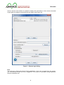
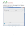
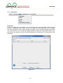
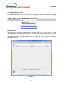
Project no.: 257398
Co-funded by the
European Union
Project title: Advanced
predictive-analysis-based
decision-support engine for logistics
Start date of project: 01.10.2010
End date of project: 30.09.2013
Duration: 36 months
7th FP topic addressed:
Challenge 4: Digital libraries and content: ICT-2009.4.3: Intelligent Information Management
Objective
Small or medium scale focused research project (STREP)
D5.3 User manual
Deliverable
TABLE OF CONTENTS
Table of contents ................................................................................................................... 2
1. Executive summary ........................................................................................................ 3
2. Download ....................................................................................................................... 4
2.1. Required software ................................................................................................... 4
3. Installation ...................................................................................................................... 4
4. Control Center ................................................................................................................ 5
4.1. Main menu .............................................................................................................. 6
4.1.1. Engine menu .................................................................................................... 6
4.1.2. Keystores menu ..............................................................................................10
4.1.3. Flow menu ......................................................................................................16
4.1.4. Administration menu .......................................................................................22
4.1.5. Data sources menu .........................................................................................29
4.2. Manage engine configuration window ....................................................................44
4.3. Getting started........................................................................................................49
5. Flow Modeller ................................................................................................................50
5.1. Overview of the user interface ................................................................................50
5.2. Using the navigator window....................................................................................52
5.3. Create a new flow description ................................................................................53
5.4. Add a block from template ......................................................................................53
5.5. Moving blocks ........................................................................................................53
5.6. Create a composite block .......................................................................................54
5.6.1. Navigating using the breadcrumb view ............................................................55
5.6.2. Create input and output ports for a composite block ........................................55
5.7. Create constant inputs ...........................................................................................56
5.8. Create connections ................................................................................................56
5.9. Delete blocks..........................................................................................................57
5.10.
Save the flow description ....................................................................................57
5.11.
Open a flow description ......................................................................................58
6. Advance Elicitation Tool ................................................................................................59
6.1. Accessing the “Advance Elicitation Tool” ................................................................59
6.2. File-lists page .........................................................................................................60
6.3. Download file..........................................................................................................60
6.4. Edit file ...................................................................................................................60
6.5. Edit file page ..........................................................................................................61
6.6. Upload File .............................................................................................................63
6.7. Delete a file ............................................................................................................63
6.8. View File ................................................................................................................64
2
Deliverable
1. EXECUTIVE SUMMARY
This document provides the user documentation for the ADVANCE Control Centre, Flow
Editor and Elicitation Tool.
The ADVANCE Control Centre is included in the Engine binary distribution and it is used to
perform administrative tasks and to deploy, execute and debug flows.
The ADVANCE Flow Editor is a visual flow diagram editor able to deal with the flow diagram
format described in D3.3 “Machine tractable flow descriptor format” and with the data
structures used by the ADVANCE Flow Engine as described in D5.2 “Software Solution
and test Results”. The document provides a guide for the user of the flow modeller interface
to complete common tasks required to create and edit flow diagrams. The guide is not aimed
at a specific user type as the examples are generic and do not deepen into the meaning of
what implies creating a block and connections from the ADVANCE Flow Engine point of
view.
The ADVANCE Elicitation Tool is a web based application that allows to edit and share the
elicitation tree data in the Galatea model as described in D6.4 “Algorithms to extract
expert cognitive models, decision driver factors and decision classes”.
3
Deliverable
2. DOWNLOAD
The Flow Engine can be downloaded from the project website at the following address:
http://sourceforge.net/projects/advance-project/
You can select to download the latest and most complete version from the main links showed
in the page, or select a specific version by clicking on “Browse All Files” and look through the
list of archived versions. There is a folder named “Flow Engine” where you can find all the
releases sorted by version number and date.
The name of the file to download is in the format “advance-full-[major].[minor].[micro].zip”,
where “advance-full” means that the archive contains the complete distribution of the Flow
Engine, including the Flow Editor, too.
2.1. Required software
The Flow Engine is a Java program, so you need the Java Runtime Environment installed on
your PC in order to use the software. You can download it from http://www.java.com and
click on the “Free Java Download” button. The Java software supports Windows, Mac OS X,
Linux and Solaris. Mac OS X version supports only the 64 bit, while for the other operating
system is available both the 32 bit and the 64 bit release. The web page automatically select
the right version for you, based on the Browser information, so you will only need
3. INSTALLATION
If Java Software is not already installed on the PC, install the Java Runtime Environment
according to the instructions included with the installer package you have downloaded in “2.1
Required software”.
Unpack the binary distribution into a convenient location so that the distribution resides in its
own directory (conventionally named "advance-full-[version]"). For the purposes of the
remainder of this document, the symbolic name "$ADV_ENGINE_HOME" is used to refer to
the full pathname of the release directory, that is the directory where Flow Engine has been
installed.
4
Deliverable
4. CONTROL CENTER
Double clicking on the Advance Flow Engine Control Center JAR will open the application
main window shown in Figure 1. You can execute your task using the menu items detailed
later in this chapter. You can use the “Engine” menu to run or connect to a Flow Engine, the
“Keystores” menu to manage your secure key files, the “Flow” menu to manage the flow
descriptors, the “Administrator” to perform administrative tasks, the “Data sources” menu to
manage local and remote data sources.
Figure 1 - Advance Flow Engine Control Center main window
5
Deliverable
4.1. Main menu
4.1.1. Engine menu
New
Selecting the New menu item will prompt for a working directory (i.e. the root directory of the
Flow Engine). Once the working directory has been selected, the “Manage engine
configuration” window will be opened to allow the user to edit the configuration (see section
4.2). The engine settings will be saved in the “flow_engine_config.xml” file under the “conf”
subdirectory inside the working directory.
Open
The Open menu item will ask the file name of the Flow Engine XML configuration file to load
and then prompt for a working directory (i.e. the root directory of the Flow Engine). Once this
selection has been done, the “Manage engine configuration” window will be opened (see
section 4.2) with the values loaded from the selected file. The user is then able to modify the
configuration and save it. The engine settings will be saved in the same file opened at the
beginning.
Run in-process
You can use this menu item to run an instance of the Flow Engine in the same process of the
Control Center. The user is asked to select a valid the engine configuration file (created for
example using the New menu) and a working directory. Please note that the working
directory must contain the block-registry.xml file. Running an instance of the Flow Engine
does not automatically log in the user. To perform any action on the engine, you still need to
login using the “login remote” menu item and entering “localhost” or “127.0.0.1” as the engine
address.
Login embedded
The “login embedded” menu item allows to log into an embedded instance of the flow engine.
The engine runs in the same process as the Control Center, similarly to the “Run in-process”
action, but the user is also logged into the engine. As show in Figure 2, selecting this menu
item will open a “Local login” dialog containing a list of recent login credentials used and the
date and time of the last login. Using the “New” and “Delete” button you can customize this
list. After a successfully login an entry is automatically added containing the credential used
to access the engine. When an item is selected from the list, the corresponding information is
filled in the bottom part of the dialog. This information included the “Path”, that is the location
of the flow engine XML configuration file, the “Working directory” and the user name. Logging
into an embedded engine does not require any password.
6
Deliverable
When the user is successfully logged in the flow engine, the main window is updated to
display the information on the current connected engine path, the engine version and the
user name (see Figure 44).
Figure 2 - Local login dialog
Login remote
Remote login is the right way to connect to a deployed flow engine, but it is not limited to
connecting to production servers. This menu item can be used to log into any running
instance of the flow engine, on the same PC or on any server, provided you enter the right
address to reach it. Selecting the menu item opens the “Remote login” dialog shown in
Figure 3. The dialog presents a list of recently used credentials, and you can add a new one
or delete an existing one. If you select and item from the list, the information is filled in the
bottom part of the dialog, where you can enter the actual login data used to connect to the
remote engine. If you don’t select any entry from the top list, or it is the first time you connect
to a remote engine, you must fill the data required by the form. In the address filed you must
specify the URL of the engine, for example “https://127.0.0.1/” if the engine runs on the same
machine (the symbolical “localhost” name can also be used). In the “Server verification
keystore” field you can select a key store where the key associated to the server is stored
(see “Manage engine keystores” for more information). Alternatively you can directly select
the server certificate in the corresponding named field: to do so, you can use the “Browse”
button that opens a standard file open dialog to select a “.cer” file anywhere on the file
system of your PC. The bottom part of the dialog is reserved to the authentication method
selection (password or certificate) and to input the corresponding information: for password
authentication methods, you must enter your user name and password; for certicate
authentication mode you must first select a key store from the list (see “Manage local
keystores” menu item, or use the “Manage keystore” button on the right of the combo box to
add a new key store if you don’t have any already defined). After selecting a valid key store,
you must specify the key alias (i.e. how the key is named inside the key store) and the key
password. Finally, you can click on the “Login” button to connect to the flow engine. If the
process is successful, the credentials used are saved to the list of recently used addresses,
or the information of the last login is update in case the credentials were already present in
7
Deliverable
the list, and the main window is updated to display the information on the current connected
engine path, the engine version and the user name (see Figure 44).
Figure 3 - Remote login dialog
Exit
The exit menu closes the Control Center application. If the user is logged into any engine,
this automatically means the user is logged off. If the case of in-process running instances,
they are closed as well.
8
Deliverable
4.1.2. Keystores menu
Manage local keystores
This dialog is used to manage local key stores. On the top you have a table listing the key
store name, location (i.e. the path to the file), date of creation and date of last modification.
You can use the filter field to limit the visualization only to the entries that match the filter text.
At the bottom of the table there the records count (i.e. the number of entries).
On the bottom of the dialog you can find a list of buttons to refresh the entire table, to create
a new key store (for further details see Figure 5 and the following paragraph), delete an entry
from the table (this only removes it from the records list, but does’t delete the file).
Figure 4 - Manage local keystores dialog
9
Deliverable
The “Create” button will open the “Keystore details” dialog show in Figure 5. You must load a
keystore in the Java KeyStore file format. You can use the “keytool” program, included in the
Java Software Development Kit, to create a new key store in this format – please refer to the
official documentation for more information (it can be accessed online at
http://docs.oracle.com/javase/6/docs/technotes/tools/solaris/keytool.html). Once a valid key
store is selected and loaded, the dialog will present its information as show in Figure 6.
Figure 5 – Empty Keystore details dialog for local keystores
10
Deliverable
If there is a key store loaded, the dialog will show some additional controls at the top and just
below the records count under the table. The controls on the top are a combo box that lists
all the available key stores and allows to directly go to a different one, without closing the
dialog, and four button to navigate the list of key stores forwards and backwards. Below this
controls there is a label that show the date of creation and the date of the last modification.
Under the table there is a “Generate” button to create e new key (see Figure 7 and the
following paragraph), a button menu to import and export the certificate or the private key, a
delete button to remove the selected key from the key store. At the very bottom of the dialog
there are buttons to refresh the entire table, to save the modified key store, to save and close
the dialog and to close the dialog discharging any modification.
Figure 6 - Keystore details dialog showing keys
11
Deliverable
The “generate key” dialog allows the user to create a new RSA or DSA key. In the top part of
the dialog you must enter some information for the key: a name to identify the key, the
algorithm to use (it can be either RSA or DSA, but the DSA key is generally preferred
because it is more secure), the password to protect the key, the password confirmation (i.e.
you must enter the password again to confirm it), and the domain parameters.
The bottom part of the dialog show the certificate attributes, requiring to fill in the certificate
issuer/owner’s common name (CN), the name of the organizational unit to which the
certificate issuer/owner belongs (ON), the organization to which the certificate issuer/owner
belongs (O), the certificate issuer/owner’s locality (T), the certificate issuer/owner’s state of
residence (ST), the certificate issuer/owner’s country of residence (C). The issuer field
identifies the entity that has signed and issued the certificate. The subject field identifies the
entity associated with the public key stored in the subject public key field.
Figure 7 - Generate key dialog
Manage engine keystores
This dialog shows the engine key stores, usually located in the engine configuration directory
(i.e. a directory named “conf” under the engine working directory). This dialog is only
available if the user is logged into the engine. The top of the dialog displays the full filename
and path of the engine configuration file and the engine version. Right below there is a filter
field, to limit the entries shown in the table to only the ones that match the filter. The major
space of the dialog is occupied by the table that shows the list of key stores. For each key
store it is displayed its name, its location (relative to the engine working directory), the date of
12
Deliverable
creation and the date of last modification. Right under the table there is a text label with the
information of the records count. At the bottom of the dialog there are the usual buttons to
refresh the entire content of the table, to create a new key store (see Figure 9), to delete an
entry from the table and to close the dialog.
Figure 8 - Manage engine keystores dialog
13
Deliverable
To create a new engine key store click on the “Create” button: the “Keystore details” dialog
shown in the following figure is opened. This dialog, being associated with a running instance
of the engine, show at the top the usual information about the engine configuration file and
version. At the top you can enter the name, password and location of the key store. Just
above the table there is the filter field to limit the displayed entries to the ones that match the
filter text. The table shows the list of keys contained in the store, and for each of them it
reports the type (RSA or DSA), name and date of creation.
Figure 9 - Keystore details dialog for engine keystores
14
Deliverable
4.1.3. Flow menu
Download
If you are logged into an engine, you can download any flow description that has been
present or uploaded inside a realm. When you select the “download” menu entry, a dialog
will open that shows a list of realms currently available in the connected engine (see Figure
10). From that list you can select the desired realm and press the “Download” button: a file
chooser will be opened to select the desired destination for the XML file containing the flow
description.
Figure 10
15
Deliverable
Upload
You can upload flow descriptions to the engine using the “upload” menu item. You can select
the destination realm in the dialog that will open (see Figure 11): select the desired realm in
the list and the press the “upload” button. A file chooser dialog will be presented to you to
browse and select the source flow description XML file.
Figure 11
16
Deliverable
Verify
The “verify” menu item is used to validate the flow description present in the realm. The
verification result will be displayed in a message box (see Figure 12).
Figure 12
If the verification is successful, the compilation results will be shown in a separate window,
as show in Figure 13.
Figure 13
17
Deliverable
Debug
Using this menu item yaou have access to the blocks and ports debug window shown in
Figure 14. From this window you can add watches to look in the values that are update in the
table that fill the main part of the window. For each watched value the table show the realm it
lives in, the block it belongs to, the port name, the time stamp of the last update and the last
value. To add a new watch you must use the upper part of the window first selecting the
realm from the list presented by the combo box; after the realm has been selected the block
list is retrieved and presented in the second combo box. You can select a block and then you
can either watch the block, pressing the “watch” button on the side of the block name, or
watch a port, using the third combo box filled with the port names, pressing the “watch”
button on the side of the port name.
Figure 14
18
Deliverable
Last compilation result
This menu item gives you access to the last compilation results. You can select the desired
realm from the window that will open and then press the “view” button to see the compilation
results and/or errors (see Figure 15).
Figure 15
19
Deliverable
If the compilation was successfully the compilation results show the list of wires and their
type (see for example Figure 16).
Figure 16
20
Deliverable
4.1.4. Administration menu
In the administration menu you can find items to manage the engine including listing, adding
and removing realms, users and groups, listing blocks and shutting down the engine.
Manage realms
This menu item opens the “manage realms” window where you can see a list of all the
realms present in the engine (see Figure 17). You can create a new realm using the “create”
button and entering the realm name when requested. When you select a realm from the list,
it is possible to do the following actions as shown in Figure 18: stat, stop, upload, download,
compilation results.
Figure 17
21
Deliverable
The start and stop actions are used to control the execution of the flow description present in
the selected realms. The upload, download and compilation results actions are equivalent to
the corresponding menu item in the “flow” menu.
Figure 18
Manage users
Use this menu item to open a window where you can manage the users allowed to access
the engine (see Figure 19). You can select a user from the list and remove it using the
“delete” button or you can create a new user using the “create” button.
Figure 19
22
Deliverable
To create a new user, a dialog is presented that must be filled with the required data. There
are three sections to complete in order to finish the procedure. The first section is about
general user information (see Figure 20): here you can enable or disable the account, enter
the name of the user, email address, pager number, mobile number for SMS messages,
preferred date and time format, preferred number format with thousand and decimal
separator, login method (password or certificate).
Figure 20
23
Deliverable
The second section is about user’s rights (see Figure 21), i.e. the action he/she is allowed to
execute from the administrative interface. For each of the available right it is possible to
pacify if the user is granted or not by selection the corresponding check box in the list.
Figure 21
24
Deliverable
The last section is where you can specify the list of realms that the user is allowed to access:
foe arch realm you can explicitly allow listing, starting, stopping, reading (i.e. downloading),
writing (i.e. uploading), debugging (i.e. watching blocks and/or variables).
The new user is created when you press the “save” or “save & close” buttons. The
credentials and access rights are stored in the configuration file of the currently connected
engine, they are not stored locally in the Control Centre.
25
Deliverable
Manage notification groups
You can create a list of users and manage it as a group using the “manage notification
groups” menu item. In the dialog window (see Figure 22) you have a list of groups on the left,
where you can add and remove entries using the buttons below the list box. When you select
a group, on the right it is displayed the list of contacts belonging to that group. You can add
or remove entries from the contact list using the buttons below the list box on the right. There
are three types of groups that can be selected from the combo box in the upper part of the
dialog window: email, pager, SMS. The data is saved when you press the “save” or “save &
close” button and the configuration is stored in the currently connected engine, it is not stored
locally in the Control Centre.
Figure 22
26
Deliverable
List blocks
The “list blocks” menu item opens a dialog window that shows all the blocks available in the
currently connected engine (see Figure 23). For each block it is displayed its name, category,
keyword and documentation. Additionally, by selecting an entry in the list, the XML definition
of the block is shown in the lower part of the dialog window, providing the full description of
input and output parameters (name and type).
Figure 23
Shutdown
The “shutdown” menu item can be used to log off from the connected engine and shut it
down. A dialog will ask the user to confirm the action before proceeding (see Figure 24).
Figure 24
27
Deliverable
4.1.5. Data sources menu
The data sources available in the engine can be defined using the “data sources” menu:
there are several items available, one for each data source type. The data source
configuration is stored on the engine so in order to enable the menu you must be connected
and successfully logged on to an engine.
28
Deliverable
JDBC
This data source can connect to databases using the Java Database Connectivity API
(JDBC). This allows to access databases from different vendors provided that there is a
corresponding driver available in the system. The data sources currently available in the
engine are listed in the dialog window as shown in Figure 25.
Figure 25
29
Deliverable
To register a new data source you can use the “create” button and fill the data in the dialog
window show in Figure 26.
• Name: the name of the data store used to reference it from the blocks. This should be
an unique name to identify and access the data store.
• Driver: here you can choose from a predefined list of common types of driver (Oracle,
MS SQL, MySQL) of choose the generic type otherwise.
• URL: enter the JDBC address used to connect to the driver. If you choose a driver
type in the combo box, this filed is filled with a template URL and you only need to
replace the required information (host name, port number, database name).
• User: the name of the user account in the database system.
• Password: the password associated to the user.
• Connection pool size: the number of concurrent connections that are kept open to
optimize the connection to the database.
Figure 26
30
Deliverable
SOAP
The Simple Object Access Protocol (SOAP) facilitates interoperability among a wide range of
programs and platforms, making existing applications accessible to a broader range of users.
SOAP combines the proven Web technology of HTTP with the flexibility and extensibility of
XML. With a SOAP data source the engine can connect with an external or legacy system.
The dialog window show in Figure 27 lists all the SOAP data sources configured in the
engine and you can add new ones by pressing the “create” button.
Figure 27
31
Deliverable
To create a new SOAP data source you need to enter the data show in Figure 28 and
described below:
• Name: the name of the data store used to reference it from the blocks. This should be
a unique name to identify and access the data store.
• Endpoint: a URL that identifies the location on the HTTP service where the Web
services listener is listening for incoming requests.
• Target object URI: the resource address of the service you want to use.
• Namespace URI: the namespace that qualify the XML elements in the message.
• Method name: the name of the target object’s method that should be called.
• Encrypted channel: here you can specify if the communication is encrypted. If
enabled you must also select the keystore, alias and password to use.
Figure 28
32
Deliverable
JMS
The Java Message Service (JMS) is a Java API that allows applications to create, send,
receive, and read messages. With a JMS data source the engine can connect with an
external system written in Java. The dialog window show in Figure 29 lists all the JMS data
sources configured in the engine and you can add new ones by pressing the “create” button.
Figure 29
33
Deliverable
To register a new data source you must fill the data in the dialog window show in Figure 30
and detailed below:
• Name: the name of the data store used to reference it from the blocks. This should be
a unique name to identify and access the data store.
• Driver: here you can choose from a predefined list of most used types of driver
(OpenJMS, IBM WebSphere MQ, Apache ActiveMQ) of choose the generic type
otherwise.
• URL: enter the JMS address used to connect to the driver. If you choose a driver type
in the combo box, this filed is filled with a template URL and you only need to replace
the required information (host name and port number).
• User: the name of the user account in the system.
• Password: the password associated to the user.
• Queue manager: the name of the queue manager.
• Queue: the name of the queue.
• Connection pool size: the number of concurrent connections that are kept open to
optimize the connection to the messaging service.
Figure 30
34
Deliverable
Web
The Hypertext Transfer Protocol (HTTP) is designed to enable communications between
clients and servers. HTTP works as a request-response protocol between a client and
server. The engine submits an HTTP request to the server and the server returns a response
that is made available as a data source. The dialog window show in Figure 31 lists all the
Web data sources configured in the engine and you can add new ones by pressing the
“create” button.
Figure 31
35
Deliverable
To register a new data source you must fill the data in the dialog window show in Figure 32
and detailed below:
• Name: the name of the data store used to reference it from the blocks. This should be
a unique name to identify and access the data store.
• URL: enter the address used to connect to the server.
• Authentication: indicates the authentication scheme that should be used to access the
requested entity. In the HTTP request it will be added the corresponding
“Authorization” header.
o None: no authentication required to get the resource.
o Via password: this option corresponds to the DIGEST authentication type and
requires a username and password.
o Via certificate: this option corresponds to the CLIENT-CERT authentication
type and requires a valid certificate (specified by alias name, key store and
key password).
Figure 32
36
Deliverable
FTP
File Transfer Protocol (FTP) is a standard network protocol used to transfer files. A FTP data
source uses this protocol to read and write the file content. The dialog window show in Figure
33 lists all the FTP data sources configured in the engine and you can add new ones by
pressing the “create” button.
Figure 33
37
Deliverable
To register a new data source you must fill the data in the dialog window show in Figure 34
and detailed below:
• Name: the name of the data store used to reference it from the blocks. This should be
a unique name to identify and access the data store.
• Protocol: the type of connection to create (FTP, FTPS or SFTP)
• Address: enter the address used to connect to the server.
• Directory: the name of the directory on the server.
• Authentication: indicates the authentication scheme that should be used to access the
requested entity.
o None: no authentication required to connect to the server.
o Via password: this option requires a username and password.
o Via certificate: this option requires a valid certificate (specified by alias name,
key store and key password).
Figure 34
38
Deliverable
Local
The local data store allows access the local file system on the server computer (i.e. on the
computer running the engine). Any file can be read and written, provided that the user and
the server has access rights for the requested resource. . The dialog window show in Figure
35 lists all the local data sources configured in the engine and you can add new ones by
pressing the “create” button.
Figure 35
39
Deliverable
To register a new data source you must fill the data in the dialog window show in Figure 36
and detailed below:
• Name: the name of the data store used to reference it from the blocks. This should be
a unique name to identify and access the data store.
• Directory: the path to the resource that must be accessed.
Figure 36
40
Deliverable
Email
Electronic mail, most commonly referred to as email, is a method of exchanging digital
messages from an author to one or more recipients. The email data store can be used to
send or receive messages. The dialog window show in Figure 37 lists all the email data
sources configured in the engine and you can add new ones by pressing the “create” button.
Figure 37
41
Deliverable
To register a new data source you must fill the data in the dialog window show in Figure 38
and detailed below:
• Name: the name of the data store used to reference it from the blocks. This should be
a unique name to identify and access the data store.
• Sender: the email address of the sender.
• Folder: the name of the folder.
• Send via: choose if send by SMTP or SMTPS, or disable sending messages by
selecting NONE.
• Send address: the address of the server to use for sending messages.
• Receive via: choose the protocol used to retrieve the messages (POP or IMAP), or
disable receiving email by selecting NONE.
• Receive address: the address of the server to use to retrieve the messages.
• Authentication: indicates the authentication method used to connect to the server.
o None: no authentication required to connect to the server.
o Via password: this option requires a username and password.
o Via certificate: this option requires a valid certificate (specified by alias name,
key store and key password).
Figure 38
42
Deliverable
4.2. Manage engine configuration window
The engine configuration window is used to edit the XML configuration file. From the “file”
menu it is possible to create a new file, open an existing one, save the changes. The data is
separated in five categories, each contained in a dedicated tab: keystores, listener,
datasotre, blocks & schemas and schedulers.
Keystores tab
In the keystores tab you can add and remove key stores, i.e. repository of security
certificates used for authenticating into the engine or for establishing secure connections.
To add a new key store, press the “add” button and enter the required data: name, location
and password. To create a key store you can use the “keytool” utility program deployed with
the Java Development Kit.
Figure 39
43
Deliverable
Listener tab
The administration of the engine is possible using a connection. The configuration of such
connection is specified in the “listener” tab.
• Basic authentication port: the port where an administrative tool can connect using the
basic authentication method (i.e. username and password).
• Certificate authentication port: the port where an administrative tool can connect
using a certificate for authenticating its identity.
• Server keystore: the name of the key store on the server where the certificate is
stored.
• Server key alias: the name of the alias identifying the certificate that must be used.
• Server key password: the password that protects the key store.
• Server key password again: enter again the password for verification purposes.
• Client key store: the name of the key store on the client application.
Figure 40
44
Deliverable
Datastore tab
In this tab you can configure the private engine datastore. It is possible to have two different
types of data stores: local or JDBC. In the first case the data is written in a XML file on the
local file system of the server. In the second case, the data is backed by a JDBC database.
For a local data store, you need to specify the following fields:
• URL: the path of the XML file where the data is stored.
• Password: the optional password that is used to protect the file content.
• Password again: used to validate the password entered above.
In the case of a JDBC data store, the required fields are:
• Driver: the type of database driver (generic, MySQL, MS SQL, Oracle).
• URL: the address of the database server and configuration parameters, as specified
by JDBC connection. The syntax of these URLs depends on the database driver you
are using.
• User: the name of the user that must be used for the database connection.
• Password: the password of the user.
• Password again: enter again the password for verification purposes.
• Schema: the path to the database schema.
• Pool size: the number of concurrent connection that are kept open to optimize the
performance and memory usage of the database connections.
Figure 41
45
Deliverable
Blocks & Schemas tab
In this tab you can configure the blocks registry XMLs and the schema directories. The first
contains the descriptions of the blocks, such as the name of the block, the description, input
and output ports, and documentation. This files is usually auto-generated during the
compilation of the Java source code blocks implementation. To add a new registry, press the
“add” button and enter the full path of the XML file.
The bottom part of the tab is dedicated to the list of directory that will be searched in order to
find XML with the type definition. For example a type name “advance:string” will be resolved
searching for a file named “string.xsd” inside the specified directories. To add a new entry,
press the “add” button and enter the full path of the directory containing the XSD files.
Figure 42
46
Deliverable
Schedulers tab
The last tab can be used to tweak the scheduler settings. There are three type of schedulers:
CPI, I/O and Sequential. For each you can specify the following setting:
• Number of processors core to used: it can be either all (“All cores”) or a fixed number
(“Fixed core number”).
• Thread priority: it can either be an enumeration constant (“Priority level”) choosen
between IDLE, VERY_LOW, LOW, NORMAL, ABOVE_NORMAL, HIGH,
VERY_HIGH, or a percentage value (“Priority”).
Figure 43
47
Deliverable
4.3. Getting started
From the “Engine” menu select the “login embedded” item:
Figure 44 - Main window with a logged user
48
Deliverable
5. FLOW MODELLER
This chapter describes the modeller user interface and shows how to complete the most
common tasks required to create and edit flow descriptions:
• Create a new flow description
• Add a block from template
• Moving blocks
• Create a composite block
• Create constant inputs
• Create connections
• Delete blocks
• Save the flow description
• Open a flow description
The first section will introduce the common user interface elements such as dealing with
windows, locating commands in the toolbar or menu and using keyboard shortcuts.
5.1.
Overview of the user interface
Launching the application the Flow Editor you will be presented with the interface shown in
Figure 45. At the left side there is the blocks templates, grouped into categories (for each
category the number in parenthesis is the count of blocks contained in that category). At the
centre and on the right there are two empty areas that will be filled when a flow diagram is
created or opened. To create a new flow diagram click on the first icon on the toolbar or
select the “File” menu and the “New flow...” menu item. It is also possible to use the
keyboard shortcut pressing the control key and the “N” key (ctrl+N).
49
Deliverable
Figure 45: Modeller user interface without any opened document
When a document is opened (Figure 46), at the centre you will find the main editor area
where the flow diagram will be edited. At the right side there is the navigator window where a
miniature of the flow diagram will be displayed and it will always show the complete flow
diagram, allowing navigating documents that don’t fit into the editor window. To get more
working space it is possible to: hide the navigator window into the right side using the first
icon (button #1) in the “Navigator Window” title bar; or maximise the editor window clicking
on the last icon (button #5) in the editor area.
#
Button
Description
1
Minimize window to the right sliding area
2
Minimize window to the left sliding area
3
4
5
Scroll opened document tabs (if there are more than can be
fitted in the viewable area)
List of opened documents (quick jump to the corresponding
tab)
Maximize window (and minimize all other windows)
50
Deliverable
6
Restore window (after it has been maximized)
Table 1: buttons to control the windows aspect (the look may be different depending
on the user’s operating system, displayed buttons are for Windows® Vista™ or
higher)
Figure 46: Modeller user interface editing a flow description
5.2.
Using the navigator window
When a flow description is complex and contains a lot of blocks and connections, it is
possible it will not be completely visible inside the editor window. On the other hand the
navigator window always displays the whole flow diagram, scaling the image to fit inside the
available area: this preview is not editable but it is possible to use it to quickly reposition the
current editing view in the area of interest. The navigator window preview of the flow
description show an overlay translucent gray rectangle representing the current viewable
area: it is possible to move the rectangle with the mouse to reposition the viewable area in
the editor window.
51
Deliverable
5.3.
Create a new flow description
To create a new flow diagram click on the first icon on the toolbar (Figure 47) or select the
“File” menu and the “New flow...” menu item. It is also possible to use the keyboard shortcut
pressing the control key and the “N” key (ctrl+N).
Figure 47: New flow diagram button
5.4.
Add a block from template
To add a block from a template, identify the template you want to add from the list in on the
left. It may be necessary to open the category to find the desired block (Figure 48).
Figure 48: Items in the “uncategorized” category
Select a block with the left mouse button and, keeping the button pressed, drag it into the
editor area, anywhere inside the white rectangle. The mouse cursor will display an arrow with
a rectangle where it is possible to drop the block or a “not allowed” sign otherwise.
5.5.
Moving blocks
To move a block, select it pressing the left mouse button on the title of the block (e.g. “g1” in
Figure 49). Click and keep the left mouse button pressed to move the block around. When
the block is aligned with others blocks boundaries (i.e. top, left, right or bottom edges), a
dotted blue line will be show and the block position will be snapped to align with the nearest
edge. In Figure 49 the “g1” block is aligned with the top edge of “r1” block and with the left
edge of the “r2” block.
52
Deliverable
Figure 49: Moving blocks using alignment guides
5.6.
Create a composite block
To create a new composite block, click with the right mouse button anywhere in the white
area of the flow diagram: in the context menu select the “Create group” menu item. A new
composite block will be inserted in the position of the right click (Figure 50).
Figure 50: Default new composite blocks
Newly created composite blocks have a single input (in1) and output (out1) ports and are
empty inside (Figure 51). To edit a composite block, double click anywhere on the block area
except the title: the current flow diagram will be replaced with the contents of the composite
block.
53
Deliverable
Figure 51: Newly created composite block (empty)
5.6.1.
Navigating using the breadcrumb view
To return to the flow diagram you can use the breadcrumb toolbar on the top of the editor
window, which is also helpful to keep track of the current active composite block you are
editing. In the breadcrumb toolbar each button, from left to right, represents a level of
composition. For example in Figure 52 the composite block “composite2” is contained inside
the flow diagram “flow-description-1”. The leftmost button always represents the root flow
diagram, while the rightmost button always represents the current active flow diagram or
composite block.
Figure 52: Breadcrumb view
A more complex example is in Figure 53, where the flow diagram contains a composite block
named “composite1”, which in turn contains a composite block named “composite2”,
containing a block named “composite3”, containing a block named “composite4”. To jump
anywhere in the composite blocks hierarchy, just click on the corresponding button (the
rightmost button is disabled as it represents the currently active block).
Figure 53: Complex breadcrumb view
5.6.2.
Create input and output ports for a composite block
To create a new input or output port for a composite block, open the corresponding
composite block double clicking on it (if it is not already the active block) and then right click
in the “INPUT” or “OUTPUT” rectangle. In the context menu select the “Add INPUT” or “Add
OUTPUT” menu item. The user is then requested to enter an ID for the input/output (it must
be unique, i.e. not already used to identify an input or output) and the XML definition of the
port data type.
54
Deliverable
Figure 54: Context menu for composite block input ports
To edit or remove an existing port, right click on its name and in the context menu select the
“Edit” or “Remove” menu item (Figure 54).
5.7.
Create constant inputs
To create a constant input, right click on the input port and select in the context menu the
“Add constant” menu item. The user is requested to enter the XML definition of the constant
type. A new constant block will be created on the left side of the input port (Figure 55).
Figure 55: Constant input block
To change the constant block value or type, right click on the block and from the context
menu select the “Edit...” menu item. The user is then able to modify the current XML
definition of the constant block.
5.8.
Create connections
To create a connection, left click on an output port and, keeping the button pressed, drag the
mouse to the input port of another block: a straight black line with an arrow is drawn between
the output and input ports (Figure 56).
55
Deliverable
Figure 56: Arrow displayed during the creation of a connection
When it is possible to create a connection, the arrow will snap inside the input port. The user
can then release the left mouse button and a new connection will be created (Figure 57).
Figure 57: Connection between input and output ports
To delete a connection, select it with a left mouse click and press the delete key. The user is
requested to confirm the action. The selected state of a connection can be determined
because the line will show small rectangles at each corner (Figure 58).
Figure 58: Selected connection
5.9.
Delete blocks
To delete a block right click on the block title (for simple and composite blocks) or inside the
block (for constant blocks) and from the context menu select the “Delete block” menu item. It
is also possible to delete multiple blocks at the same time using the area selection and then
right clicking and choosing the “Delete selection” menu item. To do an area selection, press
the left mouse button in the white area and drag the mouse in order to draw a rectangle
containing the blocks: the selected blocks will be highlighted.
5.10. Save the flow description
To save a flow description, press the “Save all” button in the toolbar (Figure 59) or select the
“File” menu and the then “Save all” menu item.
56
Deliverable
Figure 59: “Save all” toolbar button
Please note that pressing the “save all” action saves all the opened documents: it is currently
not possible to save a single document.
5.11. Open a flow description
To open a saved flow description, press the “Open” button in the toolbar (Figure 60) or select
the “File” menu and then the “Open flow...” menu item. It is also possible to use the “ctrl+O”
keyboard shortcut.
Figure 60: “Open flow” toolbar button
A list of available flow description is presented in a dialog box (Figure 61). The user can
select the document to open by selecting it in the list and then pressing the “Open” button or
double clicking the document name in the list.
Figure 61: Open flow diagram dialog
57
Deliverable
6. ADVANCE ELICITATION TOOL
The ADVANCE Elicitation Tool is a web-based tool that allows user to manage a list XML
files in the “Galatea” format. The administration features include the possibility to upload,
download, edit, view or delete an XML file. Every feature can be executed via a user
friendly web based interface, which is accessible either from mobile or desktop devices.
6.1. Accessing the “Advance Elicitation Tool”
To access the tool users have to connect to http://advance-et.ttsnetwork.net and insert a
correct username and password (see Figure 62). If credentials are verified, they will be
directed to a file-list page (see Figure 63). The default installation has an account with
username “user1” and password “1234”.
Figure 62 - Login page
58
Deliverable
6.2. File-lists page
Figure 63 - File list page
This page displays a list of all XML files stored into the tool. Users can select a single file
clicking on its name in the list. When a file is selected, its name becomes bold and greenunderlined.
At the bottom of the page is displayed a list of buttons that provides all the actions that can
be performed on the selected file. A green button corresponds to an available feature,
otherwise a gray button indicate a feature that isn’t available (see Figure 63).
6.3. Download file
To download a file, users have to select a file and click the ‘Download’ button (see Figure
63). Depending on the user browser settings, when the download will start automatically and
the user should be asked for the download destination, or for a choice between downloading
and opening the file.
6.4. Edit file
File editing provides users the capability to modify and store the values of the selected file’s
nodes.
To edit file values an user has to select a file from the list, click the ‘Edit’ file button (see
Figure 63) and then they will be redirected on the edit file page (see figure 3 and figure 4).
59
Deliverable
6.5. Edit file page
Figure 64 - Edit file page (with slider into node values editor)
Figure 65 - Edit file page (with graph into node values editor)
Through this page users can navigate into the XML tree, click a node to select it, and edit its
values on the editor. This capability are provided from 2 sections: XML tree section and
Node values editor (see Figure 64 and Figure 65).
60
Deliverable
When users access the edit file page via a large screen, likely to be a desktop monitor, this
sections are divided by the separator, a vertical grey line that could be clicked to expand the
Node values editor (see Figure 64 and Figure 65).
XML Tree Section
This section displays the full XML tree of the file previously selected on the file-list page.
Node by node, starting from the root, users can navigate deeply the entire xml tree.
Each node consists of a small square button and the label of node:
● As with a dropdown menu, clicking the small square button, the user can open the
relative node and see all of its children or close it if it’s already opened.
● Clicking on the node’s label users will activate the node value editor for this node.
Node values editor
This section allows the editing of the selected node’s values. It could consist of 2 main
contents, depending on the type of the selected node: a variable number of slider (see
Figure 64) or a graph (see Figure 65):
● Sliders will appear when a non-leaf node is selected in number of one for every
children of the selected node. Every slider consists of a horizontal bar on the right
side and a box reporting the normalized value that is currently selected on the slider
and the text of the corresponding nodes on the left side. The horizontal bar allows
users to set the relative-influence value of its corresponding node moving an handler
along the bar. The left-side box allows users to edit the label of the same node by
clicking on the text contained. To store the changes made to the node, the user must
click the save button on the bottom part of the editor.
● A Cartesian graph will appear when a leaf node is selected. It displays values on 2
axes. Every point in the graph corresponds to an mg-value (membership-grade) of
the selected node. Every point can be moved around the graph: it must have an “x”
value between the values of the previous and the next node, and a “y” value between
0 and 1. At least one point on the graph must have a y-axis value equal to 1
otherwise changes will not be saved and an error message will be displayed. To add
a point the user can double click with the mouse on the graph, to remove a point the
user can point it with the mouse cursor and right-click it. At the bottom of the editor
users can find 4 buttons:, 3 of them are tools for the exploration of the graph:
● Save - Store the modifications done on the graph.
● Zoom out - Decrease the zoom on the graph
● Zoom 100 - Restore the initial zoom on the graph
● Zoom in - Increase the zoom on the graph
61
Deliverable
6.6. Upload File
Figure 66 - Upload file box
To upload a file users have to select a file and click the “Upload” button (see Figure 63).
When upload button is clicked a dialog box will appear. The dialog box allows users to
choose a file from their hard-disk and, clicking the ‘Ok’ button, send the file to the server to
store it. If the upload is successful, the file will be stored and always available in the file list,
otherwise a dialog box with the error message will appear (see Figure 66).
Rules for validation:
● Every tag must have name equal to 'node'
● Every tag must have a code attribute as id
● Every tag must have a label attribute
● Every children tag must have a ri attribute, if not present it will be added on validation
with value equal to '0'
● Every leaf tag (tag without children) must (also) have a question tag & a value-mg tag
6.7. Delete a file
To delete a file users have to select a file from the list and click the “Delete” button (see
Figure 63). If the process ends successfully the file name will disappear from the file list,
otherwise a dialog box with the error message will appear.
62
Deliverable
6.8. View File
This page provides users an overview on the XML tree of the file selected in the file list. The
overview displays every node as a green box, with its label inside, and connected to its
parent and children (if it has). Since this page is a view-only page, users can’t edit the nodes
label, or their positions in the tree (see Figure 67).
Figure 67 - View file page
63