1
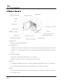
Operation manual
[INCUBATOR]
Model : IB-05G / 15G / 25G
Manual No : 00HAA0001141 ( Version : 5.0 )
This operation manual describes the important subjects to maintain
the product’s functions and to use it safely. Especially, be sure to
read <Safety Precaution> carefully before you use this equipment.
Please keep this manual close to the equipment to use it after
reading through it once. Please place it where the new user can
find it easily for the safety use when you hand over or lend the
equipment to others.
Page
1
Thank you for purchasing Jeio Tech’s product.
This operation manual forms a definition of warning marks
according to the level of importance and danger in order to use
the product safely and correctly and prevent the users from
accidents or injuries. Hence, please use the product in
accordance with the instructions.
Safety Notice
1. Caution
This product can cause a big accident in case of improper use of inflammable
and combustible solvents in the chamber. Also, operation in the high
temperature might cause a mechanical trouble and quality deterioration due to
the function and the characteristic of the product.
Safety Precautions
“Danger” means that the user may have
serious damage and even die by improper
handling on this unit.
“Warning” means that the user may have
serious damage by improper handling on this
unit.
“Caution” means that the user may have minor
damage and unit may have physical damage
by improper handling on this unit.
Page 2
Although Jeio Tech thoroughly investigates the possibilities of
dangerous situations from using the product, it is not possible to
know every single danger. Hence, precautions described in this
manual do not cover all the dangerous conditions.
However, you can operate this product safer when you follow the
directions in this manual. Please, be sure to pay attention to the
directions and be cautious so that a mechanical trouble or an
accident would not be occurred.
2. Warning mark of product
The most important thing of the warning is a warning label attached to the
product. It is located in front of the door.
Be fully aware of the warning contents during operation.
※ Please change to the new warning label when it is unreadable from wearing out. Please
request the new label to us.
Copyright 2007 Jeio Tech Co., Ltd. ALL RIGHT RESERVED.
Page
3
CONTENTS
Page 4
1. Use and Feature ………………………………………………
5
2. Installation ………………………………………………………………
6
3. Notice ……………………………………………………………………
7
4. Name of the parts …………………………………………………
8
5. Operating Controller …………………………………………………
11
6. Maintenance …………………………………………………………
18
7. Dealing with Abnormal Condition …………………………………
19
8. Guarantee ……………………………………………………………
20
9. Equipment Disuse ……………………………………………………
20
10. Specifications ………………………………………………………
21
11. Install lab tracer ……………………………………………………
22
12. How to use lab tracer ……………………………………………
23
1. Use and Feature
1) Use
(1) This Incubator is used for cultivation of thermopile micro organism and normal micro
organism like e coli and bacteria.
(2) This Incubator is used for tissue of plant and animal, activating sperm and egg and
determination of germfree of sterilized culture medium.
(3) This Incubator is good for constant temperature test like test of plant storage, environment
variation.
2) Feature
(1) This multi purpose incubator for Biotechnology, pharmacy, medical, chemical, and biology.
This unit has firstly developed CLS (Custom Logical Safe)-Control system for convinces in
use and safety to user.
(2) CLS-Control System means “Control system which has logical safety device specialized for
individual model”. Laboratory must have Thermal safety secure because there are a lot of
inflammable reagent. This system is highest safety secure control device (patent No.
0397583, 0328729) and makes the unit suitable for this kind of environment.
(3) This unit is designed to stop the Heater and Blower in order to protect the user from heat
when its door opened while it works.
(4) This unit has insulation for high temperature in the outside of the inner chamber and inside
of the door and also has Chamber Silicone door for high temperature therefore insulation is
perfect and heat lose is very low.
(5) Triple observing window is good for insulation and observe. This is Optional
(6) Uniform temperature in the chamber is made by special design.
(7) Safety circuit is used to protect the instrument from over charge and over temperature of the
heater.
Page
5
2. Installation
(1) Scope of delivery.
Main body(1set), Operation manual (1EA), Fuse (2EA), Shelf(2EA), Shelf guide(4EA) ,
Communication CD(1EA), RS-232 Communication cable(1EA)
(2) This unit will work correctly on proper power supply. Please check power supply and ID
Plate information are the same. User must use power supply connected earth and power
cord must be connected to wall outlet supplying ground point.
We don’t have any responsibility for accident and lose of personal and asset if the ground earth is not
connected.
(3) Please install the unit in the flat place where prevent vibration and shock.
(4) Please let the unit avoid heat source and direct sun light and let the unit located in ambient
temperature range in 5°C ~ 40°C relative humidity lower than 80%.
(5) Please don’t install the unit where water and organic solvent is easily penetrates in the unit.
They cause short circuit.
(6) Please don’t install the unit in dangerous place. (Where there are flammable gas and
explosive material)
(7) Please secure enough space for installation because the door of it opened 180°.
(8) Do not install near to instruments of strong high-frequency ( high-frequency welding
machine, sewing machines, SCR Controller for big capacity)
(9) This unit is quite heavy. Please move the unit with proper moving tool or 2 people together.
(10) Power cord should includes Ground terminals when installing the instrument.
(11) Install the instrument near to consents for easy usage.
Please think about the safety of user and instrument when you find out a place to install.
Page 6
3. Notice
(1) Please don’t touch Power cord and electric part with wet hand.
(2) Please don’t put explosive and flammable chemicals (Alcohol, Benzene and etc) inside of
the oven.
(3) The samples inside of the oven are very hot when the oven is works and for a while after it
stops. Please take safety glove when you touch samples.
(4) Please don’t set flammable materials near by oven.
(5) Please don’t pour water on the unit directly when you clean the unit.
(6) Please don’t put some conductive and flammable materials through ventilation or power
supply port. It is dangerous and causing fire and electric shock.
(7) Circuit and electric component used in this unit are developed by Jeio tech. Please don’t try
to repair by yourself. Wrong combination of electric part may cause fire. You must ask to
official Jeio tech dealer or distributor in your region.
Don’t put explosive and flammable materials inside of the Chamber.
Page
7
4. Name of the parts
(1) Main body
Made by iron plate and painted.
(2) Ventilating hole
It changes air volume of ventilation. It’s very hot, please wear safety glove when you need
to adjust it. The safety gloves must be dry. Wearing wet gloves cause burning and electric
shock.
(3) Shelf level adjustor
Shelf level is easily adjustable by the size of sample.
(IB-05G→8 levels, IB-15G→12 levels, IB-25G→14 levels)
(4) Shelf
It’s made by Stainless steel wire. It’s easy to clean and ventilation is good. The surface of
it is electrically polished therefore it has beautiful face good anti-corrosion.
(5) Door
There are air barrier between door surface and insulation of the door. Therefore the surface
of the door is cool.
Page 8
(6) Inner door
User can observe the inside of the chamber through this transparent and made by
reinforced glass inner door. This prevent environment inside of the chamber from exposure
to outer air then polluted. turn the handle of glass door to clockwise rotation to close the
door and to the opposite way of clockwise rotation to open the door.
(7) Door Handle
It is Door handle for door opening.
(8) Magnetic Packing
Used for shock absorber and double- air tightness.
(9) Chamber
It’s made of stainless steel and there are Blower, Heater, Temp. sensor and Temp.
regulator inside of the chamber.
(10) Temperature Controller
This has a Micro processor (CPU) which has Digital PID Auto tuning function. It also has
temperature compensation function for temperature sensor and the highest class safety
level control system such as heating volume controller.
(11) Over temp. Limit.
If the heater temperature rises higher than set temperature it cut the power of the
temperature controller, makes the over temperature LED blinking and alarming beep
sounds. If you resume the operation, please set knob of it about 15% higher than set
temperature and press Start/Stop switch ones then check run led of temperature controller
is on.
(12) Inner Door packing
A silicone rubber for high temperature keeps high air sealing.
(13) Control panel
Controller and electric component are there.
Page
9
(14) Main switch & Fuse
This is the switch for main power. Fuse protects the instrument from electric shock. Please
check out correct power supply when you replace Fuse.
(15) Communication port
User can monitor and remote control this unit by PC. Data print out through PC printer is
also available. The unit can be connected to PC’s com1 and com2 port through RS-232C
protocol cable.
(16) Foot
This adjusts level of the instrument.
(17) Inner Door limit switch
It’s installed inside of the unit. The Logic IC of this switch put off the main switch. This cut
off all 2 phase currency in the instrument therefore heater and blower stops for safety of
user. Door LED blinking to indicate the door is opened. If the door is opened more than 1
minute then the alarming buzzer sound in order to inform the user that the door is opened
for a while. Run LED is on by closing the Door and put
Page 10
button.
5. Operating Controller
1) Features
(1) CLS-Control System temperature and heater output are controlled in Main CPU which
can do precise PID calculation. All control for safety is conducted by selective
functional Logic IC which is installed separately. This is designed to conduct safety
performance against any electric and electronic shock on the unit.
(2) CLS-Control System shuts down all 2 phase power supply to each part immediately
and informs user instability by audio and visual device then keeps in safe mode until all
instability conditions removed.
(3) CLS-Control System gives user two choice, one is resume operation of the unit and
another is keeps the unit in standstill when the unit operation were terminated by
power failure and then recovered.
(4) CLS-Control System, the safety device designed to keep very small amount of
currency (only 5V, 10mA) in contact point. This makes durability of contact point very
long.
2) Name and operation
The instrument includes CPU for possible digital PID-Auto tuning software and the best safety
controlling device for temperature- compensating function for Pt-100Ω sensor and heating
control.
Page
11
(1) HEATER LED
It shows Heating function is “ON”
(2) Auto Tune LED
Flickering begins on Auto-tuning.
(3) Wait On Timer LED
This is the LED indicating operation start time. The LED is blinking when the timer works and
the LED off when the timer is in waiting condition.
(4) Wait Off Timer LED
This is the LED indicating operation stop time. The LED is blinking when the timer works and
the LED off when the timer is in waiting condition.
(5) Door open LED
LED is on by opening the door.
(6) Over heating alarm LED
If the heater temperature rises higher than set temperature it cut the power of the
temperature controller, makes the over temperature LED blinking and alarming beep
sounds. If you resume the operation, please set knob of it about 15% higher than set
temperature and press Start/Stop switch ones then check run led of temperature
(7) Temp. button.
This button is for temperature setting.
(8) Timer button.
This button is for timer setting.
(9) Up button.
This button is for increasing set value.
(10) Down button.
This button is for decreasing set value.
(11) Enter button.
This button is for saving value after varying set value.
(12) Start/Stop button.
This button is for start/stop of unit and for resuming operation after removing some
unstable factors when operation is terminated because of it.
Page 12
(13) Lock button.
This is to lock controller buttons.
(14) Auto Tune button.
The auto tune begins if you press this button for 1 second.
(15) RUN LED
This LED indicates Work/Stop state of unit. It turns on when the unit runs and turns down
when the unit stops.
(16) SV display
This display is for showing set temperature and showing remaining time when the timer
function is activated.
(17) PV display
This display is for showing present temperature.
3) Temperature setting way
(1) Press
button. Set temperature value (SV) is blinking. This means you can vary set
value.
(2) Press
button to vary digit number and press
button when you save the
value.
(3) It goes back to previous state without saving if you don’t touch any button for 10 seconds.
(4) Press
button again when it is in SV set state then following additional functions are
activated
Page
13
4) Additional function of
button
(1) Favorite values can be stored at Sv.1, Sv2, Sv3
for each operation.
Press
2 times and set temp. values by
pressing
and
, and conclude the
setting by pressing
Set temperature is saved on memory and set
temperature varies Sv1, Sv 2, Sv 3 are applied
the same.
Press
button repeatedly then Sv1, Sv2,
Sv3 are shown and temperature unit set mode
shown by pressing 5 times repeatedly.
(2) This is a function vary the unit of temperature
value.
Initial display is ℃ and it can be varied ℃ and
℉ by pressing
and
buttons.
(3) Next mode is shown by pressing
6 times.
This compensates the temp. value errors.
Requested values are put on PV display. Move
to the next mode by pressing
and
00000buttons.
PV
is put on the SV display and can be set
as exactly as shown on thermometer. Set the
value by pressing
and
conclude the setting by pressing
Page 14
, and
5) How to set Timer.
(1) Press
button.
Timer (On Timer / Off Timer) is shown on PV and time is shown on SV display. Set time by
pressing
button and Save by pressing
button.
(2) W/ON LED turns on with Beep sound after finishing wait on timer set.
(3) Press
button two times. You can set wait off timer.
Set time by pressing
button and save and finish by pressing
button.
(4) W/OFF LED turns on with Beep sound after finishing wait on timer set.
(5) The function of Timer is as follows.
Page
15
Temperature
Time
Wait on Timer
Wait off Timer
☞ Wait On Timer
- The unit begins to work when the time programmed into ‘Wait On’ is attained.
- Maximum is 99hr 59mim. and minimum is 1min.
☞ Wait Off Timer
- The unit stops when the time programmed into ‘Wait Off’ is attained.
- Combination of Wait On Timer & Wait Off Timer.
- The unit works as picture above
(6) Set off Wait on/off Timer
Press
pressing
button one (Wait on Timer) or two (Wait off Timer) times and set Z(0) by
and finally press
6) Additional function of
to set off.
button.
The following Auto Run function is shown by pressing
button thee times repeatedly.
(1) This is for compensating function after power failure.
If you set yes the unit will run or else the unit will not run after power failure situation
finished.
Page 16
7) Auto Tuning
Perform Auto Tuning in order to get precise and rapid temperature control. PID value saved
automatically after Auto Tuning.
(1) Set temperature you want.
(2) Press
button for a while(3seconds) then Auto Tune shown display like right hand side
picture and A/T LED blinking.
(4) RUN LED is on by pressing
button and Auto Tune is working with flickering A/T LED.
(5) Auto Tune time is various according to installed environment. LED turns off after finishing
Auto Tune and Present temperature & Set temperature meet.
8) Key Lock
This is to lock controller buttons.
(1) Press
button for a while (3seconds), then Lock function is set with Beep sound and
the unit wouldn’t corresponding any more key pressing.
(2) In order to deactivate this function please Press
button for 3 seconds again.
(3) This protects improper pressing of the controller buttons while operation.
Page
17
6. Maintenance
(1) Turn off the main power switch and pull out a power plug from wall outlet.
(2) Remove all liquid in the bath.
(3) Wash with soft cloth containing neutral detergent.
(4) Wash with soft cloth containing distilled water.
(5) Dry with dry cloth.
(6) Don’t use organic solvent.
(7) If user try to clean this unit with other method not mentioned on this manual please contact
us in order not to damage to the unit.
(8) Put on Safety glove for harmful chemicals and Safety Mask for harmful gas and then wash
out pollutant with dried cloth when harmful chemicals and gases are spread out on the unit.
Page 18
7. Dealing with Abnormal Condition
1) Check points when the unit doesn’t work.
(1) Check out power supply.
(2) Check out fuse if off.
(3) Check out Run LED on display is off.
Please press Start / Stop button if it is off.
(4) Please check the power is out.
2) Malfunction check list.
Malfunction symptom
What to check and what to do.
Buzzer sound
If Door is opened, Press START/STOP Switch once and check out Run
continuously(1)
LED turns on.
Check if there are machines generating strong high frequency noise
No temperature
control.
near by the unit.
Check if Some contaminants are in the control panel.
Do Auto tune again.
Air circulation is not
made in the chamber
Check the door switch (open and close the door 2~3times)
Check the blower works correctly
Check the Impeller of blower is OK inside of the chamber.
Abnormal sound
Open the back plate of the instrument and Check the Impeller of Blower
touches any part.
Check the Main power Switch is on.
No power
Check the power supply is on in the room.
Check the power failure.
Check the fuse is OK
Temperature wouldn’t
rise
Check the RUN LED is on.
Press the START/STOP Switch once if the RUN LED is off.
Check the door is opened.
Check the Over temp. limit is set lower than current set value of the
Buzzer sound
continuously(2)
temperature.
If it is, please set the value of the Over temp. limit at least 15% higher
than PV.
Press the START/STOP Switch once and the check the RUN LED.
☞ If you can’t recover the instrument please call a repair service.
Page
19
8. Guarantee
1) Warranty service duration
It covers for 1 year since you purchase the unit and then after the duration you need to pay for
service parts.
You can get faster and precise service by telling us the information as below.
*Date of Purchase
*Serial number
*Symptoms and regions of break-down
*Using environment
2) The case user can’t get warranty service.
*wrong operation by users.
*Wrong usage and management.
*Wrong remodeling and repair by users.
*Break down by natural calamity.
*Different usage from operation manual
9. Equipment Disuse
keeps an abolition way if disposes of a product or parts, and please dispose of abolition.
An abolition way of main configuration parts
Configuration
Model
Weight (Kg)
Size (mm)
An abolition way
Main Body
IB-05G
45Kg
595×555×745
commits to a businessman
Main Body
IB-15G
55Kg
675×605×855
treating
Main Body
IB-25G
62Kg
805×655×885
Parts
Page 20
a
waste,
and
please dispose of abolition.
10. Specifications
Model
IB-05G
IB-15G
IB-25G
Chamber volume
60L
102L
151L
Temperature 5℃ to 40℃
Permissible
Maximum relative humidity 80%
environmental condition
Altitude up to 2,000m
Range
Amb.+5℃~70℃
Uniformity
±0.4℃ at 40℃
Accuracy
±0.1℃ at 40℃
Controller
Digital PID auto tuning
Sensor
Pt100Ω
Heat up time
40℃ Within 45 min
Internal
Stainless steel, 0.8t
External
Steel, 0.8t power coating
Shelves
Stainless steel wire, electro polished
Insulation
Nonflammable polystyrene (20mm/10mm)
Door gasket
Foamed silicone rubber
Inner door
Tempered safety glass (5mm)
Ventilation slide
Stainless steel, dia. 38mm×1EA
Temperature
Material
Safety device
CLS(Custom Logical Safe)-control system, ClassⅡ
Over temp. limit
Hydraulic over temp. limit
Incoloy fin,
Incoloy fin,
Incoloy fin,
230V/300W
230V/500W
230V/700W
115V/300W
115V/500W
115V/700W
Internal(㎜)
400×360×420
480×410×520
610×460×540
External(㎜)
595×555×745
675×605×855
805×655×885
Inner door(㎜)
t5×415×455
t5×495×555
t5×625×575
AC230V,
AC230V,
AC230V,
50/60Hz, 1.3A
50/60Hz, 2.2A
50/60Hz, 3.1A
AC120V,
AC120V,
AC120V,
60Hz, 2.8A
60Hz, 4.6A
60Hz, 6.4A
45kg
55kg
62kg
Heater
Size
(W×D×H)
Electric requirement
Weight(net)
Page
21
11. Install Lab Tracer
(1) Insert Installation CD and the software starts installation automatically.
(In case of no automatic running, run “SETUP.exe” file in CD.)
(2) Click “Next” button to choose destination of installation. (Default folder recommended)
(3) Click “Install” to start installation.
(4) Lab Tracer icon will be created on desktop after installation successfully.
(5) To start Lab Tracer, double click the icon.
Standard
Recommend
Beyond Microsoft Windows 98
Microsoft Windows 2000, XP
CPU : Beyond P-II 233
CPU : Beyond P-III 300
RAM : Beyond 32M Byte
RAM : Beyond 64M Byte
Caution : If Windows 95 or 98 OS system is installed, time delay can arise between
measuring time.
Page 22
12. How to use Lab Tracer.
(1) Connection for communication
Click Comm → Connect and your PC and equipment start connection of communication.
(In case of no connection, click Comm → Port and try to other ports.)
“On Line” displays on the bottom of the software, once communication is connected
successfully. The window consists of 2 separate windows. Window on the top displays
Temperature set point and actual temperature and window on the bottom displays output
value of heating in graph mode.
(2) View
① If you click View → Parameter, window displays actual temperature, temperature set
point and output of heating by graph and figures.
Page
23
② If you click View → Status, additional separate window appears below showing actual
temperature and set point window. Operating, Auto Tune, Program, Over Temp., Level,
and etc display on this window.
The following picture is a monitoring window after choosing Status and Parameter in
View menu.
User can monitor operating process through three divided interfaces. (Graph,
Parameter, Status)
☞ Graph displays;
Actual temperature (Red line) and set point (Blue line) on the top of separate
interfaces.
☞ Status says that;
- Operating represents the unit is Running.
If blue line is Hi, the unit is On(operating). If blue line is Low, the unit is Off.
- Auto Tune displays whether the unit performs Auto Tuning or not.
- Program displays whether the unit is in programmable mode or not.
- Over Temp. displays over heating condition of a unit.
- Water Low displays whether Water Level works or not.
In case water is at the low level, blue line is Hi position and low position under
normal condition.
- Cooling displays whether compressor works or not.
Page 24
③ Parameter interface has following values;
☞ PV is actual temperature.
☞ SV is temperature set point.
☞ Heat is output value of heating element.
☞ Run Time says operating time after you press
button.
☞ Wait On Timer, Wait Off Timer displays remained time from setting time.
☞ Power Frequency displays frequency of current power.
(3) Menu icon
ⓐ
ⓑ
ⓒ
ⓓ
ⓔ
ⓕ
ⓖ
ⓗ
ⓘ
ⓙ
ⓚ
ⓛ
ⓜ
ⓐ File Open (Ctrl + O)
To open saved graph.
ⓑ File Save (Ctrl + S)
To save proceeding graph.
ⓒ Connect (Ctrl + C)
To connect unit and PC via RS-232 communication.
ⓓ Disconnect (Ctrl + D)
To disconnect RS-232 communication.
ⓔ Exit (Ctrl + X)
To terminate Lab Tracer.
ⓕ Print (Ctrl + P)
To print saver graph or proceeding graph. (refer to p30)
ⓖ Preview
To preview before printing.
ⓗⓘ Scroll icon
To scroll graph.
ⓙⓚ Auto Trace On/Off
If you want to fix and monitor the last point of graph on the center of windows, Click
Auto Trace.
ⓛⓜ Auto Span On/Off
Set Y axis(temperature range) of graph manually or automatically. You can put values of
range if you choose manual.
Page
25
ⓝ
ⓞ
ⓟ
ⓠ
ⓡ
ⓢ
ⓣ
ⓤ
ⓥ
ⓦ
ⓧ
ⓨ
ⓝ To display Status interface. (Ctrl + T)
ⓞ To display Parameter interface. (Ctrl + R)
ⓟ Panel View
When you click Panel View, the same appearance of display panel of unit pops up and
you can control the unit by the pop-up window.
ⓠ Set Pattern of Program Run.
Set Pattern of Program Run and makes unit in a programmable operation.
Maximum number of pattern is 100 during 99hour.
- Program function can be controlled only by PC.
ⓡ Program Run.
Program Run must be set in the main unit.
ⓢ ~ ⓥ Zoom In/Out.
ⓦ ~ ⓧ To convert temperature scale from ℃ to ℉ or vice versa.
(Note: Temperature scale of main body is not changed even though you convert
temperature scale from Lab Tracer. To changer temperature scale of main body, you
must change setting value of controller in main body.)
ⓨ To erase graph.
(4) Print
Page 26
① Print range
- All : Print a total page.
- Print the screen : Print the current screen. (In case Graph, Status, Parameter Frame on
the window, they are printed. If not, they are not printed.
- Current page : Print a page of the currently main screen.
- Selected pages : Print selected page(s).
② Number of copies
- Maximum number of copies are 100 by scrolling up and down button.
③ PV print interval
- If you tick this option, PV and SV are printed in text mode.
④ Memo
- Can write brief memo on print. Maximum to 60characters.
⑤ Select Print
- Can choose a printer.
(5) Preview and print
In case Print at equal intervals is ticked, PV and SV is printed in a regular interval(see above)
Page
27
when you see preview and printing. If user wants to check a certain point, move curser to
the point and click. Green line with PV and SV will be printed on the copies. (see above)
① Last Point Delete
- Delete last set point.
② All Point Delete
- Delete all set points.
③ Zoon in / out
- Zoon in or Zoon out.
(6) Display
Performance of Display window is same as that of main display panel.
If communication via RS-232 between PC and main body is successful, user can control
main body with your PC at a distance.
(7) Pattern Program
Pic 1. Main Lab Tracer
The following window will be open in case click PRG icon or Pattern -> Pattern settings in
menu.
Page 28
Pic 2. Pattern Program
In case you move mouse and click a certain point like pic 3., temperature set point and time,
step number display on left side of window.
Pic 3. SV Pattern after clicking a certain point of window.
If you want to edit the selected point, Drag & Drop the selected step (blue color). It is very
convenient to use short-keys when you want to change temperature and time. Because
temperature can be adjusted 1 degree unit and time adjusted one minute unit.
① Short-key
↑ : Increase temperature by 1 degree.
Page
29
↓ : Decrease temperature by 1 degree.
← : Decrease time by 1 minute.
→ : Increase time by 1 minute.
Alt + ↑ : Move an edit point to the right (the following step)
Alt + ↓ : Move an edit point to the left (a previous step)
Alt + ← : Move an edit point to the left (a previous step)
Alt + → : Move an editing point to the right (the following step)
② Last step delete
- Delete last set step.
③ All step delete
- Delete all set steps.
④ Pattern save
- Save programmed pattern.
- File extension is PIT.
- Choose a folder and write file name. Then, click save button.
⑤ Pattern open
- Choose a pattern file and click open.
⑥ Start
- Click the START icon to operate unit after Pattern is set.
Note: i) If the main body is under abnormal condition such as Door Open, Over Temp.
and etc, the main unit will not work.
Pic 4. Step information and control option.
Page 30
- If you put and set number of pattern repetition, the main body will work as
programmed.
- If you tick “Deleting the previous data” and press start icon, previous data will be
erased. Please, be cautious.
※ Caution
- Maximum operating time is up 99 hours.
- If you program total working time over 99 hours, the unit does not perform in Program Mode.
Especially be cautious when you program pattern repetition.
- Please, be aware of specification and program time and temperature.
- If you program pattern over equipment performance, the units can not work properly.
Page
31