1
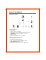
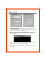
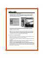
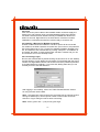
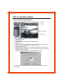
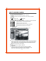
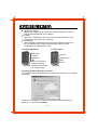
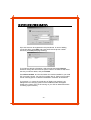
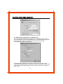
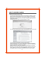
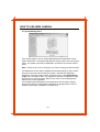
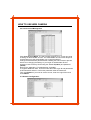
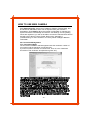
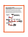
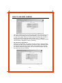
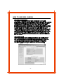
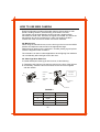
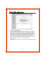
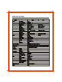
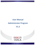
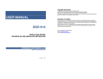
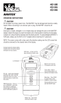
INSTRUCTION MANUAL
WEB CAMERA
Please read this manual thoroughly before use, and keep it handy for future reference.
PRECAUTIONS
Installation ------------------------- Cleaning ----------------------------Do not install the unit in an extremely
hot or humid place or in a place
subject to excessive dust,
mechanical vibration.
Clean the unit with a slightly damp soft
cloth.
Use a mild household detergent.
Never use strong solvents such as
thinner or benzine as they might
damage the finish of the unit.
The unit is not designed to be
waterproof.
Exposure to rain or water may damage
Retain the original carton and packing
the unit.
materials for safe transport of this unit
in the future.
FCC COMPLIANCE STATEMENT
THIS CLASS B DIGITAL APPARATUS COMPLIES WITH CANADIAN ICES-003.
NORME NMB-003 DU CANADA.
-2-
PRODUCT INFORMATION
The Intelligent Network Web Camera provides an advanced solution for
retrieving video over computer networks, including the Internet. The Web Camera
compresses Video, and then transmits the compresses video over computer
networks or telephone lines at speeds up to 30 images per second. In addition,
the Web Camera provides audio and alarm information from the remote site.
There are one sensor input and one alarm input.
The user can listen in on the remote site with the audio input. The Web Camera
is capable of remotely controlling pan, tilt, zoom, and focusing cameras. All of the
web camera features are accessible through the web camera browser, allowing
users to access and control their systems any time from virtually anywhere.
1. Features
A) Monitor live video images transmitted in real-time
Remote monitoring up to 30fps live video images using unique algorithm
Low network bandwidth requirement : 3KB per image typical
Three-levels of resolution : 640x480, 320x240, 160x120
:Sine a 640x480 resolution image is composed with two consecutive fields
of interlace type scanning, there may exist some motion artifacts around a
moving object.
Four-levels of image compression
B) Simultaneous video and audio signal transmission
Monitor voices and background sounds via one
C) Supports network environments
Ethernet or Fast Ethernet interface for LAN card Internet
Modem interface for standard telephone line
D) Easy software upgrades from anywhere
Upgrade software at remote sites using the web camera browser
E) E-mail transmission ensures important events are not missed
The web camera can be transmitted to assigned e-mail addresses
whenever a sensor detects an input signal
F) Additional convenient features
One digital sensor input and one alarm output
RS485 interface for Pan/Tilt/Zoom/Focus control
Each function can be set remotely using the web camera browser
-3-
PRODUCT INFORMATION
2. System Configuration
3. System Components
Web camera
Adapter (12VDC, Min 700mA)
Web Camera Installation Diskette for Modem Connection
MINIDIN-8/DB-9 Converter for Modem Connection
User Manual
LAN cross cable
RS485 Terminal-Block for P.T.Z Connection
4. Monitoring System Requirements
OS: Microsoft Windows 98, 2000
CPU: Intel Pentium II Celeron 266MHz or higher
RAM: 32MB or higher
VGA: AGP, Video RAM 4MB or higher
Web Browser: Internet Explorer 5.0 or higher version
-4-
INSTALLATION
Front Panel
Alarm
RX/TX
Power
Back Panel
Network
DC12V
Video Out
Reset
Rs232
1/0 Port
1. Connection via LAN
1.1 Cable
Connect LAN cable to the network port on the back panel.
1.2 Power
Connect the power cable to the DC12V port on the back panel.
(The web camera has been booted normally if POWER LED blinks once
within 10 seconds.)
1.3 PC Setup
Use a PC that can network with the web camera without a router.
(From now on, this particular PC will be referred to as "PC.")
1.4 Configuring PC Network
Under Start in Windows, go to Settings, Control Panel, and then Network
Setting. In the Configuration tab, select the TCP/IP and then click Properties.
Make a note of the existing network configuration values since you will need
to restore them in Step 1.8. Modify your network configuration as shown below.
Note : You may need to reboot after this step.
Example) IP Address: 192.168.1.150
(In fact, fourth address number may be any value from
1 to 254, except 129.)
Subnet Mask: 255.255.255.0
-5-
INSTALLATION
1.5 Verifying Network Setup
Under Start in Windows, go to Programs, then choose MS-DOS Prompt.
Show Graphic of DOS Prompt and Graphic of DOS Prompt with command.
Enter the ping command (ping -t 192.168.1.129).
Note : By sending a packet to the specified address and waiting for a reply,
the PING (Packet Internet Groper) can determine whether a specific IP
address is accessible.
If the ping utility returns "Reply from 192.168.1.129...," it means that the
address has been set and communication is established.
If the ping utility continually returns "Request timed out," go back to Step 1.2
and try again.
-6-
INSTALLATION
1.6 Administrator Configuration
Start your Web browser and enter "http://192.168.1.129/admin_ login.html"
in the location/address field. The web camera Administrator Login Page will
appear. Enter a login ID and password. The default ID is admin, and the
password is 12345. Refer to the " The web camera Administration Page"
section for details.
1.7 Configuring the Web Camera Network
Move to the Network Config menu in the Administration Page and modify IP
address, gateway, and subnet mask. The Web Camera will reboot after you
press Submit, and the POWER LED goes on and off 10 times. After five
seconds, the POWER LED will go on and off again. This means that the
system has completed the new network configuration. Refer to the "Web
Camera Administration Page" section for details.
1.8 Restoring PC Network Configurations
Restore the network configurations to the original values in Step1.4.
You may need to reboot.
1.9 Verifying Networking
Run the ping utility again with an IP address modified in Step 1.7. In case the
networking does not work, disconnect and reconnect the power cable then run
the ping utility. If the problem occurs again, press the reset pin button (located
on the back panel) with a sharp pin for one second and launch Factory Reset.
Then go back to Step 1.4 and try again. Refer to the "Appendix II.
Troubleshooting" for the instructions on Factory Reset.
-7-
1.10 Accessing the web camera
When you start your Web browser and enter "http://modified IP Address"
(modified in Step 1.7) in the location/address field, the Web Camera
Web Camera Browser will be automatically installed and launched with a
note of authentication dialog box.
Check to see whether the images have been transmitted by the Web
Camera without any problem. Refer to the "Web Camera (Web Camera
Browser)" section for details.
Note : Once you modify the IP address, all the settings are automatically
saved. You do not need to go through the steps again, even if you unplug
and then plug the unit back in. However, follow the Administration Page
Instructions if you want to change the IP address again.
2. Connection via Dial-up Modem
When a local network connection is not available, you can connect the web
camera through telephone line at a remote location.
The Web Camera can be connected via LAN and modem at the same time.
2.1 Cable
Connect an external modem (Hayes compatible, 33.6kbps or higher) to the
MINIDIN-8 connector of the RS232 port on the back panel.
For this connection, MINIDIN-8/DB-9 converter is required. The modem
should be connected with a telephone line. In case of using LAN and modem
at the same time, connect a LAN cable to the network port on the back panel,
and refer to the "Connection via LAN" section in the previous chapter for the
instructions on network setup.
-8-
2.2 Power
First connect the power cable to the installed modem, and then supply the
power to the web camera using a provided adapter(12VDC, Min 700mA).
The Web Camera has been booted normally if POWER LED blinks once
within 10 seconds. Right after this, the web camera executes a modem
initialization command and makes the modem ready to receive a call.
2.3 Installing a Browser for Modem Connection
Another modem should be installed in a local PC which will be connected
via modem to the Web Camera at a remote site. (From now on, this particular
PC will be referred to as "PC.") Insert The supplied installation diskette to the
PC, and install the web camera base by running "setup.exe." If installation is
successful, the folder "C:/web camera base" has been created, and you can
find a shortcut icon on the desktop screen.
2.4 Connecting (Login)
Run the web camera base by double clicking the shortcut icon on the desktop,
and the following "Login" dialog box will appear. Fill the blanks with the phone
number of a target Web Camera, and the user ID and the password provided
by an administrator accordingly. If you press OK, dialing starts and you can
remotely access to the Web Camera.
After logging in successfully, refer to the "Web Camera Browser" section
for using the web camera base.
Note : The target web camera should be connected with an external modem
through its RS232 port, and the phone number of the modem should be
entered in "Login" dialog box above when connecting.
Note : Enter "guest" and " " (null) for the guest login.
-9-
HOW TO USE WEB CAMERA
1. Web Camera(Web Camera Browser)
Power Button
- Quits the program.
System Status
- Displays the current date/time and alarm status.
Utility Buttons
- Selects a camera and functions, including connection/disconnection,
audio on/off, image adjustment, and PTZ control.
Image adjustment page
start the web and enter "admin_browser.html" Page of the IP address
assigned for your web camera (e.g.,192.168.1.129/admin_browser.html)
in the location/address field.
The default login ID is admin, and the Password is 12345.
The "Web Camera Image adjustment Page" will be displayed if login is
successful.
- 10 -
HOW TO USE WEB CAMERA
Screen Enlargement/Shrink Button
- Selects a screen size (640x480, 320x240, 160x120).
Title Bar
- Displays the title of the location where the web camera is installed.
Multi task
◀ Always On Top
◀ Minimize
1.1 System Status and Utility Buttons
The warning lamp turns orange if a sensor is activated or motion is detected.
◀ Toggles between connection/disconnection.
◀ Toggles the audio-output on/off.
◀ Opens/closes the window for image adjustment.
◀ Opens/closes the window for PTZ control.
1.2 Camera Screen
OSD Switcher
- Every time this button is double clicked, the OSD mode switches between
None / Camera Title + Time / Camera Title + Time + Transmission Status.
- Time, Camera Title, and Transmission Status are displayed only when
the screen size is 320 x 240 or larger.
Time
- Displays the time the image is captured.
Camera Title
- Displays the title of location where the camera is installed.
- The camera title can be changed on the Administration Page.
Refer to the "Administration Page" section for details.
- 11 -
Transmission Status
- Displays the image size (in bytes), the number of images per second,
and the data transmission rate (in Kbps).
No Video
- "No Video" is displayed in the center of the camera screen when The
image part of the camera is not working.
Not Activated
- "Not Activated" is displayed in the center of the camera screen when
the user selects "Off" for Video Channel State under the Video
Configuration of Administration menu.
1.3 Image Adjustment
1.4 PTZ Control
Brightness
Contrast
Saturation
Hue
Revert: Cancels the
image processing
operation and reloads
the original image.
Pan/Tilt
Zoom In/Out
IRIS
Focus
1.5 Dialog Boxes for Dial-up Connection
The following dialog box appears after executing the shortcut icon for modem
connection.
The site ID and telephone number can be added, edited or deleted by
pressing ">>", and selecting Setup.
- 12 -
Up to ten sites can be registered in this phonebook. In case of adding
connection sites, press Add, and enter site ID and its phone number.
And then press OK.(Next page drawing)
If you want to edit site information, select the site and press Change.
And then change the site ID and its phone number. To delete a site, select
the site you want to delete, and press Delete.
Press Show modem, and check whether the modem installed in your local
PC is correctly chosen. You can find a combo box of "Select your modem"
and an entering space of "Modem initialization command" at the bottom.
If you press ">>" next to the combo box of "Select your modem", the
dialogue box for changing options of the installed modem will appear.
(Refer to the "Help" menu of OS running on your PC for detail instructions
on setting up the modem.)
- 13 -
1.6 Administration Dialogue Box for Modem User
The web camera administration dialogue box is available only if you log in
as an administrator (with an administrator's ID). After administrator login has
been successful, double click the title bar of the web camera base.
The following dialogue box will appear.
The information of dialogue box above is equivalent to the one of " web
camera Administration Page" accessible by using a web browser. Refer to the
"web camera Administration Page" section for the instructions on setting up
each menu.
- 14 -
HOW TO USE WEB CAMERA
2. Web camera Administration Page
The web camera administration page is the web page accessible by a web
browser, where the administrator can control the settings at a remote site.
Start the Web browser and enter "admin_login.html" page of the IP address
assigned for your web camera (e.g.,192.168.1.129/admin_login.html) in the
location/address field.
The default login ID is admin, and the Password is 12345.
The "web camera Administration Page" will be displayed if login is successful.
The web camera Administration Page has eight sections :
System Management, User Account Management, Network Configuration,
Connection Management, Digital IO Configuration, Serial Port Configuration,
Camera Configuration, and PTZ Configuration.
Additional sections include System Upgrade, System Reboot, Connection
Monitoring, Launch web camera base, and Logout. Click each menu item to
select it. Adjust the settings by clicking Submit after setting up the values.
Click Reset to ignore the modified values and show the current settings.
- 15 -
HOW TO USE WEB CAMERA
2.1 System Management
Click System Mgmt to set up System Management and Web Base Launch
Option information. The System Management sets the date, time, and system
name. The system name will be displayed in the title bar of the web camera
base.
Note : Check the box next to Change if you want to change the date and time.
The Web Base Launch Option establises the default settings of web camera
base when the user first accesses the system : Window Size (640x480,
320x240,or 160x120), Audio On/Off, and Guest Login. If the Default Guest
Login box is unchecked, then only registered users who completed the login
procedures can use the system. Refer to the "User Account Management"
section for the user registration.
The sample System Management and Web base Launch Option settings
above show that web camera base will display the images with the size of
320x240, guest login is available, and audio is off.
- 16 -
HOW TO USE WEB CAMERA
2.2 User Account Management
Click User Account Mgmt. The web camera supports up to 16 user accounts
including an administrator account. The administrator account must always be
used because only the Administrator can control the settings.
Change the administrator password after installing the web camera to prevent
others from changing the settings. If you forget an administrator ID and
password, launch Factory Reset using the default ID(admin) and password
(12345).
Refer to the "Appendix II. Troubleshooting" for details.
To register additional users, enter their user IDs under Login ID and passwords
under Password and then confirm the password under Re-Password.
Then click Submit. If you want to remove a user, clear the Login ID box and
click Submit.
2.3 Network Configuration
- 17 -
HOW TO USE WEB CAMERA
Click Network Config. Assign the IP Address, Gateway, Subnet Mask, and
E-mail Server addresses, which can be acquired from your network a
dministrator. Click Submit. When the network configuration is changed, the
system will reboot automatically and save the new settings. If wrong setting
values are registered, you will not be able to access the rebooted web camera
and will have to launch Factory Reset. Refer to the "Appendix II.
Troubleshooting" for the instructions on Factory Reset. Intelligent Network
Transmitter
2.4 Connection Management
Click Connection Mgmt.
The Connection Statistics and Management sets the maximum number of
connections and the maximum connection time.
If you do not wish to limit the connection time, enter '0' in the "Maximum
Connection Time in Minute" box.(Maximum guest "20")
- 18 -
HOW TO USE WEB CAMERA
2.5 Digital IO Configuration
The Digital IO Configuration sets the operation of a sensor, motion detection
and an alarm, and the alarm out condition. When an alarm is triggered or
motion is detected, an e-mail message will be sent to the e-mail address
assigned to that camera. The Web Camera warning lamp also indicate the
state of a sensor (closed or open). The sensing condition is set when a target
sensor port and a ground port on the back panel are connected (Normally
Closed), and when a target sensor port and a ground port are not connected
(Normally Open). There is one dry contact (open collector) alarm output, which
can control the switch of an external device.
330Ohm
IO Connector
LED
IO Connector
DIODE
RELAY
5V
IOConnector
4.7KOhm
- 19 -
HOW TO USE WEB CAMERA
The motion detection is set up for the camera input of the web camera, and
the value for its sensitivity has four levels between "Low" and "Very High."
In case of "Very High" value, you need to test its sensitivity first, because it
may be more likely to trigger false alarms. Refer to the "2.7 Camera
Configuration" for the instructions on e-mailing the image of a target camera
when an alarm is triggered or motion is detected.
2.6 Serial Port Configuration
Serial Port Configuration, only used for dial-up connection, sets the RS232
port setting and the modem initialization command. Set the desirable values
according to the performance of the modem to be installed. If you change
any value of serial port configuration, the web camera will reboot and open
the Rs232 port with new settings.
- 20 -
HOW TO USE WEB CAMERA
- 21 -
HOW TO USE WEB CAMERA
E-Mail Configuration includes information about e-mail recipient, e-mail
sender, sending condition, serial sending, and content of e-mail.
The number next to Serial Sending shows how many images will be
transmitted in serial order. However, the higher the number, the slower the
transmission due to the constraints of e-mail. The sending condition
includes the result of sensor activation and motion detection.
2.8 Manual Lens
When using the manual iris lens, turn the iris ring on the lens to the OPEN
position and adjust the manual iris for the appropriate range.
Adjust the lens opening for the minimum F-number yielding a good picture
under the brightest scene conditions.
The manual iris is used in indoor applications where lighting from windows
can considerably affect the light level of the room.
2.9 Video-Type Auto IRIS Lens
To install and adjust a video-type auto iris lens, do the following :
A. Thread the auto iris lens onto the lens mount on the front of the camera.
B. If necessary, solder the lens control wires to the connector supplied
with the camera.
Connector
Rib
Automatic
Pin 3
Iris Lens
Cover
Pin 1
Heat
Pin 4
Shrinkable
Tubes
Iris Control
Pin 2
Cable
Connector
FIGURE 3.
PIN
NAME
Wire Color
1
Voltage +
2
Open
3
Video
White
4
Ground
Black
- 22 -
Red
C. Plug the connector into the auto iris jack on the side of the camera.
The connector is polarized and can only be inserted into the jack one way.
D. The Camera Config should be in the Auto IRIS on position
E. Adjust the focus ring on the lens for an optimum picture.
If a picture is not visible, set the lens for proper exposure by adjusting the
ALC(automatic level control) and level on the lens.
The ALC setting can range between Average (average) or PK (peak).
A midrange setting is appropriate for most applications.
For ALC adjustments :
AVG : To slow the reaction of the lens to changing light, set the range to the
AVG setting to average the video level from the camera.
Use when there are bright spots in the picture such as lights or glare from
the sun.
PK : To increase the speed of the lens reaction to the changing light, set the
lens adjustment to PK so the lens will adjust to the brightest or peak object
in the video. Use this setting if you want to see the brightest object and not
the background objects.
For Level Adjustments :
Adjust the level control for the best picture during the day.
A night adjustment may not provide the proper setting for controlling the light
during the day.
F. Set the back focus of the camera before the final adjustment of the video
level.
If the auto iris has a gain adjustment :
If the lens oscillates between open and closed under bright lights, slowly turn
the gain adjustment counter clockwise until the oscillating stops.
Increase the light getting to the camera by adjusting the level control and
readjusting the gain control as noted in step G.
Note : The operation of sensor and motion detection should be set in advance.
Refer to the "2.5 Digital IO Configuration" section.
- 23 -
2.10 PTZ Configuration
The web camera can remotely control the pan/tilt/zoom/focus module of
the camera through an I/O port on the back panel of the system.
When networking, the Half Duplex communication line of the RS485 is
used between the web camera and the PTZ module. When communicating
by RS485, attach a termination resistor(120-150 ) on the outside to process
without errors. The IRX-100, manufactured by web camera, already has a
terminal resistor inside. Refer to the manual for each supported driver for
the detailed communication settings between the web camera and the
PTZ module.
2.11 System Upgrade
This page allows software upgrades to be done at remote sites using a
web browser, so that users do not have to come to the web camera or take
its cover off. Since wrong software upgrades may cause an unrecoverable
system failure, the web camera will ask for another password to upgrade
software. This password will be included with the upgraded software
provided by us.
- 24 -
2.12 Connection Monitoring
Connection Statistics Monitoring helps the administrator see the state of
current system and connections at a glance. This page is automatically
updated every 10 seconds, so the administrator does not need to click this
menu to get the updated information. Connection Statistics Monitoring
shows the current system version, bootstrap time, system status, system
time, number of connected users, and average frames per second.
The Currently Connected Users information is the same information as the
Current Connection Statistics in Connection Management.
2.13 Log Out
Please log out after finishing setup to keep your administration page secure.
- 25 -
TROUBLESHOOTING
Q) I cannot access the "web camera Administrator Login Page" due to wrong
network configuration.
A) After launching Factory Reset, try the installation procedures again.
The POWER LED will go on and off quickly, and Factory Reset is launched
if you press the reset pin button (located on the back panel) with a sharp pin
for about one second after connecting the power cable.
When Factory Reset is launched, all the settings, including network setup,
return to the factory default settings. Then follow installation procedures in
accordance with the instructions written in this manual.
Note : If you push the reset pin button only slightly, it will simply reboot, and
the setting you had entered before rebooting will remain unchanged.
Q) I forgot the ID and password for the administrator account, so I cannot log
into the web camera Adiminstration Page.
A) After launching Factory Reset, use the default ID (admin) and password
(12345). The network configuration returns to the factory default settings
after launching Factory Reset.
Reset the settings by following the installation procedures in this manual.
Q) The Web Camera does not launch.
A) Upgrade Internet Explorer to 5.0 or higher version.
Sometimes the web camera base cannot bring 'index.html' from the web
camera when the Internet Explorer version is under 4.0.
Q) The images are not displayed even though the web camera has been
launched.
A) Update the V3 program to the latest version or terminate the program.
This will occur when the V3 (Ahnlab, Inc., anti-virus program) is working in
your PC.
Q) I cannot verify the network setup of the web camera
(failed during the ping utility).
A) Try the ping utility again after entering "arp -d" command and clearing the
ARP table under the MS-DOS prompt. Sometimes the ping utility can fail
when setting up multiple web camera's with one PC.
- 26 -
SPECIFICATIONS
- 27 -
WEB CAMERA
50301396A