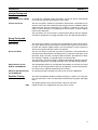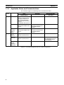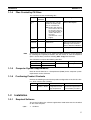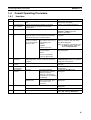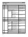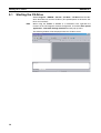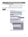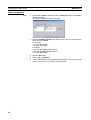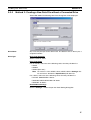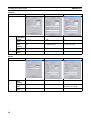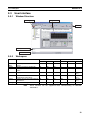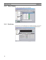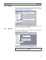
1
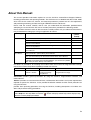
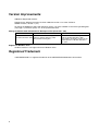
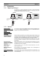
Cat. No. W453-E1-05 SYSMAC CXONE-AL@@C-EV2/ CXONE-AL@@D-EV2 CX-Drive OPERATION MANUAL CXONE-AL@@C-EV2/ CXONE-AL@@D-EV2 CX-Drive Operation Manual Revised June 2007 iv Notice: OMRON products are manufactured for use according to proper procedures by a qualified operator and only for the purposes described in this manual. The following conventions are used to indicate and classify precautions in this manual. Always heed the information provided with them. Failure to heed precautions can result in injury to people or damage to property. !DANGER Indicates an imminently hazardous situation which, if not avoided, will result in death or serious injury. Additionally, there may be severe property damage. !WARNING Indicates a potentially hazardous situation which, if not avoided, could result in death or serious injury. Additionally, there may be severe property damage. !Caution Indicates a potentially hazardous situation which, if not avoided, may result in minor or moderate injury, or property damage. OMRON Product References All OMRON products are capitalized in this manual. The word “Unit” is also capitalized when it refers to an OMRON product, regardless of whether or not it appears in the proper name of the product. The abbreviation “Ch,” which appears in some displays and on some OMRON products, often means “word” and is abbreviated “Wd” in documentation in this sense. The abbreviation “PLC” means Programmable Controller. “PC” is used, however, in some Programming Device displays to mean Programmable Controller. Visual Aids The following headings appear in the left column of the manual to help you locate different types of information. Note Indicates information of particular interest for efficient and convenient operation of the product. 1,2,3... 1. Indicates lists of one sort or another, such as procedures, checklists, etc. OMRON, 2005 All rights reserved. No part of this publication may be reproduced, stored in a retrieval system, or transmitted, in any form, or by any means, mechanical, electronic, photocopying, recording, or otherwise, without the prior written permission of OMRON. No patent liability is assumed with respect to the use of the information contained herein. Moreover, because OMRON is constantly striving to improve its high-quality products, the information contained in this manual is subject to change without notice. Every precaution has been taken in the preparation of this manual. Nevertheless, OMRON assumes no responsibility for errors or omissions. Neither is any liability assumed for damages resulting from the use of the information contained in this publication. v vi TABLE OF CONTENTS PRECAUTIONS . . . . . . . . . . . . . . . . . . . . . . . . . . . . . . . . . . . xv 1 Intended Audience . . . . . . . . . . . . . . . . . . . . . . . . . . . . . . . . . . . . . . . . . . . . . . . . . . . . . . . . . xvi 2 General Precautions . . . . . . . . . . . . . . . . . . . . . . . . . . . . . . . . . . . . . . . . . . . . . . . . . . . . . . . . xvi 3 Safety Precautions . . . . . . . . . . . . . . . . . . . . . . . . . . . . . . . . . . . . . . . . . . . . . . . . . . . . . . . . . xvi 4 Application Precautions. . . . . . . . . . . . . . . . . . . . . . . . . . . . . . . . . . . . . . . . . . . . . . . . . . . . . xvii SECTION 1 Overview . . . . . . . . . . . . . . . . . . . . . . . . . . . . . . . . . . . . . . . . . 1 1-1 Introduction . . . . . . . . . . . . . . . . . . . . . . . . . . . . . . . . . . . . . . . . . . . . . . . . . . . . . . . . . . . . . . 2 1-2 Installation . . . . . . . . . . . . . . . . . . . . . . . . . . . . . . . . . . . . . . . . . . . . . . . . . . . . . . . . . . . . . . . 5 1-3 System Configuration . . . . . . . . . . . . . . . . . . . . . . . . . . . . . . . . . . . . . . . . . . . . . . . . . . . . . . 7 1-4 Overall Operating Procedure . . . . . . . . . . . . . . . . . . . . . . . . . . . . . . . . . . . . . . . . . . . . . . . . . 11 SECTION 2 Basic Operations . . . . . . . . . . . . . . . . . . . . . . . . . . . . . . . . . . . 13 2-1 Starting the CX-Drive . . . . . . . . . . . . . . . . . . . . . . . . . . . . . . . . . . . . . . . . . . . . . . . . . . . . . . 14 2-2 Creating New Drive Files . . . . . . . . . . . . . . . . . . . . . . . . . . . . . . . . . . . . . . . . . . . . . . . . . . . 15 2-3 User Interface. . . . . . . . . . . . . . . . . . . . . . . . . . . . . . . . . . . . . . . . . . . . . . . . . . . . . . . . . . . . . 23 2-4 Editing Drive Files. . . . . . . . . . . . . . . . . . . . . . . . . . . . . . . . . . . . . . . . . . . . . . . . . . . . . . . . . 29 Revision History . . . . . . . . . . . . . . . . . . . . . . . . . . . . . . . . . . . 35 vii TABLE OF CONTENTS viii About this Manual: This manual provides information required to use the CX-Drive Inverter/Servo Support Software, including specifications and operating methods. The CX-Drive runs on Windows 98, Me, NT 4.0, 2000, XP, or Vista and is used to set, transfer, and compare parameters; perform test runs and adjustment; and performing monitoring and data tracing for OMRON Inverters and Servos. Please read this manual carefully and be sure you understand the information provided before attempting to use the CX-Drive. Be sure to read the precautions provided in the following section. Please read the relevant Inverter or Servo manuals carefully and be sure you understand the information provided before setting up or using an application for a drive. Drive type Inverters Servomotors/ Servo Drives Manual Name Cat. No. (suffixes omitted) SYSDRIVE 3G3JV Compact Simplified Inverters User's Manual SYSDRIVE 3G3MV Multi-function Compact Inverter User's Manual I528-E1 I527-E1 SYSDRIVE RV Series Models 3G3RV High-function General-purpose Inverters User's Manual I532-E1 SYSDRIVE RV Series Models 3G3RV-V1 High-function General-purpose Inverters Setup Manual DeviceNet Communications Unit/Card 3G3MV-PDRT2, 3G3RV-PDRT2 User's Manual SMARTSTEP A Series Servomotors/Servo Drives Models R7M-A@ (Servomotors)/R7D-AP@ (Servo Drives) User's Manual OMNUC W Series Models R88M-W@ (AC Servomotors)/Models R88DWT@ (AC Servo Drives) AC Servomotors/Servo Drives User's Manual I549-E1 OMNUC W Series AC Servomotors/Servo Drives with Built-in MECHATROLINK-II Communications Models R88M-W@ (AC Servomotors)/R88DWN@-ML2 (AC Servo Drives) User's Manual I544-E1 I539-E1 I533-E1 I531-E1 For details on procedures for installing the CX-Drive from the CX-One FA Integrated Tool Package, refer to the CX-One Setup Manual (W463) provided with CX-One. Cat. No. W463 Model CXONE-AL@@CEV2/AL@@D-EV2 Name Contents CX-One Ver. 2.1 FA Inte- Installation and overview of CX-One FA grated Tool Package Integrated Tool Package. Setup Manual Precautions provides general precautions for using the CX-Drive, Programmable Controller, and related devices. Section 1 provides an overview of the CX-Drive, and describes the functions and system requirements required to operate the CX-Drive. It also provided installation methods and the overall procedure for using the CX-Drive. provides basic operating procedures for using the CX-Drive, including descriptions of CX-Drive windows and parameter setting procedures. Also refer to the CX-Drive Online Help for operating procedures and functions. Select Help from the Help Menu or click the Button to display context help, which displays help about the currently displayed window. ix Version Improvements Addition of Supported Inverters Support for the following Inverters has been added for version 1.12 of the CX-Drive: 3G3RV Inverters, Version 1 (-V1) To specify the 3G3RV-V1 offline with CX-Drive version 1.3, select "3G3RV" in the Drive Type dialog box (see page 17) and then specify "V1" in the specification field. Change to Relative Path Information for Workspace Files (Extension .sdw) Item Ver. 1.12 Workspace files Link information is held using absolute (file name extension .sdw) paths for all drive data files (.sdd). This prevents moving files. Ver. 1.3 Link information is held using relative paths for all drive data files (.sdd). This enables moving files as long as the relative position of all drive data files is the same. Support for Windows Vista CX-Drive version 1.4 or higher will run on Windows Vista. Registered Trademark • MECHATROLINK is a registered trademark of the MECHATROLINK Members Association. x Read and Understand this Manual Please read and understand this manual before using the product. Please consult your OMRON representative if you have any questions or comments. Warranty and Limitations of Liability WARRANTY OMRON's exclusive warranty is that the products are free from defects in materials and workmanship for a period of one year (or other period if specified) from date of sale by OMRON. OMRON MAKES NO WARRANTY OR REPRESENTATION, EXPRESS OR IMPLIED, REGARDING NONINFRINGEMENT, MERCHANTABILITY, OR FITNESS FOR PARTICULAR PURPOSE OF THE PRODUCTS. ANY BUYER OR USER ACKNOWLEDGES THAT THE BUYER OR USER ALONE HAS DETERMINED THAT THE PRODUCTS WILL SUITABLY MEET THE REQUIREMENTS OF THEIR INTENDED USE. OMRON DISCLAIMS ALL OTHER WARRANTIES, EXPRESS OR IMPLIED. LIMITATIONS OF LIABILITY OMRON SHALL NOT BE RESPONSIBLE FOR SPECIAL, INDIRECT, OR CONSEQUENTIAL DAMAGES, LOSS OF PROFITS OR COMMERCIAL LOSS IN ANY WAY CONNECTED WITH THE PRODUCTS, WHETHER SUCH CLAIM IS BASED ON CONTRACT, WARRANTY, NEGLIGENCE, OR STRICT LIABILITY. In no event shall the responsibility of OMRON for any act exceed the individual price of the product on which liability is asserted. IN NO EVENT SHALL OMRON BE RESPONSIBLE FOR WARRANTY, REPAIR, OR OTHER CLAIMS REGARDING THE PRODUCTS UNLESS OMRON'S ANALYSIS CONFIRMS THAT THE PRODUCTS WERE PROPERLY HANDLED, STORED, INSTALLED, AND MAINTAINED AND NOT SUBJECT TO CONTAMINATION, ABUSE, MISUSE, OR INAPPROPRIATE MODIFICATION OR REPAIR. xi Application Considerations SUITABILITY FOR USE OMRON shall not be responsible for conformity with any standards, codes, or regulations that apply to the combination of products in the customer's application or use of the products. At the customer's request, OMRON will provide applicable third party certification documents identifying ratings and limitations of use that apply to the products. This information by itself is not sufficient for a complete determination of the suitability of the products in combination with the end product, machine, system, or other application or use. The following are some examples of applications for which particular attention must be given. This is not intended to be an exhaustive list of all possible uses of the products, nor is it intended to imply that the uses listed may be suitable for the products: • Outdoor use, uses involving potential chemical contamination or electrical interference, or conditions or uses not described in this manual. • Nuclear energy control systems, combustion systems, railroad systems, aviation systems, medical equipment, amusement machines, vehicles, safety equipment, and installations subject to separate industry or government regulations. • Systems, machines, and equipment that could present a risk to life or property. Please know and observe all prohibitions of use applicable to the products. NEVER USE THE PRODUCTS FOR AN APPLICATION INVOLVING SERIOUS RISK TO LIFE OR PROPERTY WITHOUT ENSURING THAT THE SYSTEM AS A WHOLE HAS BEEN DESIGNED TO ADDRESS THE RISKS, AND THAT THE OMRON PRODUCTS ARE PROPERLY RATED AND INSTALLED FOR THE INTENDED USE WITHIN THE OVERALL EQUIPMENT OR SYSTEM. PROGRAMMABLE PRODUCTS OMRON shall not be responsible for the user's programming of a programmable product, or any consequence thereof. xii Disclaimers CHANGE IN SPECIFICATIONS Product specifications and accessories may be changed at any time based on improvements and other reasons. It is our practice to change model numbers when published ratings or features are changed, or when significant construction changes are made. However, some specifications of the products may be changed without any notice. When in doubt, special model numbers may be assigned to fix or establish key specifications for your application on your request. Please consult with your OMRON representative at any time to confirm actual specifications of purchased products. DIMENSIONS AND WEIGHTS Dimensions and weights are nominal and are not to be used for manufacturing purposes, even when tolerances are shown. PERFORMANCE DATA Performance data given in this manual is provided as a guide for the user in determining suitability and does not constitute a warranty. It may represent the result of OMRON's test conditions, and the users must correlate it to actual application requirements. Actual performance is subject to the OMRON Warranty and Limitations of Liability. ERRORS AND OMISSIONS The information in this manual has been carefully checked and is believed to be accurate; however, no responsibility is assumed for clerical, typographical, or proofreading errors, or omissions. xiii xiv PRECAUTIONS This section provides general precautions for using the CX-Drive. The information contained in this section is important for the safe and reliable application of the CX-Drive. You must read this section and understand the information contained before attempting to install or use the CX-Drive. 1 2 3 4 Intended Audience . . . . . . . . . . . . . . . . . . . . . . . . . . . . . . . . . . . . . . . . . . . . . General Precautions . . . . . . . . . . . . . . . . . . . . . . . . . . . . . . . . . . . . . . . . . . . . Safety Precautions. . . . . . . . . . . . . . . . . . . . . . . . . . . . . . . . . . . . . . . . . . . . . . Application Precautions . . . . . . . . . . . . . . . . . . . . . . . . . . . . . . . . . . . . . . . . . xvi xvi xvi xvii xv 1 Intended Audience 1 Intended Audience This manual is intended for the following personnel, who must also have knowledge of electrical systems (an electrical engineer or the equivalent). • Personnel in charge of installing FA systems. • Personnel in charge of designing FA systems. • Personnel in charge of managing FA systems and facilities. 2 General Precautions The user must operate the product according to the performance specifications described in the operation manuals. Before using the product under conditions which are not described in the manual or applying the product to nuclear control systems, railroad systems, aviation systems, vehicles, combustion systems, medical equipment, amusement machines, safety equipment, and other systems, machines, and equipment that may have a serious influence on lives and property if used improperly, consult your OMRON representative. Make sure that the ratings and performance characteristics of the product are sufficient for the systems, machines, and equipment, and be sure to provide the systems, machines, and equipment with double safety mechanisms. This manual provides information for programming and operating the Unit. Be sure to read this manual before attempting to use the Unit and keep this manual close at hand for reference during operation. !WARNING It is extremely important that the CX-Drive and related devices be used for the specified purpose and under the specified conditions, especially in applications that can directly or indirectly affect human life. You must consult with your OMRON representative before applying CX-Drive and related devices to the above-mentioned applications. 3 Safety Precautions !Caution It may become impossible to stop motor rotation if serial communications fail during test runs. Always provide an external hardware means of stopping the motor. !Caution Confirm safety at the destination node before transferring parameters or other data to another node from the CX-Drive. Doing either of these without confirming safety may result in injury. !Caution Always confirm the axis number carefully before starting operation from the CX-Drive. !Caution The CS1W-CIF31 Serial Conversion Cable cannot be used to connect a computer running the CX-Drive to the 3G3MV. (See the following note.). Note USB-Serial Conversion Cables That Can Be Used For 3G3JV- and 3G3RV-series Inverters: CS1W-CIF31 USB-Serial Conversion Cable. (The commercially available products listed below can also be used.) xvi 4 Application Precautions For 3G3MV-series Inverters: The CS1W-CIF31 cannot be used. Use the commercially available products listed below. Commercially Available USB-Serial Conversion Cables BHS-US01/GP manufactured by Buffalo USB-CVRS9 manufactured by Sanwa The commercially available USB-serial converters have been successfully tested for OMRON Inverters but operation may be unstable in some operating environments (mainly depending on the ambient temperature, humidity, and noise). The functions, performance, and reliability of these converters may not be as specified under all possible conditions. Check the warranty information from the manufacturer. 4 Application Precautions Observe the following precautions when using the CX-Drive. • Confirm that set parameters operate properly before using them in actual applications. • Do not turn OFF the power to the Servo Drive while writing to flash memory. In the worst case, doing so may damage the flash memory. • After replacing an Inverter or Servo Drive, restart operation only after saving the required parameters in the new Inverter or Servo Drive. • Confirm that no adverse effect will occur in the system before attempting any of the following. Not doing so may result in an unexpected operation. • Changing the operating mode of the PLC (including changing the Startup Mode) • Changing parameter settings • Automatically downloading parameters (This function is enable by selecting the Autodownload when a parameter is updated Option on the Online Options Tab Page in the window that appears when Tools - Options is selected from the menu bar.) • Do not turn OFF the power to the computer while installing or uninstalling the CX-Drive. Doing so may result in corrupted data in the computer. • The multi-turn counter and alarms will be set in the absolute serial encoder if the absolute encoder setting function is performed. If the absolute encoder’s multi-turn counter is reset to zero, the coordinate system of the mechanical system will change from what it was previously. Be sure that the encoder is set correctly before resetting the mechanical system to the zero point. xvii Application Precautions xviii 4 SECTION 1 Overview This section provides an overview of the CX-Drive, and describes the functions and system requirements required to operate the CX-Drive. It also provided installation methods and the overall procedure for using the CX-Drive. 1-1 Introduction . . . . . . . . . . . . . . . . . . . . . . . . . . . . . . . . . . . . . . . . . . . . . . . . . . . 2 1-2 Installation. . . . . . . . . . . . . . . . . . . . . . . . . . . . . . . . . . . . . . . . . . . . . . . . . . . . 5 1-3 System Configuration . . . . . . . . . . . . . . . . . . . . . . . . . . . . . . . . . . . . . . . . . . . 7 1-4 Overall Operating Procedure. . . . . . . . . . . . . . . . . . . . . . . . . . . . . . . . . . . . . . 11 1 Section 1-1 Introduction 1-1 1-1-1 Introduction What Is the CX-Drive? The CX-Drive is a software application that enables 1) setting, downloading, uploading, and comparing parameters, 2) test runs and tuning, and 3) monitoring and data tracing for Inverters and Servos. Inverters CX-Drive CX-Drive Setting parameters, test runs, and tuning Monitoring/tracing Inverter 1-1-2 Servos Setting parameters, test runs, and tuning Monitoring/tracing Servo Features Supports Most OMRON Inverters and Servos The CX-Drive can be used with OMRON's 3G3JV, 3G3MV, and 3G3RV Inverters, as well as OMRON's SMARTSTEP, W-series, and MECHATROLINK-IIcompliant (see note) W-series Servo Drives. Wide Range of Parameter Editing Functions Easy and Dependable Parameter Editing for Inverters and Servos Inverter and Servo parameters can be edited using parameter numbers or by category. Parameter editing tables show parameter ID numbers, descriptions, units, default values, and ranges in the same way as in the Servo manuals. Parameters can be set using pull-down menus or by typing in settings. Parameter settings can be easily reviewed because setting status (e.g., modified, warning, default, or disabled) is shown for each parameter to avoid setting mistakes. Easily Check Drive Parameters and Upload/ Download Only Selected Parameters When connected online, you can easily display drive parameters by using a comparison function. Also, the selected parameters can be downloaded to or uploaded from the drive as required. Edit Parameters in Graphic Form Inverter parameters, such as V/F profiles and jump frequencies, can be displayed in graphic charts. Display Parameters in Diagrams Drive parameters can be displayed in diagrams, such as PID diagrams or position/speed/torque block diagrams. Automatically Detect Drives The connected drives can be detected automatically and displayed in a list without setting model numbers or connection types. Just select a drive to add it to the Workspace. 2 Section 1-1 Introduction Inverter Tuning and Test Runs Auto-tuning for the 3G3RV Just enter the specified motor parameters and let the Servo automatically tune itself to match the characteristics of the motor. Inverter Test Runs The test run options enable the acceleration, deceleration, and frequency references of the motor to be determined for testing purposes. Additional options allow the motor to be run continuously or cycled for 'n' number of cycles. Forward or reverse operation and stopping are also possible, and the feedback input can be displayed. The parameters can be set either by entering them directly into the appropriate fields or graphically by dragging handles in the Test Run Setup Diagram. Servo Tuning and Test Runs Auto-tuning The auto-tuning function calculates the load moment of inertia during operation of the Servo and sets parameters to achieve Servo gains that are consistent with the machine rigidity settings. These parameters can be saved in the Servo and used the next time power is turned ON. Servo Test Runs The test run options enable the jog speed, acceleration, and deceleration of the motor to be determined for testing purposes. Continuous operation, cyclic operation, origin searches, turning the Servo ON/OFF, forward/reverse direction selection, stopping, and speed display are also possible. The parameters can be set either by entering them directly into the appropriate fields or graphically by dragging handles in the Test Run Setup Diagram. Adjust Offsets for the R7D-AP and R88D-WT The speed/torque offset can be adjusted automatically or manually, the offset and gain of the analog monitor output can be adjusted, and the current detection offset can be adjusted automatically or manually. Absolute Encoder Setting for the R88D-WT An absolute encoder and multi-turn limit can be set for the R88D-WT. Realtime Tracing The Real Time Monitor Window enables monitoring a specific set of parameters. The parameter values are displayed simultaneously in graphic and digital forms. The graphic display shows the parameter values per unit time. Note Online functions are supported for only one axis at a time. 3 Section 1-1 Introduction 1-1-3 Applicable Drives and Communications The CX-Drive supports the following drives and communications. Drive type Series Inverters 3G3JV MECHATROLINK-II (See note.) Supported. RS-232C Communications Unit (3G3JV-PSI232JC) or RS-422/485 Communications Unit (3G3JV-PSI485J) required. Uses Modbus-RTU protocol. Supported. RS-422A/485: Modbus-RTU protocol --- --- Supported. DeviceNet Communications Unit (3G3MV-PDRT2) required. --- 3G3RV (including version-1 models) Supported. RS-422A/485: Modbus-RTU protocol Supported. DeviceNet Communications Unit (3G3RV-PDRT2) required. --- SMARTSTEP A Series (R7D-AP) Supported. RS-232C: Special protocol --- --- W Series (R88D-WT) Supported. RS-232C: Special protocol --- W Series with MECHATROLINK-II (R88D-WN) --- --- Supported. MECHATROLINK-II Interface Unit (JUSP-NS115/FNYNS115) required. Supported. 3G3MV Servos Communications DeviceNet Serial communications Refer to 1-3 System Configuration for the system configuration. 4 Section 1-2 Installation 1-1-4 Files Created by CX-Drive The CX-Drive creates the following files. File type Workspace file Note File name extension .sdw Contents Saving method Contains the tree for all File - Save Workspace or related drive files. This file Save as Workspace... contains the relative path name for each data file. Note Relative path information is held, so files can be moved as long as the relative position of all drive data files is the same (CX-Drive Ver. 1.3 or higher). Drive file .sdd Monitor .sdm review file Each drive file Data of the Real Time Trace or Data Trace. File - Save or Save As... Select the Save to File Option on the Review Set-up Tab Page in the Real Time Trace or Data Trace Window. Text file for drive file Each drive file File - Export .csv or .txt Consecutive parameters can be exported to Microsoft Excel via the clipboard by selecting the required parameters with the mouse or from the keyboard (Shift + Cursor Keys) and then selecting Edit - Copy from the menu. The CX-Drive can import the following data files. File type File name extension Text file .txt WMON data file .usr 1-1-5 Contents Drive file Saving method File - Import Computer System Requirements Refer to the CX-One Ver. 2.1 Setup Manual (W463) for the computer system requirements for the CX-Drive. 1-1-6 Confirming Product Contents Refer to the following manual for the product configuration of the CX-One Ver. 2.1, which contains the CX-Drive. Cat. No. W463 1-2 1-2-1 Model number CXONE-AL@@CEV2/AL@@D-EV2 Manual name Contents CX-One Ver. 2.1 FA Integrated Tool Package Setup Manual Provides an overview of the CX-One FA Integrated Tool and installation procedures. Installation Required Software To use the CX-Drive, the software applications listed below must be installed on the same computer. 1,2,3... 1. CX-Drive 5 Section 1-2 Installation 2. Communications driver: CX-Server (including CX-Server Driver Management Tool) CX-Drive Availability The CX-Drive must be installed from the CX-One Package. Refer to the following manual for installation procedures for the CX-One Package. Cat. No. W463 6 Model number CXONE-AL@@CEV2/AL@@D-EV2 Manual name CX-One Ver. 2.1 FA Integrated Tool Package Setup Manual Contents Provides an overview of the CX-One FA Integrated Tool and installation procedures. Section 1-3 System Configuration 1-3 1-3-1 System Configuration Inverter Connection Connection type Direct serial connection Connection name Direct PLC Serial Communications Board/ Unit connection Via PLC (SCU/SCB) Configuration CX-Drive CX-Drive Peripheral port or RS-232C port Detach Digital Operator. RS-232C RS-232C Modbus-RTU Inverter Computer-Inverter Connecting Cable (3G3IV-PWV103) (D-Sub 9-pin to Inverter Digital Operator connector) Required devices 3G3JV Digital Operator connector 3G3IV-PWV103 Computer-Inverter Connecting Cable and 3G3JV-PSI232JC RS-232C Communications Unit 3G3MV 3G3IV-PWV103 Computer-Inverter Connecting Cable Remove the Digital Operator from the Inverter and connect the cable to the Digital Operator connector. 3G3RV 3G3IV-PWV103 (includ- Computer-Inverter ing ver- Connecting Cable sion-1 models) For Peripheral Port: CS1W-CN226 (2 m) or CS1W-CN626 (6 m) For RS-232C Port: XW2Z-200S-CV (2 m) or XW2Z-500S-CV (5 m) Or via network 3G3JV-PSI485J RS-422/485 Communications Unit RS-422/485 communications are built into the Inverter. RS-422/485 communications are built into the Inverter. Connection type PLC DeviceNet connection (via DeviceNet Unit) Connection name Configurations Via PLC (DeviceNet) CS/CJ-serial Serial Communications Board/ Unit Ver.1.2 or later CS/CJ-series PLC RS-422A/485 Modbus-RTU Inverter CS/CJ-series Serial Communications Board/Unit Ver. 1.2 or later. Note The Serial Gateway Mode is used as the serial communications mode for the RS422A/485 port. CX-Drive Peripheral port Or RS-232C port CS/CJ-series DeviceNet Unit CS/CJ-series PLC For Peripheral Port: CS1W-CN226 (2 m) or CS1W-CN626 (6 m) For RS-232C Port: XW2Z-200S-CV (2 m) or XW2Z-500S-CV (5 m) Or via network Required devices DeviceNet Inverter 3G3JV --3G3MV 3G3MV-PDRT2 DeviceNet Communications Unit 3G3RV 3G3RV-PDRT2 DeviceNet Communications Card 7 Section 1-3 System Configuration 1-3-2 Servo Connection Connection type Direct serial connection Connection name Configuration Direct PLC Serial Communications Board/Unit connection Via PLC (SCU/SCB) • Without Servo Relay Unit (operated only with CXDrive) CX-Drive CX-Drive Peripheral port Or RS-232C port RS-232C Servo R7D-AP: R7A-CCA002P2 R88D-WT: R88A-CCW002P2 Connector on Servo: CN3 CS/CJ-series Serial Communications Board/Unit Ver. 1.2 or later RS-232C CS/CJ-series PLC For Peripheral Port: CS1W-CN226 (2 m) or CS1W-CN626 (6 m) For RS-232C Port: XW2Z-200S-CV (2 m) or XW2Z-500S-CV (5 m) Or via network RS-232C adaptor (commercially available) RS-232C Servo Connector on Servo: CN3 R7D-AP: R7A-CCA002P2 R88D-W: R88A-CCW002P2 • With Servo Relay Unit to Control Servo CX-Drive Peripheral port Or RS-232C port CS/CJ-series Serial Communications Board/Unit Ver. 1.2 or later RS-232C CS/CJ-series PLC For Peripheral Port: CS1W-CN226 (2 m) CS1W-CN626 (6 m) For RS-232C Port: XW2Z-200S-CV (2 m) XW2Z-500S-CV (5 m) Or via network RS-422A/485 XW2Z-@@@J-CJ Serial Communications Unit/Board Connecting Cable XW2B-40J6-4A Servo Relay Unit Servo · SMARTSTEP A-series Connecting Cable: XW2Z-@@@J-B7 · W-series Connecting Cable: XW2Z-@@@J-B8 8 Connector on Servo: · SMARTSTEP A Series: CN1 · W Series For Support Software: CN3 For Servo Control: CN1 Section 1-3 System Configuration Connection type Connection name Required devices Direct serial connection Direct SMARTSTEP R7A-CCA002P2 (2 m) A Series (R7D-AP) W Series (R88D-WT) R88A-CCW002P2 (2 m) W Series --with MECHATROLINK-II (R88D-WN) PLC Serial Communications Board/Unit connection Via PLC (SCU/SCB) • R7A-CCA002P2 (2 m) + RS232C 9-pin adaptor Or • XW2Z-@@@J-CJ Serial Communications Unit/Board Connecting Cable + XW2B40J6-4A Servo Relay Unit + XW2Z-@@@J-B7 SMARTSTEP A-series Connecting Cable • R88A-CCW002P2 (2 m) + RS-232C 9-pin adaptor Or • XW2Z-@@@J-CJ Serial Communications Unit/Board Connecting Cable + XW2B40J6-4A Servo Relay Unit + XW2Z-@@@J-B8 SMARTSTEP A-series Connecting Cable CS/CJ-series Serial Communications Board/Unit Ver. 1.2 or later Note The Serial Gateway Mode is used as the serial communications mode for the RS-232C port. --- Connection type PLC (MCH/NCF Unit) MECHATROLINK-II connection Connection name Via PLC (MCH/MECHATROLINK-II) Via PLC (NCF/MECHATROLINK-II) Configuration CX-Drive Peripheral port Or RS-232C port RS-232C CS/CJ-series MECHATROLINK-II Motion Control Unit or Position Control Unit CS/CJ-series PLC For Peripheral Port: CS1W-CN226 (2 m) or CS1W-CN22626 (6 m) For RS-232C Port: XW2Z-200S-CV (2 m) XW2Z-500S-CV (5 m) Or via network Required devices MECHATROLINK-II Servo Servo SMARTSTEP --A Series: R7D-AP W Series: MECHATROLINK-II Cable R88D-WT MECHATROLINK-II Interface Unit (JUSP-NS115 or FNYNS115) W Series MECHATROLINK-II Cable with MECHATROLINK-II: R88D-WN !Caution The CS1W-CIF31 Serial Conversion Cable cannot be used to connect a computer running the CX-Drive to the 3G3MV. (See the following note.). 9 Section 1-3 System Configuration Note USB-Serial Conversion Cables That Can Be Used For 3G3JV- and 3G3RV-series Inverters: CS1W-CIF31 USB-Serial Conversion Cable. (The commercially available products listed below can also be used.) For 3G3MV-series Inverters: The CS1W-CIF31 cannot be used. Use the commercially available products listed below. Commercially Available USB-Serial Conversion Cables BHS-US01/GP manufactured by Buffalo USB-CVRS9 manufactured by Sanwa The commercially available USB-serial converters have been successfully tested for OMRON Inverters but operation may be unstable in some operating environments (mainly depending on the ambient temperature, humidity, and noise). The functions, performance, and reliability of these converters may not be as specified under all possible conditions. Check the warranty information from the manufacturer. 10 Section 1-4 Overall Operating Procedure 1-4 Overall Operating Procedure 1-4-1 Inverters No. 1 Step Install the software. Install the CX-Server and CX-Drive from the CXOne. Operations Refer to the CX-One Ver. 2.1 Setup Manual (Cat. No. W463). 2 Connect the drive to the computer. Refer to 1-3 System Configuration. 3 4 Connect the CX-Drive (computer) to the drive (Inverter or Servo) using one of the system configurations. Start the CX-Drive. --- Create a new drive Method 1 file. Detect the drives connected online automatically and create drive file for the desired drive. Method 2 Select Inverter as the drive Create a new drive type and then select one of file on the computer the following series. without a drive. • 3G3JV • 3G3MV • 3G3RV (See note.) Select Program - OMRON - CX-One CX-Drive - CX-Drive from the Windows Start Menu. Select File - Autodetect from the menu bar. Select File - New from the menu bar and then select the drive type in the New Drive Dialog Box. Note For version 1 of the 3G3RV, click the Settings Button and select -V1 for the Specification. Select one of the following connection types. • Direct • Via PLC (SCU/SCB) • Via PLC (DeviceNet) Select the connection type in the New Drive Dialog Box. 5 Edit the parameters. Edit the parameters for the Inverter. Edit parameters in numeric order or by functional category. In the Workspace, double-click Parameter edit and then the required categories in the drive file. 6 Connect online to the drive. --- Select Drive - Work Online from the menu bar. 7 Transfer and verify the parameters. Tune and test operation. --- Select Drive - Transfer - To drive from the menu bar. Double-click Test Run in the Workspace. 8 Test Run Perform the following: Forward/reverse operation, stopping, frequency references, acceleration/ deceleration, S-curve display, and dwelling. Auto Tune (3G3RV only) 9 Monitor operation. Enter the motor parameters, perform auto-tuning, and then save the new parameters. Perform a Real Time Trace. 10 Save the data. Check the status. Save the Workspace and/or the drive file Double-click Auto Tune in the Workspace. Double-click Real Time Trace in the Workspace. Double-click Status in the Workspace. Select File - Save Workspace, or select File - Save as Workspace… 11 Section 1-4 Overall Operating Procedure 1-4-2 No. 1 2 3 4 5 6 7 8 Servos Install the software. Connect the drive to the computer. Start the CX-Drive. Step Install the CX-Server and CX-Drive from the CX-One. Connect the CX-Drive (computer) to the drive (Inverter or Servo) using one of the system configurations. --- Create a new drive Method 1 file. Detect the drives connected online automatically and create drive file for the desired drive. Method 2 Select Servo as in the drive type Create a new drive and then select one of the file on the computer following series. without a drive. • R7D-AP (SMARTSTEP A Series) • R88D-WN (MECHATROLINK-IIcompliant W Series) • R88D-WT (W Series) Select one of the following connection types. • Direct • Via PLC (SCU/SCB) • Via PLC (MCH/MLII) • Via PLC (NCF/MLII) Edit the Edit the parameters for the Servo. Edit parameters in parameters. numeric order or by functional category. Connect online to the drive. Transfer and verify the parameters. Tune and test operation. ----Test Run (R7D-AP or R88D-WT only) Auto Tune (R7D-AP or R88D-WT only) Offset (R7D-AP or R88D-WT only) 9 Monitor operation. 10 Save the data. 12 Perform the following: Jogging, origin searches, forward/reverse operation, stopping, and speed control. The auto-tuning function calculates the load moment of inertia during Servo operation and sets parameters to achieve Servo gains that are consistent with the machine rigidity settings. The speed/torque offset can be adjusted automatically or manually, the offset and gain of the analog monitor output can be adjusted, and the current detection offset can be adjusted automatically or manually. An absolute encoder and multiturn limit can be set. Absolute Encoder Setting (R88D-WT only) Perform a Real Time Trace (R7D-AP or R88D-WT only). Check the status. Save the Workspace and/or the drive file. Operations Refer to the CX-One Ver. 2.1 Setup Manual (Cat. No. W463). Refer to 1-3 System Configuration. Select Program - OMRON - CXOne - CX-Drive - CX-Drive from the Windows Start Menu. Select File - Autodetect from the menu bar. Select File - New from the menu bar and then select the drive type in the New Drive Dialog Box. Select the connection type in the New Drive Dialog Box. In the Workspace, double-click Parameter edit and then the required categories in the drive file. Select Drive - Work Online from the menu bar. Select Drive - Transfer - To drive from the menu bar. Double-click Test Run in the Workspace. Double-click Auto Tune in the Workspace. Double-click Offset in the Workspace. Double-click Absolute Encoder in the Workspace. Double-click Real Time Trace in the Workspace. Double-click Status in the Workspace. Select File - Save Workspace, or select File - Save as Workspace… SECTION 2 Basic Operations This section provides basic operating procedures for using the CX-Drive, including descriptions of CX-Drive windows and parameter setting procedures. 2-1 Starting the CX-Drive . . . . . . . . . . . . . . . . . . . . . . . . . . . . . . . . . . . . . . . . . . . 14 2-2 Creating New Drive Files . . . . . . . . . . . . . . . . . . . . . . . . . . . . . . . . . . . . . . . . 15 2-3 User Interface . . . . . . . . . . . . . . . . . . . . . . . . . . . . . . . . . . . . . . . . . . . . . . . . . 23 2-4 Editing Drive Files . . . . . . . . . . . . . . . . . . . . . . . . . . . . . . . . . . . . . . . . . . . . . 29 13 Section 2-1 Starting the CX-Drive 2-1 Starting the CX-Drive Select Program - OMRON - CX-One - CX-Drive - CX-Drive from the Windows Start Menu to start the CX-Drive. (The path depends on where the CXDrive was installed.) Note When using the 3G3MV or 3G3RV as a DeviceNet slave, right-click the Inverter on the CX-Integrator network configuration, and select Start special application - Start with Settings Inherited from the pop-up menu. The following window will be displayed when the CX-Drive starts. 14 Section 2-2 Creating New Drive Files 2-2 Creating New Drive Files There are two methods to create a new drive file in the Workspace. Method 1: Go online and automatically detect the connected drives to create the drive file. Method 2: Create a new data file without using a connected drive. 2-2-1 Method 1: Automatically Detecting the Connected Drives Serial Direct Connection 1,2,3... 1. Select File - Autodetect. The Autodetect Dialog Box will be displayed and automatic detection will start. The detected drives will be displayed The detected drives are displayed in a list. 2. Select the drive from the list to create a new drive file in the Workspace. Automatically registered in the Workspace. 15 Section 2-2 Creating New Drive Files Other Connections 1,2,3... 1. Select Tool - Options. Alternately click the Settings Button in the Autodetection Dialog Box The Options Dialog Box will be displayed. 2. Click the Autodetect Options Tab and then select one or more connection types other than Direct. For Inverters: • Via PLC (DeviceNet) • Via PLC (SCU/SCB) For Servos: • Via PLC (MCH/MECHATROLINK II) • Via PLC (NCF/MECHATROLINK II) • Via PLC (SCU/SCB) 3. Click the OK Button. 4. Select File - Autodetect. 5. Click the Start Button in the Autodetection Dialog Box. The rest of the procedure is the same as for a direct serial connection. 16 Section 2-2 Creating New Drive Files 2-2-2 Method 2: Creating a New Data File without a Connected Drive Select File - New. The following New Drive Dialog Box will be displayed. Drive Name Any name may be input for the drive name. The default name is “Drive” plus a sequential number. Drive Type Drive Type Selection Select Inverter or Servo. Drive Type Name For an Inverter, select one of the following series from the pull-down list. • 3G3JV • 3G3MV • 3G3RV (See note.) Note For version 1 of the 3G3RV, select 3G3RV, click the Settings Button and select -V1 from the Specification pull-down list. For a Servo, select one of the following series from the pull-down list. • R7D-AP: SMARTSTEP A Series • R88D-WN: MECHATROLINK-II W Series • R88D-WT: W Series Detailed Drive Settings Click the Settings… Button to open the Detail Setting Dialog Box. 17 Section 2-2 Creating New Drive Files Inverters Inverter Series Dialog box 3G3JV Drive Type Installation A Type/Option Options 3G3MV 3G3RV A, X A, B, X 2, 4, B 2, 4 Voltage Class 1, 2, 4, B Maximum Motor Capacity 001, 002, 004, 007, 015, 022, 001, 002, 004, 007, 015, 022, 004, 007, 015, 022, 037, 055, 037 037, 040, 055, 075 075, 110, 150, 185 Specifications --- --- None or V1 Option Board --- 3G3MV-PDRT2 3G3RV-PDRT2 Servos Servo Series Dialog box Drive Type Maximum Motor Capacity Voltage Class Specifications 18 R7D-AP R88D-WN R88D-WT A3 (30 W) to 08 (750 W) A5 (50 W) to 30 (3 kW) A3 (30 W) to 150 (15 kW) H (200 V), L (100 V) H (200 V), L (100 V) H (200 V), HF (400 V), HH (200 V), HL (150 V) --- ML2 --- Section 2-2 Creating New Drive Files Connection Type Connection Type Selection Select one of the following connection types for the Connection Type. Inverters Connection type Selection 3G3JV Direct Serial Connection Inverter Series 3G3MV 3G3RV Direct Supported. Supported. Supported. Via PLC (SCU/SCB) Supported. Supported. Supported. Via PLC (DeviceNet) Not Supported. Supported. supported. CX-Drive RS-232C Modbus-RTU Inverter Connector for Digital Operator PLC (Serial Communications Board/Unit) Connection CX-Drive CS/CJ-series Serial Communications Board/Unit Unit Ver. 1.2 or higher RS-232C (Serial Gateway: Converts from FINS to Modbus.) CS/CJ-series PLC RS-422A/485 Modbus-RTU Inverter PLC (DeviceNet Unit) Connection CX-Drive CS/CJ-series DeviceNet Unit CS/CJ-series PLC RS-232C DeviceNet Inverter 19 Section 2-2 Creating New Drive Files Servos Connection type Selection R7D-AP Direct Serial Connection Servo Series R88D-WN R88D-WT Direct Supported. Not supported. Supported. Via PLC (SCU/SCB) Supported. Not supported. Supported. Via PLC Not (MCH/ supported. MECHATROLINK-II) Supported. Supported with JUSPNS115 (FNYNS115). Via PLC Not (NCF/ supported. MECHATROLINK-II) Supported. Supported with JUSPNS115 (FNYNS115). CX-Drive RS-232C Special commands Servo PLC (Serial communications Board/Unit) Connection CX-Drive CS/CJ Serial Communications Board/Unit Unit Ver.1.2 or later CS/CJ Series PLC RS-232C (Serial gateway function: Converts FINS to Internal W commands.) Special commands RS-232C or RS-422A/485 when connected to Servo Relay Unit Servo PLC (MCH Unit) MECHATROLINK-II Connection CS/CJ Series CX-Drive MECHATROLINK-II Motion Control Unit/ Position Control Unit CS/CJ Series PLC RS-232C MECHATROLINK-II Servo Servo PLC (NCF Unit) MECHATROLINK-II Connection 20 Section 2-2 Creating New Drive Files Network Settings Click the Settings... Button to the right of the Connection Type Field. The following dialog box will be displayed. Detailed Settings for Direct Connections Item Dialog box Network Tab Page Drive Tab Page Inverter • Slave Unit Address: 1 to 32 (Modbus-RTU slave address) (See note 1.) • Communications Timeout: 500 to 5,000 ms • Number of retries: 1 to 6 • Port Selection: COM1, COM2, etc. • Baud Rate: 2400, 9600, 19200, or 38400 bits/s • Parity: None, Odd, or Even • Data bits: 7 or 8 • Stop bits: 1 or 2 Servo • Slave Unit Address: 0 to F (Servo Drive communications Unit No.) (See note 2.) • Communications Timeout: 500 to 5,000 ms • Number of retries: 1 to 6 • Port Selection: COM1, COM2, etc. • Baud Rate: 9600 or 19200 bits/s • Parity: None, Odd, or Even • Data bits: 7 or 8 • Stop bits: 1 or 2 Via PLC (SCU/SCB) Connections (Except R88D-WN) Item Dialog box Inverter Servo Network Tab Page Gateway PLC Tab Page • Slave Unit Address: 1 to 32 (Modbus-RTU slave Click the Properties Button to set the PLC (with a address) (See note 1.) Serial Communications Unit/Board) to use as the gateway. • Master Unit Address: 0 to 15 (Unit address for Serial Communications Unit). Or select CS-Series Inner Board Option (Serial Communications Board). • Port Selection: Port 1 or Port 2 • Slave Unit Address: 0 to F (Servo Communications Unit No.) (See note 2.) • Master Unit Address: 0 to 15 (Unit Address for Serial Communications Unit). Or select CS-Series Inner Board Option (Serial Communications Board). • Port Selection: Port 1 or Port 2 21 Creating New Drive Files Section 2-2 Note (1) Modbus-RTU Slave Address Setting: The Modbus-RTU slave address (01 to 32) is set in the following parameter using the Digital Operator on front of the Inverter before connecting the CX-Drive. Inverter Series Parameter No. 3G3JV n70 3G3MV n153 3G3RV H5-01 (2) The Servo Communications Unit No. (0 to F) is set using the following method before connecting the CX-Drive. Servo Series Method R7D-AP Unit number rotary switch on the Servo 3 R88D-WT Change to the Setting Mode using the Servo front panel settings and set the unit number in digit 2 of Pn000. Via PLC (DeviceNet) Connections (3G3MV, 3G3RV) Network Tab Page Gateway PLC Tab Page • Slave Unit Address: 0 to 63 (DeviceNet Click the Properties Button to set the slave address) PLC (with a DeviceNet Unit) to use as the • Master Unit Address: 0 to 15 (DeviceNet gateway. unit number) Via PLC (MCH/MECHATROLINK-II) or Via PLC (NCF/MECHATROLINK-II) (R88D-WN) Network Tab Page • Axis Number: 1 to 32 for MCH or 1 to 16 for NCF • Master Unit Address: 0 to 15 (MCH or NCF unit number) 22 Gateway PLC Tab Page Click the Properties Button to set the PLC (with a MCH or NCF Unit) to use as the gateway. Section 2-3 User Interface 2-3 User Interface 2-3-1 Window Structure Workspace Windows Toolbar Output Window Status bar 2-3-2 Folder Workspace Contents 3G3RV OK R7D-AP OK R88D-WN R88D-WT OK OK OK OK OK --- --- --- --- OK OK --- --- OK OK OK OK OK --- OK Enables realtime traces and other monitoring of online drives. Enables test runs and auto-tuning of OK online drives. OK OK OK --- OK OK OK --- OK (See note.) OK (See note.) OK (See note.) OK OK OK --- Edits the parameters of Inverters or Servos. Displays parameters graphically. Diagrams Displays parameters in block diagrams. Displays online drive status. Monitor Tuning Settings Servos 3G3MV OK Parameter Editor Graphs Status Inverters 3G3JV OK Enables initializing online drives. Note OK OK These functions are not supported when communicating via MECHATROLINK II. 23 Section 2-3 User Interface Inverters Folder Parameter Editor 3G3JV • Initialize • Application • Tuning • Reference • Motor • Terminal • Protection • Operator • Monitor Constants 3G3MV • Initialize • Application • Tuning • Reference • Motor • Options • Terminal • Protection • Operator • Up 2/Down 2 • Monitor Constants 3G3RV • Initialize • Application • Tuning • Reference • Motor • Options • Terminal • Protection • Special Adjustment • Operator • Motor Auto-tuning • Monitor Constants Graphs • Analogue Input 1 • Analogue Output 1 • Jump Frequencies • V/F Profile • Analogue Input 1 • Analogue Input 2 • Analogue Output 1 • Analogue Output 2 • Jump Frequencies • V/F Profile • V/F Profile Motor 2 Diagrams --- • Analogue Output 1 • Frequency Reference Input • Jump Frequencies • Multifunction Analogue Current Input • Multifunction Analogue Voltage Input • V/F Profile • PID Control Loop • PID Target Value • PID Feedback Value Status Monitor • Digital Inputs • Digital Outputs • Inverter Status 1 • Status Signal • Alarms • Real Time Trace • Digital Inputs • Digital Outputs • Inverter Status 1 • Status Signal • Alarms • Real Time Trace • Digital Inputs • Digital Outputs • Inverter Status 1 • Status Signal • Alarms • Real Time Trace Tuning • Test Run • Test Run Settings • Initialize • Initialize • Test Run • Auto-tune • Initialize • Password Authorization 24 • PID Control Loop Section 2-3 User Interface Servos Folder Parameter Editor R7D-AP • Other Constants • Function Selection Constants • Gain Related Constants • Position Related Constants • Speed Related Constants • Torque Related Constants • Sequence Related Constants R88D-WN • Function Selection Constants • Gain Related Constants • Position Related Constants • Speed Related Constants • Torque Related Constants • Sequence Related Constants • Regenerative Resistor Capacity • Motion Parameters • MECHATROLINK-II Constants R88D-WT • Other Constants • Function Selection Constants • Gain Related Constants • Position Related Constants • Speed Related Constants • Torque Related Constants • Sequence Related Constant Diagrams --- --- Status • Input signals • Output signals • Motion Status • Alarms --- • Position Block Diagram • Speed Block Diagram • Torque Block Diagram • Input signals • Output signals • Motion Status • Alarms Monitor • Real Time Trace • Data Trace • Test Run • Auto Tune • Offset --- Tuning Settings • Initialize • Password Authorization • Product Information --- --- • Real Time Trace • Data Trace • Test Run • Auto Tune • Offset • Absolute Encoder • Initialize • Module Detection Clear • Password Authorization • Product Information 25 Section 2-3 User Interface 2-3-3 Menu File Menu Commands Submenu/Command Icon OK Autodetect Detect drives automatically. OK OK Open Opens an existing drive file (.sdd), or monitor review file (.sdm). OK OK Close Open Workspace Closes an open drive file (.sdd). Opens an existing Workspace (.sdw). OK OK OK OK --- Close Workspace Save Workspace Closes the active Workspace (.sdw). Saves the active Workspace (.sdw). OK OK OK OK ----- Save as Workspace OK OK --- OK OK OK OK Save All Saves the active Workspace with a new name (.sdw). Saves an open drive file using its existing file name (.sdd). Saves an open drive file using a specified file name and directory (.sdd). Saves all currently open drive files (.sdd). OK OK Print Prints the current drive file. OK OK Print Preview Displays a print preview of the drive file in OK the active window. Changes printing options, such as marOK gins, include drive information, drive type page heading, etc. OK Page Setup --- OK --- Import Export Imports a file from the specified directory. OK Exports the current drive file to a file in the OK specified directory as a CSV or text file. OK OK ----- Recent file Recent Workspace Opens a recent drive file. Opens a recent Workspace. OK OK OK OK ----- Exit Undo Exits the CX-Drive. Undoes the previous editing operation. OK OK OK OK --- Cut Deletes data from the drive file and places it on the clipboard. Copies data from the drive file and places it on the clipboard. Pastes data from the clipboard into the drive file. Deletes selected data from the drive file. OK OK OK OK OK OK OK OK --- Copy Paste Delete 26 Servo OK Save As View Inverter Creates a new drive file. Save Edit Contents New Select All Find Selects all the data in the drive file. Searches for a specific item in the drive file. OK OK OK OK --- Tool Bars Shows or hides the toolbars (Standard, Modes, Drive, View, and Tools). OK OK --- Status Bar Shows or hides the status bar for the drive OK type name and other information. OK --- Workbook Mode Full Screen Shows the selected windows with tabs. Displays the active view in full screen mode. OK OK OK OK --- Output Shows or hides the output window. OK OK Section 2-3 User Interface Menu View Submenu/Command Workspace Contents Shows or hides the Workspace window. Motor Operation OK Pan Mode Shows or hides the motor operation win- OK dow. Zooms in and out using a rectangle, initial OK setting, etc. Actives the full scroll mode. OK Cursor Mode Actives the cursor mode. OK OK Show Parameter Labels Show Parameter Value Shows or hides parameter labels. Shows or hides parameter values. OK OK OK OK Show Changes Only Displays only parameters with modified values. OK OK Show Differences Only Displays only parameters with values different from the drive. OK OK Show Invalids Only OK Display Format Displays only parameters with invalid val- OK ues. Changes to one of the following display OK formats: Normal, High Low Text, Orange LED, Red LED, Green LED, or Blue LED. OK Change Edits the active drive properties. OK OK Work Online Connects to the drive. OK OK Initialize Initializes the parameters of the drive to the default values. Sets the password for the drive. OK OK OK OK OK Reset Selection Opens the parameter editor view for the OK current drive. Opens the graphical editor containing the OK selected parameter. Resets the currently selected parameters. OK OK Reset All Resets all parameters. OK OK Save To FROM (for Servo via MCH only) Saves the parameters to the flash memory in the Servo via MCH. --- OK Transfer To Drive Downloads the complete parameter set to OK the drive. OK From Drive Uploads the complete parameter set from OK the drive. OK Compare with Drive Uploads the parameters of the drive in the OK Drive Value Column to enabling comparing the parameter set. OK Selection To Drive Downloads the selected parameters to the drive. OK OK OK OK OK OK --- OK --- OK OK OK Zoom Drive Password Protection Parameter Editor Select Parameter Graph Uploads the selected parameters from the drive. Alarms Opens the drive alarm window showing the current alarms and alarm trace. No Module Detection Clear Clears the A.E7 (No module detection) error. Data Trace Configures and activates the Servo data trace function. Selection From Drive Real Time Trace Displays the current values of the selected parameters. Inverter Servo OK OK Icon --- OK OK ----- --- OK --- 27 Section 2-3 User Interface Menu Drive Submenu/Command Test Contents Performs a test run. Inverter Servo OK OK Auto-Tune Executes the auto-tuning function built into the drive. OK OK Set Absolute Encoder Configures a Servomotor absolute encoder. Configures Servo offsets. --- OK --- Adjust Offsets Tools Window Help --- OK --- OK OK OK OK ----- Options Displays product information. Upgrades the database to the latest version. Sets CX-Drive options. OK OK Calculator Displays the Microsoft calculator. OK OK Compare Drives Displays the parameter differences between 2 drive files. OK OK --- Close All Cascade Closes all open windows. Arranges windows as overlapping files. OK OK OK OK ----- Tile Horizontally Arranges windows as horizontal, nonoverlapping tiles. OK OK --- Tile Vertically Arranges windows as vertical, non-overlapping tiles. OK OK --- Arrange Icons Arranges the icons at the bottom of the window. Displays an index to topics on which help is available. Provides contextual help to provide help relating to the active window. Registers your application on the OMRON website. Opens the OMRON Corporate website. OK OK --- OK OK OK OK OK OK --- OK OK --- OK OK Product Information Database Upgrade Help Topics Help Online Registration Omron on the web About CX-Drive 28 Icon Displays the version number of the application. Section 2-4 Editing Drive Files 2-4 Editing Drive Files 1. Use the New Drive Dialog Box to set the drive name, drive type, connection type, and other information, or 2. Use Autodetect to select the target drive. The following window will be displayed. : Inverter Click Click : Servo "Offline" or "online" displayed after the drive name. to display lower folder. at the left of the drive name to display the following tree. 29 Section 2-4 Editing Drive Files 2-4-1 Editing Parameters The parameters for each drive (an Inverter or Servo) can be edited under the parameter numbers. Parameter Editor: Numeric Order Double-click Parameter Editor to open the Parameter Editor Window in numeric order. Select and set each parameter. Double-click. Select or input each parameter value. All parameters displayed in numeric order. Parameter Editor in Functional Categories Double-click the category folder to open the Categorized Parameter Editor Window. Select and set each parameter. Double-click. Select or input each parameter value. Comparing Drive and Parameter Data The comparison operation uploads drive parameters without changing parameter values in the file data. The Parameter Editor Window shows both the drive file and the file data at the same time, and indicates the differences. : Default, : Default but different from the drive, : Not default and different from the drive. : Invalid, 30 : Invalid and different from the drive. : Not default, Section 2-4 Editing Drive Files 2-4-2 Graphs Parameters can be displayed in graphic form for review (for Inverters only). Graphic displayed for specified parameter. Double-click. 2-4-3 Diagrams Parameters can be displayed in block diagrams for relevant parameters. Inverters support PID block diagrams, and Servos support position, speed and torque block diagrams. Block diagram displayed for specified parameter. Double-click. 31 Section 2-4 Editing Drive Files 2-4-4 Status Displays The status of the online drive can be displayed. Double-click. Performs status monitor for the connected drive. 2-4-5 Monitoring Realtime traces can be displayed for the selected parameters of the online drive. Data traces are also possible for the R7D-AP and R88D-WT Servos. Performs realtime trace of the specified parameter. Double-click. 32 Section 2-4 Editing Drive Files 2-4-6 Tuning Test runs can be performed for the online drive. The frequency reference, jog speed, acceleration time, and deceleration time on the graph can be changed by entering values directly or by dragging handles. Drag handles to change parameters. Performs test run for the online drive. Double-click. For Servos, auto-tuning, motor current detect offset adjustments, and absolute multi-turn limit settings are also supported. 2-4-7 Settings The parameters of the online drive can be initialized, and password authorization can be set for some drive models. The parameters in the online drive can be initialized. Double-click. Also refer to the CX-Drive Online Help for operating procedures and functions. Select Help from the Help Menu or click the Button to display context help, which displays help about the currently displayed window. 33 Editing Drive Files 34 Section 2-4 Revision History A manual revision code appears as a suffix to the catalog number on the front cover of the manual. Cat. No. W453-E1-05 Revision code The following table outlines the changes made to the manual during each revision. Page numbers refer to the previous version. Revision code 01 02 Date Revised content November 2005 Original production January 2006 Pages xvi and 9: Caution on the use of the USB serial converter added. 03 April 2006 Caution on the use of the USB serial converter revised and revisions for product version 1 accompanying upgrade to CX-Drive version 1.12 added. 04 July 2006 Corrections accompanying upgrade from CX-Drive version 1.12 to 1.3. (Specifications changed from absolute path information for all drive data files in the workspace (file name extension .sdw) to relative path information.) 05 June 2007 Corrections accompanying upgrade from CX-Drive version 1.3 to 1.4 (Windows Vista). 35 Revision History 36 OMRON Corporation Control Devices Division H.Q. Shiokoji Horikawa, Shimogyo-ku, Kyoto, 600-8530 Japan Tel: (81)75-344-7109/Fax: (81)75-344-7149 Regional Headquarters OMRON EUROPE B.V. Wegalaan 67-69, NL-2132 JD Hoofddorp The Netherlands Tel: (31)2356-81-300/Fax: (31)2356-81-388 OMRON ELECTRONICS LLC One Commerce Drive Schaumburg, IL 60173-5302 U.S.A. Tel: (1) 847-843-7900/Fax: (1) 847-843-7787 OMRON ASIA PACIFIC PTE. LTD. No. 438A Alexandra Road # 05-05/08 (Lobby 2), Alexandra Technopark, Singapore 119967 Tel: (65) 6835-3011/Fax: (65) 6835-2711 OMRON (CHINA) CO., LTD. Room 2211, Bank of China Tower, 200 Yin Cheng Zhong Road, Pu Dong New Area, Shanghai, 200120, China Tel: (86) 21-5037-2222/Fax: (86) 21-5037-2200 Authorized Distributor: Cat. No. W453-E1-05 Note: Specifications subject to change without notice This manual is printed on 100% recycled paper. Printed in Japan