1
LonWorks System Integrator Guide for the Intelli-Fin Boiler Interface Controller
Version LOCH SIG-01
LonWorks System Integrator Guide
for the
Intelli-Fin Boiler Interface Controller
Before Serial # I03H0015780
By Lochinvar Corporation
June 2001
Page 1
LonWorks System Integrator Guide for the Intelli-Fin Boiler Interface Controller
Version LOCH SIG-01
Page 2
LonWorks System Integrator Guide for the Intelli-Fin Boiler Interface Controller
Version LOCH SIG-01
Page 3
TABLE OF CONTENTS
Who should read the System Integrators Guide?.......................................................................................................................... 3
Abbreviations used in this document............................................................................................................................................ 4
Trademarks ................................................................................................................................................................................... 4
References .................................................................................................................................................................................... 4
Benefits of System Integration ..................................................................................................................................................... 5
LonWorks overview ..................................................................................................................................................................... 7
BIC details .................................................................................................................................................................................... 8
One unit .................................................................................................................................................................................... 8
Multiple units for increased capacity ...................................................................................................................................... 12
Intended uses .......................................................................................................................................................................... 13
Network Variables Available to the System Integrator .......................................................................................................... 14
Node Object (nviRequest, nvoStatus, and nciConfigSr)................................................................................................. 14
Data sharing between units and sequencer (nvoSeqShare, nviSeqShare, nvoModBoilrShare, nviModBoilrShare)....... 16
Operating Mode (nvoData.Mode)................................................................................................................................... 17
Time in a given mode (nvoData.ModeTimer) ................................................................................................................ 19
Number of heat stages requested to be turned on (nvoData.HeatStages)........................................................................ 19
Variable frequency drive position (nvoData.VFDPos) ................................................................................................... 19
Bypass valve position (nvoDataBypassPos) ................................................................................................................... 19
Boiler Run Time (nvoIO.BlrTotRtHr) ............................................................................................................................ 20
Temperature reports........................................................................................................................................................ 21
On / Off information ....................................................................................................................................................... 22
Occupancy status ............................................................................................................................................................ 23
Configuration Parameters setting temperatures .............................................................................................................. 24
Control Point Calculation ....................................................................................................................................................... 25
BIC and CD Factory Set Configuration.................................................................................................................................. 26
What is LNS?.............................................................................................................................................................................. 27
What is LonMaker? .................................................................................................................................................................... 28
What is needed for system integration? ...................................................................................................................................... 29
Step by step integration............................................................................................................................................................... 29
Ordering and Unit Installation Task ....................................................................................................................................... 30
System Integrator Task - Add BIC system to building network (Offnet) .............................................................................. 30
Install the resource files into the appropriate directories ................................................................................................ 30
Register the resource files in the resource catalog .......................................................................................................... 31
Back up any existing network before making any major changes to an existing network.............................................. 31
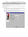
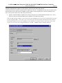
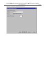
Add BICs (sequencer and units) and dummy CDs to either a new or existing LNS network......................................... 32
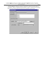
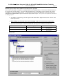
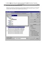
Configure the LNS data base so that the BIC uses a device specific resource file ......................................................... 36
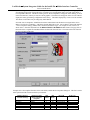
Add boiler function blocks (objects) for the sequencer and each of the units to the network......................................... 39
Bind the Sequencer BIC to the Unit BICs for normal sequencer operation.................................................................... 41
Order replacement CDs................................................................................................................................................... 44
Make custom graphical user interfaces to display system status .................................................................................... 46
Reprogramming CDs Task .................................................................................................................................................... 46
Prepare to connect LonWorks Network wire to the BIC System Task................................................................................... 46
System Integrator Task – Final Integration (OnNet) .............................................................................................................. 46
Shut down the boiler system ........................................................................................................................................... 46
Remove the CDs from the system................................................................................................................................... 46
Connect the BIC System to the building LonWorks Network........................................................................................ 46
Commission the BICs ..................................................................................................................................................... 47
Install the replacement CDs ............................................................................................................................................ 52
Return the boiler system to operation ............................................................................................................................. 52
Test any network functions............................................................................................................................................. 52
Appendix A – Network variable description .............................................................................................................................. 53
Who should read the System Integrators Guide?
The system integrators guide is designed for use by anyone that could benefit by connecting the Intelli-Fin unit to a
LonWorks building automation system. Specifically consulting engineers, and building owners will find the Benefits of
System Integration section useful. LonMark system integrators will find the detailed information required to integrate the
LonWorks System Integrator Guide for the Intelli-Fin Boiler Interface Controller
Version LOCH SIG-01
Page 4
Intelli-Fin into a building automation system. System Integrators are expected to have previous experience with LonWorks
systems.
This document is intended to be used by LonMark system integrators that use LNS based tools, but information included
here may enable system integrators to integrate Intelli-Fin boilers in to other systems.
Abbreviations used in this document
BAS
BIC
Binding
CD
Configuration
Parameters
Device or
Node
LNS
PC
Object
Site or System
Sequencer
Unit
Building automation system that uses LonWorks digital communications to exchange information between
the equipment and human interfaces in the system.
Boiler Interface Controller for Lochinvar Intelli-Fin units. Sometimes the BICs are referred to as XL10
controllers.
The process of logically connecting the information in a source node to the information in a destination
node(s). When the information in the source node changes, the new value is automatically communicated to
the destination node(s) over the LonWorks network.
Command Display Module – A dedicated human interface for the BIC. Also known as a HIP (Human
interface Panel)
A device or object performs various predetermined and fixed functions that are selected by variables called
configuration parameters. The configuration parameters may select various functions from a repertoire of
functions or the configuration parameter may vary the function in some way (such as change the gain in a
PID control loop).
An electronic module that controls mechanical equipment, displays controller information to a human, or
connects the communications network to another network. The nodes communicate with one another over the
LonWorks network.
LonWorks Network Services - A server used by network tools to manage, monitor, and control the nodes on
LonWorks networks.
Personal computer work station running building management software
Each device contains one or more object. Each object has defined inputs, outputs, configuration parameters,
and predetermined functionality.
A site or system is one building or one campus. A site consists of several devices connected together by one
LonWorks network. Even if the devices are miles apart, they may belong to one site if one LonWorks
network interconnects them.
A sequencer is a device that controls several units that are connected together for greater heating capacity.
The sequencer controls the water temperature by commanding the several units to turn on or off depending
on the water temperature. The sequencer directs which units are firing at each moment and also directs the
firing rate of each unit when they are turned on.
Refers generically to either Boilers or Water Heaters. Intelli-Fin units may either be boilers (for supplying
hot water for heating systems or water heaters for supplying hot water for some process). More details
requirements will be specifically called out.
Trademarks
Intelli-Fin is a registered trademark of Lochinvar Corporation
Echelon, and Neuron are U.S. registered trademarks of Echelon Corporation. LonMark, LonWorks, LonTalk, LonBuilder,
and LNS, are trademarks of Echelon Corporation.
References
“LonMark Application Layer Interoperability Guidelines” Revision 3.2 by LonMark Interoperability Association
“LonMark Layers 1 – 6 Interoperability Guidelines” Revision 3.0 by LonMark Interoperability Association
“LonMark External Interface File Reference Guide” Revision 4.0A by Echelon Corporation
“LonMark Resource File Developer’s Guide” by Echelon Corporation
“LonWorks Technology device Data” by Motorola
“SNVT Master List and Programmers Guide” by Echelon Corporation
“The LonWorks Network Services (LNS) Architecture Strategic Overview” white paper by Echelon Corporation
“The LonWorks Network Services (LNS) Architecture Technical Overview” white paper by Echelon Corporation
“LNS Programmers' Guide for Windows” by Echelon Corporation
“Junction Box and Wiring Guideline for Twisted Pair LonWorks Networks” by Echelon Corporation
LonWorks System Integrator Guide for the Intelli-Fin Boiler Interface Controller
Version LOCH SIG-01
Page 5
“Installation and Service Manual - Intelli-Fin Hot Water Heating Boilers” by Lochinvar
See www.echelon.com for more information about LonWorks.
See www.lonmark.com for more information about LonMark
Benefits of System Integration
The benefits of integrating equipment into a building automation system generally are:
• Reduced energy cost
• Improved comfort, and / or safety for building occupants
• Accommodate building use by enabling unique functions
• Reduced equipment maintenance cost
• Information sharing to reduce installed cost
The benefits are enabled because the building equipment can “talk” to one another, can “report” certain conditions
automatically to a remote location, and can be “reprogrammed” . For example:
•
Energy is saved by reducing comfort when the building or a space in the building is not occupied. The space
temperature can be allowed to float higher or lower when the building is not occupied.
•
Automatic off site monitoring of building equipment is an economic way of providing equipment maintenance only
when needed. A single off site monitoring station can monitor hundreds of buildings with little or no human
intervention.
•
By keeping track of equipment run time, maintenance can be “requested” by the equipment when it is time for
maintenance.
•
By viewing the current operating conditions of building equipment over a remote communications connection
(telephone line), a technician can often diagnose a problem from his office. The service person can be sure to bring
the required parts on his truck when he visits the site.
•
Many temporary “repairs” may be made over a remote communications connection to keep the building running at
reduced functionally or efficiency, until a service person can visit the site.
•
Periodically the operating conditions of building equipment can be entered into a “trend log”. The log can later be
viewed on a PC to show system performance. The log can verify that the system is (or is not) operating properly
without a person having to be there to watch a system operate. Trend logs can be used for troubleshooting
complaints made by building occupants.
•
The control strategies can be tuned to decrease maintenance, and increase comfort. By viewing a carefully designed
trend log, operating parameters of the equipment may be tuned for a desired result.
•
The equipment may cooperate in an emergency. For example: In case of a fire, ventilation is turned off in the fire
area reducing the oxygen available to the fire while other areas are pressurized to reduce smoke damage. After the
fire, outside air is used to purge the smoke from the building.
•
Some sensors may be shared by many devices. For example: One outside air temperature sensor may be shared by
many controllers resulting in lower installed cost.
•
Custom features may be added to the building to accommodate the building use. For example:
1.
2.
3.
An industrial process that requires hot water may cause the boiler (water heater) temperature to be high only
when the process is operating to save energy.
A building owner may wish to charge extra energy cost when the building is occupied beyond normal hours. A
billing device may monitor building occupancy to bill the tenant when the space is occupied beyond normal
hours.
In a multi-unit system, a custom unit sequence may be implemented by the system integrator.
LonWorks System Integrator Guide for the Intelli-Fin Boiler Interface Controller
Version LOCH SIG-01
Page 6
When equipment can “talk” to one another, each piece of equipment is capable of some system functionality. The BIC is able
to:
Note: See “BIC Details” for a complete list of features. Items marked with * are currently not available for integration in a
BIC system.
Control the temperature of the water supplied by the unit(s):
• One BIC controls one unit that supplies hot water for building heat or another process
• More than one BIC and unit can be connected together to increase system heating capacity
• One BIC acts to sequence several units on / off with variable firing rates
Receive information and commands from other devices:
• Unit and Pump Commands *
• Outdoor temperature *
• Water temperature set point of the water may be adjusted by a schedule and remotely *
• Occupancy sensor may over ride the schedule *
• Unit BICs may be sequenced by one sequencer BIC
Send information to other devices:
• Occupancy sensor *
• Outdoor temperature of local sensor *
• One sequencer BIC can be configured to sequence other unit BICs
Report to a human operator or automatic device:
• Return, supply, and bypass water temperature
• Outdoor temperature
• Effective set point and Occupancy state
• Pump status
• Variable firing rate, bypass, and boiler load percentage or water heater recovery rate
• This BIC is the unit sequencer (otherwise it is a unit controller)
• Detailed unit operation states – For example: Hot Surface Igniter, Gas valve
• Alarms - For example: Sensor, Communications or Flame Failure; Low Air Pressure Water Flow or Gas Pressure;
Invalid Set Points or Configurations; Device Disabled; High Temperature; Boiler not Operating; Heat Mode Fail;
Blocked Drain
• Name identifier and BIC Program version
Receive information from a human operator:
• Temperature set points for occupied and unoccupied state
• Manual Control for trouble shooting *
• Manual Occupancy override *
• Run Time Limit *
When the functionality of all the devices in a system are put together the benefits of system integration can be realized. For
example the following devices may be shared by BICs and other controllers to provide benefits that the BIC alone could not
provide:
Note: See “BIC Details” for a complete list of features. Items marked with * are currently not available for integration in a
BIC system.
•
Occupancy scheduler to provides occupancy related energy savings through a schedule for building occupancy *
•
Occupancy override provides one or more means for overriding the schedule when the building becomes occupied
during a scheduled unoccupied period. Typically a user interface (may be a PC) is used to initiate an override period
but turning on the lights manually or disarming the security system could be used to indicated occupancy. *
•
Off site communications device enables remote control and monitoring. For example:
LonWorks System Integrator Guide for the Intelli-Fin Boiler Interface Controller
Version LOCH SIG-01
1.
2.
The Echelon Serial LonTalk Adapter (SLTA) and a modem connects between a dial up analog telephone line
and the LonWorks Network so a remote PC may monitor and control the building.
Internet server connects between a LonWorks network and the Internet (TC/IP) network enable a PC with
Internet browser to monitor and control a building.
•
An alarm logging device that receives alarms from devices and periodically checks devices for out of range
conditions reports alarms to local and / or remote PCs.
•
A trend logging device periodically records information from devices to store a trend log for troubleshooting.
•
A user interface PC running building management software may do one or more of the following:
1.
2.
3.
4.
5.
6.
7.
8.
9.
•
Page 7
Local and / or remote communications to various sites including dial in capability for remote alarm logging.
Display a list of all the sites known to the building management software and a list of devices at each site.
Display the current status of devices.
Display and change occupancy schedules, zone set points, manual occupancy and other parameters.
Display and configure the alarm and trend logs.
Advanced features for multi site monitoring (scheduled periodic monitoring of buildings, change the schedule at
multiple sites with only one entry, and others)
Manage user permissions, restricting the functions available to each user according to job description.
Configuration of the devices and the network (available only to installers and system integrators)
Manually control devices (available only to installers)
Other devices may be needed in the system as determined by the application requirements and system integrator.
LonWorks overview
Some of the features of the LonWorks system are:
•
All devices use the LonTalk protocol defined and documented by Echelon Corporation. The protocol defines the
electrical communications signals used by devices, the type of wire to use between devices, and how information is
exchanged between the devices.
•
Each device contains a unique identifier called the neuron – id. Most devices contain a microprocessor called the
“neuron” and each neuron is given a unique 48 bit identifier at the time of manufacture. The neuron – id is read by a
PC tool during the installation process. An example of a neuron – id is the hexadecimal number 00 01 3F EE 2F 7A.
•
Each device has a unique address identifier. The unique addresses are assigned by a system integrator using a PC
tool that keeps track of all the devices and their addresses in the system. The neuron – ids, addresses, device names,
and device types are saved in the tool data base.
•
Each device has information that may be shared with other devices. The information is stored in each device in
“network variables” and optionally in “files”. Each device type has a set of network variables and files unique to
the device type. PC tools read computer files that tell them what network variables and files are available in each
device type. See “BIC Details” for a list of network variables found in the BIC.
•
A device will report a network variable to other devices when ask or “polled” by another device. For example: water
temperature, device state, alarms, etc, may be polled by a PC to display the current values on the screen. The PC
needs a data base of device addresses, device names, and device types to retrieve and display information from
devices.
•
A network variable in a source device may be “bound” to volunteer information to destination device(s). For
example: the output network variable on the outdoor air temperature sensor may be bound (connected) to all the
network variable inputs on devices that use outdoor air temperature. When ever outdoor air temperature changes, the
sensor sends the new temperature to all the devices that need it. Binding is done by the system integrator using a PC
tool to tell the devices to bind the network variable output in one device to input network variables in another
device(s). The binding information is saved in the PC tool data base.
LonWorks System Integrator Guide for the Intelli-Fin Boiler Interface Controller
Version LOCH SIG-01
Page 8
•
All bound network variables are volunteered by the source device when the network variable value changes
•
Some bound network variables may also be volunteered by the source device periodically even if no change has been
made. The periodic volunteering of information is called the heart – beat, and is used by the destination device(s) to
determine that the source node is still working. If the destination device fails to receive the information periodically,
the destination device will take alternative action.
•
Some of the input network variables or files are stored in non-volatile memory and used by the device to tailor the
device operation to the application. These variables are called “configuration parameters” and are set by the installer
or system integrator using a PC tool. The configuration parameters are saved in the PC tool data base.
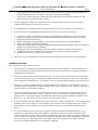
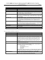
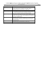
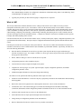
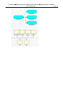
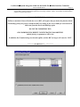
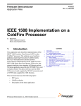
Remote PC Monitoring
Software
Local PC Commissioning Tool
and / or PC Monitoring Software
MODEM
MODEM
Command
Display Module
Serial LonTalk
Adapter
LonW orks Network
Serial LonTalk
Adapter
Boiler’s
Other
Controls
BIC’s
Alarm and
Trend Logger
Scheduler
HVAC
Lighting
Security
Elevator
Other
SENSORS
ACTUATORS
Typical LonWorks Building Automation System with many features
interconnected on the LonWorks network.
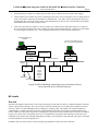
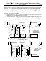
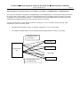
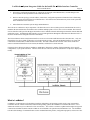
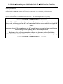
BIC details
One unit
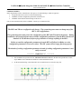
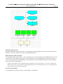
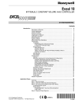
The basic unit diagram is shown below. Fuel (such as natural gas), mixed with air, burns in a combustion chamber to heat the
water in a primary heat exchanger. The water is also pre-heated by exhaust gases in a secondary heat exchanger to increase
efficiency. Water is circulated through the heat exchangers by a primary pump. The amount of air (and fuel) supplied is
controlled using a variable speed fan. Fan speed is controlled using an electronic circuit called a variable frequency drive
(VFD). A BIC can control water temperature by changing the speed of the fan and cycling the burner off and on. In addition
a bypass valve allows some of the heated water to be re-circulated back to the primary heat exchanger to control the water
temperature in the primary heat exchanger independent of loading. The temperatures measured at the inlet, bypass, and outlet
are used to adjust the air flow and bypass valve.
In addition, there are safety features to ensure the following conditions are met before fuel is turned on:
LonWorks System Integrator Guide for the Intelli-Fin Boiler Interface Controller
•
•
•
•
•
•
•
Version LOCH SIG-01
Page 9
There is water flowing in the heat exchanger
There is no unburned fuel in the combustion chamber or flue before the burner flame is ignited
There is air flow and the flue is not blocked
The drain for the water that condenses from the exhaust gas is not blocked
The gas pressure is within tolerances
The ignition system is working
After the fire has been established, the outlet and inlet temperatures are compared to show that water is actually being
heated.
Re circulation
(Bypass) Valve
VFD
T1
Inlet Water
Temperature
Secondary
Heat
Exchanger
T3
Bypass
Water
Temperature
Primary
Pump
Heat
Exchanger
(Primary)
T2
Outlet Water Temperature
Combustion Waste-Gas Heat
Intelli- Fin Block diagram
One BIC controls the temperature of the water delivered by one unit. A BIC receives the water temperature and other
information from sensors, and commands the fan, bypass valve, and ignition system to heat the water. The BIC also interfaces
via a LonWorks network to other equipment for system wide coordination and reporting.
LonWorks System Integrator Guide for the Intelli-Fin Boiler Interface Controller
Version LOCH SIG-01
Page 10
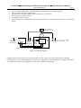
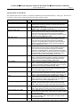
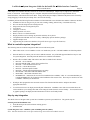
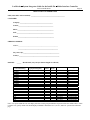
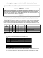
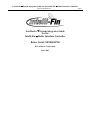
The wiring diagram below shows the typical connection between the BIC and the safety sensors and
controls. This wiring drawing is not to be used for wiring or interface details. It is to be used for an
overview of boiler operation only.
120
VAC
Flame
Failure
Circuit
Breaker
LWCO
T'STA
T
HILIMI
T
HSI
ON
24 VAC
-
+
Low
H20
Rela
y
24 VAC
IN
PRESSURE
SWITCHES
GAS
PRESSURE
Air
FLOW HIGH LOW Flow
24 VAC
IN
24
VAC
OUT
Blocked
BlockedBlocked
Louver
Drain Flue
Flame Fenwall
Failure
Thermosta
t
Igniter 120V
AC
Input
Relay OUT
Pressure
Switch Input
Gas
Valve
Relay
To120
VAC
Blower
Relay
Common
Normally
Open
ANALOG OUT
FROM XL10
VFD
Excel 10 Ignit
Relay
TO
120VA
C NEU
MTR
120 VAC
GAS
GAS VALVE
GAS
Bypass Valve
Control (Floating)
Bypass
Valve
OUTPUT
FROM XL10 Low Water or
Flow
GAS ON
H20
H20
AIR/DRAIN
RESISTOR DIVIDER
FLUE-LOUVER/GAS
RESISTOR DIVIDER
LonWorks System Integrator Guide for the Intelli-Fin Boiler Interface Controller
Version LOCH SIG-01
Page 11
The physical inputs connected between the unit and the BIC are listed below:
Input
Inlet Water Temperature
Outlet Water Temperature
Bypass Water Temperature
Outdoor Air Temperature(Optional)
Low Air and Blocked Drain Input
Low Gas Pressure Input and Blocked
Flue
Time Clock Input
Manual Disable
HSI Status
Gas Valve Status
Low Water Flow
Hard Lockout
Function
Measure inlet water temperature
Measure outlet water temperature
Measure water temperature entering the primary heat exchanger
Measure outdoor temperature
Indicate loss of airflow or drain blockage from the low air pressure sensor and
blocked drain sensor. (External switches and resistor network used to create 2 to
10 volts input voltages to indicate switch status)
Indicates gas pressure problem or blocked flue from the high and low gas
pressure sensor and blocked flue sensor. (External switches and resistor network
used o create 2 to 10 volts input voltages to indicate switch status) – Applies only
to a unit controller.
Scheduled building occupancy. Used to determine the temperature set point of
the control system. (External switches and resistor network used to create 2 to 10
volts input voltages to indicate switch status) – Uses the same physical input as
the Low Gas Pressure Input and Blocked Flue sensor – Applies only to the
sequencer.
Manual request to disable the unit . Manual disable is not a power disconnect.
The controller still has power present, but will shut down firing, or prevent starting
to fire. If the unit is firing, a post-purge sequence is performed. A disabled unit will
allow the pump to operate if configured for Continuous Pump.
Indication of HSI On from the ignition device.
Indicates that power has been applied to the gas valve solenoid implying that gas
is being supplied.
Indicates loss of pump water flow from water level or water flow sensor.
Indicates flame failure from Ignition device.
The physical outputs from the BIC are listed below:
Output
Primary Pump
Aux. Call for Heat
Ignition control
Bypass Open
Bypass Close
Dial Out Alarm
Variable Speed Blower
Function
Turns water pump off and on.
Turns Auxiliary relay off and on.
Turns the ignition control (to Fenwal Unit) off and on.
Bypass floating control 24 vac output causes the bypass valve to open. The
analog bypass valve allows hot supply water to mix with colder inlet water in the
primary heat exchanger to avoid condensation on the primary heat exchanger.
Only the secondary heat exchanger is allowed to have condensation. This
floating output is attached to a bypass floating valve actuator and causes the
valve to slowly open. The typical motor travel time from stop to stop is 160
seconds.
Bypass floating control 24 vac output causes the bypass valve to slowly close.
See Bypass Open description above.
On/Off for external phone system dial out alarm to third party device. The third
party device is Sensaphone Model 1104 dial-out device. A dial out alarm is
commanded due to one or more of the following:
•
water flow failure
•
low or high gas pressure fail
•
blocked drain
•
flame failure
Optional output for stand alone systems. Several BIC Dial Out Alarm outputs may
be connected in parallel to one dial out device. Each Sensaphone Model 1104
is capable of annunciating four unique messages for via 4 unique digital inputs.
Control the speed of the variable speed blower motor. This pulse width
modulation output is attached to an analog output converter that drives a variable
frequency drive to control the speed of the air supply blower.
LonWorks System Integrator Guide for the Intelli-Fin Boiler Interface Controller
Version LOCH SIG-01
Page 12
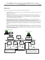
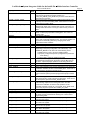
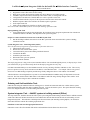
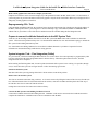
Multiple units for increased capacity
To increase the capacity of a system, it is possible to connect the units together with piping and controls as illustrated in the
figures below. There is a BIC for each unit that monitors the inlet and outlet temperatures for each unit and controls the
ignition, fan speed, and bypass valve. In addition there may be a BIC configured to be a sequencer. The sequencer BIC
monitors the system supply and return temperatures, and controls the System Pump. In addition the sequencer BIC
commands the units to turn on / off and controls the firing rate of each unit in predetermined sequences. The sequencer BIC
communicates with the unit BICs over a LonWorks network via network variables designed for sequence control.
The sequencer can be configured at the factory for:
• First unit On First unit Off. Example: If the boilers turn on in the 1,2,and 3 turn sequence, then when there is less
demand for heat, stage 1 is turned off first, then stage 2, then stage 3.
• First unit On Last unit Off. Example: If the boilers turn on in the 1,2,and 3 turn sequence, then when there is less
demand for heat, stage 3 is turned off first , then stage 2, then stage 1.
• Efficiency Optimized. More boilers run at a time at a lower firing rate instead of one boiler at a higher firing rate
• Efficiency Optimized Run time equalization. Same as Efficiency Optimized except with equal run time on all
boilers.
System Return Temp
*
Hot Water Loop
*
Unit 1
*
Unit 2
BIC #1
BIC #2
System Supply Temp
System Pump
* -- pipes to be 12
inch max apart or 4
pipe diameters apart
Unit 3
BIC #3
Sequencer BIC
LonWorks Bus
Up to three units connected
System Return Temp
Hot Water Loop
*
*
System Supply Temp
System Pump
Unit 1
Unit 4
Unit 2
Unit 5
Unit 3
Unit 6
* -- pipes to be 12 inch
max apart or 4 pipe
diameters apart.
Sequencer BIC
LonWorks System Integrator Guide for the Intelli-Fin Boiler Interface Controller
Version LOCH SIG-01
More than three units connected
Page 13
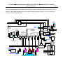
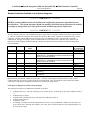
Intended uses
There are several intended usage scenarios of the BIC as illustrated by the diagram below.
•
Single stand alone unit. One BIC controls one unit. Command display module is local human interface for the unit.
Optional dial out alarm system.
•
Multiple sequenced units. Up to 16 units connected together in a group for increased capacity. Each unit is
controlled by a BIC. An additional BIC is the sequencer. Command display module is the local human interface for
the units and sequencer. Optional local hardwired time clock connected to the sequencer. Optional dial out alarm
system (all alarm outputs may be wired in parallel).
•
Multiple sequenced units with network local or remote monitoring. Up to 16 units connected together in a
group for increased capacity. Each unit is controlled by a BIC. An additional BIC is the sequencer. Local or remote
IntelliStation PC monitoring software. Local command display module. Optional local hardwired time clock.
Optional dial out alarm system (all alarm outputs may be wired in parallel). There may be one or more sequenced
group monitored by IntelliStation monitoring software. IntelliStation is a full featured workstation made specifically
for BIC.
•
Multiple sequenced units integrated into a building automation system. Up to 16 units connected together in a
group for increased capacity. Each unit is controlled by a BIC. An additional BIC is the sequencer. Local command
display module. Third party local or remote workstation monitors the system. There may be one or more sequenced
group monitored by the workstation.
Remote PC Monitoring Software
Local PC Monitoring Tool
MODEM
MODEM
Command
Display
Serial Lon Talk
Adapter
LonWorks
NETWORK
Mod Boiler #1
BIC
SENSORS
Mod Boiler #2
BIC
SENSORS
ACTUATORS
ACTUATORS
LOW COST DIAL OUT DEVICE
Sensaphone 1104 (provided as on option
by Lochinvar) This device provides dial out
alarm management of an alarm input from
the Bic Controller.
Serial Lon Talk
Adapter
Mod Boiler #3
BIC
SENSORS
ACTUATORS
Sequencer
BIC
SENSORS
ACTUATORS
ELECTRONIC 24 HR PROGRAM TIMER
OMRON H5L-A (provided as on option by Lochinvar)
. This electronic timer provides a dry contact
Input to the Sequencer to provide a programmable
Setback time available over a 7 day schedule
LonWorks System Integrator Guide for the Intelli-Fin Boiler Interface Controller
Version LOCH SIG-01
Page 14
Network Variables Available to the System Integrator
********* WARNING !!!! *********
The BIC contains additional network variables and configuration parameters other than the ones
described here. The system integrator should not attempt to bind to the unspecified network variables
or attempt to change them since some of the network variables may present safety issues.
********* WARNING !!!! *********
The BIC contains two objects. The LonMark node object (object number 0) and the Lochinvar boiler object (object number
1). Network variables are assigned to each of them. The following BIC network variables are available for use by system
integrators. The BIC contains other network variables, but they are intended for factory configuration, or for future
enhancements. Changing or binding to network variables that are not described below could cause safety problems and
therefore the system integrator should not attempt to change the unspecified network variables or bind to the unspecified
network variables.
Object
Node (0)
Node (0)
Node (0)
NV1
NV2
SCPT 25
Boiler (1)
UNVT 1
Boiler (1)
Boiler (1)
Boiler (1)
Boiler (1)
Boiler (1)
NV1
NV2
NV3
NV4
NV5
Boiler (1)
NV6
Network variable
Mechanism
name
nviRequest
Input network variable
nvoStatus
Output network variable
nciConfigSr
Configuration parameter network variable stored in non volatile memory - EEPROM life is limited to 10,000 writes and
should not be written frequently
nciOAReset
Configuration parameter network variable stored in non volatile memory - EEPROM life is limited to 10,000 writes and
should not be written frequently
nvoData
Polled output network variable
nvoIO
Polled output network variable
nviSeqShare
Input to units bound to sequencer
nviModBoilrShare
Inputs to sequencer bound to units
nvoSeqShare
Output from sequencer bound to units – commands unit
sequencing
nvoModBoilrShare Output from units bound to sequencer – Feedback from units
to sequencer
Data Structure
in resource file
SNVT_obj_request
SNVT_obj_status
SNVT_config_src
UNVT_oa_reset
UNVT_ctl_data
UNVT_io
UNVT_seq_share
UNVT_mod_share
UNVT_seq_share
UNVT_mod_share
More details for each network variable are given below. All of the variables apply to the BIC when it is used as a unit
controller and when it is used as a sequencer unless specifically stated. There is no difference between the boiler and the
water heater except that the configuration parameters are set differently at the factory.
Node Object (nviRequest, nvoStatus, and nciConfigSr)
The following fields have been implemented in the BIC node object.
•
•
•
•
•
•
nviRequest.object_id. The only valid object_id is 1 (boiler object). All other object_ids return nvoStatus.invalid_id
= 1.
nviRequest.object_request
nvoStatus.ojbect_id returns the object_id requested by nviRequest.object_id
nvoStatus.invalid_request
nvoStatus.in_alarm
nciConfigSr is available for network management tools to set to CFG_EXTERNAL when the network image is set
by an outside source. Normally nciConfigSr is set to CFG_LOCAL when the node uses pre assigned binding to set
its own network image.
LonWorks System Integrator Guide for the Intelli-Fin Boiler Interface Controller
Version LOCH SIG-01
The following nviReqest.object_request states have been implemented:
object_request state
RQ_NORMAL
RQ_UPDATE_STATUS
RQ_REPORT_MASK
RQ_MANUAL_CTRL
RQ_DISABLED
RQ_ENABLE
others
Action taken
Switch to normal mode and report any alarms in nvoStatus.in_alarm. If
the BIC (nvoDate.mode) is in MANUAL, FACTORY_TEST or
DISABLED_MODE, restart at START_UP_WAIT mode.
Report the current node status in nvoStatus.in_alarm.
Report the supported functions of nvoStatus. nvoStatus.in_alarm is set to
1. nvoStatus.report_mask has not been implement. Therefore the node
object is not in compliance with the current LonMark standards.
Switch to manual control and report nvoStatus.in_alarm. If the BIC
(nvoDate.mode) is not already in FACTORY_TEST or MANUAL modes,
the BIC is set to either FACTORY_TEST or MANUAL mode depending
on the value of nviManualValue.
If the BIC is not already in DISABLED_MODE, switch to
DISABLED_MODE. If the BIC is in MANUAL or FACTORY_TEST, the
mode is switched to START_UP_WAIT first and then later switches to
DISABLED_MODE.
If the BIC (nvoDate.mode) is in MANUAL, FACTORY_TEST or
DISABLED_MODE, restart at START_UP_WAIT mode.
nvoStatus.invalid_request is set to 1.
Page 15
LonWorks System Integrator Guide for the Intelli-Fin Boiler Interface Controller
Version LOCH SIG-01
Page 16
Data sharing between units and sequencer (nvoSeqShare, nviSeqShare, nvoModBoilrShare, nviModBoilrShare)
The variables nvoSeqShare, nviSeqShare, nvoModBoilrShare and nviModBoilrShare, are used to share information between
the sequencer BIC and the unit BICs. Specifically the SEQUENCER uses nvoSeqShare connected (bound) to the UNITS
nviSeqShare to request and modulate unit heat. Feedback from the UNITS nvoModBoilrShare connected (bound) to the
SEQUENCER nvoModBoilrShare reports the actual unit response to the request.
Generally the information in these variables should not be displayed or viewed. The other variables have BIC status
information in a more user friendly format.
•
SEQUENCER.nvoSeqShare bound to all UnitBIC.nviSeqShare in a one to many binding.
•
All UnitBIC.nvoModBoilrShare bound to SEQUENCER.nviModBoilrShare in a many to one binding.
nvoSeqShare bound
to nviSeqShare
UNIT BIC 1
UNIT BIC 2
SEQUENCER
BIC
Other UNITs
UNIT BIC n
nvoModBoilrShare bound
to nviModBoilrShare
LonWorks System Integrator Guide for the Intelli-Fin Boiler Interface Controller
Version LOCH SIG-01
Page 17
Operating Mode (nvoData.Mode)
The operating mode or state of a BIC is reported by nvoData.mode (an enumerated data type – stmd_type). The states are
given below. States apply to units and not sequencers unless otherwise stated.
Displayed
START_UP_WAIT
Raw
Value
0
IDLE
1
WATER_FLOW_EVAL
2
AIR_PRES_EVAL
3
BLOCK_DRAIN_EVAL
4
LOW_GAS_PRESS_EVAL
5
PRE_PURGE
6
IGNITION_EVAL
7
BOILER_ON_EVAL
8
HEAT
9
WATER_FLOW_FAIL_MODE
10
AIR_PRESS_FAIL_MODE
11
BLOCK_DRAIN_FAIL_MODE
12
BLOCK_FLUE_FAIL_MODE
13
LOW_GAS_PRESS_FAIL_MODE
14
Meaning
The BIC has recently been reset due to power failure or other
software reset and is going through an internal start up process.
Also applies to sequencers.
There currently is no call for heat and the unit is currently not
heating water. Also applies to sequencers.
There is a call for heat but the unit is not currently heating water.
The BIC has turned on the pump to circulate water through the
unit, set the fan to the purge speed to purge the combustion
chamber of combustible gases, and is evaluating water flow before
proceeding to AIR_PRES_EVAL mode.
There is a call for heat but the unit is not currently heating water.
The BIC has turned on the pump to circulate water through the
unit, set the fan to the purge speed to purge the combustion
chamber of combustible gases. All previous steps have passed.
The BIC is checking the flue air pressure before proceeding to
BLOCK_DRAIN_EVAL mode.
There is a call for heat but the unit is not currently heating water.
The BIC has turned on the pump to circulate water through the
unit, set the fan to the purge speed to purge the combustion
chamber of combustible gases. All previous steps have passed.
The BIC is checking that the condensate water drain is not blocked
(if equipped with an optional condensate management system)
before proceeding to LOW_GAS_PRESS_EVAL mode
There is currently a call for heat but the unit is not currently heating
water. All previous steps have passed. The BIC is checking for
sufficient gas pressure (if equipped with optional gas pressure
switches) before proceeding to PRE_PURGE mode.
There is currently a call for heat but the unit is not currently heating
water. All previous steps have passed and the fan is continuing to
purge the combustion chamber of combustible gases for a period
of time before proceeding to IGNITION_EVAL mode
There is a call for heat but the unit is not currently heating water.
The Ignition request to the Fenwal control panel has been made.
Proceed to BOILER_ON_EVAL mode.
There is a call for heat and the unit should be heating water. The
inlet and outlet water temperatures are being compared to show
that the unit is heating water before proceeding to the HEAT mode.
There is a call for heat and the unit is heating water. The fan
speed and bypass valve position are being adjusted to maintain the
water temperature set points. When heat is no longer called for,
proceed to the POST_PURGE_PREPARE mode.
The primary pump is on but no water flow through the unit is
detected. The fan and pump are on but the unit is not heating
water. When there is no longer a call for heat, proceed to IDLE.
The fan has been turned on but no flue air pressure has been
detected. The fan and pump are on but the unit is not heating
water. When there is no longer a call for heat, proceed to IDLE.
The condensate water drain is blocked. The fan and pump are on
but the unit is not heating water. When there is no longer a call for
heat, proceed to IDLE.
A blocked flue has been detected. The fan and pump are on but
the unit is not heating water. When there is no longer a call for
heat, proceed to IDLE.
There is a problem with the gas pressure. The fan and pump are
on but the unit is not heating water. When there is no longer a call
LonWorks System Integrator Guide for the Intelli-Fin Boiler Interface Controller
Version LOCH SIG-01
Displayed
Raw
Value
FLAME_FAILURE_MODE
15
SOFT_LOCK_OUT_FAIL_MODE
16
HEAT_MOD_FAIL_MODE
17
MANUAL
FACTORY_TEST
18
19
PUMP_ONLY
EMERGENCY_MODE
DISABLED_MODE
20
21
22
HIGH_TEMP_MODE
23
OFF_MODE
SMOKE_EMERGENCY
POST_PURGE
24
25
26
FREEZE_PROTECT_MODE
27
POST_PURGE_PREPARE
28
FLOAT_OUT_SYNC
29
IDLE_MIN_DELAY
SPARE_MODE2
SEQ_HEAT_0STGS
30
31
32
SEQ_HEAT_1STGS
33
SEQ_HEAT_2STGS
34
SEQ_HEAT_3STGS
35
SEQ_HEAT_4STGS
36
SEQ_HEAT_5STGS
37
Meaning
for heat, proceed to IDLE. (Some units are wired to connect the
high and low gas pressure sensors together so a
LOW_GAS_PRESS_FAIL_MODE may in fact be issued when the
gas pressure is too high)
The Fenwal Ignition Controller has indicated a flame failure (Hard
Lockout). The unit is not heating water. When there is no longer a
call for heat, proceed to IDLE.
There is a call for heat but no heat has been detected during
BOILER_ON_EVAL and 5 minutes have gone by. The unit is not
heating water. When there is no longer a call for heat, proceed to
IDLE.
There is a call for heat. Heat has been detected but then the heat
failed. A failure purge operation is taking place. The unit is not
heating water.
Not currently supported.
The BIC is in the factory test mode. A BIC should never be in the
factory test mode while operating a unit. The only way the BIC can
be put into a FACTORY_TEST is by changing some of the
unspecified network variables.
Not currently supported.
Not currently supported.
The unit is not heating water but the pump may be on or off
depending on the pump configuration set at the factory. The
DISABLED_MODE occurs when one of the following is true:
• Disable switch on unit is set in the disable position
• Improperly configured sequencer (configuration is performed
at the factory)
• A sensor that is critical to operation has failed
If the inlet, outlet, or bypass water temperature exceeds the high
temperature limit configured in the factory, then the BIC turns off
the heat. A post heat purge operation occurs during this mode.
Not currently supported.
Not currently supported.
At the end of a heating cycle, the fan continues to run to purge the
combustion chamber and flue of combustible gases. At the end of
the timed period, proceed to the IDLE mode.
If inlet, outlet, or bypass is less than the factory configured limit,
heat is turned off (with a post heat purge) and the pump is turned
on.
There is no longer a call for heat but the unit is still heating water.
The air flow is set to a rate to prepare for shut down. At the end of
the timed period, proceed to POST_PURGE mode.
There is no call for heat and the BIC is calibrating the floating
control analog outputs such as the bypass valve. The BIC
performs the calibration so that the valve positions can be
accurately reported at power up. The FLOAT_OUT_SYNC mode
occurs only at power up reset, after START_UP_WAIT
Not used.
Not used.
This BIC is the sequencer, is calling for heat and is cycling through
the safety sensors checks before directing one or more units to
begin heating water.
This BIC is the sequencer and is currently requesting heat from
one unit in the system.
This BIC is the sequencer and is currently requesting heat from
two units in the system.
This BIC is the sequencer and is currently requesting heat from
three units in the system.
This BIC is the sequencer and is currently requesting heat from
four units in the system.
This BIC is the sequencer and is currently requesting heat from
five units in the system.
Page 18
LonWorks System Integrator Guide for the Intelli-Fin Boiler Interface Controller
Version LOCH SIG-01
Displayed
SEQ_HEAT_6STGS
Raw
Value
38
SEQ_HEAT_7STGS
39
SEQ_HEAT_8STGS
40
SEQ_HEAT_9STGS
41
SEQ_HEAT_10STGS
42
SEQ_HEAT_11STGS
43
SEQ_HEAT_12STGS
44
SEQ_HEAT_13STGS
45
SEQ_HEAT_14STGS
46
SEQ_HEAT_15STGS
47
SEQ_HEAT_16STGS
48
Page 19
Meaning
This BIC is the sequencer and is currently requesting heat from six
units in the system.
This BIC is the sequencer and is currently requesting heat from
seven units in the system.
This BIC is the sequencer and is currently requesting heat from
eight units in the system.
This BIC is the sequencer and is currently requesting heat from
nine units in the system.
This BIC is the sequencer and is currently requesting heat from ten
units in the system.
This BIC is the sequencer and is currently requesting heat from
eleven units in the system.
This BIC is the sequencer and is currently requesting heat from
twelve units in the system.
This BIC is the sequencer and is currently requesting heat from
thirteen units in the system.
This BIC is the sequencer and is currently requesting heat from
fourteen units in the system.
This BIC is the sequencer and is currently requesting heat from
fifteen units in the system.
This BIC is the sequencer and is currently requesting heat from
sixteen units in the system.
Time in a given mode (nvoData.ModeTimer)
The BIC may be in a given mode for a period of time before the mode proceeds to the next mode. The time that has been
spent in a given mode is reported in nvoData.ModeTimer which is an unsigned long (two bytes) data type with range of 0 to
65534 seconds. In a sequencer nvoData.ModeTimer starts from the beginning of a call for heat until there is no longer a call
for heat.
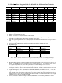
Number of heat stages requested to be turned on (nvoData.HeatStages)
In a sequencer, the sequencer commands the units in the system to turn on or off. nvoData.HeatStages reports the number of
stages (units) currently requested to be turned on by the sequencer. nvoData.HeatStages is an unsigned short (one byte) data
type. In a unit controller, nvoData.HeatStages is one if there is a call for heat, and zero if there is not a call for heat.
Variable frequency drive position (nvoData.VFDPos)
The variable frequency drive position (VFD) determines the speed of the fan and is an indication of how much energy is
being transferred to the water. nvoData.VFDPos, a SNVT_lev_percent data type, reports the percentage (0 to 100 percent)
of fan speed being commanded by the BIC. When the ignition is on, zero percent means the fan is running at 25 percent of full
speed and 100 percent means the fan is running at full speed. In a sequencer, nvoData.VFDPos reports the approximate
overall requested fan speeds of the group of units that it controls.
The relationship between nvoData.VFDpos, VFD frequency, fan speed, and firing rate is linear. The end points are shown in
the table below.
nvoData.VFDpos
(percent)
VFD frequency
(Hz)
0
100
15
60
Fan Speed
(percent of full
speed)
25
100
Firing Rate
(percent of full firing rate)
25
100
The BIC reserves the option (in the future) to command the nvoData.VFDpos to a value grater than minimum to overcome
cold inlet water temps (so condensate does not form on the primary heat exchanger).
Bypass valve position (nvoDataBypassPos)
The temperature of the water in the primary heat exchanger is controlled to prevent condensation in the primary heat
exchanger. Condensation is allowed only in the secondary heat exchanger. Water circulated from the primary heat exchanger
outlet back to the primary heat exchanger inlet is used to keep the primary heat exchanger above the condensation point. A
LonWorks System Integrator Guide for the Intelli-Fin Boiler Interface Controller
Version LOCH SIG-01
Page 20
bypass valve controls the amount of water being re-circulated based on the bypass water temperature. nvoData.BypassPos
(SNVT_lev_percent data type), reports the bypass valve position. When nvoDataBypassPos is zero, the valve is closed, and
when the nvoDayta.BypassPos is 100 percent, the valve is fully open.
The bypass valve is controlled via a floating control electrical connection. The bypass position is only an estimate of valve
position based on how long the valve motor is driven open or closed with a known motor speed. Whenever the valve is
intended to be closed all the way (for example at the end of a heating cycle), the motor is over driven to ensure that the valve
is in a known position.
Bypass valve position does not apply to sequencers.
Boiler Run Time (nvoIO.BlrTotRtHr)
Boiler run time is the number of hours that the unit has been heating water and can be used to schedule unit maintenance. The
run time is saved in non-volatile memory every eight hours of accumulated run time. Therefore a loss of power may cause up
to eight hours of run time to be lost during a power outage. nvoIO.BlrTotRtHr reports the run time in hours. The data type
is unsigned long (two bytes) and has a range from 0 to 65534 hours.
LonWorks System Integrator Guide for the Intelli-Fin Boiler Interface Controller
Version LOCH SIG-01
Page 21
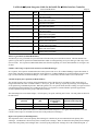
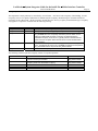
Temperature reports
The variables listed below reports various temperatures in the system.
Variable
Data Type
Range
(Degrees C)
nvoData.InletWaterTemp
SNVT_temp_p
10 to 120
nvoData.OutletWaterTemp
SNVT_temp_p
10 to 120
nvoData.DeltaTemp
SNVT_temp_p
0 to 120
Delta
Degrees
nvoData.BypassTemp
SNVT_temp_p
10 to 120
nvoData.TempControlPt
SNVT_temp_p
10 to 120
Function
Reports the Inlet water temperature. If the BIC is a
sequencer, the temperature reported is the Return
Water temperature.
Reports the Outlet water temperature. If the BIC is
a sequencer, the temperature reported is the Supply
Water temperature.
Reports the Outlet water temperature minus Inlet
water temperature. If the BIC is a sequencer, the
temperature reported is the Supply Water
temperature minus the Return Water temperature.
Reports the temperature of the water entering the
primary heat exchanger. Applies only to a unit
(boiler or water heater). If the BIC is a sequencer,
this sensor is replaced with a resistor and does not
control or report anything meaningful.
Temperature control point. Applies to a single unit or
to a sequencer. If this BIC is a unit being
commanded by a sequencer, temperature control
point is meaningless.
The BIC is trying to heat the water to this
temperature. Either the Inlet (Return) or Outlet
(Supply) water temperature may be controlled as
configured at the factory or selected via the
Command Display.
For boilers the temperature control point is selected
by an algorithm that takes into account the effective
occupancy, the set points entered in the
configuration parameter nciOaReset, and the
outdoor temperature (if equipped with an optional
outdoor air package).
For water heaters, the temperature control point is
selected by an algorithm that takes into account the
effective occupancy, and some of the set points
entered in the configuration parameter nciOaReset.
nvoData.OutsideAirTemp
SNVT_temp_p
-40 to 120
nvoData.CalcWaterFlow
SNVT_flow
0 – 10000
liters per
second
See the Control Point Calculation section for
details.
Reports the outside air temperature. Outside
temperature is only used by a single boiler or by a
sequencer with multiple boilers to adjust the control
point based on outdoor air temperature.
Not Used.
LonWorks System Integrator Guide for the Intelli-Fin Boiler Interface Controller
Version LOCH SIG-01
Page 22
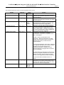
On / Off information
All information is a one bit boolean (True/False) data type
Variable
nvoData.PrimaryPmp
Function
nvoData.ManDisableIn
Reports that the primary pump (system pump in
sequencers) output is enabled.
Reports that power is being applied to the safety
switches and the ignition system. If all of the safety
requirements have been satisfied, then the ignition
system will light the flame.
Dial out alarm is being commanded due to one or more
of the following:
•
water flow failure
•
low or high gas pressure fail
•
blocked drain
•
flame failure
Reports the state of the disable input to the BIC.
nvoData.GlowBarOnIn
nvoData.GasValveOnIn
Reports the state of the HSI status input to the BIC.
Reports the state of the gas valve input to the BIC.
nvoData.LowWaterFlowIn
Reports the state of the low water flow input to the BIC.
nvoData.FlameFailIn
Reports the state of the hard lockout input to the BIC.
nvoData.LowAirIn
Reports the state of the low air input to the BIC.
nvoData.BlockDrainIn
Reports the state of the blocked drain input to the BIC.
nvoData.LowGasIn
Reports the state of the gas pressure input to the BIC
nvoData.BlockFlueIn
When the BIC is a controller, reports the state of the
blocked flue input. When the BIC is a sequencer,
reports the time clock input.
nvoData.SecondaryPmp
nvoData.LocalAlarm
nvoData.SeqControllerCfg
nvoData.Out7
nvoData.LEDOut
Not used
Not used.
Not Used
Not used
Not used
nvoData.IgnitEnab
and
nvoData.AuxCallHeat
nvoData.DialOutAlarm
True
False
Pump on
Pump off
Ignition
power on
Ignition
power off
Alarm
No Alarm
Disable
switch is
in “RUN”
mode
HSI On
Gas Valve
is On
Low water
level or no
water flow
Disable
switch is in
“STOP”
mode
HSI Off
Gas valve is
off
Water level
is OK or
adequate
water flow
Flame OK or
no flame
required
No flame
detected
when
there
should be
a flame
Low air
detected
Blocked
drain
The gas
pressure
is low or
high.
Flue
Blocked or
scheduled
to be
occupied
Air flow is
OK
Drain OK
The gas
pressure is
OK.
Flue not
blocked or
scheduled
unoccupied
LonWorks System Integrator Guide for the Intelli-Fin Boiler Interface Controller
Version LOCH SIG-01
Page 23
Occupancy status
The temperature control point may be controlled by several factors. One factor is the occupancy of the building. Several
occupancy sources of occupancy information are arbitrated by the occupancy arbitration logic to calculate an Effective
occupancy for the control point. All the occupancy variables have the SNVT_occupancy enumerated data type. Occupancy
only applies to a sequencer. Each state has the following meaning:
Displayed
OC_OCCUPIED
OC_UNOCCUPIED
OC_BYPASS
Raw Value
0
1
2
OC_STANDBY
3
OC_NUL
0xFF
Meaning
The space is occupied. Typically the set point is set for comfort.
The space is unoccupied. Typically the set point is set for least energy use.
The space is scheduled to be OC_OCCUPIED or scheduled to be
OC_STANDBY but some occupancy information (such as switch on the
wall) has indicated that the space is currently occupied and that the
scheduled occupancy is not correct. Typically a timer is started when the
space becomes occupied. When the timer times out, the schedule takes
over occupancy
The space is not occupied but should be prepared to become occupied
soon. Typically the set point for OC_STANDBY is between the set point for
OC_OCCUPIED and the set point for OC_UNOCCUIPED.
This source of occupancy information is not connected or has failed.
The following variables report the occupancy control of set point temperature
Variable
nvoData.SchedOcc
nvoData.EffectOcc
nvoData.OverRideOcc
nvoData.ManualOcc
nvoData.SensorOcc
Function
Scheduled occupancy determined by a time clock connected
to the time clock input of the BIC.
The effective occupancy state. In this model, the effective
occupancy state is the scheduled occupancy.
For future use
For future use
For future use
Valid Values
OC_OCCUPIED
OC_UNOCCUPIED
OC_OCCUPIED
OC_UNOCCUPIED
LonWorks System Integrator Guide for the Intelli-Fin Boiler Interface Controller
Version LOCH SIG-01
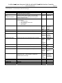
Configuration Parameters setting temperatures
Page 24
All the temperature setting configuration parameters are SNVT_temp_p data type. They apply to all usage scenarios unless
otherwise stated. The temperature setting configuration parameters are used to determine the control point. See the Control
Point Calculation section for more details.
Variable
nciOAReset.SetbackAmt
UN OCCUPIED
nciOaReset.Setpoint
OCCUPIED with out reset
due to outdoor temperature
nciOAReset.MaxSetpoint
OCCUPIED with full reset
due to low outdoor
temperature
nciOAReset.OaMinSetpoint
Outdoor temperature that
causes full reset
nciOAReset.OaMaxSetpoint
Outdoor temperature that
causes no reset
Function
Control point during the Unoccupied
mode
10 to 120
Default Boiler
Value
(Degrees C)
60
In a single boiler unit or boiler
sequencer when the mode is occupied
and the outdoor temperature is
nciOAReset.OaMaxSetpoint or higher,
then the control point is set to
nciOAReset.Setpoint.
10 to 120
71.1
10 to 120
82.2
-60 to 35
-23.3
-60 to 35
15.5
In a single water heater unit or water
heater sequencer when the mode is
occupied, then the control point is set
to nciOAReset.Setpoint.
In a single boiler unit or boiler
sequencer when the mode is occupied
and the outdoor temperature is
nciOAReset.OaMinSetpoint or lower,
then the control point is set to
nciOAReset.MaxSetpoint.
Not used in a water heater.
In a single boiler unit or boiler
sequencer when the mode is occupied
and the outdoor temperature is
nciOAReset.OaMinSetpoint or lower,
then the control point is set to
nciOAReset.MaxSetpoint.
Not used in a water heater.
In a single boiler unit or boiler
sequencer when the mode is occupied
and the outdoor temperature is
nciOAReset.OaMaxSetpoint or higher,
then the control point is set to
nciOAReset.Setpoint.
Range
(Degrees C)
nciOAReset.AbsMaxSetp
Not used in a water heater.
The control point is never allowed to
go above nciOAReset.AbsMaxSetp.
-60 to 200
125.0
nciOAReset.AbsMinSetp
If the measured inlet, outlet, or bypass
temperature exceeds
nciOAReset.AbsMaxSetp, then BIC
enters the HIGH_TEMP_MODE and
the heat is shut off and a post purge
operation is performed.
The control point is never allowed to
go below nciOAReset.AbsMinSetp.
In a single boiler unit or a boiler
sequencer, if the outdoor temperature,
is greater than
nciOAReset.OaHtgLockout, heating
will be turned off.
-60 to 110
50.0
-60 to 35
20.0
10 to 120
54.4
nciOAReset.OaHtgLockout
nciOAReset.EmergSetpoint
Not used in a water heater.
Set point during an emergency – Not
LonWorks System Integrator Guide for the Intelli-Fin Boiler Interface Controller
Version LOCH SIG-01
Variable
Function
Page 25
Range
(Degrees C)
Default Boiler
Value
(Degrees C)
used
Control Point Calculation
The control point is the desired temperature of the water. The sequencer BIC or the one unit BIC calculates the desired water
temperature according to the following table depending on the effective occupancy and the factory configuration:
Effective Occupancy
Factory configuration
(nvoData.EffectOcc)
Water heater or boiler
OC_UNOCCUPIED
Don’t Care
Single Water Heater Unit or Water Heater
Sequencer
nvoData.TempControlPt is
set to the value listed
below
Note 1
nciOAReset.SetbackAmt
nciOAReset.Setpoint.
OC_OCCUPIED
Or
OC_OCCUPIED
Single Boiler Unit or Boiler Sequencer
Commsioned at the factory to ignore outdoor
temperature
Single Boiler Unit or Boiler Sequencer
Commissioned with Optional Outdoor Air Pkg
Use outdoor temperature
=15.5 Degrees C
OC_OCCUPIED
Outdoor Air Sensor Failed or not connected
Single Boiler Unit or Boiler Sequencer
Commissioned with Optional Outdoor Air Pkg
See Note 2
Use actual outdoor
temperature
Outdoor Air Sensor Working
See Note 2
Note 1: The effective control point (nvoData.TempControlPt) is limited to values between
nciOAReset.AbsMaxSetp and nciOAReset.AbsMinSetp.
In other words if the calculated control point from the steps above is above nciOAReset.AbsMaxSetp, then,
nvoData.TempControlPt is set to nciOAReset.AbsMaxSetp. Also if the calculated control point from the steps
above is below nciOAReset.AbsMinSetp, then, nvoData.TempControlPt is set to nciOAReset.AbsMinSetp.
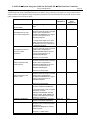
Note 2:
Exact control point calculation. The control point is set to a point on a line having the following equation:
nvoData.TempControlPt = nciOAReset.Setpoint + (X * A / B)
where
A = nciOAReset.MaxSetpoint – nciOAReset.Setpoint
Furthermore: A is limited to the 0 and 250 degrees C range before being used in the formula.
Normally the tool that enters values in nciOAReset does not cause the limit to be exceeded but
the limit protects the BIC from invalid values set by the tool.
B = nciOAReset.OaMaxSetpoint – nciOAReset.OaMinSetpoint
Furthermore: B is limited to the 1 to 140 degrees C range before being used in the formula
above. Normally the tool that enters values in nciOAReset does not cause the limit to be exceeded
but the limit protects the BIC from invalid values set by the tool.
X = nciOAReset.OaMaxSetpoint – nvoData.OutsideAirTemp
Furthermore: X is limited to the 0 to B degrees C range before being used in the formula above.
LonWorks System Integrator Guide for the Intelli-Fin Boiler Interface Controller
Version LOCH SIG-01
Page 26
If nvoData.OutsideAirTemp is greater than or equal to nciOAReset.OaMaxSetpoint, then X = 0
because of the limit and then the control point = nciOAReset.Setpoint.
If nvoData.OutsideAirTemp is less than or equal to nciOAReset.OaMinSetpoint, then X = B
because of the limit and then the control point = nciOAReset.MaxSetpoint.
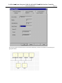
The equation is illustrated by the figure below:
Control Point Temperature
MaxSetpoint
Setpoint
OaAMinSetpoint
Outdoor Temperature
OaMaxSetpoint
BIC and CD Factory Set Configuration
********* WARNING !!!! *********
The BICs and CDs are configured at the factory. The system integrator must not change any of the
BIC or CD configurations.
The system integrator must protect the configuration of the BIC and CD made in the factory. During
installation, the system integrator must read the configuration parameters from the BICs into the tool
data base (LNS data base) before trying to monitor or change anything in the BICs.
Altering the BIC configuration parameter may introduce inappropriate or unsafe unit operation.
Furthermore the factory sets the network image (domain, subnet, node, and bindings) so that BICs
can communicate with one another and CDs can display BIC status. If you do not follow the
procedure given in the Step by Step Integration Procedure, and write the network image you could
cause the BICs and /or CDs to no longer communicate with one another.
********* WARNING !!!! *********
In all cases the BIC controller system and any optional command display modules are pre configured at the factory:
•
Each BIC and the command display are assigned unique addresses (domain, subnet, node)
•
Network image is pre loaded at the factory.
LonWorks System Integrator Guide for the Intelli-Fin Boiler Interface Controller
•
Version LOCH SIG-01
All of the configuration parameters are loaded at the factory.
Page 27
The command display module(s) are configured to communicate with the BICs using subnet / node addressing. Each
command display can support up to 17 BICs.
•
Typically only one BIC per interconnected group is configured to be a sequencer.
What is LNS?
The acronym LNS means LonWorks Network Services. LNS provides network services that are necessary to build
interoperable LonWorks systems or jobs. LNS resides in a device on the network (usually a PC but smaller versions are
available) and provides services to any client (device) that requests them. Typically LNS is used by human interface devices
(such as LonMaker) to manage the devices on the network. Specifically a human interface device may use the LNS server
when installing, configuring, interconnecting, commissioning, monitoring and replacing devices on the LonWorks network.
LNS does not display any network information directly. A separate user interface client (such as LonMaker) must be present
to display and modify anything on the network.
LNS assumes that each device on the network contains objects. Each object has inputs, outputs, configuration parameters, and
a predetermined fixed functionality. The objects may be configured and interconnected to perform desirable functions in the
system.
LNS keeps track of the devices and objects in the system data base. The LNS server makes the information in its data base
available to client devices such as human interfaces (like LonMaker) to perform their functions. Specifically, the LNS server
stores the following information:
•
Network interface information for each device type in the system. Specifies the object types and the data type
structure in each device type. For example: The BIC is a device type with two objects and several network variables
having specific data structures.
•
Names, addresses and type of device of all the devices in system
•
Configuration parameter values loaded into objects.
•
Connections between object inputs and outputs in the system.
•
Templates for each object type in a system. (Specifies inputs, outputs, configuration parameters, and default
configuration parameter values).
•
Additional template information to aid system design and monitoring.
The LNS server also performs the following functions at the request of a client:
•
Add device in the LNS data base. The device may not yet physically exist but has been added to the data base during
the design phase.
•
Retrieve the neuron id of a physical device and assign the neuron id to a device in the LNS data base
•
Commissions device. The commissioning process includes downloading the network address and binding
(connection) information, and the configuration parameter information to the device over the LonWorks network.
•
Add object and assign the object to a device in the LNS data base.
•
Add connections between object inputs and outputs in the LNS data base
•
Change the object configuration parameters in the LNS data base
•
Retrieve information from devices (objects) for use by monitor user interfaces.
LonWorks System Integrator Guide for the Intelli-Fin Boiler Interface Controller
Version LOCH SIG-01
Page 28
•
When object configuration parameters or connections are changed in the LNS data base, send the changes to the
device(s) that are already installed on the LonWorks network.
•
Retrieve network topology, network address, connections, configuration parameter information from a functioning
system and store the information in an LNS data base. Not all the desired information may reside in the system but
basic information can be retrieved.
•
Other functions to automate system design and maintenance.
The LNS server contains two major components. The Network Services Server (NSS) processes standard network services,
maintains the network data base and enables and coordinates multiple points of access to its services and data. The Network
Services Interface (NSI) provides the physical interface to the LonWorks network and manages transactions with the NSS and
application servers. In addition the NSS interfaces to local client applications through the LNS Host API. When the host is a
PC, then clients interface using Microsoft OLE automation.
The LNS architecture allows many human interfaces or tools to exist on the LonWorks network at the same time. Only one
Network Services Server (NSS) is allowed to exist in the network at a time. All tools and human interfaces are clients and
communicate with the NSS (via NSS and Host LNS API). The NSS coordinates the activities of the various clients and
ensures consistent information across all clients, the database, and the devices on the network.
Clients may have director (navigator), installation, maintenance, diagnostics, monitor, field programming, device specific
configuration, or job specific functions. Directors allow the user to choose the clients (and devices or objects) to display and
modify.
What is LonMaker?
LonMaker is an integration tool for designing, installing, maintaining, and operating a multi-vendor, open, interoperable
LonWorks network. Based on Echelon’s LNS network operating system, the LonMaker tool combines the client – server
architecture with an easy to use Microsoft Visio user interface. The result is a tool that is sophisticated enough to design and
commission a distributed control network but that can be left behind as an operations and maintenance tool. The LonMaker
tool takes full advantage of LonMark features such as standard functional profiles, configuration properties, and resource files.
LonWorks System Integrator Guide for the Intelli-Fin Boiler Interface Controller
Version LOCH SIG-01
Page 29
Users are provided with a familiar, CAD-like environment for designing a control system. LonMaker includes a number of
smart shapes for LonWorks networks, and users can create new custom shapes. Shapes may be single device, functional
block, or connection. Custom shapes may be a complete subsystem with nested subsystems and predefined devices,
functional blocks, and connections between them. Using custom subsystem shapes, additional subsystems can be created by
simply dragging a custom subsystem shape from a stencil to the drawing.
LonMaker performs the following functions with the aid of the behind the scenes LNS data base and the VISIO user interface:
• Installation of devices using service pin, bar code scanning, winking, manual entry, or automatic discovery
• Recover network design from an existing network
• Merge networks into one integrated system
• Test a device
• Configure of a device
• Manual operation of a device
• Browse a device or a functional block
• Display and allow users to change any network variable(s) in any device
• Compatible with LNS DDE server for a variety of third-party operator interface packages
• Supports multiple users
• Supports Plug-ins (custom user interfaces for specific device types or specific functions)
What is needed for system integration?
The following items are needed to integrate the BIC into an LNS based system.
•
Either LNS version 3.xx or LonMaker version 3.xx installed on your PC. LNS and LonMaker are Echelon products.
•
Network interface to connect your PC to the LonWorks network. Any of the NSI supported interfaces may be used
for system integration. Generally network interfaces are available from Echelon.
•
Resource files available in BIC. ZIP archive. BIC.ZIP is available from Lochinvar.
9 BIC.XIF – device interface
9 BIC.XFO and BIC.XFB – binary device interface files
9 BIC.DEF – source definition resource file
9 BIC.TYP – custom data structures
9 BIC.FPT – functional profile for BIC
9 BIC.ENU – United States English language text strings
9 BICUS.FMT– data format with United States units
9 BICSI.FMT – data format with metric units
9 README.TXT – instructions for resource files installation into LonMaker / LNS – It is recommended that you
read the README.TXT file for details on the installation of the resource files. There may be current issues with
LonMaker / LNS that you should know.
•
WinZip or other program that can extract the resource files from the BIC.ZIP archive and place them in the
appropriate directories.
•
You will need a browser to display and modify BIC information. LonMaker comes with a browser that shows the
values and allows you to change those that can be changed, but the format is not user friendly. Your custom browser
or graphics package can display the BIC information in a more user friendly format.
Step by step integration
The details of how to integrate a BIC system into a LonMaker system are presented below. The general steps are:
Ordering and Unit Installation Task
• Order the units per the usual Lochinvar ordering process.
• Install the units
System Integrator Task - Add BIC system to building network (Offnet)
Note: This task should be done at the office without being connected to the LonWorks network.
LonWorks System Integrator Guide for the Intelli-Fin Boiler Interface Controller
Version LOCH SIG-01
• Install the resource files into the appropriate directories
• Register the resource files in the resource catalog
• Back up any existing network before making any major changes to an existing network.
• Add BICs (sequencer and units) and dummy CDs to either a new or existing LNS network
• Configure the LNS data base so that the BIC uses a device specific resource file
• Add boiler function blocks (objects) for the sequencer and each of the units to the network
• Bind the Sequencer BIC to the Unit BICs for normal sequencer operation
• Order replacement CDs
• Make custom graphical user interfaces to display system status
Note: Do not add or delete BICs from the network after ordering replacement CDs.
Page 30
Reprogramming CDs Task
• Using information provided by System Integrator, the Lochinvar factory programs replacement CDs with the new
subnet/node address of the BICs, and ships them to the system integrator.
Prepare to connect LonWorks Network wire to the BIC System Task
• Run the building LonWorks network wire to the BIC system but do not connect the BIC system to building
LonWorks network.
System Integrator Task – Final Integration (OnNet)
Note: The final task of integration is performed after replacement CDs arrive.
• Shut down the boiler system
• Remove the CDs from the boiler system
• Connect the BIC System to the building LonWorks Network
• Commission the BICs
• Install the replacement CDs
• Return the boiler system to operation
• Test any network functions
The step by step process is long, involved, and somewhat tedious. Do not rush through the process, or skip any steps. Check
your work before you go on to the next step. Refer to this step by step guide on every step.
It is not recommended that you use the LonMaker network recovery and merge facilities with BICs or CDs. The recovery
process is prone to recovery errors and can leave the BICs in a non-functional state. For example: The recovery process
does not recover BIC bindings completely and the merge facility changes the subnet / node address of all the BICs.
After the BICs have been integrated into a system it is recommended that the LonMaker merge facility not be used on the
network. The CDs contain a table of BIC subnet / node addresses and if the merge facility changes a BICs subnet / node
address, the CD will no longer be able communicate with BICs.
Ordering and Unit Installation Task
Order the units using the standard Lochinvar ordering process. Install and connect the units into a boiler (heater) system
interconnecting the BICs and CDs with a LonWorks network. Turn on and test the system. The system should be working
before it is integrated into the rest of the building automation system.
System Integrator Task - Add BIC system to building network (Offnet)
The steps in this task should be done at the office by the system integrator without being connected to the LonWorks network.
At the end of this task, the BICs and CDs have been added to the network data base but the units are still running as a non
integrated subsystem. This task takes a skilled person about 30 minutes (not including custom graphics). Do not add or
delete BICs from the network after ordering replacement CDs.
Install the resource files into the appropriate directories
Extract the resource files from the BIC.ZIP archive and install them into the directories shown below.
LonWorks System Integrator Guide for the Intelli-Fin Boiler Interface Controller
File
BIC.XIF
BIC.XFB
BIC.XFO
BIC.TYP
BIC.ENU
BIC.FPT
BicUS.fmt
BicSI.fmt
Version LOCH SIG-01
Directory (note 1)
Comments
\LonWorks\import\Lochinvar\Bic
\LonWorks\import\Lochinvar\Bic
\LonWorks\import\Lochinvar\Bic
\LonWorks\types\User\Lochinvar\Bic
\LonWorks\types\User\Lochinvar\Bic
\LonWorks\types\User\Lochinvar\Bic
\LonWorks\types\User\Lochinvar\Bic
Note 2
\LonWorks\types\User\Lochinvar\Bic
Note 2
Page 31
Note 1: Directory path names are typical. It is assumed that the default LonMaker directory scheme is in use.
Note 2: BicUS.fmt is for U.S. default units. BicSI.fmt is for metric units. Copy either BicUS.fmt or BicSI.fmt to the type
directory as required by your regional use of units.
Register the resource files in the resource catalog
It is assumed that the LNS user is able to use the resource catalog facility (ldrfcat.exe) and no other instructions are given
here.
Back up any existing network before making any major changes to an existing network
If, the BICs will be connected to an existing network, backup the network using the LonMaker back up facility. In case there
is a fatal error made, you will be able to recover using this backup.
LonWorks System Integrator Guide for the Intelli-Fin Boiler Interface Controller
Version LOCH SIG-01
Page 32
Add BICs (sequencer and units) and dummy CDs to either a new or existing LNS network
In this step you will create devices in the network for your BICs and CDs. CDs will not be commissioned under LNS but their
subnet / node address must be “reserved”. By creating dummy CDs, their address will be reserved. For every CD, create an
extra BIC and give it the name of a CD.
If there is more than one group in the network create one group of units at a time. For example, a group is one sequencer,
several units, and one CD.
•
Start LonMaker and either create a new network or open an existing network. You should have backed up an
existing network in the previous step. You should not check the OnNet Radio Button in the Network Open Wizard.
Work should be done without communicating the changes to the any nodes at this time.
•
Drag a Device template onto the drawing which launches the “New Device Wizard”. Give the device a name such as
BOILER 01, and create one device for every BIC (sequencer and units) and one device for every CD. In this case
there are 6 devices. Do not commission the devices at this time. Go to the next step.
LonWorks System Integrator Guide for the Intelli-Fin Boiler Interface Controller
Version LOCH SIG-01
•
Page 33
Load the BIC.XIF file for all the devices, and proceed through the other wizard screens with the default values.
The XIF file should not be Uploaded from the device. Some device versions may not have up to date self
documentation. Ignore the “Configuration Properties Warning” if it appears. Assign the devices to the channel
that will be used to connect the boiler system to the network. “Finish the New Device Wizard”.
LonWorks System Integrator Guide for the Intelli-Fin Boiler Interface Controller
•
Version LOCH SIG-01
Page 34
On the drawing, select (click) each device, and open the “Device Properties” dialog box by selecting properties
from the drop down menu. Change the name of each device to an appropriate name. The order of the names is
not important at this time. The Device Name given in “Device Properties” will appear on the drawing, is saved
in the LNS data base, and may be used on custom graphics. The names will not appear on the CD. The CD will
display the names given during configuration at the factory. The names displayed by CD are saved in each BIC.
The names saved in BICs may be changed by Intelli-Station.
Select the “Device Properties” Identifiers tab and note what subnet/ node ID has been assigned to the device.
Make a list of devices containing,: “CD Name”(named displayed by CD); “Device Name” (from LNS data base
– Device Properties dialog); Subnet, Node, Neuron Id, and Device Type. An example of a list of devices is
shown below. Enter this information on the REPLACEMNT CD ORDER FORM found a few pages later in
this book and as a separate file bundled with this document in electronic form. The Neuron Id can be found on
the bar code labels of the units.
Example device list compiled from the CD bar code labels, and the Device Properties dialog box. This list is used to
order replacement CDs custom loaded for your network.
CD Name (Given at
Lochinvar Factory)
SEQUENCER
BOILER01
BOILER02
BOILER03
CD01
CD02
LNS Device Name
(Given by System
Integrator)
SEQUENCER
Boiler01
Boiler02
Boiler03
CD1
CD2
LNS
Subnet
LNS
Node
NeuronID
Node Type
3
3
3
3
3
3
25
26
27
28
29
30
010031F24E00
010031F20C00
010029B81200
010029B91900
010053EEDE00
010038C92D00
BIC
BIC
BIC
BIC
Command Display
Command Display
LonWorks System Integrator Guide for the Intelli-Fin Boiler Interface Controller
Version LOCH SIG-01
Page 35
The drawing should look like this when all of the BICs and dummy CDs have been added to network and given
appropriate names.
LonWorks System Integrator Guide for the Intelli-Fin Boiler Interface Controller
Version LOCH SIG-01
Page 36
Configure the LNS data base so that the BIC uses a device specific resource file
There is a bug in LonMaker/LNS that causes all user defined objects to be assigned to LonMark resource file scope 3 resource
files (one resource file for each manufacturer) by default. For large organizations it is impractical to have one resource file
for all node types. For large organizations it is more convenient to use resource file scope 6 (one resource file for each node
type). Furthermore LonMaker does not currently search for resource file by scope. LonMark envisions that tools search for
resource files starting with scope 6 and proceeding to scope 5, the scope 4, etc until profiles, data types, and formats are found
in a resource file. LonMaker does allow the scope of each object to be changed manually using the LNS Object Browser
(LNSObjectBrowser.exe). See the “LonMark Resource File Developer’s Guide” and “LonMark Application Layer
Interoperability Guidelines” for more detailed information on “Scope”.
In some future version (hopefully a service pack or minor version update) of LNS/LonMaker, this bug may be fixed and the
step given below will then not be necessary.
The procedure below changes the resource file “Scope” of all installed devices using the BIC resource files, providing no
function blocks (objects) have yet been created on a drawing.
•
Exit LonMaker (to avoid conflicts between LonMaker and the LNS Object Browser).
•
Start the LNS Object Browser. This program comes with LNS and LonMaker and allows a skilled person to change
certain parameters in the LNS data base.
•
Navigate the tree as shown in the tree below and also depicted in the screens below:
ObjectServer
Networks
<NetworkName> for example: ExampleA
Systems
<SystemName> often the same as the Network Name, For example: ExampleA
TemplateLibrary
DeviceTemplates
BIC
Interface
LonMarkObjects
<ObjectTypeName> may be LMOBJ or BoilerObject or similar
LonWorks System Integrator Guide for the Intelli-Fin Boiler Interface Controller
Version LOCH SIG-01
Page 37
LonWorks System Integrator Guide for the Intelli-Fin Boiler Interface Controller
Version LOCH SIG-01
Page 38
•
From the LNS Object Browser menu, first elect "Options" and then select "Allow Modifications". Then double click
on Mode in the right window. The dialog box below appears. Enter 6 in the “New Value’ box and click on “OK”
•
Exit the LNS Object Browser. Now the “Scope” of all the boiler objects that will be created later is 6 and matches
the resource files.
LonWorks System Integrator Guide for the Intelli-Fin Boiler Interface Controller
Version LOCH SIG-01
Page 39
Add boiler function blocks (objects) for the sequencer and each of the units to the network
Connections between the sequencer and units must be added to the network. In LonMaker the connections are made between
functional block objects. Boiler Objects (LMOBJ1) must be added to the drawing before the connections (binding) can be
made. The steps below show how to add objects to the drawing.
•
Drag the “Functional Block” template to the drawing, causing the “New Functional Block Wizard” to run. Select
the device Name and Functional Block Name (LMOBJ1) to be added to the drawing.
Note: For BICs the ID is 6:20040. 6 is the resource file scope and 20040 is the resource file user defined object type that
has been assigned to BICs. If the scope is not 6, the resource file will not be found by LNS and device data will not be
parsed and formatted correctly in the LonMaker browser and other user interfaces that use LNS resource files. If the
scope is not 6, the scope can be changed manually for every BIC - LMOBJ1 using the LNS Object Browser.
LonWorks System Integrator Guide for the Intelli-Fin Boiler Interface Controller
•
Version LOCH SIG-01
Page 40
Give the Functional Block (FB) a meaningful name. Press Finished to place the object on the drawing. Repeat for
all the BICs. Do not make any functional blocks for the CDs.
LonWorks System Integrator Guide for the Intelli-Fin Boiler Interface Controller
Version LOCH SIG-01
Page 41
Bind the Sequencer BIC to the Unit BICs for normal sequencer operation
The variables nvoSeqShare, nviSeqShare, nvoModBoilrShare and nviModBoilrShare, are used to share information between
the sequencer BIC and the unit BICs. Specifically the SEQUENCER uses nvoSeqShare connected (bound) to the UNITS
nviSeqShare to request and modulate unit heat. Feedback from the UNITS nvoModBoilrShare connected (bound) to the
SEQUENCER nviModBoilrShare reports the actual unit response to the request. Note: If there is no sequencer, then there is
no binding required.
•
In LonMaker, on the drawing, select the sequencer BIC function block. Right Click and select “Connect” from
the drop down menu.
•
Before making any connections select “Unacknowledged” in the “New Connections” drop down box.
•
Then make the following two connections with the Hub and Targets and “Add” them as listed below:
Hub
SEQUENCER -> nvoSeqShare
Target(s)
All UnitBIC -> nviSeqShare
SEQUENCER -> nviModBoilrShare
All UnitBIC -> nvoModBoilrShare
Hub selection
Note
Do not include SEQUENCER in
the target List
Do not include SEQUENCER in
the target list
LonWorks System Integrator Guide for the Intelli-Fin Boiler Interface Controller
Version LOCH SIG-01
Page 42
Use the Add FB/SN button to add target devices to the list of targets. Then use Add All to simplify adding targets.
The view below shows target selection and final results.
Sometimes, the wizard tries to connect between a sequencer input and output network variable. Be sure to delete the
connection between the sequencer input and output network variables, by first selecting the sequencer to sequencer
connection in the Connections window and then pressing the delete button.
LonWorks System Integrator Guide for the Intelli-Fin Boiler Interface Controller
Version LOCH SIG-01
The drawing should look like this when objects and connections have been added.
Page 43
LonWorks System Integrator Guide for the Intelli-Fin Boiler Interface Controller
Version LOCH SIG-01
Page 44
Order replacement CDs
Request replacement CDs from Lochinvar using the REPLACEMNT CD ORDER FORM shown below. The
REPLACEMENT CD ORDER FORM is also included in a separate file. It is preferred that you fill out the form
electronically and send it to Lochinvar as an electronic file.
The form includes a space for the network domain. The network domain can be found in a tab under LonMaker Network
Properties (activated from the LonMaker Properties menu item). The domain length must be one byte long.
********* CRITICAL INFORMATION !!!! *********
The BICs and CDs are configured at the factory. The factory sets the network image (domain,
subnet, node, and bindings) so that BICs can communicate with one another and CDs can display BIC
status.
Integration into an LNS system changes the BIC network image to one that has been created for your
network during the task of adding BICs to the building network.
Replacement CDs will be programmed according to the subnet node address listed in the
REPLACEMNT CD ORDER FORM. It is important to send the correct information to the factory.
********* CRITICAL INFORMATION!!!! *********
LonWorks System Integrator Guide for the Intelli-Fin Boiler Interface Controller
Version LOCH SIG-01
Page 45
REPLACEMNT CD ORDER FORM
SITE (where BICs will be installed): ______________________________________________
CUSTOMER:
Company:_____________________________________________
Contact:_______________________________________________
Phone:_________________________________________________
FAX:__________________________________________________
E-Mail:_________________________________________________
SHIPPING ADDRESS:
Address:______________________________________________________
______________________________________________________
City, State, Zip:_________________________________________________
Country:_______________________________________________________
DOMAIN:
______ Hexadecimal (only one byte domain lengths are allowed)
CD Name (Given at
Lochinvar Factory)
SEQUENCER
BOILER01
BOILER02
BOILER03
BOILER04
BOILER05
BOILER06
BOILER07
BOILER08
BOILER09
BOILER10
BOILER11
BOILER12
BOILER13
BOILER14
BOILER15
BOILER16
CD01
CD02
CD03
CD04
LNS Device Name (Given
by System Integrator)
LNS
Subnet
LNS
Node
NeuronID
Don’t Care
Don’t Care
Don’t Care
Don’t Care
Node Type
BIC - Sequencer
BIC
BIC
BIC
BIC
BIC
BIC
BIC
BIC
BIC
BIC
BIC
BIC
BIC
BIC
BIC
BIC
Command Display
Command Display
Command Display
Command Display
Note: It is expected that the CDs will display all boilers in this group and that the CD passwords are the default values. If this
is not the case, specify which CDs should display which BICs and list the level 1, level 2, and level 3 passwords on the next
page.
LonWorks System Integrator Guide for the Intelli-Fin Boiler Interface Controller
Version LOCH SIG-01
Page 46
Make custom graphical user interfaces to display system status
Graphical user interfaces can be created to display any of the parameters listed in the BIC details section. It is the business of
system integrators to provide workstations with custom graphics. Only the items listed in BIC details may be displayed and /or
changed by custom graphic user interfaces.
Reprogramming CDs Task
Using the REPLACEMENT CD form, the Lochinvar factory programs replacement CDs with the new subnet/node address of
the BICs, and ships them to the system integrator. Lochinvar will ship a copy of the REPLACEMNT CD ORDER FORM
with the CDs so you will have a list of the devices and their neuron ids available during the final integration task.
Prepare to connect LonWorks Network wire to the BIC System Task
At the site, run the building LonWorks network wire to the BIC system but do not connect the LonWorks bus to the BIC
system. This task can be performed at any time. Use the standard LonWorks bus wire and LonWorks topology to include the
BIC system in the building automation system.
See “Junction Box and Wiring Guideline for Twisted Pair LonWorks Networks” by Echelon Corporation for more
information on the standard wiring LonWorks bus wiring practices.
System Integrator Task – Final Integration (OnNet)
In a previous task, a network containing the BICs and CDs were created. Since CDs cannot presently be programmed by LNS
tools, the replacement CDs where programmed at the Lochinvar factory. When the replacement CDs arrive, the final
integration task can be completed.
Before starting the final integration task, it must be pointed out that the boiler system is now working. It is possible, through
error, to cause the boiler system to no longer function. Follow the warnings given below.
Shut down the boiler system
Shut down the boiler system by placing all the RUN / STOP switches in the STOP position.
Remove the CDs from the system
The CDs are mounted on the units using a sub base. A CD can be removed by lifting the bottom of the CD away from the sub
base. When the bottom of the CD is disconnected from the sub base, rotate the CD further until the plastic tabs at the top of
the CD allow the CD to be removed from the sub base.
Package the removed CDs for return to the Lochinvar factory.
Connect the BIC System to the building LonWorks Network
Connect the LonWorks network to the building network. LonMaker / LNS must be connected to the LonWorks network to
complete this installation. LonMaker must be able to communicate with the BICs.
LonWorks System Integrator Guide for the Intelli-Fin Boiler Interface Controller
Version LOCH SIG-01
Page 47
Commission the BICs
In this step the BICs will be commissioned. The process of commissioning is a three step process.
• Assign the neuron id to a device in the network drawing.
• LonMaker reads the configuration parameters from the device
• LonMaker down loads the network image to the device
CDs are not commissioned by LNS / LonMaker. Do not try to commission CDs.
********* WARNING !!!! *********
The BICs and CDs are configured at the factory. The system integrator must not change any of the
BIC or CD configurations.
The system integrator must protect the configuration of the BIC and CD made in the factory. During
installation, the system integrator must read the configuration parameters from the BICs into the tool
data base (LNS data base) before trying to monitor or change anything in the BICs.
Failure to read the configuration parameters from the BICs will allow LonMaker to set the
configuration parameters to incorrect values. The BIC system will no longer function properly.
The mistake of writing configuration parameters instead of reading configuration parameters is not
easily recovered.
********* WARNING !!!! *********
•
Start LonMaker and open the network. Check the OnNet Radio Button in the Network Open Wizard. In this
step LonMaker will communicate with device on the LonWorks network.
•
On the network drawing, select all the BICs to be commissioned. Do not select any CDs.
LonWorks System Integrator Guide for the Intelli-Fin Boiler Interface Controller
•
Version LOCH SIG-01
Page 48
Right click the selected device(s) to display the drop down menu. From the drop down menu , select
Commission to launch the Commission Device Wizard. There is no application image to load. Next step.
LonWorks System Integrator Guide for the Intelli-Fin Boiler Interface Controller
Version LOCH SIG-01
•
Page 49
Select the following :
State = OnLine
Source of Configuration Property Values = Current values in device
********* WARNING !!!! *********
THIS IS A CRITICAL STEP.
“OnLine” and “Current Values In Device” must be selected.
Failure to select these items will result in a non-functioning BIC system and you cannot recover the
system without outside help.
********* WARNING!!!! *********
********* CHECK YOUR WORK!!!! *********
“OnLine” and “Current Values In Device” must be selected.
********* CHECK YOUR WORK!!!! *********
•
Next Step
LonWorks System Integrator Guide for the Intelli-Fin Boiler Interface Controller
•
Version LOCH SIG-01
Page 50
The Manual method of Device Identification is preferred . Typically the LNS workstation is not located near the
units, it may be easier and more accurate to manually enter the neuron ids. If you do use the service pin method,
the service pin button is on one side of the BICs. Next Step.
LonWorks System Integrator Guide for the Intelli-Fin Boiler Interface Controller
•
Version LOCH SIG-01
Page 51
Enter the neuron ids of the BICs from a copy of the REPLACEMNT CD ORDER FORM. Finish. During this
step, the BICs will be loaded with an updated network image (domain / subnet / node address and the bindings)
you have created for this project.
********* WARNING!!!! *********
Failure to match the Neuron Id with the correct BIC, will require that you delete the function blocks
and bindings from your project, rename the BICs according to the correct name for each neuron id,
and create function blocks and bindings again.
DO NOT DE-COMMISION BICs
DE-COMMISIONING RESETS CONFIGURATION PARAMETERS
and the factory set parameters will be lost.
In addition, De-Commissioning sets the node offline, and the BIC no longer will control a UNIT.
********* WARNING!!!! *********
LonWorks System Integrator Guide for the Intelli-Fin Boiler Interface Controller
•
Version LOCH SIG-01
The look of commissioned BICs. Do not commission CDs
Page 52
Install the replacement CDs
Install the replacement CDs on their sub bases. Line up the upper tabs first and gently rotate the CD onto the connections at
the bottom. After a few minutes, the CDs should be displaying BIC status.
Return the boiler system to operation
Set all the RUN/STOP switches to RUN. Create a demand for heat. The units should stage on (BURNER ON) one at a time
over a period of several minutes between units. It may be difficult to create enough demand in a large system and mild
weather so that all units stage on (BURNER ON). If the temperature is especially mild, the outside air lock out temperature
may prevent any units from staging on.
Comment: Intell- Station can be useful during this integration process if the last step fails. Also an on site SLTA and
modem can be used to restore the BICs to a functioning boiler system. The Lochinvar factory can restore the BIC to the
original condition if the integration effort fails.
Test any network functions
Test any graphical user interfaces you have created to display or control BICs.
LonWorks System Integrator Guide for the Intelli-Fin Boiler Interface Controller
Version LOCH SIG-01
Page 53
Appendix A – Network variable description
********* WARNING !!!! *********
The BIC contains network variables and configuration parameters other than the ones described here.
The system integrator should not attempt to bind to the unspecified network variables or attempt to
change them since some of the network variables may present safety issues, except as specified in the
section on binding between the sequencer and unit BICs.
********* WARNING !!!! *********
The LonMark XIF and resource files for BICs includes machine readable definitions of the exposed network variables. For
systems that do not read LonMark files, a detailed description of the exposed network variables is given below for manual
entry into non-LNS systems.
The following BIC network variables are available for use by system integrators. The BIC contains other network variables,
but they are intended for communications between sequencer and units, factory configuration, or for future enhancements.
Changing or binding to network variables that are not described below could cause safety problems and therefore the system
integrator should not attempt to change the unspecified network variables or bind to the unspecified network variables.
Network variable
name
(NvName)
nviRequest
noStatus
nroPgmVer
NvIndex
nvoData
nciConfigSr
nciOAReset
nvoIO
Class
Mechanism
Data Structure
SNVT
type
0
1
19
IN
in
OUT
out
CONST polled
SNVT_obj_request
SNVT_obj_status
UNVT_pgm_id
92
93
0
27
37
38
40
OUT
CONFIG
CONFIG
OUT
UNVT_ctl_data
SNVT_config_src
UNVT_oa_reset
UNVT_io
0
69
0
0
polled
in
in
polled
Comment
Node object – request
Node object – status
The node_type field is used by some tools to identify
the fact that this node is a BIC.
Node object – Network image self configuration flag
Where:
•
NvName is the assigned name of the network variable.
•
NvIndex is the assigned network variable index of the network variable.
Class:
Class
CONST
CONFIG
OUT
IN
Node Stores This Variable In
(P)ROM
EEPROM (EEPROM life is limited to 10K writes and
should not be written frequently
RAM
RAM
Direction From / To Node
Output
Input
Output
Input
Mechanisms:
Mechanism
Out
In
polled
Full meaning
Output
Input
Polled output
•
Data Structure: The data structure specifies the fields of the network variable. See the definitions given below:
•
SNVT type is the standard network variable type number assigned to this network variable type by LonMark
LonWorks System Integrator Guide for the Intelli-Fin Boiler Interface Controller
Version LOCH SIG-01
Page 54
Some of the network variables are data structures having several fields or pieces of data in them. The network variable fields
are shown below.
NvName
nviRequest
nviRequest
nvoStatus
nvoStatus
nvoStatus
nvoStatus
nvoStatus
nvoStatus
nvoStatus
nvoStatus
nvoStatus
nvoStatus
nvoStatus
nvoStatus
nvoStatus
nvoStatus
nvoStatus
nvoStatus
nvoStatus
nvoStatus
nvoStatus
nvoStatus
nvoStatus
nvoStatus
nvoStatus
nvoStatus
nvoStatus
nvoStatus
nroPgmVer
nroPgmVer
nroPgmVer
nroPgmVer
nroPgmVer
nroPgmVer
nroPgmVer
nroPgmVer
nroPgmVer
nvoData
nvoData
nvoData
nvoData
nvoData
nvoData
nvoData
nvoData
nvoData
nvoData
nvoData
nvoData
nvoData
nvoData
nvoData
nvoData
nvoData
nvoData
nvoData
nvoData
nvoData
nvoData
nvoData
nvoData
nvoData
nvoData
NvField
Field
Units
Number
object_id
1
object_request
2
object_id
1
invalid_id
2
invalid_request
3
disabled
4
out_of_limits
5
open_circuit
6
out_of_service
7
mechanical_fault
8
feedback_failure
9
over_range
10
under_range
11
electrical_fault
12
unable_to_measure
13
comm_failure
14
fail_self_test
15
self_test_in_progress
16
locked_out
17
manual_control
18
in_alarm
19
in_override
20
report_mask
21
programming_mode
22
programming_fail
23
alarm_notify_disabled
24
reserved1
25
reserved2
26
reserved1
1
reserved2
2
reserved3
3
reserved4
4
reserved5
5
reserved6
6
reserved7
7
reserved6
8
node_type
9
Mode
1
EffectOcc
2
OverRideOcc
3
SchedOcc
4
ManualOcc
5
SensorOcc
6
TempControlPt
7
deg C
InletWaterTemp
8
deg C
OutletWaterTemp
9
deg C
DeltaTemp
10
DD C
CalcWaterFlow
11
liter/sec
BypassTemp
12
deg C
OutsideAirTemp
13
deg C
VFDPos
14
percent
HeatStages
15
PrimaryPmp
16
SecondaryPmp
17
IgnitEnab
18
LocalAlarm
19
DialOutAlarm
20
AuxCallHeat
21
Out7
22
SeqControllerCfg
23
ManDisableIn
24
GlowBarOnIn
25
GasValveOnIn
26
C-Software Data
Type
unsigned long
object_request_t
unsigned long
unsigned :1
unsigned :1
unsigned :1
unsigned :1
unsigned :1
unsigned :1
unsigned :1
unsigned :1
unsigned :1
unsigned :1
unsigned :1
unsigned :1
unsigned :1
unsigned :1
unsigned :1
unsigned :1
unsigned :1
unsigned :1
unsigned :1
unsigned :1
unsigned :1
unsigned :1
unsigned :1
unsigned :1
unsigned :8
char
char
char
char
unsigned short
unsigned short
unsigned short
unsigned short
unsigned short
stmd_type
SNVT_occupancy
SNVT_occupancy
SNVT_occupancy
SNVT_occupancy
SNVT_occupancy
SNVT_temp_p
SNVT_temp_p
SNVT_temp_p
SNVT_temp_p
SNVT_flow
SNVT_temp_p
SNVT_temp_p
SNVT_lev_percent
unsigned short
unsigned :1
unsigned :1
unsigned :1
unsigned :1
unsigned :1
unsigned :1
unsigned :1
unsigned :1
unsigned :1
unsigned :1
unsigned :1
SNVT
type
109
109
109
109
109
105
105
105
105
15
105
105
81
Display Data Type ByteOffset
UNSIGNED
0
object_request_t
2
UNSIGNED
0
&BOOLEAN
2
&BOOLEAN
2
&BOOLEAN
2
&BOOLEAN
2
&BOOLEAN
2
&BOOLEAN
2
&BOOLEAN
2
&BOOLEAN
2
&BOOLEAN
3
&BOOLEAN
3
&BOOLEAN
3
&BOOLEAN
3
&BOOLEAN
3
&BOOLEAN
3
&BOOLEAN
3
&BOOLEAN
3
&BOOLEAN
4
&BOOLEAN
4
&BOOLEAN
4
&BOOLEAN
4
&BOOLEAN
4
&BOOLEAN
4
&BOOLEAN
4
&BOOLEAN
4
UNSIGNED
5
UNSIGNED
0
UNSIGNED
1
UNSIGNED
2
UNSIGNED
3
UNSIGNED
4
UNSIGNED
4
UNSIGNED
5
UNSIGNED
6
UNSIGNED
7
stmd_type
0
SNVT_occupancy 1
SNVT_occupancy 2
SNVT_occupancy 3
SNVT_occupancy 4
SNVT_occupancy 5
SIGNED
6
SIGNED
8
SIGNED
10
SIGNED
12
UNSIGNED
14
SIGNED
16
SIGNED
18
SIGNED
20
UNSIGNED
22
&BOOLEAN
23
&BOOLEAN
23
&BOOLEAN
23
&BOOLEAN
23
&BOOLEAN
23
&BOOLEAN
23
&BOOLEAN
23
&BOOLEAN
23
&BOOLEAN
24
&BOOLEAN
24
&BOOLEAN
24
BitOffset
0
0
0
7
6
5
4
3
2
1
0
7
6
5
4
3
2
1
0
7
6
5
4
3
2
1
0
0
0
0
0
0
0
0
0
0
0
0
0
0
0
0
0
0
0
0
0
0
0
0
0
0
7
6
5
4
3
2
1
0
7
6
5
Len
gth
2
1
2
1
1
1
1
1
1
1
1
1
1
1
1
1
1
1
1
1
1
1
1
1
1
1
1
1
1
1
1
1
1
1
1
1
1
1
1
1
1
1
1
2
2
2
2
2
2
2
2
1
1
1
1
1
1
1
1
1
1
1
1
Scal Scale
e10 Offset
1
0
1
0
1
0
1
0
1
0
1
0
1
0
1
0
1
0
1
0
1
0
1
0
1
0
1
0
1
0
1
0
1
0
1
0
1
0
1
0
1
0
1
0
1
0
1
0
1
0
1
0
1
0
1
0
1
0
1
0
1
0
1
0
1
0
1
0
1
0
1
0
1
0
1
0
1
0
1
0
1
0
1
0
1
0
.01 0
.01 0
.01 0
.01 0
1
0
.01 0
.01 0
.005 0
1
0
1
0
1
0
1
0
1
0
1
0
1
0
1
0
1
0
1
0
1
0
1
0
LonWorks System Integrator Guide for the Intelli-Fin Boiler Interface Controller
Version LOCH SIG-01
NvName
nvoData
nvoData
nvoData
nvoData
nvoData
nvoData
nvoData
nvoData
nvoData
nvoData
nciConfigSrc
nciOAReset
nciOAReset
nciOAReset
nciOAReset
nciOAReset
nciOAReset
nciOAReset
nciOAReset
nciOAReset
nvoIO
NvField
LowWaterFlowIn
FlameFailIn
LowAirIn
BlockDrainIn
LowGasIn
BlockFlueIn
LEDOut
Spare
ModeTimer
BypassPos
MaxSetpoint
SetbackAmt
Setpoint
EmergSetpoint
OaMinSetpoint
OaMaxSetpoint
OaHtgLockout
AbsMaxSetp
AbsMinSetp
BlrTotRtHr
Field
Units C-Software Data
Number
Type
27
unsigned :1
28
unsigned :1
29
unsigned :1
30
unsigned :1
31
unsigned :1
32
unsigned :1
33
unsigned :1
34
unsigned :6
35
seconds unsigned long
36
percent SNVT_lev_percent
SNVT_config_src
1
deg C SNVT_temp_p
2
deg C SNVT_temp_p
3
deg C SNVT_temp_p
4
deg C SNVT_temp_p
5
deg C SNVT_temp_p
6
deg C SNVT_temp_p
7
deg C SNVT_temp_p
8
deg C SNVT_temp_p
9
deg C SNVT_temp_p
hour
unsigned long
SNVT
type
81
69
105
105
105
105
105
105
105
105
105
Page 55
Display Data Type ByteOffset
&BOOLEAN
24
&BOOLEAN
24
&BOOLEAN
24
&BOOLEAN
24
&BOOLEAN
24
&BOOLEAN
25
&BOOLEAN
25
UNSIGNED
25
UNSIGNED
26
SIGNED
28
config_source_t
0
SIGNED
0
SIGNED
2
SIGNED
4
SIGNED
6
SIGNED
8
SIGNED
10
SIGNED
12
SIGNED
14
SIGNED
16
UNSIGNED
15
BitOffset
4
3
2
1
0
7
6
0
0
0
0
0
0
0
0
0
0
0
0
0
0
Len
gth
1
1
1
1
1
1
1
6
2
2
1
2
2
2
2
2
2
2
2
2
2
Scal Scale
e10 Offset
1
0
1
0
1
0
1
0
1
0
1
0
1
0
1
0
1
0
.005 0
1
0
0.01 0
0.01 0
0.01 0
0.01 0
0.01 0
0.01 0
0.01 0
0.01 0
0.01 0
1
0
Where the table headings and the information in the columns are shown below:
• NvName: The network variable name
• NvField: The name of the field for network variable NvName.
• Field Number: Field number for those tools that count fields from the beginning of the data string communicated to
or from the device. This number is based on the information in the XIF file.
• Units: The engineering units of the field as displayed by an operator interface when the scale factors given below are
used.
• Software Data Type is the way the field is declared in the software code (Neuron-C).
• SNVT type is the standard network variable type number assigned by the LonMark to this field
• Display Data Type:
DataType
SIGNED
UNSIGNED
FLOAT
ASCII
HEX
BIT
&other
other
Comments
Signed Analog Value
Unsigned Analog Value
Floating point
Text
Hexadecimal Value
Bit Field
Enumerated value based on a bit
fields
Enumerated value based on a byte
BitOffset Column
Don't Care
Don’t Care
Don’t Care
Don’t Care
Don’t Care
First Bit in the field
First Bit in the field
Length Column
Number of Bytes
Number of Bytes
Number of Bytes
Number of Bytes
Number of Bytes
Number of Bits
Number of Bits
Don’t Care
Number of Bytes (must be
one)
Note: "other" is any word combination referring to an enumerated type name. For example if DataType is
“ENUM_TYPE", the data is an enumerated type whose values are listed under EnumType ENUM_TYPE.
•
•
•
•
ByteOffset: This parameter locates the beginning of the field in the network variable and specifies the first byte of
the field. The first data byte sent or received in a network variable is number "0". The second byte is byte "1", etc.
For example, if ByteOffset is 10, then the first byte of the field is the eleventh byte sent or received.
BitOffset: When the DataType is "BIT" or "&other", this parameter locates the first bit in a bit field. The least
significant bit of the field, where 0 is the least significant bit of the byte. Bit fields are not allowed to go over a byte
boundary.
Length: The length of the field. If the DataType is SIGNED, UNSIGNED, ASCII, HEX, FLOAT, or “other”, the
length is the number of bytes in the field. If the DataType is BIT or "&other", the length is the number of bits in the
field (1 through 7 bits). Bit fields are not allowed to go over a byte boundary. An operator interface always uses a
length of one for an “other” data type regardless of the value of Length. An operator interface always uses a length
of four for a FLOAT data type regardless of Length.
Scale10, ScaleOffset: When the DataType is SIGNED, UNSIGNED, or FLOAT these parameters are used to
convert the scaled field value to an engineering units value.
LonWorks System Integrator Guide for the Intelli-Fin Boiler Interface Controller
Version LOCH SIG-01
The analog value in engineering units for SIGNED or UNSIGNED or FLOAT is:
Engineering_Units_Value = FieldValue * (Scale10) + ScaleOffset
When the data type is an enumerated data type, the table below lists the text displayed for each enumerated value
DataType
object_request_t
object_request_t
object_request_t
object_request_t
object_request_t
object_request_t
object_request_t
object_request_t
object_request_t
object_request_t
object_request_t
object_request_t
object_request_t
object_request_t
object_request_t
object_request_t
object_request_t
SNVT_occupancy
SNVT_occupancy
SNVT_occupancy
SNVT_occupancy
SNVT_occupancy
config_source_t
config_source_t
config_source_t
BOOLEAN
BOOLEAN
stmd_type
stmd_type
stmd_type
stmd_type
stmd_type
stmd_type
stmd_type
stmd_type
stmd_type
stmd_type
stmd_type
stmd_type
stmd_type
stmd_type
stmd_type
stmd_type
stmd_type
stmd_type
stmd_type
stmd_type
stmd_type
stmd_type
stmd_type
stmd_type
stmd_type
stmd_type
stmd_type
stmd_type
stmd_type
stmd_type
stmd_type
stmd_type
stmd_type
EnumText
RQ_NORMAL
RQ_DISALBED
RQ_UPDATE_STATUS
RQ_SELF_TEST
RQ_UPDATE_ALARM
RQ_REPORT_MASK
RQ_OVERRIDE
RQ_ENABLE
RQ_RMV_OVERRIDE
RQ_CLEAR_STATUS
RQ_CLEAR_ALARM
RQ_ALARM_NOTIFY_ENABLED
RQ_ALARM_NOTIFY_DISABLED
RQ_MANUAL_CTRL
RQ_REMOTE_CTRL
RQ_PROGRAM
RQ_NUL
OC_OCCUPIED
OC_UNOCCUPIED
OC_BYPASS
OC_STANDBY
OC_NUL
CFG_LOCAL
CFG_EXTERNAL
CFG_NULL
TRUE
FALSE
START_UP_WAIT
IDLE
WATER_FLOW_EVAL
AIR_PRES_EVAL
BLOCK_DRAIN_EVAL
LOW_GAS_PRESS_EVAL
PRE_PURGE
IGNITION_EVAL
BOILER_ON_EVAL
HEAT
WATER_FLOW_FAIL_MODE
AIR_PRESS_FAIL_MODE
BLOCK_DRAIN_FAIL_MODE
BLOCK_FLUE_FAIL_MODE
LOW_GAS_PRESS_FAIL_MODE
FLAME_FAILURE_MODE
SOFT_LOCK_OUT_FAIL_MODE
HEAT_MOD_FAIL_MODE
MANUAL
FACTORY_TEST
PUMP_ONLY
EMERGENCY_MODE
DISABLED_MODE
HIGH_TEMP_MODE
OFF_MODE
SMOKE_EMERGENCY
POST_PURGE
FREEZE_PROTECT_MODE
POST_PURGE_PREPARE
FLOAT_OUT_SYNC
IDLE_MIN_DELAY
SPARE_MODE2
SEQ_HEAT_0STGS
EnumValue
0
1
2
3
4
5
6
7
8
9
10
11
12
13
14
15
-1
0
1
2
3
-1
0
1
-1
1
0
0
1
2
3
4
5
6
7
8
9
10
11
12
13
14
15
16
17
18
19
20
21
22
23
24
25
26
27
28
29
30
31
32
Page 56
LonWorks System Integrator Guide for the Intelli-Fin Boiler Interface Controller
Version LOCH SIG-01
DataType
stmd_type
stmd_type
stmd_type
stmd_type
stmd_type
stmd_type
stmd_type
stmd_type
stmd_type
stmd_type
stmd_type
stmd_type
stmd_type
stmd_type
stmd_type
stmd_type
EnumText
SEQ_HEAT_1STGS
SEQ_HEAT_2STGS
SEQ_HEAT_3STGS
SEQ_HEAT_4STGS
SEQ_HEAT_5STGS
SEQ_HEAT_6STGS
SEQ_HEAT_7STGS
SEQ_HEAT_8STGS
SEQ_HEAT_9STGS
SEQ_HEAT_10STGS
SEQ_HEAT_11STGS
SEQ_HEAT_12STGS
SEQ_HEAT_13STGS
SEQ_HEAT_14STGS
SEQ_HEAT_15STGS
SEQ_HEAT_16STGS
Page 57
EnumValue
33
34
35
36
37
38
39
40
41
42
43
44
45
46
47
48
The table headings and the information in the columns are:
• DataType: The Enumerated Data Type specified for the field
• EnumText: The text displayed by an Operator Interface for the EnumValue
• EnumValue: The numeric value of the field
=========================================================================
Network Variable Field Definitions in Neuron-C:
====== NOTES:
The fields defined here are for the big-endian (Motorola-style)Neuron processor.
Bit fields are allocated left-to-right within a byte. The first bit field is the
most significant bit.
The data type, long, is a two byte field with the most significant byte entered into
the lower address in memory and the least significant byte entered at the higher
memory address. The long data type may be either signed or unsigned.
The data type, short is a one byte field.
or unsigned.
The short data type may be either signed
The data type char is a one byte field.
SNVT data types are defined by Echelon in the “SNVT Master List and Programmers
Guide”
===========
THE STANDARD PROGRAM ID IS SET ACCORDING THE FOLLOWING NEURON-C PRAGMA
#pragma set_std_prog_id 90:00:0C:83:00:03:04:18
//
//
//
//
//
//
Standard ID
Honeywell
hvac controller
Commercial
TP/FT-10
Version 1
=
=
=
=
=
=
8 (LonMark) or 9 (Pre-LonMark)
0:00:0C:
83:00
03:
04:
18 hex (same as 24 decimal)
===========
// file: UNVTstmd.h
Created: 01/09/2001 Revised: 01/15/2001
// Neuron - C network variable type header
// Copyright (c) - Honeywell 2001
LonWorks System Integrator Guide for the Intelli-Fin Boiler Interface Controller
Version LOCH SIG-01
Page 58
#ifndef _UNVTstmd
#define _UNVTstmd
// This file defines the enumeration to be used with stmd_type
typedef enum stmd_type {
/* 0
*/ START_UP_WAIT,
/* 1
*/ IDLE,
/* 2
*/ WATER_FLOW_EVAL,
/* 3
*/ AIR_PRES_EVAL,
/* 4
*/ BLOCK_DRAIN_EVAL,
/* 5
*/ LOW_GAS_PRESS_EVAL,
/* 6
*/ PRE_PURGE,
/* 7
*/ IGNITION_EVAL,
/* 8
*/ BOILER_ON_EVAL,
/* 9
*/ HEAT,
/* 10 */ WATER_FLOW_FAIL_MODE,
/* 11 */ AIR_PRESS_FAIL_MODE,
/* 12 */ BLOCK_DRAIN_FAIL_MODE,
/* 13 */ BLOCK_FLUE_FAIL_MODE,
/* 14 */ LOW_GAS_PRESS_FAIL_MODE,
/* 15 */ FLAME_FAILURE_MODE,
/* 16 */ SOFT_LOCK_OUT_FAIL_MODE,
/* 17 */ HEAT_MOD_FAIL_MODE,
/* 18 */ MANUAL,
/* 19 */ FACTORY_TEST,
/* 20 */ PUMP_ONLY,
/* 21 */ EMERGENCY_MODE,
/* 22 */ DISABLED_MODE,
/* 23 */ HIGH_TEMP_MODE,
/* 24 */ OFF_MODE,
/* 25 */ SMOKE_EMERGENCY,
/* 26 */ POST_PURGE,
/* 27 */ FREEZE_PROTECT_MODE,
/* 28 */ POST_PURGE_PREPARE,
/* 29 */ FLOAT_OUT_SYNC,
/* 30 */ IDLE_MIN_DELAY,
/* 31 */ SPARE_MODE2,
/* 32 */ SEQ_HEAT_0STGS,
/* 33 */ SEQ_HEAT_1STGS,
/* 34 */ SEQ_HEAT_2STGS,
/* 35 */ SEQ_HEAT_3STGS,
/* 36 */ SEQ_HEAT_4STGS,
/* 37 */ SEQ_HEAT_5STGS,
/* 38 */ SEQ_HEAT_6STGS,
/* 39 */ SEQ_HEAT_7STGS,
/* 40 */ SEQ_HEAT_8STGS,
/* 41 */ SEQ_HEAT_9STGS,
/* 42 */ SEQ_HEAT_10STGS,
/* 43 */ SEQ_HEAT_11STGS,
/* 44 */ SEQ_HEAT_12STGS,
/* 45 */ SEQ_HEAT_13STGS,
/* 46 */ SEQ_HEAT_14STGS,
/* 47 */ SEQ_HEAT_15STGS,
/* 48 */ SEQ_HEAT_16STGS,
} stmd_type;
// End of UNVTstmd.h
#endif
in UNVT_ctl_data
LonWorks System Integrator Guide for the Intelli-Fin Boiler Interface Controller
Version LOCH SIG-01
===========
//File: BICTypes.h
Created: 1/9/2001 Revised:
//
type definitions for BIC
typedef struct {
char reserved1;
char reserved2;
char reserved3;
char reserved4;
unsigned short reserved5;
unsigned short reserved6;
unsigned short reserved7;
unsigned short node_type;
} UNVT_pgm_id;
typedef struct {
stmd_type
SNVT_occupancy
SNVT_occupancy
SNVT_occupancy
SNVT_occupancy
SNVT_occupancy
SNVT_temp_p
SNVT_temp_p
SNVT_temp_p
SNVT_temp_p
SNVT_flow
SNVT_temp_p
SNVT_temp_p
SNVT_lev_percent
unsigned short
Page 59
01/15/2001
// node_type is set to 24 (or 18H) in BICs
Mode;
EffectOcc;
OverRideOcc;
SchedOcc;
ManualOcc;
SensorOcc;
TempControlPt;
InletWaterTemp;
OutletWaterTemp;
DeltaTemp;
CalcWaterFlow;
BypassTemp;
OutsideAirTemp;
VFDPos;
HeatStages;
unsigned
unsigned
unsigned
unsigned
unsigned
unsigned
unsigned
unsigned
PrimaryPmp
SecondaryPmp
IgnitEnab
LocalAlarm
DialOutAlarm
AuxCallHeat
Out7
SeqControllerCfg
:1;
:1;
:1;
:1;
:1;
:1;
:1;
:1;
// Bit fields - Most significant Bit
//
//
//
//
//
//
//least significant Bit
unsigned
unsigned
unsigned
unsigned
unsigned
unsigned
unsigned
unsigned
ManDisableIn
GlowBarOnIn
GasValveOnIn
LowWaterFlowIn
FlameFailIn
LowAirIn
BlockDrainIn
LowGasIn
:1;
:1;
:1;
:1;
:1;
:1;
:1;
:1;
// Bit fields - Most significant Bit
//
//
//
//
//
//
// least significant Bit
:1;
:1;
:6;
// Bit fields - Most significant Bit
//
// least significant Bits
unsigned BlockFlueIn
unsigned LEDOut
unsigned Spare
unsigned long
ModeTimer;
SNVT_lev_percent BypassPos;
} UNVT_ctl_data;
typedef struct {
LonWorks System Integrator Guide for the Intelli-Fin Boiler Interface Controller
Version LOCH SIG-01
SNVT_temp_p MaxSetpoint;
SNVT_temp_p SetbackAmt;
SNVT_temp_p Setpoint;
SNVT_temp_p EmergSetpoint;
SNVT_temp_p OaMinSetpoint;
SNVT_temp_p OaMaxSetpoint;
SNVT_temp_p OaHtgLockout;
SNVT_temp_p AbsMaxSetp;
SNVT_temp_p AbsMinSetp;
} UNVT_oa_reset;
typedef struct {
SNVT_temp_p
SNVT_temp_p
SNVT_temp_p
SNVT_temp_p
signed long
signed long
unsigned short
unsigned short
Reserve1;
Reserved2;
Reserved3;
Reserved4;
Reserved5;
Reserved6;
Reserved7;
Reserved8;
unsigned
unsigned
Reserved9:
Reserved10:
unsigned long
BlrTotRtHr;
unsigned long
unsigned long
} UNVT_io;
Reserved11;
Reserved12;
1;
7;
// Bit fields - most significant bit
// least significant bits
Page 60