1
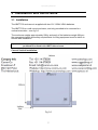
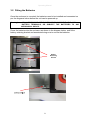
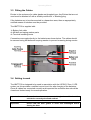
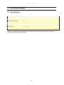
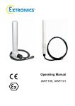
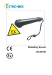
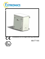
Installation & Operating Manual
iBATT100
Operating Manual
This page is intentionally left blank.
Document Number 331461 (See Last Page for Revision Details)
©2006 Extronics Limited. This document is Copyright Extronics limited.
Extronics reserve the right to change this manual and its contents without notice, the latest
version applies.
2
Operating Manual
Contents
1
2
3
4
5
6
7
Introduction.......................................................................................................... 4
Safety Information and Notes .............................................................................. 5
2.1
Storage of this Manual ................................................................................. 5
2.2
List of Notes ................................................................................................. 5
Installation and Set-to-work ................................................................................. 7
3.1
Installation .................................................................................................... 7
3.2
Fitting the Batteries ...................................................................................... 8
3.3
Fitting the Cables ......................................................................................... 9
3.4
Setting to work.............................................................................................. 9
Intended Purpose Usage................................................................................... 10
4.1
Transportation and Storage........................................................................ 10
4.2
Authorized Persons .................................................................................... 10
4.3
Cleaning and Maintenance......................................................................... 10
4.4
Safety Precautions ..................................................................................... 10
4.5
Cleaning and Maintenance Intervals .......................................................... 10
4.6
Aggressive substances and environments ................................................. 11
4.7
Exposure to external stresses .................................................................... 11
4.8
Lead Acid Batteries .................................................................................... 11
Technical Data .................................................................................................. 12
5.1
Specification ............................................................................................... 12
Certification ....................................................................................................... 13
6.1
Certification Label....................................................................................... 13
6.2
ATEX Certificate......................................................................................... 14
6.3
IECEx Certificate ........................................................................................ 16
6.4
EC Declaration of Conformity ..................................................................... 19
Manual Revision ................................................................................................ 20
3
Operating Manual
1 Introduction
The iBATT100 is an ATEX and IECEx approved wall mount stainless steel
battery enclosure for use in Zone1 and Zone 2 hazardous areas. It is designed
to be used in conjunction with the iUPS101 UPS system to provide an
uninterruptible power supply. The iBATT100 can also be used independently
providing the special conditions for safe use are applied as detailed on the ATEX
/ IECEx certificate.
When used in conjunction with the Ex ‘e’ certified charge protection circuit
contained within the iUPS101 system, users are permitted to charge the two 12V
135Ah valve regulated lead acid batteries in a hazardous area. These batteries
are maintenance free, and thanks to the temperature compensation circuitry
within the iUPS101, they are charged within the manufacturers specified
parameters regardless of environmental conditions.
4
Operating Manual
2 Safety Information and Notes
2.1 Storage of this Manual
Keep this user manual safe and in the vicinity of the device. All persons who have to work on
or with the device should be advised on where the manual is stored.
2.2 List of Notes
The notes supplied in this chapter provide information on the following.
• Danger / Warning.
o Possible hazard to life or health.
• Caution
o Possible damage to property.
• Important
o Possible damage to enclosure, device or associated equipment.
• Information
o
Notes on the optimum use of the device
Warning
Installation to be by skilled electricians and instructed personnel in
accordance with national legislation, including the relevant standards
and, where applicable, in accordance with IEC 79.17 on electrical
apparatus for explosive atmospheres.
Warning!
The iBATT100 must only be operated in Zone 1 and Zone 2 hazardous
area. Refer to the ATEX certificate for further information.
Warning!
If charging takes place in a hazardous area the charging circuits must
meet the requirements of EN60079-0 and EN60079-7.
Warning!
Any load connected to the iBATT100 must include a 160A Fuse in the
supply line. If the fuse is located in a hazardous area it must be suitably
certified.
Warning!
If the batteries are to be disconnected in a hazardous area, then an
appropriately certified means of isolation must be provided.
Important
The batteries must not be subjected to mechanical shock.
Important
The technical data indicated on the iBATT100 ATEX rating plate, in this
manual and the ATEX certificate must be observed at all times.
5
Operating Manual
Important
The ATEX rating label must be fitted at all times, if damaged it must be
replaced immediately or the iBATT100 must be removed from service
and the hazardous area.
Important
Changes in the design and modifications to the equipment are not
permitted.
Important
The iBATT100 shall be operated as intended and only in an undamaged
condition.
Important
Only suitably rated loads may be connected to the iBATT100.
Caution
This assembly may weigh up to 110Kg, therefore ensure the assembly is
mounted using suitable fixtures.
Caution
Never operate the iBATT100 unit outside its rated voltage, current &
power as indicated in the specification or the safety of the unit may be
impaired.
Caution
Never exceed the maximum loading of the iBATT100 as stated in the
specifications. Adequate protection such as a fuse / breaker must be
fitted to connecting equipment to prevent exceeding maximum load.
Important
For the installation, maintenance and cleaning of the units, it is
absolutely necessary to observe the applicable regulations and
provisions concerned with explosion protection (EN60079-0:2009, EN
60079-14:2008) as well as the Accident Prevention Regulations.
Important
The iBATT100 must not be stored or operated outside of its rated
temperature range as stated on the ATEX certificate.
6
Operating Manual
3 Installation and Set-to-work
3.1 Installation
The iBATT100 enclosure is supplied with two 12V 135Ah VRLA batteries.
The iBATT100 is a wall mount enclosure, and only permitted to be mounted in a
vertical orientation – see fig 3.0.
The enclosure weighs approximately 20Kg, and each of the batteries weigh 46Kg so
the appropriate health and safety requirements for lifting equipment must be taken to
ensure safe installation.
Important!
If replacing the batteries, only FEAM 12FLB500 12V 135Ah Batteries are
permitted to be fitted in the iBATT100 enclosure.
Correct Vertical Installation:
Fig 3.0
7
Operating Manual
3.2 Fitting the Batteries
Once the enclosure is mounted, the batteries need to be installed and connected as
per the diagrams below before the unit can be powered up.
Warning!
AT ALL TIMES TAKE GREAT CARE NOT TO SHORT THE LEAD ACID
BATTERY TERMINALS, OR SUBJECT THE BATTERIES TO ANY
MECHANICAL SHOCK.
Place the batteries into the enclosure as shown in the diagram below, and fit the
battery retaining bracket and associated wing-nuts to secure the batteries:
8
Operating Manual
3.3 Fitting the Cables
Entries to the enclosure for cable glands are threaded type. Any Entries that are not
used must be blanked off with a suitably certified Ex ‘e’ blanking plug.
If the batteries are to be disconnected in a hazardous area, then an appropriately
certified means of isolation must be provided.
The iBATT100 is supplied with:
1x Battery link cable
4x M8 bolt and spring washer parts
4x Terminal insulating boots
Connections are made directly to the batteries as shown below. The cables should
be secured using M8 bolts and a spring washer to prevent loosening during service.
3.4 Setting to work
The iBATT100 is designed to be used in association with the iUPS101 Zone 1 UPS
system, as this provides a certified control circuit for safe charging of the batteries.
Once all cables are connected correctly and inspected the enclosure door should be
closed and locked ready for normal operation.
Important!
Ensure the door is secure, correct cable glands are fitted and the
unit device correctly wired and earthed.
Important!
Ensure that the door gasket is clean and undamaged before
closing the door.
9
Operating Manual
4 Intended Purpose Usage
Important
Before setting the units to work, read the technical documentation
carefully.
Important
The latest version of the technical documentation or the corresponding
technical supplements is valid in each case.
The iBATT100 is built using modern components and is extremely reliable in
operation; however it must only be used for its intended purpose. Please note that
the intended purpose also includes compliance with the instructions issued by the
manufacturer for installation, setting up and service.
Any other use is regarded as conflicting with the intended purpose. The manufacturer
is not liable for any subsequent damage resulting from such inadmissible use. The
user bears the sole risk in such cases.
4.1 Transportation and Storage
All iBATT100 devices must be so transported and stored that they are not subjected
to any excessive mechanical stresses.
4.2 Authorized Persons
Only persons trained for the purpose are authorized to handle the iBATT100; they
must be familiar with the unit and must be aware of the regulation and provisions
required for explosion protection as well as the relevant accident prevention
regulations.
4.3 Cleaning and Maintenance
The iBATT100 has two ventilation filters fitted to prevent the ingress of dust and
water. These filters should be inspected periodically, and replaced / cleaned as
necessary.
4.4 Safety Precautions
Important
For the installation, maintenance and cleaning of the units, it is
absolutely necessary to observe the applicable regulations and
provisions concerned with explosion protection (EN 50014, EN 6007914:2003) as well as the Accident Prevention Regulations.
4.5 Cleaning and Maintenance Intervals
The cleaning intervals depend on the environment where the system is installed.
10
Operating Manual
4.6 Aggressive substances and environments
The iBATT100 is not designed to come into contact with aggressive substances or
environments, please be aware that additional protection may be required.
4.7 Exposure to external stresses
The iBATT100 is not designed to be subjected to excessive stresses e.g. vibration,
heat, impact. Additional protection is required to protect against these external
stresses.
The iBATT100 will require additional protection if it is installed in a location where it
may be subjected to damage.
4.8 Lead Acid Batteries
The rechargeable valve regulated lead acid batteries contained within the iBATT100
have an operational life of up to 10 years dependant on charge/discharge cycles and
ambient temperature conditions. These batteries may be changed in the field by the
customer under safe area conditions. Please note it is essential that this work is
carried out by a competent person and care must be taken not to short the +/terminals of the batteries.
11
Operating Manual
5 Technical Data
5.1 Specification
Input Voltage
24Vdc (18-36Vdc)
Output Voltage
24Vdc (18-36Vdc)
Maximum Discharge Current
160A
Maximum Charge Current
40A
Enclosure Material
316 Stainless Steel
Weight
Approximately 110 Kg
Enclosure Ingress Protection
IP45*
Environmental
-20ºC to +55ºC
Certification
Ex II 2G Ex e IIC T6 Gb
*ATEX ingress protection is IP23 as the filter material may degrade over long periods of time if not
inspected. Providing regular inspection and replacement of this filter material is carried out, then the
enclosure protection will remain as IP45
12
Operating Manual
6 Certification
6.1 Certification Label
13
Operating Manual
6.2 ATEX Certificate
14
Operating Manual
15
Operating Manual
6.3 IECEx Certificate
16
Operating Manual
17
Operating Manual
18
Operating Manual
6.4 EC Declaration of Conformity
19
Operating Manual
7 Manual Revision
Revision
REL01
01
02
Description
First Issue
Approved Document
Changed entries to threaded and deleted batteries supplied in
enclosure
20
Date
30/09/2011
18/10/2011
15/02/2012
By
A. Peek
B. Seaby