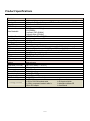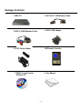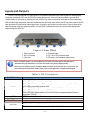
1
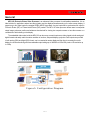
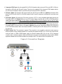
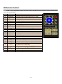
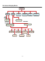
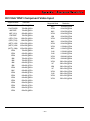
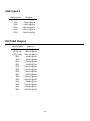
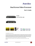
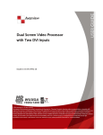
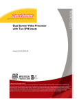
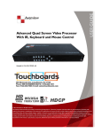
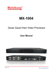
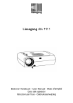
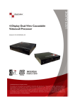
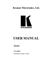
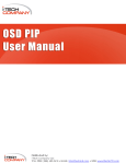
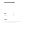
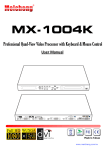
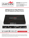
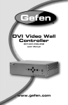
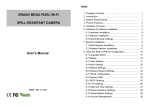
PIP Video Processor User Manual Design IN USA [Model Number: MPV-100] Safety and Notice The MPV-100 Picture-In-Picture Video Processor has been tested for conformity to safety regulations and requirements, and has been certified for international use. However, like all electronic equipments, the MPV-100 should be used with care. Please read and follow the safety instructions to protect yourself from possible injury and to minimize the risk of damage to the unit. Follow all instructions and warnings marked on this unit. Do not attempt to service this unit yourself, except where explained in this manual. Provide proper ventilation and air circulation and do not use near water. Keep objects that might damage the device and assure that the placement of this unit is on a stable surface. Use only the power adapter and power cords and connection cables designed for this unit. Do not use liquid or aerosol cleaners to clean this unit. Always unplug the power to the device before cleaning. Table of Contents Chapter 1 Introduction 1 General 1 Features 2 Specifications Package Contents 3 4 Inputs and Outputs 5 Chapter 2 Hardware Installation 6 Safety Precautions Installation Procedures 6 6 Operations 8 IR Remote Control On Screen Display Menu 9 10 Chapter 3 Software Operation 12 System Requirement and Precautions Instruction of Software Connection 12 12 Instruction of Software Operation 14 Chapter 4 Troubleshooting 18 Appendix Supported Resolution 23 Introduction General MPV-100 Picture-In-Picture Video Processor is an advanced video processor for multimedia presentations. It is an ideal solution for applications where two video signals must be displayed simultaneously on the same screen display. It supports up to four video inputs for computer RGB or HD/SD type videos. Any two inputs will be synchronized for output in Picture-In-Picture (PIP) or Picture-Aside-Picture (PAP) modes. The MPV-100 video processor allows users to manipulate output images, wherever position and whatever sizes desired for viewing two computer screens or two video screens or a combination of both showing on the display. The embedded video scaler inside the MPV-100 can also cross converts input source video signals to both analog and digital formats and easily match the native resolution of monitors, flat panel displays, projectors. Dual outputs are provided in both analog (VGA) and digital (DVI) format, one is connected to remote display and the other is connected to on-site display for real time monitoring with user-selectable output settings up to WUXGA at 1920x1200 pixels or HD resolution up to 1080p. Figure 1: Configuration Diagram ~1~ Product Features Multi-Function digital video scaler and PIP video generator. Professional multi-view video mixer with simultaneous digital DVI-D and analog VGA outputs. Dual HD video scaling engines built in for easy cross conversion between different video formats. Converts DVI, VGA, HD component YPbPr video and SD composite video to both DVI-D and VGA type for output up to 1920x1200 pixels or 1080p. High-performance analog-to-digital and digital-to-analog video format converter designed to output in a wide range of digital resolution. Any SD/HD input can up-scaled or down-scaled in a selectable HD or computer RGB video resolution and match the native resolution/format of users’ displays for highest picture quality. Supports computer DVI-D and VGA type RGB inputs from 640x480 to 1920x1200 pixels. Supports HD Component YPbPr and Composite video inputs from 480i to 1080i/1080p. Full control of Picture-In-Picture, PAP and full screen modes via IR remote control or a RS232 link with a PC. Adjustable PIP/PAP video window sizes and position through the RS232 software. Supports independent image freeze controls on both main channel and sub video channel, enabling video frames to be paused or captured for extended period of time for detailed presentation. Supports easy SWAP function for interchanging video channels. The main video channel and the PIP sub window can be swapped effortlessly and instantly showing on the screen display through the “SWAP” push button on the remote controller. Selectable video windows sizing, positioning, horizontal/vertical flip, zoom/pan and blend functions for output video. Easy on-screen OSD setup menu for user friendly configuration and operation. Featured with multiple-level control of adaptive deinterlacing and noise reduction functions for output video. Image parameters adjustable (brightness, contrast, color temperature, etc) and layouts are automatically saved in flash memory and can be recalled for later use. All image adjustment parameters and layouts can be saved in files and can be loaded for later use. Full-featured IR remote controller included. Supports advanced control and distance operation through the RS-232 console port. RS232 control software supports Win98/2000/Vista/Me and Win7. Automatically power-saving mode. ~2~ Product Specifications Technical Role of usage Video Inputs Video Output HDCP Compliance Video Bandwidth Max Video Resolution Audio Support Distance Control Split Screen Mode Input TMDS signal ESD protection PCB stack-up IR remote control DVI connector VGA connector RS-232 connector RCA connector Mechanical Housing Dimensions (L x W x H) Fixedness Power supply Power consumption Operation temperature Storage temperature Relative humidity Package Contents Multiplexer / video processor VGA In x 2 + DVI In x 1 + Component YPbPr x 1 + Composite In x 1 + 1x RS-232 DVI-D Out x 1 + VGA Out x 1 No DVI-D [Single-link 4.95Gbps] VGA [165MHz] Component YPbPr [30MHz] Composite Video [13.5MHz] 1080P/60Hz Or 1920x1200@75Hz No RS-232 and IR remote control PIP / PAP 1.2 Volts [peak-to-peak] Human body model — ±15kV [air-gap discharge] & ±8kV [contact discharge] 6-layer board [impedance control — differential 100; single 50] Electro-optical characteristics: = 25 / Carrier frequency: 38kHz DVI-I [29-pin female, digital only] HD-15 [15-pin D-sub female] DE-9 [9-pin D-sub female] 75 Metal enclosure 180 x 103 x 23mm [7.1”x4”x0.9”] Wall-mounting case 5V 4A DC 10 Watts [max] 0~40C [32~104F] -20~60C [-4~140F] 20~90% RH [no condensation] 1x MPV-100 1x DVI to DVI/VGA breakout cable 1x VGA to component breakout cable 1x VGA to DVI adapter ~3~ 1x 5V power adapter 1x IR remote controller 1x Installation software CD 1x User Manual Package Contents 1. MPV-100 2. DVI To DVI / VGA Breakout Cable 4. DVI To VGA Adapter 3.VGA To YPbPr Breakout Cable 5. 5V DC Power Adapter 6.IR Remote Controller 7. RS232 Console Control Software CD 8. User Manual ~4~ Inputs and Outputs The MPV-100 supports total of 4 video inputs for all computer RGB and HD type video signals from desktop/laptop computers, workstation, DVR, and all NTSC/PAL analog video sources. Users can use this product to generate dual channel display on one screen by selecting any two out of the four video input sources connected for visual presentation. With one video input reserved for main video window and the other video input used for the PIP sub video channel, this PIP video generator will combine both video inputs in sync for output in split screen or overlay screen. Figure 2 shows all the video connectors of the back panel from a MPV-100 and Table 1 illustrates how users can connect video devices and display through the MPV-100. 4 Figure 2: Rear Panel 1. Power connector 2. DVI / VGA output 3. VGA input 4. Composite input 5. DVI / VGA / HD Component input 6. DIP switch* (for firmware & system reset) *Reset to default values: Turn on the MPV-100 unit then turn both dials on the DIP switch simultaneously up and down to reset the unit back to the factory default mode. *These IO ports support various computer RGB resolution from 640x480 up to 1920x1200, for more detail of the supported modes, please refer to the Appendix – Supported Resolution. Table 1: I/O Connectors Input Connector DVI-IN VGA Composite Output Connector DVI-I OUT Video Source Option [1]: DVI input via the DVI cable Option [2]: VGA input via using a DVI-to-VGA adapter Option [3]: HD Component (YPbPr) input via the combination of using a DVI-to-VGA adapter and a VGA-to-component breakout cable Option [4]: DVI input + VGA input via using a DVI-to-DVI/VGA breakout cable Option [5]: DVI input + Component (YPbPr) input via the combination of using a DVI-to-DVI/VGA breakout cable for DVI IN and a VGA-to-component breakout cable for component YPbPr IN. 2nd VGA input via using a VGA cable Analog composite video input via using a RCA A/V cable Display [1] DVI display [2] VGA display — with a DVI-to-VGA adapter [3] 1x DVI display + 1x VGA display — with a DVI to DVI/VGA breakout cable ~5~ Hardware Installation Safety Precautions I. To prevent fire or shock hazards, do not expose this device to rain or moisture. II. When connecting other products such as DVD players, and personal computers, you should turn off the power of this product for protection against electric shocks. III. The product should be placed more than one foot away from heat sources such as radiators, heat registers, stoves, and other products (including amplifiers) that produce heat. In addition, do not cover any material or devices on the top of the device. IV. Do not use immediately after moving from a low temperature to high temperature, as this causes condensation, V. Do not place this product on an unstable cart, stand, or table. The product may fall, causing serious injury to a child or adult and serious damage to the product. VI. Unplug this product from the wall outlet before cleaning. Do not use liquid cleaners or aerosol cleaners. Use a damp cloth for cleaning. VII. Do not allow the same still picture to be projected for a long time or an abnormally bright video picture to be projected. The video image could be burned in to the display device. Installation Procedures Unpacking Remove the MPV-100 from the shipping container and examine it for any signs of shipping damage or missing items (check with package contents above). All shipping items should be saved if the product is to be moved or returned for service. Shipping unit back to dealers for service not in the original box may result in voiding warranty or additional cost. Placement The unit uses convection to cool. A fan is not needed, so do not block the sides of this device or stack another device on the top or bottom of the MPV-100. Connections 1. Switch off the MPV-100 and all video source devices that you want to connect with MPV-100. 2. CV Input: Connect your composite video device to composite RCA input of the MPV-100. 3. VGA Input: [Option 1] Connect your VGA device such as laptop directly into the VGA input of MPV-100. The 15-pin D-sub input on the MPV-100 is the 2nd VGA input. [Option 2] Connect your VGA device to the VGA end of the DVI to DVI/VGA breakout cable. The VGA input via using the DVI to DVI/VGA breakout is considered the 1st VGA input. Note: you can always connect 2 video sources mixed with either DVI, VGA or Component YPbPr type together into the DVI input of MPV-100 with the help of combining the DVI-to-DVI/VGA breakout cable for DVI/VGA IN and a VGA-to-component breakout cable for component YPbPr IN. ~6~ 4. Component YPbPr Input: Use the supplied DVI to DVI/VGA breakout cable to plug into DVI input of MPV-100 first so there will be a DVI end and VGA end for inputs. Then plug in the supplied VGA to component YPbPr adapter cable to the VGA end of the breakout cable for connection with your component YPbPr video device. 5. DVI Input: [Option 1] Connect the DVI source directly into the DVI input of MPV-100. [Option 2] Connect the DVI device to the DVI end of the DVI to DVI/VGA breakout cable if used for necessity of hookups with more video input devices. 6. DVI Output: [Option 1] Connect your DVI monitor, projector, LCD TV or other compatible digital display directly into DVI output of MPV-100. [Option 2] Connect your DVI monitor display to the DVI end of a DVI to DVI/VGA breakout cable if dual outputs needed. Note: You can always use additional DVI to DVI/VGA breakout cable on the DVI output port of MPV-100 for connecting with one DVI display and one VGA display at the same time. 7. VGA Output: [Option 1] Connect your VGA monitor, projector, LCD TV or other compatible digital display directly into DVI output of MPV-100 using a DVI to VGA adapter. [Option 2] Connect your VGA monitor display to the VGA end of a DVI to DVI/VGA breakout cable if dual outputs needed for connecting with one DVI display and one VGA display at the same time. 8. RS232 Console Port: This connection is optional. This connection is only needed for advanced console control or distance operation using a Windows-based PC for controlling the operation the MPV-100. You can use a 9-pin RS-232 serial port cable or a USB to RS232 adapter cable for connection between MPV-100 unit and a PC for advanced console control or distance operation. After the RS232 serial connection is well established, please install the RS232 application software from the cd disc included in the package to the PC for manual control and operation use. Figure 3: Connection Diagram ~7~ Operations 1. Use the supplied power adapter to connect your MPV-100 unit and the AC power outlet on the wall. 2. Complete all the cable connections as instructed for the needed application setup. Refer to the instructions in the above paragraph. 3. Power on all source devices connected first then switch on your MPV-100 video processor and lastly power on your video displays. 4. Press “menu” button from the IR remote controller to display OSD menu. 5. Press the down arrow key from the remote controller to drop down the sub-menu and select the video source input for the Main Channel display. 6. Once finishing selecting the video source for the main video channel, press the “EXIT” key from the remote controller to exit the sub-menu, and then move right to the next item of OSD menu, which allows you to select the video input source for the second channel display (Sub Channel). For detailed IR remote control operation, please refer to next paragraph for the On Screen Display menu and IR operating instruction. ~8~ IR Remote Control The MPV-100 is shipped with a compact IR remote controller that allows for direct access to most commands used to control the video processor. (1) (2) (3) (4) (5) (6) (7) (8) (9) (10) (11) (12) (13) (14) (15) (16) (17) Power PIP Border Up Button Source Reset Right Button Menu Left Button Logo Exit Down Button Enter Blank Color Auto V Flip H Flip (18) SWAP (19) (20) (21) PIP Sub Pause Main Pause Power on/off the device Display the border of small image (under PIP mode) Move to the upper titles Press to select a source for main channel Factory Reset Move to the right titles Display OSD menu Move to the left titles Display a logo Move back to previous option or exit OSD menu Move to the lower titles Press to drop down sub-menus or confirm the selection Blank out the screen Automatically configure the main channel color Automatically configure the main channel position Flip the screen vertically Flip the screen horizontally Swap between main channel and sub-channel (only works in PIP or PAP mode) Change modes among full screen, PIP, PAP Freeze the images on the PIP channel Freeze the images on main channel ~9~ (4) (8) (12) (3) (7) (11) (2) (6) (10) (1) (5) (9) (13) (17) (16) (15) (14) (21) (20) (19) (18) On Screen Display Menu Menu Main Sub Down Button OSD Control Language Selection Factor y Reset Down Button Main Sourc e Sub Source Enter Button Enter Button Sub Control Main Control Displa y Positio n Imag e Borde r PIP Contro l Color ~ 10 ~ Logo Resolutio n Selection Main Source: Select an input source for the main channel (VGA / YPbPr, DVI, Composite, VGA) Main Control: Display Brightness (Slider) Contrast (Slider) Hue (Slider) Saturation (Slider) Flesh-tone (Button: Off, Weak, Soft, Strong) Image Scaling (1:1, Fill, Aspect, Panor) Adaptive Deinterlacing (Button: Off, Level 1, Level 2, Level 3) Noise Reduction (Button: Off, Low, Med, High) Angle Filtering (Button: Off, On) Film Mode Detect (Button: Off, On) Sharpness (Slider) Position Zoom(Button: In, Out) Zoom Horizontal Pan (Button: Left, Right) Zoom Vertical Pan (Button: Down, Up) Vertical (Slider) Horizontal (Slider) Color RGB (Button: Off, On Cl.BA) Gamma Correction (Button: Off, 2.2, 2.4) Color Temperature (Button: User, 6500K, 9300K) Red (Slider) Green (Slider) Blue (Slider) PIP Control PIP Mode (Off, Single, PAP) PIP Size (Small, Medium, Large) Vertical (Slider) Horizontal (Slider) Blend (Slider) Logo (Off, On) Border (Off, On) Red (Slider) Green (Slider) Blue (Slider) Width (Slider) Sub Source: Select an input source for sub-channel (VGA/component, DVI, composite, VGA) Sub Control: The same as Main Control OSD Control: Vertical (Slider) Time out (Slider) Horizontal (Slider) OSD Zoom (On, Off) Blend (Slider) Language Selection: English and Traditional Chinese Factory Reset: Reset the device back to default values Resolution Selection: Press Down Button to select an output resolution and then press enter to confirm that selection. 800×600 @60Hz 1280×768 @60Hz 1440×900 @60Hz 1920×1080 @50Hz 1024×768 @60Hz 1280×1024 @50Hz 1400×1050 @50Hz 1920×1080 @60Hz 1152×864 @75Hz 1280×1024 @60Hz 1400×1050 @60Hz 1920×1200 @50Hz 1280×720 @50Hz 1366×768 @60Hz 1600×1200 @60Hz 1920×1200 @60Hz 1280×720 @60Hz ~ 11 ~ Operation Software System Requirement and Precautions 1. The MPV-100 provides a software control program which runs under Microsoft Windows 98/2000/XP/Vista/Win 7 through the RS-232 terminal control. 2. Before you click on the icon of the software, make sure you have secured the connection between your computer COM port and the MPV-100 and switched on the MPV-100 with green LED light. 3. MPV-100 can be commanded by using the remote controller and RS232 software control. To make sure all information shown in the software is synchronized with those in the device, please click “Connect” to acquire the latest data from the MPV-100 after you press any key on the remote control. Instruction of Software Connection 1. Power up the MPV-100 and you can see both red and green LEDs on the front panel blink. Make sure the serial port (RS-232) connection secure. 2. The first step after running the software is to automatically detect if the device responses correctly through RS-232 port. The process takes 15-20 seconds. If the response is not accurate, a warning window will show up as the figure below. The possible reasons causing this failure could be: The MPV-100 is not supplied with power or the MPV-100 enters deep sleep state. Please check the current status, and reboot the MPV-100 The serial connection through RS-232 is not well established or some other software has taken the available serial ports. Please make sure the RS-232 cable is well connected and the available serial port is free to be used by the MPV-100. ~ 12 ~ 3. If the serial connection is well established, you can see similar work window as below. 4. While you move the mouse’s cursor near the borders, in either red or blue, the icon of the cursor will change as the figure below. ~ 13 ~ Instruction of Software Operation File a. Connect: This will synchronize the status of the MPV-100 with that of the software, especially after IR commands sent. b. Save Setting: This will save current user preferred settings such as the positions and sizes of the videos, the width or color of border etc. into your favorite setting files. c. Load Setting: The function will load the favorite settings from the previously saved file. d. IR Control: This will enable or disable the IR remote control. e. Auto Sleep: This decides if the MPV-100 enters the deep sleep mode if the video signal cannot be detected in the main channel. f. Factory Reset: This will restore all the system values back to the factory default. g. Exit: Quit the software. Background a. Resolution: Change the output resolution. b. Layout: The preset layout for main & sub channels. ~ 14 ~ c. HFlip: Horizontally flip the output video. d. VFlip: Vertically flip the output video. e. SWAP: Swap the main and sub channel. f. Color: The background color selection. g. Custom Size 1-3: Save or read main/sub channel size, position, visible and Layer. ~ 15 ~ Main a. Input Source: Select a video/graphic input of the main channel. b. Visible: Display the main channel or not. c. Border: Display the main channel’s border. d. Label: Display the main channel’s label. Users can define the content of the label. e. Layer: This will make the main channel overlays the sub channel. f. Pause: Freeze the display of the main channel. g. Full Screen: Display the main channel full screen. h. Color Balance: Automatically do the color balance while the main channel’s input is from VGA/component. i. Auto Config.: Automatically do the auto adjustment while the main channel’s input is from VGA/component. Sub a. Input Source: Select a video/graphic input of the sub-channel. b. Visible: Display the sub-channel or not. c. Border: Display the sub-channel’s border. d. Label: Display the sub-channel’s label. Users can define the content of the label. e. Layer: This will make the sub-channel overlays the main channel. f. Pause: Freeze the display of the sub channel. ~ 16 ~ Control- Setting Dialog Border Select main or sub channel for further setting. PAP mode only 1. Border Color: Setup border’s color by clicking on “Color setting”. 2. Border Width: Input border’s width. 3. Border Type: The placement of border has two types: Option Inside means the added border is fully inside the video. Option Outside means the added border is completely outside the video and this added border can overlay the other video input. 4. Text Color: Select the color of the label by clicking on “Color Setting” button. 5. Text Auto: While selecting “Text Auto”, the label on the screen for each channel will display its corresponding input channel type. While unselecting “Text Auto”, users can input the desired string to be displayed. Only 15 English characters can be displayed at most. ~ 17 ~ 6. Duty Cycle: The duty cycle of blinking of OSD borders and labels. 7. Frequency: How fast the blink. Image 1. Choose the scaling type for the main channel at full screen display. 2. While Blend is selected, users can use the slider to control the degree of blending. There is a short period of slight blinking while the MPV-100 processes the blending of the two input videos. ~ 18 ~ Color 1. Select the main or sub channels. 2. Reset: Restore all the setting on this page back to their default values. Zoom A. Select the main or sub channel. B. Default: Restore the selected channel without zoom effect. A B ~ 19 ~ A. This scroll bar controls the ratio of Zoom. B. The workplace for controlling the displayed area after zooming the selected video. A B Pattern 1. While “Pattern Model” is chosen, the output will display the selected pattern. While unselecting this item, the output display works normally. 2. The orange border indicates which pattern is currently selected. Users can choose one of the provided patterns by moving cursor and clicking at the desired one. 3. Define the pattern’s color by clicking at the rectangle inside the ellipse, and then use the sliders for choosing R, G, B depths. ~ 20 ~ HS / VS Delay 1. Select the main or sub channel. 2. Adjust Main /Sub Channel size and position 3. The fine movement of the selected channel. EDID Code 1. Save: Save the read back EDID Content in PC. 2. Setting: Automatically setup the output resolution according to the content of EDID. This setting is according to the content of EDID, and the optimum resolution for the monitor might be different because of the limited information of the acquired EDID info. ~ 21 ~ Troubleshooting Problem No power Recommendations Check if you are using 5V DC adapter and it is firmly plugged into the MPV-100 If you are recovering from power outage, accidentally unplug the adapter or other power surge conditions, leave the device off for a while and then power it on again. No/ Erratic video Make sure all cables are in good working condition and properly connected to the MPV-100 and displays. Configure the output video resolution so that it doesn’t excess the native resolution of the display. ( in this case, the message of “out of range” is usually showed on your screen) Make sure a video source is selected to the main channel. (press “Menu” and check if the first item has a video source selected or press “Source” to select a video source for the main channel) Poor quality We suggest that don’t use T-connectors to split your video source into to images displayed on two different screens. That will lower output video quality. Use a distribution amplifier instead of T-connectors. Make sure the video source is not compressed and maintains the highest native resolution. Image position shifted Press “Auto” key on the remote control. Auto color configuration only works at VGA and component inputs. Wrong color Press “Color” key for auto color configuration. Auto color configuration only works at VGA and component inputs. ~ 22 ~ Appendix – Supported Resolution DVI VGA YPbPr Component Video Input Supported Mode Resolution NTSC/480I/525I 720x240 @60Hz PAL/576I/625I 480P/525P 720x288 @50Hz 720x483 @60Hz 480P (16:9) 960x483 @60Hz 576P/625P 720x756 @50Hz (HDTV) 720p 1280x720 @50Hz (HDTV) 720p (HDTV) 1080i 1280x720 @60Hz 1920x1080 @50Hz (HDTV) 1080i 1920x1080 @60Hz (HDTV) 1080p VESA 1920x1080 @30Hz 720x400 @85Hz VESA 640x350 @85Hz VESA IBM 640x400 @85Hz 720x400 @70Hz IBM IBM 720x350 @70Hz 640x350 @70Hz IBM VESA 640x400 @70Hz 640x480 @60Hz MAC 640x480 @67Hz VESA VESA 640x480 @72Hz 640x480 @75Hz VESA VESA 640x480 @85Hz 800x600 @56Hz VESA VESA VESA VESA 800x600 @60Hz 800x600 @72Hz 800x600 @75Hz 800x600 @85Hz ~ 23 ~ Supported Mode Resolution MAC VESA 832x624 @75Hz 1024x768 @60Hz MAC 1024x768 @60Hz VESA 1024x768 @70Hz IBM VESA 1024x768 @72Hz 1024x768 @75Hz MAC 1024x768 @75Hz VESA 1024x768 @85Hz VESA MAC 1152x864 @75Hz 1152x870 @75Hz SUN SUN 1152x900 @66Hz 1152x900 @76Hz VESA 1280x960 @60Hz VESA VESA 1280x960 @85Hz 1280x1024 @60Hz HP IBM 1280x1024 @60Hz 1280x1024 @67Hz HP VESA 1280x1024 @72Hz 1280x1024 @75Hz SUN VESA 1280x1024 @76Hz 1600x1200 @60Hz VESA 1920x1200 @60Hz VGA Input 2 Supported Mode Resolution VESA VESA 640x480 @60Hz 800x600 @60Hz VESA 1024x768 @60Hz VESA 1280x1024 @60Hz VESA 1600x1200 @60Hz VESA 1920x1200 @60Hz DVI/VGA Output Supported Mode Resolution (HDTV) 720p 1280x720 @50Hz (HDTV) 720p (HDTV) 1080p 1280x720 @60Hz 1920x1080 @60Hz VESA VESA 640x480 @60Hz 800x600 @60Hz VESA VESA 1024x768 @60Hz 1152x864 @75Hz VESA VESA 1280x1024 @60Hz 1280x1024 @50Hz VESA 1280x768 @60Hz VESA VESA 1366x768 @60Hz 1400x1050 @60Hz VESA VESA VESA VESA VESA 1400x1050 @50Hz 1152x864 @75Hz 1600x1200 @60Hz 1920x1200 @50Hz 1920x1200 @60Hz ~ 24 ~