1
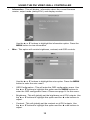
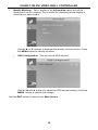
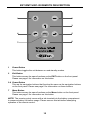
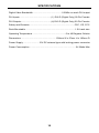
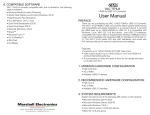
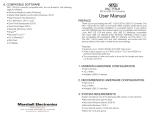
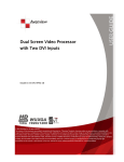
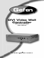
DVI Video Wall
Controller
EXT-DVI-VWC-242
User Manual
www.gefen.com
f
ASKING FOR ASSISTANCE
Technical Support:
Telephone
(818) 772-9100
(800) 545-6900
Fax
(818) 772-9120
Technical Support Hours:
8:00 AM to 5:00 PM PST Monday thru Friday Pacific Time
Write To:
Gefen LLC
c/o Customer Service
20600 Nordhoff St
Chatsworth, CA 91311
www.gefen.com
[email protected]
Notice
Gefen LLC reserves the right to make changes in the hardware, packaging and
any accompanying documentation without prior written notice.
DVI Video Wall Controller is a trademark of Gefen LLC
All trademarks are the property of their respective owners.
© 2010 Gefen LLC, All Rights Reserved
Rev A1
CONTENTS
1
Introduction
2
Operation Notes
3
Features
4
Panel Layout
5
Panel Descriptions
6
Connecting And Operating The DVI Video Wall Controller
7
Using The DVI Video Wall Controller
15 EXT-RMT-VWC-IR Remote Description
16 Specifications
17 Warranty
INTRODUCTION
Congratulations on your purchase of the DVI Video Wall Controller. Your
complete satisfaction is very important to us.
Gefen
Gefen delivers innovative, progressive computer and electronics add-on solutions
that harness integration, extension, distribution and conversion technologies.
Gefen’s reliable, plug-and-play products supplement cross-platform computer
systems, professional audio/video environments and HDTV systems of all sizes
with hard-working solutions that are easy to implement and simple to operate.
The Gefen DVI Video Wall Controller
Create a 2x2 video wall for a digital signage application. Play back video at
trade shows, control center, indoor lobby or other venues. The Gefen Video Wall
Controller takes one DVI input to display on four displays at up to 1920x1200p60.
Also, features include video adjustment to many displays and bezel sizes,
thanks to its border control feature. A built-in on-screen display (OSD) facilitates
operations. An IR remote is included.
The Gefen Video Wall Controller creates a 2x2 video wall by default setting,
with a maximum resolution of 1920x1200p60 supported on each output. Many
video wall configurations are selectable which include full-screen enlargement,
horizontal array, four identical displays, and more. Multiple input and output
resolutions are supported. Each video quadrant is scaled and optimized.
Automated control is supported with RS-232 communications.
How It Works
Connect the Video Wall Controller to a DVI source (which could be a satellite
tuner, a computer/player producing output for digital signage, or just a set-top
box.) Connect up to four DVI-compliant displays to the unit. The input signal
will be split and scaled to a maximum resolution of 1920x1200p60 on each DVI
output. Use the buttons on the front panel or the included remote control to adjust
settings.
Note: HDCP-encoded sources are not supported.
1
OPERATION NOTES
READ THESE NOTES BEFORE INSTALLING OR
OPERATING THE DVI VIDEO WALL CONTROLLER
•
The DVI Video Wall Controller does not support HDCP protected content.
•
This product will only support the RGB colorspace (YCbCr is not supported).
•
Digital DVI-D only is supported on the input and output connectors, i.e.
DVI-D.
•
Please see page 8 for a complete listing of the supported input and output
resolutions.
•
This unit generates a significant amount of heat and proper ventilation is
necessary to ensure maximum product longevity.
2
FEATURES
Features
•
Split and scale a single DVI-D source to up to four DVI displays at once
•
Easy-to-navigate OSD menu system
•
Adjustable border control feature
•
Input resolutions up to 1920x1200p60
•
Output resolutions up to 1920x1200p60
•
Fanless design for whisper-quiet operation
•
Pair of rack ears included
•
IR remote control included
•
Field upgradable using RS-232 serial communication
•
Locking external power supply connector eliminates power interruptions if
power cable is snagged or pulled
Package Includes
(1) DVI Video Wall Controller
(1) 6-foot DVI Cable (M-M)
(1) EXT-RMT-VWC-IR remote control
(1) 12V DC External Power Supply
(1) 6-ft DB9 Serial Cable (M-F)
(1) User’s Manual
3
PANEL LAYOUT
Front Panel
1
2
3
4
5
Back Panel
6
7
8
4
9
PANEL DESCRIPTIONS
1
Power LED Indicator
This LED will be active when the DVI Video Wall Controller is receiving power.
This is a dual colored LED. This LED will be GREEN when a valid/active input
signal is detected. This LED will be ORANGE when there is no active or valid
input signal detected.
2
Menu Button
This button will engage the on-screen menu. This button is also used as the OK
button to confirm selections and changes when using the on-screen menu.
3
Navigation Buttons
These buttons (◄▲►▼) are used to navigate the on-screen menu.
4
Exit Button
This button is used to navigate back to the previous screen when using the onscreen menu. When on the top-most level, the on-screen menu will exit.
5
IR (Infrared) Receiver
This receiver will receive commands from the included EXT-RMT-VWC-IR
remote control. Line-of-sight must be preserved for proper operation to occur.
6
RS-232 Serial Communication Port
This port is used to perform firmware updates.
7
DVI Output Ports 1-4 (Digital Only)
These outputs will each support a single DVI compliant display device. The
output ports support digital DVI only (DVI-D).
8
DVI Input Port (Digital Only)
This input will support a single DVI compliant device source device. The input
source will be split, scaled, and output via the DVI output ports. The inputs
accept digital DVI only (DVI-D).
9
12V Locking DC Power Input
This input will receive power from the included locking 12V DC power supply.
When attaching the power cable, screw in the locking connector until it refuses
to move any further (do not overly tighten).
5
CONNECTING AND OPERATING THE DVI VIDEO WALL CONTROLLER
How to Connect the DVI Video Wall Controller
1.
Connect the DVI source to the DVI Video Wall Controller’s DVI input port
using the supplied DVI cable.
NOTE: Please see page 8 for a complete listing of the supported input and
output resolutions.
2.
Connect up to four DVI compliant display devices to the DVI output ports
using user supplied DVI cables.
3.
Connect the included 12V DC power supply to the power input on the rear
panel of the unit and the plug-end into an open wall power socket.
How to Operate the DVI Video Wall Controller
The DVI Wall Controller does not require much setup to begin operation. All
operation of the on-screen menu is done using either the front panel buttons or
the IR remote control.
For operation using the front panel control buttons please see page 7.
Operation using the included remote control mirrors the front panel buttons. There
are corresponding buttons on the remote control that act exactly like the front panel
buttons.
6
USING THE DVI VIDEO WALL CONTROLLER
The front panel buttons provide quick access to the functions on the DVI Video
Wall Controller. Please note that the functions listed in this section can also
be accomplished by using the same buttons found on the included IR remote
control.
NAVIGATION
The following buttons are present on the front panel:
•
Menu Button: This button will initialize the on-screen display. This on-screen
menu will appear on Display 4. This button will also be used to confirm
selections and initiate changes. i.e. This button can also be thought of as an
OK button.
•
Navigation Buttons: These buttons function as directional navigation for the
on-screen GUI.
•
Exit Button: This button will navigate the user to the previous screen. When
on the top-most menu, this button will exit the on-screen menu.
OPERATION
To initialize the on-screen menu, press the MENU button. The Main Screen
screen should appear on Display 4. The menu that is displayed is the top-most
level. To exit the on-screen menu press the EXIT button. The Main Screen will
appear like the image below.
7
USING THE DVI VIDEO WALL CONTROLLER
From the Main Screen the following options are available:
•
Display - Controls the output resolution, screen mode, and masking control
•
System - product and display information. Global contrast and brightness
controls can also be found under this option.
Use the ▲ or ▼ buttons to select the desired option. Press the MENU button to
enter the selected option’s menu.
Display
The Display menu consists of the following items:
•
Output Resolution - This will globally set the DVI output resolution for all
DVI outputs. Please see the table below for a list of all supported input and
output resolutions.
Input Resolutions
720x350
832x624
1152x900
1680x1050
640x400
1024x768
1280x768
1920x1200
720x400
1152x648
1280x960
720x480 i/p
640x480
1152x870
1280x1024
1280x720
800x600
1152x870
1600x1200
1920x1080 i/p
1360x768
1400x1050
1600x1200
1366x768
1280x1024
1680x1050
1920x1200
1920x1080
Output Resolutions
By default, the Output Resolution option should already be highlighted.
Press the ◄ or ► buttons to change the output resolution. Press the MENU
button to confirm the change.
•
Display Mode - This option will set the output configuration of the DVI Video
Wall Controller. Please see the illustrations below for information on the
modes.
8
USING THE DVI VIDEO WALL CONTROLLER
The Illustration on the previous page depicts the display orientation for
the following modes.
•
1x1: The input signal is duplicated on all outputs
•
1x2: The input signal will span horizontally across displays 1&2 and
3&4.
•
2x2: The input signal will be split into 4 quadrants to create a single
image over outputs 1, 2, 3 and 4.
9
USING THE DVI VIDEO WALL CONTROLLER
•
Mode 1: This mode is similar to the 2x2 mode but the entire input signal
will be displayed on output 1.
•
Mode 2: This mode is similar to the 2x2 mode but the entire input signal
will be displayed on output 2.
•
Mode 3: This mode is similar to the 2x2 mode but the entire input signal
will be displayed on output 3.
10
USING THE DVI VIDEO WALL CONTROLLER
•
Mode 4: This mode is similar to the 2x2 mode but the entire input signal
will be displayed on output 4.
Use the ▲ or ▼ buttons to highlight the Display Mode option. Press the
◄ or ► buttons to change the mode. Press the MENU button to confirm
the change.
•
Mask Control - This will set the masking (border compensation) amount that
is used to adjust the display to compensate for monitor bezels. Use the ▲ or
▼ buttons to highlight this option. Press the MENU button to enter this item’s
submenu.
•
Horizontal - This will set the horizontal masking control. Use the ▲ or
▼ buttons to highlight the horizontal option and the ◄ or ► buttons to
adjust.
•
Vertical - This will set the vertical masking control. Use the ▲ or ▼
buttons to highlight the vertical option and the ◄ or ► buttons to adjust.
11
USING THE DVI VIDEO WALL CONTROLLER
•
Mask Control - This will enable/disable the masking feature. Use the ▲
or ▼ buttons to highlight this option and the ◄ or ► buttons to adjust.
Any changes, enabling/disabling or changing masking percentages,
must be confirmed but selecting this option and pressing the Menu
button.
Use the EXIT button to return to the Main Screen.
System
The System menu consists of the following items:
•
Factory Reset - This will reset the unit to its default settings.
Use the ▲ or ▼ buttons to highlight the factory reset option. Press the
MENU button to enter perform a factory reset..
12
USING THE DVI VIDEO WALL CONTROLLER
•
Information - This will display information about the current firmware
version, output mode (always DVI), and display number.
Use the ▲ or ▼ buttons to highlight the information option. Press the
MENU button to view information.
•
Misc - This option will contain brightness, contrast, and OSD controls.
Use the ▲ or ▼ buttons to highlight the misc option. Press the MENU
button to enter the misc menu.
•
OSD Configuration - This will enter the OSD configuration menu. Use
the ▲ or ▼ buttons to highlight this option and the MENU buttons to
enter the OSD configuration menu. Please see page 14 for this menu.
•
Brightness - This will globally set the brightness on all DVI outputs. Use
the ▲ or ▼ buttons to highlight this option and the ◄ or ► buttons to
adjust.
•
Contrast - This will globally set the contrast on all DVI outputs. Use
the ▲ or ▼ buttons to highlight this option and the ◄ or ► buttons to
adjust.
13
USING THE DVI VIDEO WALL CONTROLLER
•
Identify Monitors - This is similar to the Information option but will be
displayed on all DVI outputs. This is useful for identifying which display is
connected to which output.
Use the ▲ or ▼ buttons to highlight the identify monitors option. Press
the MENU button to identify monitors.
•
OSD Configuration - This will set the OSD timeout.
Use the ◄ and ► buttons to adjust the OSD timeout setting. Press the
MENU button to confirm the change.
Use the EXIT button to return to the Main Screen.
14
EXT-RMT-VWC-IR REMOTE DESCRIPTION
1
2
3
4
5
7
6
1
Power Button
This button toggles the unit between on and standby modes.
2
Exit Button
This button serves the same functions as the EXIT button on the front panel.
Please see page 5 for information on this button.
3-6 Power Button
This are the navigation buttons that function the same as the navigation buttons
on the front panel. Please see page 5 for information on these buttons.
7
Menu Button
This button serves the same functions as the Menu button on the front panel.
Please see page 5 for information on this button.
NOTE: The remote control comes with a tab inserted into the battery compartment
to preserve battery life before usage. Please remove this tab before attempting
operation of the remote control.
15
SPECIFICATIONS
Digital Video Bandwidth ............................................. 165Mhz on each DVI output
DVI Inputs ................................................. (1) DVI-D (Digital Only) 29 Pin Female
DVI Outputs .............................................. (4) DVI-D (Digital Only) 29 Pin Female
Safety and Emission ...................................................................... CCC, CE, FCC
Rack Mountable .............................................................................. 1.5U rack size
Operating Temperature .................................................... 0 to 40 Degrees Celsius
Dimensions ....................................................... 230mm W x 67mm H x 185mm D
Power Supply ........................ 12V DC external type with locking power connector
Power Consumption ......................................................................... 24 Watts Max
16