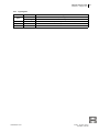
1
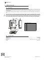
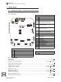
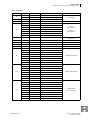
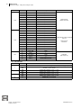
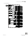
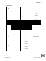
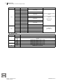
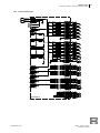
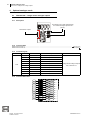
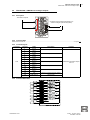
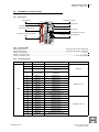
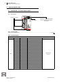
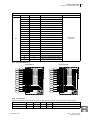
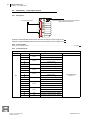
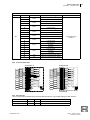
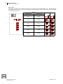
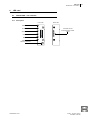
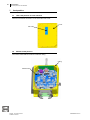
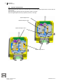
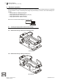
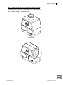
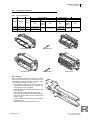
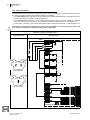
Installer manual
5
General instructions
1
Installer manual
1.1
General instructions
This manual aims at providing information to install the ARM receiving
unit of Autec Dynamic series radio remote controls.
Information about transmitting unit's actuators has been provided in this
manual for reference and/or applicative purposes. This does not authorise any modification of the transmitting unit.
Instructions regarding the use of the radio remote control are contained
in the “user manual” (provided together with the radio remote control).
This manual and the “user manual” must be read and understood in all
their parts by those who decide and/or carry out the radio remote control
installation.
ARM receiving unit
Always remember that:
- photos and drawings contained in this manual are useful examples that help understand its instructions and
warnings
- if necessary, contact Autec if any of the instructions and/or warnings given in this manual are not clear.
No part of this manual may be reproduced, in any form or by any means, without written permission of Autec (including recording and photocopying).
If this manual is lost or damaged, ask Autec for a copy. Please specify the serial number of the related radio remote
control.
All installation operations can only be carried out by qualified technicians who are suitably trained with respect to
the relevant norms and laws.
This manual integrates instructions provided by the manufacturer of the machine where the radio remote control is
to be installed.
As for instructions and warnings regarding the machine where the radio remote control is to be installed, follow the
instructions given in the machine's manual.
1.2
Symbol conventions
Three symbols are employed in this manual, which are used to highlight specific safety-related issues. They are
classified according to the hazardous situation that may arise and on the possible consequences:
If the highlighted instructions are not respected ...
Symbol
... a dangerous situation will
occur …
... consequences for people
may be …
... consequences for property
may be …
… very likely.
… critical
(death or physical damage).
… critical.
… probably.
… critical
(death or physical damage).
… critical.
… probably.
… moderate
(non-severe physical damage).
… moderate.
This symbol is also used, and it identifies texts to be read carefully.
Index
Back
LIIARM00E0-00.fm
AUTEC - Dynamic Series
Installer manual
6
ARM receiving unit
Description
2
ARM receiving unit
2.1
Description
The receiving unit communicates with the machine through digital and analogue outputs or over CANopen® communication protocol, that allows communication in a CAN bus network. The receiving unit acts as a slave node within this network.
All commands, including STOP and SAFETY, are sent via CAN network and also activate their corresponding outputs.
It is not possible to only rely on the CAN communication status to maintain or bring the remote controlled
machine to a safe condition. Messages sent by the radio remote control via CAN network do not in fact ensure the same safety features as the corresponding commands that are directly carried out by the receiving
unit's safety outputs. Please refer to chapters 12 and 11 for instructions to correctly wire such outputs.
D
E
F
G
C
B
A
H
G
2.2
A
148 mm (5.82 In)
B
116 mm (4.57 In)
C
253 mm (9.96 In)
D
antenna
E
LEDs
F
TEACH pushbutton
G
connector for cable control
H
plug
Technical data
Housing material ....................................................................................................................................................... PA6 (20% fg)
Antenna............................................................................................................................................................................ dedicated
Protection degree...................................................................................................................................................................... IP65
Dimensions ........................................................................................................................ 200 x 230 x 95 mm (7.9 x 9.1 x 3.8 In)
Weight ........................................................................................................................................................................ 3 kg (6.6 Lb)
Index
Back
AUTEC - Dynamic Series
Installer manual
LIIARM00E0-00.fm
ARM receiving unit
7
Exploded view
2.3
Exploded view
Cover
LED card
Optional analogue cards
Optional digital cards
Radio module
Address key
Data memory
Mother board
Casing
Antenna
Connector for cable control
Plug
Index
Back
LIIARM00E0-00.fm
AUTEC - Dynamic Series
Installer manual
8
Mother boards
FSAADV01A (voltage) - voltage-driven analogue outputs
3
Mother boards
3.1
FSAADV01A (voltage) - voltage-driven analogue outputs
3.1.1 Description
CONNECTORS
F1 J1
3
2
1
2
F2
1
7
1
4
S1
J2
JT1
9
3
F4
6
F3
J3
F5
DTK
IDK
JT12
JT8
BKK
JT7
JT6
JT2
JT13
JT15
JT14
1
4
1
4
J10
J6
6
JT5
Fused PWR+
J3
STOP and SAFETY outputs
J4
J13
J14
Digital outputs HO1-8 and LO1-8
J5
J6
J9
Digital outputs DO1-8
J7
J8
J10
Digital outputs DO9-16
J15
Voltage-driven analogue outputs AO1AO10 Digital outputs DO47-DO48
JT1
CAN BUS
JT2
LEDs on cover
JT3
Radio module
JT15
JT4
Cable control
JT5
Programming
JT6
IDK (address key)
2
JT7
BKK (backup data memory)
JT8
DTK (data memory)
1
2
J9
2
J2
1
5
5
8
6
5
8
2
1
1
J15
J5
1
J14
7
1
12
J13
5
1
10
6
10
J4
Power supply
JT3
JT4
2
J1
J8
1
J7
JT12 Optional digital cards
JT13
Optional analogue cards
JT14
FUSES
F1
SAF_2
F2
power supply
F3
STP_1
F4
STP_2
F5
SAF_1
DIP SWITCHES
S1
Group of 4 DIPs
3.1.2 Technical data
Power supply ..................................................................................................................................................................... 8-30 V
Absorbed power ........................................................................................................................................................................ 5 W
Protection of power supply (fuse F2) ......................................................................................................... 7.5 A (32 V , autofuse)
Outputs' maximum switching voltage ................................................................................................................................... 30 V
Rated current of STP_1 and STP_2 ......................................................................................................................... 7.5 A (30 V )
Protection of STP_1 (fuse F3) ................................................................................................................... 7.5 A (32 V , autofuse)
Protection of STP_2 (fuse F4) ................................................................................................................... 7.5 A (32 V , autofuse)
Rated current of SAF_1 ............................................................................................................................................ 7.5 A (30 V )
Protection SAF_1 (fuse F5) ....................................................................................................................... 7.5 A (32 V , autofuse)
Rated current of SAF_2 ............................................................................................................................................... 3 A (30 V )
Protection SAF_2 (fuse F1) .......................................................................................................................... 3 A (32 V , autofuse)
Index
Back
Rated current of digital outputs .................................................................................................................................... 4 A (30 V )
Rated current of analogue outputs .......................................................................................................................... 10 mA (28 V )
AUTEC - Dynamic Series
Installer manual
LIIARM00E0-00.fm
Mother boards
9
FSAADV01A (voltage) - voltage-driven analogue outputs
3.1.3 Pin layout
Connector
J1
Pin
Name
Description
1, 2
PWR-
negative
3
PWR+
positive
Function
Power supply
Plug
PE1, PE2
PWR-
negative
J2
1, 2
PWR+
protected positive
1
STP_1 IN
power supply positive terminal of STP_1
2
STP_1 OUT
output of STP_1
3
STP_2 IN
power supply positive terminal of STP_2
4
SAF_2 OUT
output of SAF_2
5, 6
STP_2 OUT
output of STP_2
7, 8
SAF_1 OUT
output of SAF_1
9
SAF_1 IN
power supply positive terminal of SAF_1
J4
1, 2
COM HO-LO
common wire
digital outputs HO1-8
and LO1-8
J5
1, 2
COM DO5-8
common wire
digital outputs DO5-8
J6
1, 2
COM DO1-4
common wire
digital outputs DO1-4
J7
1, 2
COM DO9-12
common wire
digital outputs DO9-12
J8
1, 2
COM DO13-16
common wire
digital outputs DO13-16
1
DO1
output DO1
2
DO2
output DO2
3
DO3
output DO3
4
DO4
output DO4
5
DO5
output DO5
6
DO6
output DO6
7
DO7
output DO7
J3
J9
J10
J13
8
DO8
output DO8
1
DO9
output DO9
2
DO10
output DO10
3
DO11
output DO11
4
DO12
output DO12
5
DO13
output DO13
6
DO14
output DO14
7
DO15
output DO15
8
DO16
output DO16
1
HO1
output HO1
2
LO1
output LO1
3
RESERVED
do not use
4
HO2
output HO2
5
LO2
output LO2
6
HO3
output HO3
7
LO3
output LO3
8
RESERVED
do not use
9
HO4
output HO4
10
LO4
output LO4
Fused PWR+
STOP
(see chapter 11)
SAFETY
(see chapter 12)
digital outputs DO1-8
digital outputs DO9-16
digital outputs
HO1-4 and LO1-4
Index
Back
LIIARM00E0-00.fm
AUTEC - Dynamic Series
Installer manual
10
Mother boards
FSAADV01A (voltage) - voltage-driven analogue outputs
Connector
J14
J15
JT1
Pin
Name
Description
1
HO5
output HO5
2
LO5
output LO5
3
RESERVED
do not use
4
HO6
output HO6
5
LO6
output LO6
6
HO7
output HO7
7
LO7
output LO7
8
RESERVED
do not use
9
HO8
output HO8
10
LO8
output LO8
1
AO1
output AO1
2
AO2
output AO2
3
AO3
output AO3
4
AO4
output AO4
5
AO5
output AO5
6
DO47
output DO47
7
AO6
output AO6
8
AO7
output AO7
9
AO8
output AO8
10
AO9
output AO9
11
AO10
output AO10
12
DO48
output DO48
1
CAN_GND
GND
2
CAN_L
L
3
CAN_SHLD
shield
4
CAN_H
H
5
CAN_T
line termination (120 Ω)
Function
digital outputs
HO5-8 and LO5-8
voltage driven analogue outputs
AO1-10
digital outputs
DO47-48
CAN BUS
(see chapter 14)
3.1.4 DIP switches
DIP
1
2
3
4
Position
Function
ON
enables the reverse recovery diode between SAF_1_OUT (cathode) and SAF_2_OUT (anode)
OFF
disables the reverse recovery diode between SAF_1_OUT (cathode)
and SAF_2_OUT (anode)
ON
enables filter capacitor on STP_1_OUT
OFF
disables filter capacitor on STP_1_OUT
ON
enables filter capacitor on STP_2_OUT
OFF
disables filter capacitor on STP_2_OUT
///
RESERVED: do not change
Index
Back
AUTEC - Dynamic Series
Installer manual
LIIARM00E0-00.fm
Mother boards
11
FSAADV01A (voltage) - voltage-driven analogue outputs
3.1.5 Technical data sheet
7.5A 30V
PWR+
PWR-
3
2
1
J1
PE1
PE2
2
1
J2
1
IN
7.5A 30V
STP_1
2
3
OUT
IN
AO1
AO2
AO3
AO4
AO5
AO6
AO7
AO8
AO9
AO10
1
2
3
4
5
7
8
9
10
11
D--D---
DO47
DO48
6
12
D--D--D--D--D--D--D--D---
HO1
LO1
HO2
LO2
HO3
LO3
HO4
LO4
D--D--D--D--D--D--D--D---
HO5
LO5
HO6
LO6
HO7
LO7
HO8
LO8
D--D--D--D--D--D--D--D---
DO1
DO2
DO3
DO4
DO5
DO6
DO7
DO8
D--D--D--D--D--D--D--D---
DO9
DO10
DO11
DO12
DO13
DO14
DO15
DO16
VOLT
VOLT
VOLT
VOLT
VOLT
VOLT
VOLT
VOLT
VOLT
VOLT
7.5A 30V
J15
STP_2
5
6
9
OUT
7
8
4
OUT
IN
A-A-A-A-A-A-A-A-A-A--
7.5A 30V
SAF_1
J13
OUT
3A 30V
J3
SAF_2
2
1
1
2
2
1
J14
J4
J5
J6
J9
1
2
J7
2
1
J8
J10
FSAADV01A
CAN_GND
CAN_L
CAN_SHLD
CAN_H
120Ω
CAN_T
JT1
1
2
4
5
6
7
9
10
3
8
1
2
4
5
6
7
9
10
3
8
1
2
3
4
5
6
7
8
1
2
3
4
5
6
7
8
1
2
3
4
5
Index
Back
LIIARM00E0-00.fm
AUTEC - Dynamic Series
Installer manual
12
Mother boards
FSAADP01A (PWM) - current-driven analogue outputs
3.2
FSAADP01A (PWM) - current-driven analogue outputs
3.2.1 Description
CONNECTORS
F1 J1
1
F2
2
3
7
1
4
S1
JT1
9
J3
F5
6
3
1
F3
F4
2
J2
DTK
IDK
JT12
JT8
BKK
JT7
JT6
JT2
JT13
JT15
JT14
JT3
J1
Power supply
J2
Fused PWR+
J3
STOP and SAFETY outputs
J4
J11
J12
PWM driven analogue outputs AO1-AO8
Voltage-driven analogue outputs AO9AO10 Digital outputs DO47-DO48
J5
J6
J9
Digital outputs DO1-8
J7
J8
J10
Digital outputs DO9-16
JT1
CAN BUS
JT2
LEDs on cover
Cable control
JT5
JT5
Programming
JT6
IDK (address key)
JT7
BKK (backup data memory)
JT8
DTK (data memory)
2
1
J7
1
2
1
5
6
4
J6
1
J10
1
4
1
8
5
8
2
1
5
J9
2
JT4
J12
1
J11
J5
JT4
7
1
6
10
2J4
12
JT3
Radio module
JT15
J8
JT12 Optional digital cards
JT13
Optional analogue cards
JT14
FUSES
F1
SAF_2
F2
power supply
F3
STP_1
F4
STP_2
F5
SAF_1
DIP SWITCH
S1
Group of 4 DIPs
3.2.2 Technical data
Power supply ..................................................................................................................................................................... 8-30 V
Absorbed power ........................................................................................................................................................................ 5 W
Protection of power supply (fuse F2) ......................................................................................................... 7.5 A (32 V , autofuse)
Outputs' maximum switching voltage ................................................................................................................................... 30 V
Rated current of STP_1 and STP_2 ......................................................................................................................... 7.5 A (30 V )
Protection of STP_1 (fuse F3) ................................................................................................................... 7.5 A (32 V , autofuse)
Protection of STP_2 (fuse F4) ................................................................................................................... 7.5 A (32 V , autofuse)
Rated current of SAF_1 ............................................................................................................................................ 7.5 A (30 V )
Protection SAF_1 (fuse F5) ....................................................................................................................... 7.5 A (32 V , autofuse)
Rated current of SAF_2 ............................................................................................................................................... 3 A (30 V )
Protection SAF_2 (fuse F1) .......................................................................................................................... 3 A (32 V , autofuse)
Rated current of digital outputs .................................................................................................................................... 4 A (30 V )
Rated current of analogue outputs ............................................................................................................................... 2 A (30 V )
Index
Back
AUTEC - Dynamic Series
Installer manual
LIIARM00E0-00.fm
Mother boards
13
FSAADP01A (PWM) - current-driven analogue outputs
3.2.3 Pin layout
Connector
J1
Pin
Name
Description
1, 2
PWR-
negative
3
PWR+
positive
Function
Power supply
Plug
PE1, PE2
PWR-
negative
J2
1, 2
PWR+
protected positive
1
STP_1 IN
power supply positive terminal of STP_1
2
STP_1 OUT
output of STP_1
3
STP_2 IN
power supply positive terminal of STP_2
4
SAF_2 OUT
output of SAF_2
5, 6
STP_2 OUT
output of STP_2
7, 8
SAF_1 OUT
output of SAF_1
9
SAF_1 IN
power supply positive terminal of SAF_1
J4
1, 2
COM AO1-AO8
common wire
PWM driven analogue outputs
AO1-8
J5
1, 2
COM DO5-8
common wire
digital outputs DO5-8
J6
1, 2
COM DO1-4
common wire
digital outputs DO1-4
J7
1, 2
COM DO9-12
common wire
digital outputs DO9-12
J8
1, 2
COM DO13-16
common wire
digital outputs DO13-16
1
DO1
output DO1
2
DO2
output DO2
3
DO3
output DO3
4
DO4
output DO4
5
DO5
output DO5
6
DO6
output DO6
7
DO7
output DO7
J3
J9
J10
J11
8
DO8
output DO8
1
DO9
output DO9
2
DO10
output DO10
3
DO11
output DO11
4
DO12
output DO12
5
DO13
output DO13
6
DO14
output DO14
7
DO15
output DO15
output DO16
8
DO16
1
AO4 L
2
AO4 H
3
AO1 L
4
AO1 H
5
RESERVED
6
AO3 H
7
AO3 L
8
AO2 H
9
AO2 L
10
RESERVED
Fused PWR+
STOP
(see chapter 11)
SAFETY
(see chapter 12)
digital outputs DO1-8
digital outputs DO9-16
output AO4
output AO1
do not use
PWM driven analogue outputs
AO1-4
output AO3
output AO2
do not use
Index
Back
LIIARM00E0-00.fm
AUTEC - Dynamic Series
Installer manual
14
Mother boards
FSAADP01A (PWM) - current-driven analogue outputs
Connector
J12
JT1
Pin
Name
1
AO8 L
2
AO8 H
3
AO9
4
AO5 L
5
AO5 H
6
DO47
7
AO7 H
8
AO7 L
9
AO10
10
AO6 H
11
AO 6L
Description
Function
output AO8
output AO9
output AO5
output DO47
PWM driven analogue outputs
AO5-8
voltage driven analogue outputs
AO9-10
output AO7
output AO10
digital outputs
DO47-48
output AO6
12
DO48
output DO48
1
CAN_GND
GND
2
CAN_L
L
3
CAN_SHLD
shield
4
CAN_H
H
5
CAN_T
line termination (120 Ω)
CAN BUS
(see chapter 14)
3.2.4 DIP switches
DIP
1
2
3
4
Position
Function
ON
enables the reverse recovery diode between SAF_1_OUT (cathode) and SAF_2_OUT (anode)
OFF
disables the reverse recovery diode between SAF_1_OUT (cathode) and SAF_2_OUT
(anode)
ON
enables filter capacitor on STP_1_OUT
OFF
disables filter capacitor on STP_1_OUT
ON
enables filter capacitor on STP_2_OUT
OFF
disables filter capacitor on STP_2_OUT
///
RESERVED: do not change
Index
Back
AUTEC - Dynamic Series
Installer manual
LIIARM00E0-00.fm
Mother boards
15
FSAADP01A (PWM) - current-driven analogue outputs
3.2.5 Technical data sheet
7.5A 30V
PWR+
PWR-
3
2
1
A--
J1
PE1
A--
PE2
A--
2
1
J2
1
IN
A--
PWR
PWM
PWR
PWM
PWR
PWM
PWR
PWM
7.5A 30V
H
L
H
L
H
L
H
L
AO1
AO2
AO3
AO4
STP_1
2
3
OUT
IN
J11
7.5A 30V
A-STP_2
5
6
9
A--
OUT
IN
A-7.5A 30V
SAF_1
7
8
4
4
3
8
9
6
7
2
1
10
5
A--
PWR
PWM
PWR
PWM
PWR
PWM
PWR
PWM
OUT
A-- VOLT
A-- VOLT
OUT
3A 30V
J3
SAF_2
D--D---
AO9
AO10
5
4
10
11
7
8
2
1
3
9
DO47
DO48
6
12
H
L AO5
H
L AO6
H
L AO7
H
L AO8
J12
2
1
1
2
2
1
1
2
J4
J5
D--D--D--D---
DO1
DO2
DO3
DO4
1
2
3
4
D--D--D--D---
DO5
DO6
DO7
DO8
5
6
7
8
J9
J6
J7
2
1
J8
D--D--D--D---
DO9
DO10
DO11
DO12
1
2
3
4
D--D--D--D---
DO13
DO14
DO15
DO16
5
6
7
8
J10
FSAADP01A
CAN_GND
CAN_L
CAN_SHLD
CAN_H
120Ω
CAN_T
JT1
1
2
3
4
5
Index
Back
LIIARM00E0-00.fm
AUTEC - Dynamic Series
Installer manual
16
Optional analogue cards
FSAAVO10A - voltage driven analogue outputs
4
Optional analogue cards
4.1
FSAAVO10A - voltage driven analogue outputs
4.1.1 Description
Connectors to the mother board (below)
or to another analogue optional card
(above).
Terminals for outputs
4.1.2 Technical data
Rated current of AO1-4 ........................................................................................................................................... 100 mA (3 V)
Rated current of AO7-12 ......................................................................................................................................... 10 mA (28 V )
4.1.3 Terminals layout
Connector
Terminal
Name
Description
1
AO1
output AO1
J18
2
AO2
output AO2
3
AO3
output AO3
4
AO4
output AO4
5
AO7
output AO7
6
AO8
output AO8
7
AO9
output AO9
8
AO10
output AO10
9
AO11
output AO11
10
AO12
output AO12
Function
voltage driven analogue outputs
AO1-4 and AO7-12
4.1.4 Technical data sheet
1
AO1
2
AO2
3
AO3
4
AO4
5
AO7
6
AO8
7
AO9
8
AO10
9
AO11
10
AO12
HICUR
VOLT
HICUR
VOLT
HICUR
VOLT
HICUR
VOLT
VOLT
VOLT
VOLT
VOLT
J18
VOLT
VOLT
A--A--A--A--A--A--A--A--A--A---
FSAAVO10A
Index
Back
AUTEC - Dynamic Series
Installer manual
LIIARM00E0-00.fm
Optional analogue cards
17
FSAAPO06A - PWM driven analogue outputs
4.2
FSAAPO06A - PWM driven analogue outputs
4.2.1 Description
Terminals for outputs
Connectors to the mother board (below) or to
another analogue optional card (above).
4.2.2 Technical data
Rated current of AO7-12 .............................................................................................................................................. 2 A (30 V )
4.2.3 Terminals layout
Connector
J19
Terminal
Name
1
AO7 H
Description
Function
2
AO7 L
3
AO8 H
4
AO8 L
5
AO9 H
6
AO9 L
7
AO10 H
8
AO10 L
9
AO11 H
10
AO11 L
11
AO12 H
12
AO12 L
13
CD
common of reverse recovery diodes
14
COM AO7-12
common wire
output AO7
output AO8
output AO9
PWM driven analogue outputs
AO7-12
output AO10
output AO11
output AO12
4.2.4 Technical data sheet
1
2
3
4
5
6
7
8
9
10
11
12
13
14
H
PWR
AO7 L
PWM
H
AO8 L
H
AO9 L
PWR
PWM
PWR
PWM
H
AO10 L
PWM
H
PWR
AO11 L
PWM
H
AO12 L
PWR
PWR
A-A-A-A-A-A--
PWM
CD
J19
FSAAPO06A
Index
Back
LIIARM00E0-00.fm
AUTEC - Dynamic Series
Installer manual
18
Optional analogue cards
FSAAPO06A - PWM driven analogue outputs
4.2.5 Pads
If optional card FSAAPO06A is installed in another ARM receiving unit with mother board FSAADP01A, pad groups
SP2 and SP3 shall not be short-circuited.
Index
Back
AUTEC - Dynamic Series
Installer manual
LIIARM00E0-00.fm
Optional analogue cards
19
FSAAMI01A - analogue inputs
4.3
FSAAMI01A - analogue inputs
4.3.1 Description
DIP switches
Reserved connector
Connector for programming
Terminals for serial port
LEDs
Terminals for digital inputs
Connector for data memory
Connectors to the mother board (below) or to another analogue optional card (above).
Terminals for digital or analogue
inputs
4.3.2 Technical data
RS485 serial interface ....................................................................................................... according to the standard TIA/EIA-485
RS232 serial interface ....................................................................................................... according to the standard TIA/EIA-232
Voltage on digital inputs .................................................................................................................................................. 5 - 30 V
Voltage on analogue inputs ............................................................................................................................................. 0 - 10 V
Current on analogue inputs ...................................................................................................................... 4 - 20 mA (Ri=320Ohm)
4.3.3 Terminals layout
Connector
J20
Terminal
Name
Description
1
GND SER
GND
2
232RX
RX (RS232)
3
232TX 485A
TX (RS232)
A (RS485)
4
232CTS 485B
CTS (RS232)
B (RS485)
5
DIG IN 1
digital input 1
6
DIG IN 2
digital input 2
7
DIG IN 3
digital input 3
8
DIG IN 4
digital input 4
9
DIG IN 5
digital input 5
10
DIG IN 6
digital input 6
11
DIG IN 7
digital input 7
12
DIG IN 8
digital input 8
13
GND DIG
GND (digital inputs 1-8)
14
ANL IN 1
analogue input 1
15
ANL IN 2
analogue input 2
16
ANL IN 3
analogue input 3
17
ANL IN 4
analogue input 4
18
ANL IN 5
analogue input 5
19
ANL IN 6
analogue input 6
20
ANL IN 7
analogue input 7
21
ANL IN 8
analogue input 8
22
GND ANL
GND (analogue inputs 1-8)
Function
serial port
digital inputs 1-8
analogue inputs 1-8
Index
Back
LIIARM00E0-00.fm
AUTEC - Dynamic Series
Installer manual
20
Optional analogue cards
FSAAMI01A - analogue inputs
4.3.4 Technical data sheet
GND_SER
232RX
232TX_485A
232CTS_485B
1
2
3
4
5
6
7
8
9
10
11
12
13
DIG_IN_1
DIG_IN_2
DIG_IN_3
DIG_IN_4
DIG_IN_5
DIG_IN_6
DIG_IN_7
DIG_IN_8
GND_DIG
14
15
16
17
18
19
20
21
22
ANL_IN_1
ANL_IN_2
ANL_IN_3
ANL_IN_4
ANL_IN_5
ANL_IN_6
ANL_IN_7
ANL_IN_8
GND_ANL
J20
FSAAMI01A
4.3.5 DIP switches
DIP
1
Position
Function
ON
RS232
OFF
RS485
2
ON/OFF
not used
3
ON/OFF
not used
ON
RS485 termination enabled
OFF
RS485 termination disabled
4
4.3.6 Pads
Pad groups on the back of the card are used to set analogue inputs either as current driven or voltage driven inputs.
If you short-circuit pads 1-2 of both groups of a given input, you will obtain a current driven input; on the contrary,
if you want to obtain a voltage driven input, you need to short circuit pads 2-3.
Analogue input
Current input
Voltage input
ANL IN 1
ANL IN 2
ANL IN 3
ANL IN 4
ANL IN 5
ANL IN 6
ANL IN 7
ANL IN 8
Index
Back
AUTEC - Dynamic Series
Installer manual
LIIARM00E0-00.fm
Optional analogue cards
21
FSAAMI01A - analogue inputs
4.3.7 Light signals
LEDs
green
Position
Meaning
off
no power supply
blinking
card is working
red
on
data memory is missing or error on the memory
yellow
on
set-up mode
blue
///
not used
Index
Back
LIIARM00E0-00.fm
AUTEC - Dynamic Series
Installer manual
22
Optional digital cards
FSADSO16A - solid state digital outputs
5
Optional digital cards
5.1
FSADSO16A - solid state digital outputs
5.1.1 Description
Terminals for outputs
DIP switches
Connector to the mother board (below) or to another digital optional
card (above).
5.1.2 Technical data
Rated current of digital outputs .................................................................................................................................... 4 A (30 V )
5.1.3 Terminals layout
Configuration A
Connector
Terminal
J16
Name
Description
1
DO17
output DO17
2
DO18
output DO18
3
DO19
output DO19
4
DO20
output DO20
5
DO21
output DO21
6
DO22
output DO22
7
DO23
output DO23
8
DO24
output DO24
9
DO25
output DO25
10
DO26
output DO26
11
DO27
output DO27
12
DO28
output DO28
13
DO29
output DO29
14
DO30
output DO30
15
DO31
output DO31
16
DO32
output DO32
17
COM DO29-32
common DO29-32
18
COM DO25-28
common DO25-28
19
COM DO21-24
common DO21-24
20
COM DO17-20
common DO17-20
21
CD
common of reverse recovery diodes
22
CD
common of reverse recovery diodes
Function
digital outputs
DO17-32
Index
Back
AUTEC - Dynamic Series
Installer manual
LIIARM00E0-00.fm
Optional digital cards
23
FSADSO16A - solid state digital outputs
Configuration B
Connector
J16
Terminal
Name
Description
1
DO33
output DO33
2
DO34
output DO34
3
DO35
output DO35
4
DO36
output DO36
5
DO37
output DO37
6
DO38
output DO38
7
DO39
output DO39
8
DO40
output DO40
9
DO41
output DO41
10
DO42
output DO42
11
DO43
output DO43
12
DO44
output DO44
13
DO45
output DO45
14
DO46
output DO46
15
DO47
output DO47
Function
digital outputs
DO33-48
16
DO48
output DO48
17
COM DO45-48
common DO45-48
18
COM DO41-44
common DO41-44
19
COM DO37-40
common DO37-40
20
COM DO33-36
common DO33-36
21
CD
common of reverse recovery diodes
22
CD
common of reverse recovery diodes
5.1.4 Technical data sheet
Configuration A
DO17
DO18
DO19
DO20
DO21
DO22
DO23
DO24
DO25
DO26
DO27
DO28
DO29
DO30
DO31
DO32
1
2
3
4
5
6
7
8
9
10
11
12
13
14
15
16
17
18
19
20
21
22
Configuration B
D--D--D--D--D--D--D--D--D--D--D--D--D--D--D--D---
CD
CD
ON
J16
OFF
1 2 3 4
FSADSO16A
1
2
3
4
5
6
7
8
9
10
11
12
13
14
15
16
DO33
DO34
DO35
DO36
DO37
DO38
DO39
DO40
DO41
DO42
DO43
DO44
DO45
DO46
DO47
DO48
17
18
19
20
21
22
CD
CD
ON
J16
OFF
D--D--D--D--D--D--D--D--D--D--D--D--D--D--D--D---
1 2 3 4
FSADSO16A
5.1.5 DIP switches
The two configurations indicated in the technical data sheet are the only possible settings for DIP switches.
DIP 1
DIP 2
DIP 3
DIP 4
Function
Configuration A
ON
ON
OFF
OFF
card outputs are DO17-32
Configuration B
OFF
OFF
ON
ON
card outputs are DO33-48
Index
Back
LIIARM00E0-00.fm
AUTEC - Dynamic Series
Installer manual
24
Optional digital cards
FSADRO08_ - relay digital outputs
5.2
FSADRO08_ - relay digital outputs
5.2.1 Description
Terminals for outputs
Connector to the mother board (below) or to another
digital optional card (above).
Optional card FSADRO08A shall be used when the receiving unit power supply is 24 V .
Optional card FSADRO08B shall be used when the receiving unit power supply is 12 V .
5.2.2 Technical data
Rated current of digital outputs .................................................................................................................................... 4 A (30 V )
5.2.3 Terminals layout
Configuration A
Connector
Terminal
1
Name
DO17
2
3
DO18
DO19
J17
DO20
NC or NO DO20a
common DO20
DO21
10
11
NC or NO DO19a
common DO19
8
9
NC or NO DO18a
common DO18
6
7
NC or NO DO17
NC or NO DO21a
common DO21
DO22
NC or NO DO22a
12
common DO22
13
common DO23
14
DO23
15
relay digital outputs
DO17-24
NC DO23
NO DO23
16
17
Function
a
common DO17
4
5
Description
common DO24
DO24
NC DO24
19
CD
common of reverse recovery diodes
20
CD
common of reverse recovery diodes
18
NO DO24
a. NC or NO depends on how pads have been short-circuited (see paragraph 5.2.6)
Index
Back
AUTEC - Dynamic Series
Installer manual
LIIARM00E0-00.fm
Optional digital cards
25
FSADRO08_ - relay digital outputs
Configuration B
Connector
Terminal
Name
1
Description
NC or NO DO25
DO25
2
common DO25
3
NC or NO DO26a
DO26
4
common DO26
5
NC or NO DO27a
DO27
6
common DO27
7
NC or NO DO28a
DO28
8
common DO28
9
J17
Function
a
NC or NO DO29a
DO29
10
relay digital outputs
DO25-32
common DO29
11
NC or NO DO30a
DO30
12
common DO30
13
common DO31
14
DO31
NC DO31
15
NO DO31
16
common DO32
17
DO32
NC DO32
19
CD
common of reverse recovery diodes
20
CD
common of reverse recovery diodes
18
NO DO32
a. NC or NO depends on how pads have been short-circuited (see paragraph 5.2.6)
5.2.4 Technical data sheet
Configuration A
1
2
3
4
5
6
7
8
9
10
11
12
13
14
15
16
17
18
19
20
Configuration B
DO17
D---
DO18
D---
DO19
D---
DO20
D---
DO21
D---
DO22
D---
1
2
3
4
5
6
7
8
9
10
11
12
13
14
15
16
17
18
19
20
DO23
D---
DO24
D---
1 2
ON
CD
CD
OFF
J17
DO25
D---
DO26
D---
DO27
D---
DO28
D---
DO29
D---
DO30
D---
DO31
D---
DO32
D---
1 2
ON
CD
CD
OFF
J17
FSADRO08_
FSADRO08_
5.2.5 DIP switches
The two configurations indicated in the technical data sheet are the only possible settings for DIP switches.
DIP 1
DIP 2
Function
Configuration A
ON
OFF
card outputs are DO17-24
Configuration B
OFF
ON
card outputs are DO25-32
Index
Back
LIIARM00E0-00.fm
AUTEC - Dynamic Series
Installer manual
26
Optional digital cards
FSADRO08_ - relay digital outputs
5.2.6 Pads
Pad groups on the back of the card are used to set outputs DO17-22 (configuration A) or outputs DO25-30
(configuration B) either as NC or NO. Short-circuit pads 1-2 to have an NC output; on the contrary, short-circuit pads
2-3 to have an NO output.
Output
Configuration A
Configuration B
DO17
DO25
DO18
DO26
DO19
DO27
DO20
DO28
DO21
DO29
DO22
DO30
NC
NO
Index
Back
AUTEC - Dynamic Series
Installer manual
LIIARM00E0-00.fm
LED card
27
FSADLS06A - user interface
6
LED card
6.1
FSADLS06A - user interface
6.1.1 Description
Front view
Back view
POWER LED
ALARM LED
STATUS LED
Connector for the
connection to the mother
board
RUN LED
ERR LED
SETUP LED
TEACH pushbutton
Index
Back
LIIARM00E0-00.fm
AUTEC - Dynamic Series
Installer manual
28
Card position
LED card position for user interface
7
Card position
7.1
LED card position for user interface
The LED card shall be screwed in on the inner side of the cover.
Cover
LED card
7.2
Mother board position
The mother board shall be screwed in inside the casing.
casing
Mother board
Index
Back
AUTEC - Dynamic Series
Installer manual
LIIARM00E0-00.fm
Card position
29
Address key and data memory position
7.3
Address key and data memory position
The address key and the data memory shall be connected to the mother board through connectors JT6 (IDK) and
JT8 (DTK) respectively and they shall be fastened with their screw.
Mother board
Data memory
Address key
7.4
Radio module position
The radio module shall be connected to the mother board through connectors JT3 and JT15 on the mother board
and it shall be fastened with its four screws.
Mother board
Radio module
Index
Back
LIIARM00E0-00.fm
AUTEC - Dynamic Series
Installer manual
30
Card position
Optional cards position
7.5
Optional cards position
ARM receiving unit may contain up to 4 optional cards, two of them with digital outputs and two of them with analogue outputs.
Up to two analogue optional cards may be placed, stacked, on the left.
Up to two digital optional cards may be placed, stacked, on the right.
Optional digital card 2
Optional analogue card 2
Optional analogue card 1
Optional digital card 1
Index
Back
AUTEC - Dynamic Series
Installer manual
LIIARM00E0-00.fm
Light signals
31
POWER LED (green)
8
Light signals
The ARM receiving unit has six LEDs:
- POWER is green
- ALARM is red
- STATUS is blue
- RUN is green
- ERR is red
- SETUP is yellow.
8.1
POWER LED (green)
The POWER LED indicates the status of the receiving unit and of the radio link.
The POWER LED ...
... is off
Meaning
The receiving unit is switched off.
... blinks slowly
Radio link has been built.
... is on
8.2
No radio link.
ALARM LED (red)
The ALARM LED warns about anomalies in the receiving unit.
The ALARM LED ...
... is off
Meaning
The receiving unit works correctly.
... repeats the sequence: a slow blink and a pause
Error on the STOP outputs.
... repeats the sequence: two slow blinks and a pause
Error on the SAFETY outputs.
... repeats the sequence: three slow blinks and a pause
Error on the outputs corresponding to direction commands.
... is on
The receiving unit does not work correctly.
Index
Back
LIIARM00E0-00.fm
AUTEC - Dynamic Series
Installer manual
32
Light signals
STATUS LED (blue)
8.3
STATUS LED (blue)
The STATUS LED warns about anomalies on the outputs or on the power supply and indicates the reception of
data from the transmitting unit.
The STATUS LED ...
... is off
Meaning
No radio link.
... blinks slowly
Over-voltage on power supply.
... blinks fast
The receiving unit receives data from the transmitting unit.
... is on
8.4
Over-current in one of the PWM analogue outputs.
RUN LED (green)
RUN LED signals reflect the guidelines of the CANopen® standard, CiA recommendation 303-3. Terms used in the
following table are therefore consistent with such recommendation.
The RUN LED indicates the status of the application layer (CANopen node).
The RUN LED ...
... is off
Meaning
The CAN node is off:
the receiving unit is switched off or is performing a reset
... blinks fast
The CAN node does not send commands on the network:
configuration through the LSS services is in progress
... blinks slowly
The CAN node does not send commands on the network:
the receiving unit is in state PREOPERATIONAL
... repeats the sequence: a slow blink and a pause
The CAN node does not send commands on the network:
the receiving unit is in state STOPPED
... is on
8.5
The CAN node is working correctly:
the receiving unit is in state OPERATIONAL
ERR LED (red)
ERR LED signals reflect the guidelines of the CANopen® standard, CiA recommendation 303-3. Terms used in the
following table are therefore consistent with such recommendation.
The ERR LED indicates the status of the (CAN bus) physical layer and errors due to wrong configurations.
The ERR LED ...
... is off
Meaning
No operating problems.
... blinks fast
CAN communication is not available:
configuration through the LSS services is in progress
Index
Back
AUTEC - Dynamic Series
Installer manual
LIIARM00E0-00.fm
Light signals
33
SETUP LED (yellow)
The ERR LED ...
Meaning
... blinks slowly
CAN communication does not work correctly:
configuration errors on the receiving unit.
... repeats the sequence: a slow blink and a pause
CAN communication does not work correctly:
at least one of the frame error counters has reached the
warning level.
... repeats the sequence: two slow blinks and a pause
CAN communication does not work correctly:
a "heartbeat event" or a "guard event" has occurred.
... repeats the sequence: three slow blinks and a pause
... is on
8.6
CAN communication does not work:
the SYNC message has not been received within the configured communication cycle period time out.
CAN communication does not work:
the CAN controller is bus off.
SETUP LED (yellow)
The SETUP LED shows the status of the data memory and of the address key, depending on the receiving unit's
working status.
The ALARM LED ...
... is off
Meaning
The receiving unit works correctly.
... repeats the sequence: a slow blink and a pause
Error on the address key.
... repeats the sequence: two slow blinks and a pause
Error on the data memory.
... repeats the sequence: three slow blinks and a pause
Calibration of the rest position values for proportional outputs is being performed within the REMOTE SETUP procedure.
... repeats the sequence: three fast blinks and a pause
The receiving unit is storing data set through the
“REMOTE SETUP” or through the “Data memory backup”.
... repeats the sequence: four slow blinks and a pause
Inversion of movement direction of the joysticks axis is
being performed within the REMOTE SETUP procedure.
... blinks slowly
A data memory is connected to the BKK connector.
... blinks fast
This signal may have one of the following meanings,
depending on the operations the receiving unit is performing:
- two analogue commands are being activated simultaneously during the “REMOTE SETUP” procedure
- the receiving unit is restoring factory settings
- an error occurred during the “Data memory backup”.
Index
... is on
LIIARM00E0-00.fm
The receiving unit is in “REMOTE SETUP” mode.
AUTEC - Dynamic Series
Installer manual
Back
34
Electrical connection
Housing for plugs (male insert) on the casing
9
Electrical connection
Only use the provided connectors and terminals for electrical connections inside the ARM receiving unit. Depending
on the connectors, to carry out receiving unit's wiring it may be necessary to connect a wire to the following components:
- a screw terminal on a Harting 32-pole plug
- a screw terminal on a Phoenix connector
- a crimp-style terminal on a Harting 50- or 72-pole plug
- a crimp-style terminal on a Tyco connector
- a crimp-style terminal on a Molex connector
Wires to be connected shall be stripped of as shown below.
9.1
Housing for plugs (male insert) on the casing
9.1.1 Bulkhead mounting of Harting 32- and 50-pole plug
09 20 032 0301
9.1.2 Bulkhead mounting of Harting 72-pole plug
Index
09 30 016 0301
Back
AUTEC - Dynamic Series
Installer manual
LIIARM00E0-00.fm
Electrical connection
35
Housing for socket mounting (female insert) on the cable
9.2
Housing for socket mounting (female insert) on the cable
There are different kinds of hoods; one example for each model is listed here
9.2.1 Hood for Harting 32- and 50-pole socket
09 20 032 0420
9.2.2 Hood for Harting 72-pole socket
09 30 016 0521
Index
Back
LIIARM00E0-00.fm
AUTEC - Dynamic Series
Installer manual
36
Electrical connection
Screw terminals
9.3
Screw terminals
9.3.1 Harting 32-pole plug
Brand
Model
No. of
poles
Plug (on casing)
Socket (cable)
Harting
HAN 32 A
32
(1-16) 09 20 016 2612
(17-32) 09 20 016 2613
(1-16) 09 20 016 2812
(17-32) 09 20 016 2813
09 20 016 2612
09 20 016 2812
09 20 016 2613
09 20 016 2813
9.3.2 Phoenix connector
Brand
No. of poles
Type
Order number
4
MC 1,5/4-ST-3,5
1840382
6
MC 1,5/6-ST-3,5
1840405
8
MC 1,5/8-ST-3,5
1840421
9
MC 1,5/9-ST-3,5
1840434
10
MC 1,5/10-ST-3,5
1840447
Phoenix
1840382
1840405
1840421
1840434
1840447
Index
Back
AUTEC - Dynamic Series
Installer manual
LIIARM00E0-00.fm
Electrical connection
37
Crimp-style terminals
9.4
Crimp-style terminals
9.4.1 50- or 72-pole plug
Plug (on casing)
Brand
Model
No. of
poles
Connector
Art.
Socket (cable)
Crimp-style terminal
Wire
section
Art.
[mm2]
Harting
Harting
HAN 50 D
HAN 72 DD
50
09 21 025 3001 0.5 mm2
72
mm2
09 16 072 3001 1.0
Connector
Art.
Crimp-style terminal
Wire
section
Art.
[mm2]
09 15 000 6103
09 15 000 6102
09 21 025 3101 0.5 mm2
09 16 072 3101 1.0 mm2
09 15 000 6203
09 15 000 6202
09 21 025 3001
09 15 000 61xx
09 21 025 3101
09 16 072 3001
09 15 000 62xx
09 16 072 3101
Wire crimping
Use the specific Harting hand crimp tool to crimp
wires to be connected to 50- or 72-pole connectors.
The following instructions refer to Harting hand
crimp tool part number 09 99 000 0110.
- Grip the hand crimp tool securely and squeeze,
ratcheting the mechanism until it bottoms out.
Then allow it to open completely.
- Insert the terminal in the appropriate hole on the
hand crimp tool.
- Insert the pre-stripped wire into the terminal.
- Hold the wire and make sure that its isolation bottoms out in the terminal hole, then hold the hand
crimp tool tight.
- Complete the crimp by squeezing the tool until the
ratchet releases.
- Remove the terminated wire from the tool.
Index
Back
LIIARM00E0-00.fm
AUTEC - Dynamic Series
Installer manual
38
Electrical connection
Crimp-style terminals
Inserting the terminated wire in the connector
Insert the terminated wire in the corresponding connector cavity.
We suggest to use a specific tool, Harting art. 09 99 000 0059, to insert 0.5 mm2 section terminated wires.
Terminals shall be inserted from the wiring side and shall be pushed until they bottom out.
Complete terminal insertion by pushing the terminated wire through the cavity until you hear a "click". Verify proper
terminal seating with a light tug on the wire.
9.4.2 Tyco connector
Plug
Brand
Series
Connector
No. of poles
Art.
2
1-480698-0
3
1-480700-0
9
1-480706-0
Universal
MATE-N-LOK
Tyco Electronics
1-480698-0
Crimp-style terminal
Art.
350536-1
1-480706-0
1-480700-0
9.4.3 Molex connector
Plug
Brand
Connector
Series
No. of
poles
Molex
Molex
Index
Model
8
Mini Fit
Molex
39-01-2080
10
12
Crimp-style terminal
Part
Model
Art.
5556
39-00-0038
39-01-2080
5557
39-02-2100
39-02-2120
39-01-2100
39-02-2120
Back
AUTEC - Dynamic Series
Installer manual
LIIARM00E0-00.fm
Warnings for installation
39
General
10 Warnings for installation
The radio remote control can only be installed and tested by competent staff that masters the technical knowledge
required to carry out such procedure and is qualified according to the regulation of the country where the radio remote control is mounted.
Only if the radio remote control is installed correctly can it be used safely.
Besides instructions established by the machine's manufacturers, installers must always observe the following
warnings.
Never connect power supply positive pole to the outputs. Such connection would exclude the UMFS and
STOP safety functions. In this case the machine may be in a dangerous condition, out of the user's control.
The installer or the machine's manufacturer must avoid that a power supply positive pole is connected to
the outputs.
10.1 General
Respect and enforce the provisions of all reference standards relevant in the concerned application field
(i.e. IEC 60204-32 for hoisting machines.)
Always follow the instructions provided in the “technical data sheet” and respect values given in the technical data to carry out correct installation.
Due to the characteristics of radio propagation (i.e.: EM interference, near out-of-range condition), a delay
up to the "Passive stop time" may occasionally occur from the moment a command in the transmitting unit
is released to the moment its corresponding output in the receiving unit is deactivated.
With regards to the SAFETY outputs only (SAF_1 and SAF_2), a regular deactivation delay (approx. 1 second) applied to such outputs may add to this time.
Those who decide upon the installation of the radio remote control must make sure that these delays never
lead to a dangerous situation in the specific uses.
10.2 Mounting and fastening the receiving unit in the best position
Place the receiving unit so as to avoid incidental contact.
Place the receiving unit so that it can be easily reached in case of need.
Place the receiving unit so that it can be easily reached, and far from heat sources (i.e. exhaust pipes, heat
exchangers, radiators).
Place the receiving unit vertically, with the plug facing down.
Fix the receiving unit in four points, using the specific holes in the housing.
Do not perforate the receiving unit in any case.
It is recommended to use the appropriate vibration dampers when installing the system on machines that
produce strong vibrations.
10.3 Mounting and fastening the antenna in the best position
Install the antenna so that shields, structures or materials do not obstruct the radio link; in particular:
- the antenna shall not be placed inside closed metal containers
- the antenna must be installed in a vertical position, and possibly in sight of the work area
- the antenna must be placed at least 50 cm far from metal objects in its surroundings.
If these warnings are disregarded, the typical working range of the radio remote control may be reduced.
LIIARM00E0-00.fm
AUTEC - Dynamic Series
Installer manual
Index
Back
40
Warnings for installation
Wiring
The appropriate extension kit for the antenna may be used, in order to abide by the above-mentioned indications. In this case, place the antenna as far as possible from the receiving unit and from other electrical
and electronic devices.
10.4 Wiring
Wiring inside the receiving unit shall be made with electrical wires resistant to at least 125°C usage temperature.
Group wiring according to the following indications:
1. all wires connected to the same connector must be grouped together
2. all wires connected to connectors J1 to J8 on the mother board must be grouped together
3. all groups of wires shall be far from the radio module, in order to avoid interference and dangers related
to electrical safety.
Make sure that the receiving unit's power supply is protected against short circuits and is supplied either
by a battery or by a power supply unit with safety isolating transformer.
The power supply of the receiving unit must have a switch that allows power supply disconnection during
installation, wiring and/or maintenance operations. Connect the receiving unit immediately downstream of
the machine main switch or of the electrical panel main switch (see paragraph 13).
Pay special attention to the currents flowing in outputs SAF_1, SAF_2, STP_1 and STP_2: they shall not
exceed the maximum permitted values (see paragraphs 3.1.2 and 3.2.2).
The current of STOP outputs is interrupted at regular intervals for approx. 1 ms every 100 ms. If STOP outputs are used to power electronic devices, check that they are compatible with this recurring interruption
(use suitable filters if necessary).
If STOP outputs are connected in series with SAFETY outputs, set DIP 3 on the mother board in the ON
position.
10.5 At end of installation
Make sure that during installation the safety mechanisms on the radio remote control and/or in the machine
have not been made ineffective by possible procedures carried out.
Correctly close the receiving unit so that the protection degree from dust and water is not jeopardised:
check that the gasket is intact, correctly put the housing parts one over the other so that they overlap, and
screw in the screws.
10.6 Testing
After installation and wiring, test the system “machine+radio remote control”, and check that the operations carried out correspond exactly to the commands sent (in particular check the STOP command).
Make sure that outputs SAF_1 and SAF_2 only activate after the radio remote control start up.
The installer must check and complete the "Technical Data Sheet" in all its parts, adding the date the system has
been put into service, his stamp and signature.
In case of malfunction, disable the system “machine+radio remote control” until the problem has been
completely solved.
Index
Back
AUTEC - Dynamic Series
Installer manual
LIIARM00E0-00.fm
STOP outputs
41
Stop function complying with cat. 4 PL=e and SIL 3
11 STOP outputs
Outputs STP_1 and STP_2 are enabled by the STOP command.
STP_1_IN and STP_2_IN shall always receive power supply between 8 and 30 V , even though the corresponding
outputs STP_1 and STP_2 are not used.
The current of STOP outputs is interrupted at regular intervals for approx. 1 ms every 100 ms. Risk analysis
must consider this interruption.
If failure not related to the ARM receiving unit occurs (i.e. short circuit between STP_2_IN and STP_2_OUT)
and if DIP_2 and/or DIP_3 in the mother board are in the ON position (even by mistake or due to failure),
the filter capacitors (1000 μF) may cause a further delay in de-energising the STOP circuit, thus extending
the declared stop time. This delay depends on the device connected to the output (i.e. this delay is shorter
than 500 ms if impedance of the device is lower than 500 Ω or if such device absorbs constant current higher
than 50 mA). Take into account this aspect when carrying out the risk analysis, as well as the fact that such
situations are not detected by the radio remote control.
Wiring of outputs STP_1 and STP_2 is the factor that defines the safety level for the UMFS protection function.
11.1 Stop function complying with cat. 4 PL=e and SIL 3
The stop function complies with cat. 4 and PL=e according to the EN ISO 13849-1 and with SIL 3 according to the
EN IEC 62061 if outputs STP_1 and STP_2 in the receiving unit have been wired as follows:
PWR+
a, b: redundant devices that
bring the machine to a safe
state (i.e. contactors, safety
PLCs)
3
2
1
PWR-
J1
PE1
PE2
2
1
J2
1
IN
STP_1
2
3
OUT
5
6
9
OUT
DIP_2
+
IN
STP_2
DIP_3
+
IN
SAF_1
+
-
a
b
7
8
4
OUT
OUT
J3
SAF_2
FSAADP01A/FSAADV01A
The installer or the machine manufacturer is in any case responsible for carrying out wiring in such a way
as to ensure the safety level required by risk analysis; in particular, short circuit among the wires of the
STOP circuit outside the receiving unit must be avoided.
Index
Back
LIIARM00E0-00.fm
AUTEC - Dynamic Series
Installer manual
42
STOP outputs
Stop function complying with cat. 3 PL=d and SIL 2
11.2 Stop function complying with cat. 3 PL=d and SIL 2
If outputs STP_1 and STP_2 require a 2-wire wiring, the stop function complies with cat. 3 and PL=d according to
the EN ISO 13849-1 and SIL 2 according to the EN IEC 62061 if wiring is carried out as follows:
PWR+
a: device that brings the
machine to a safe
state (i.e. contactor,
safety PLC)
3
2
1
PWR-
J1
PE1
PE2
2
1
J2
1
IN
STP_1
2
3
OUT
5
6
9
OUT
7
8
4
OUT
DIP_2
+
IN
STP_2
DIP_3
+
IN
SAF_1
+
-
a
OUT
J3
SAF_2
FSAADP01A/FSAADV01A
When outputs STP_1 and STP_2 are connected in series, set DIP 2 on the mother board (activating the filter
capacitor) in the ON position.
The installer or the machine manufacturer is in any case responsible for carrying out wiring in such a way
as to ensure the safety level required by risk analysis; in particular, short circuit among the wires of the
STOP circuit outside the receiving unit must be avoided.
Index
Back
AUTEC - Dynamic Series
Installer manual
LIIARM00E0-00.fm
SAFETY outputs
43
Device releasing pressure from the machine's hydraulic circuit
12 SAFETY outputs
Outputs SAF_1 and SAF_2 are enabled by the SAFETY command.
Outputs SAF_1 and SAF_2 are designed to drive power loads and are protected through fuses and reverse recovery diodes, to ensure longest lifetime in most applications.
If these outputs drive inductive loads (i.e. solenoid valves, relays), it is recommended to use a reverse recovery
diode with the load, to further reduce the effects of demagnetisation currents.
If a power supply positive pole is connected by mistake to SAF_2_OUT, then if DIP_1 on the mother board
closes, this compromises correct operation of output SAF_1 and excludes the UMFS safety function. In this
case the machine may be in a dangerous condition, out of the user's control.
The installer or the machine's manufacturer must avoid that a power supply positive pole is connected to SAF_2
_OUT.
SAF_1_IN shall always receive power supply between 8 and 30 V , even though output SAF_1 is not used.
When failure is detected in at least one of the of outputs SAF_1 and SAF_2, the STOP circuit automatically
opens within 200 ms. Risk analysis must consider this delay.
Wiring of outputs SAF_1 and SAF_2 is the factor that defines the safety level for the UMFS protection function.
12.1 Device releasing pressure from the machine's hydraulic circuit
The UMFS safety function meets the requirements of cat. 3 and PL=d according to the EN ISO 13849-1 and SIL 2
according to the EN IEC 62061 only if SAFETY outputs on the mother board FSAADP01A or FSAADV01A enable
the device that releases pressure from the machine's hydraulic circuit. Wiring shall be as follows:
PWR+
a: device releasing pressure from the hydraulic circuit (i.e. solenoid valve).
3
2
1
PWR-
J1
PE1
PE2
2
1
Only use SAF_2_OUT as indicated in
the wiring diagram on the side.
J2
+
1
IN
-
STP_1
2
3
DIP_2
OUT
+
IN
STP_2
5
6
9
In case output SAF_2 is used, set DIP 1
on the mother board in the ON position.
OUT
DIP_3
+
IN
a
The installer or the machine manufacturer is in any case responsible for carrying out wiring in such a way as to
ensure the safety level required according to the risk analysis.
SAF_1
7
8
4
OUT
OUT
J3
SAF_2
FSAADP01A/FSAADV01A
Index
Back
LIIARM00E0-00.fm
AUTEC - Dynamic Series
Installer manual
44
SAFETY outputs
Analogue command
12.2 Analogue command
The UMFS safety function meets the requirements of cat.3 and PL=d according to the EN ISO 13849-1 and SIL 2
according to the EN IEC 62061 if the following conditions are satisfied:
- commands A1-8 and L1-8/H1-8 are enabled by joysticks in the transmitting unit
- in the receiving unit
- with mother board FSAADP01A (PWM) output SAF_1 is connected in series with the common of outputs
AO1-8 enabled by commands A1-8 and L1-8/H1-8.
- with mother board FSAADV01A (voltage) output SAF_1 is connected in series with the common of outputs
LO1-8, HO1-8 enabled by commands L1-8/H1-8.
- outputs STP_1 and STP_2 are connected as indicated in paragraph 11.1 or in paragraph 11.2.
If outputs STP_1 and STP_2 are not used, they must be wired in series with output SAF_1 (see
paragraph 12.4).
The installer or the machine manufacturer is in any case responsible for carrying out wiring in such a way
as to ensure the safety level required according to the risk analysis.
Example of wiring of a PWM analogue output
Transmitting unit
Receiving unit with mother board FSAADP01A
PWR+
3
2
1
PWR-
A--
J1
PE1
PWR
H
A--
PWM
PWR
A--
PWM
PWR
L AO1
H
L AO2
A--
PWM
PWR
PE2
2
1
J2
+
1
IN
PWM
-
STP_1
2
3
OUT
J11
IN
A--
SAFETY
L3
5
6
9
OUT
IN
A3
SAF_1
7
8
4
OUT
D---
DO47
DO48
6
12
D--D--D--D---
DO1
DO2
DO3
DO4
1
2
3
4
D--D--D--D---
DO5
DO6
DO7
DO8
5
6
7
8
A3
L AO5
H
A--
PWM
PWR
H
A--
PWM
PWR
H
PWM
L AO8
A-A-SAF_2
AO9
AO10
H
PWM
PWR
DIP_1
OUT
J3
5
4
10
11
7
8
2
1
3
9
PWR
STP_2
H3
L AO3
H
L AO4
4
3
8
9
6
7
2
1
10
5
L AO6
L AO7
VOLT
VOLT
D---
J12
2
1
J4
1
2
2
1
1
2
J5
J9
J6
J7
2
1
Index
J8
FSAADP01A
Back
AUTEC - Dynamic Series
Installer manual
D--D--D--D---
DO9
DO10
DO11
DO12
1
2
3
4
D--D--D--D---
DO13
DO14
DO15
DO16
5
6
7
8
J10
LIIARM00E0-00.fm
SAFETY outputs
45
Analogue command
Example of wiring of a voltage analogue output
Transmitting unit
Receiving unit with mother board FSAADV01A
PWR+
3
2
1
PWR-
J1
PE1
PE2
2
1
J2
+
1
IN
-
STP_1
2
3
A-A-A-A-A-A-A-A8
A-A--
VOLT
VOLT
VOLT
VOLT
VOLT
VOLT
VOLT
VOLT
VOLT
VOLT
D--D---
OUT
IN
AO1
AO2
AO3
AO4
AO5
AO6
AO7
AO8
AO9
AO10
1
2
3
4
5
7
8
9
10
11
DO47
DO48
6
12
J15
STP_2
SAFETY
H8
L8
5
6
9
OUT
IN
A8
SAF_1
7
8
4
OUT
1
2
2
1
HO1
LO1
HO2
LO2
HO3
LO3
HO4
LO4
H5
L5
H6
L6
H7
L7
H8
L8
HO5
LO5
HO6
LO6
HO7
LO7
HO8
LO8
D--D--D--D--D--D--D--D---
DO1
DO2
DO3
DO4
DO5
DO6
DO7
DO8
D--D--D--D--D--D--D--D---
DO9
DO10
DO11
DO12
DO13
DO14
DO15
DO16
DIP_1
J13
OUT
J3
SAF_2
2
1
H1
L1
H2
L2
H3
L3
H4
L4
J14
J4
J5
J6
J9
1
2
J7
2
1
J8
FSAADV01A
J10
1
2
4
5
6
7
9
10
3
8
1
2
4
5
6
7
9
10
3
8
1
2
3
4
5
6
7
8
1
2
3
4
5
6
7
8
Index
Back
LIIARM00E0-00.fm
AUTEC - Dynamic Series
Installer manual
46
SAFETY outputs
Digital command
12.3 Digital command
The UMFS safety function meets the requirements of cat.3 and PL=d according to the EN ISO 13849-1 and SIL 2
according to the EN IEC 62061 if the following conditions are satisfied:
- in the transmitting unit commands D2-16 and SAFETY are enabled simultaneously by separate actuators or
by a twin body actuator compliant with IEC EN 60947-5-1
- in the receiving unit, output SAF_1 is connected in series with the common of outputs enabled by commands
D2-16, and outputs STP_1 and STP_2 are connected as indicated in paragraph 11.1 or in paragraph 11.2.
If outputs STP_1 and STP_2 are not used, they must be wired in series with output SAF_1 (see paragraph 12.4).
The installer or the machine manufacturer is in any case responsible for carrying out wiring in such a way
as to ensure the safety level required according to the risk analysis.
Example of wiring of a digital output
Transmitting unit
Receiving unit
PWR+
3
2
1
PWR-
J1
PE1
PE2
2
1
J2
+
1
IN
-
D5
STP_1
2
3
OUT
5
6
9
OUT
IN
SAFETY
STP_2
IN
SAF_1
separate actuators
7
8
4
OUT
DIP_1
OUT
J3
SAF_2
D5 + SAFETY
2
1
twin body actuator
1
2
2
1
J4
J5
J6
D--D--D--D--D--D--D--D---
DO1
DO2
DO3
DO4
DO5
DO6
DO7
DO8
D--D--D5
D--D--D--D--D---
DO9
DO10
DO11
DO12
DO13
DO14
DO15
DO16
J9
1
2
J7
2
1
J8
FSAADP01A/FSAADV01A
J10
1
2
3
4
5
6
7
8
1
2
3
4
5
6
7
8
Index
Back
AUTEC - Dynamic Series
Installer manual
LIIARM00E0-00.fm
SAFETY outputs
47
Outputs STP_1 and STP_2 not used for the Stop function
12.4 Outputs STP_1 and STP_2 not used for the Stop function
If outputs STP_1 and STP_2 are not used in cases described in paragraphs 12.2 and 12.3, the UMFS safety function only complies with cat.3 and PL=d according to the EN ISO 13849-1 and with SIL 2 according to the
EN IEC 62061 if those outputs are connected in series with output SAF as follows.1
PWR+
3
2
1
PWR-
J1
PE1
PE2
2
1
J2
+
1
IN
-
STP_1
2
3
DIP_2
OUT
+
IN
STP_2
5
6
9
OUT
DIP_3
+
IN
SAF_1
7
8
4
OUT
OUT
J3
SAF_2
Outputs
common
FSAADP01A/FSAADV01A
When outputs STP_1, STP_2 and SAF_1 are connected in series, set DIP 2 and DIP 3 on the mother board
(activating the filter capacitors) in the ON position.
If failure occurs (i.e. short circuit between SAF_1_IN and SAF_1_OUT), such capacitors (1000 μF) may
cause a further delay in de-energising the output common, thus extending the declared stop time. This delay depends on devices connected to the outputs' common (i.e. new delay is shorter than 500 ms if impedance of devices is lower than 500 Ω or if such devices absorb constant current higher than 50 mA). Take
into account this aspect when doing the risk analysis, as well as the fact that such failure is not detected
by the radio remote control.
The installer or the machine manufacturer is in any case responsible for carrying out wiring in such a way
as to ensure the safety level required according to the risk analysis.
Index
Back
LIIARM00E0-00.fm
AUTEC - Dynamic Series
Installer manual
48
Power supply
Wiring power supply
13 Power supply
Power on the receiving unit through a battery or a power supply unit with safety isolating transformer, and always
respect technical data.
Power supply must be protected against short circuits.
The power supply must have a switch that allows power supply disconnection during installation, wiring and/or
maintenance operations. Connect the receiving unit immediately downstream of the machine main switch or of the
electrical panel main switch.
13.1 Wiring power supply
Connect power supply to the receiving unit as follows:
PWR+
3
2
1
PWR-
J1
PE1
PE2
+
-
FSAADP01A/FSAADV01A
Index
Back
AUTEC - Dynamic Series
Installer manual
LIIARM00E0-00.fm
CAN BUS
49
Wiring the CAN network
14 CAN BUS
The CAN BUS port is used to connect the receiving unit in a network that communicates through CANopen® protocol.
14.1 Wiring the CAN network
Use CAN_H and CAN_L to wire the CAN network.
Use CAN_GND to wire GND of CAN network.
A coiled and shielded cable should be used. In this case, use CAN_SHLD to wire the shield.
1
2
3
4
5
CAN_GND
CAN_L
CAN_SHLD
CAN BUS
CAN_H
120Ω
CAN_T
JT1
FSAADP01A/FSAADV01A
Both ends of CAN networks must be terminated with a 120 Ω resistor between CAN_H and CAN_L.
Node 1
Node 2
Node n
CAN_H
120 Ω
120 Ω
CAN_L
CAN_GND
If the ARM receiving unit is at the beginning or at the end of the network, connect outputs CAN_T and CAN_L so
that the line termination is connected.
1
2
3
4
5
CAN_GND
CAN_L
CAN_SHLD
CAN BUS
CAN_H
CAN_T
120Ω
JT1
FSAADP01A/FSAADV01A
All CAN network nodes must have the same bit rate. The bit rate defines the maximum length for the network:
Bitrate
[kbit/s]
1000
800
500
250
125
100
50
20
10
Approximate network length
[m]
30
50
100
250
500
600
1000
2500
5000
Index
Back
LIIARM00E0-00.fm
AUTEC - Dynamic Series
Installer manual