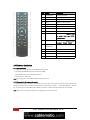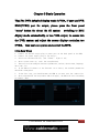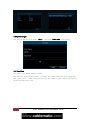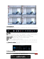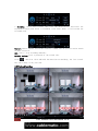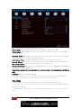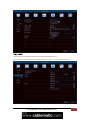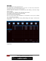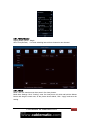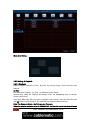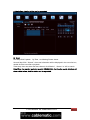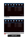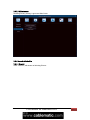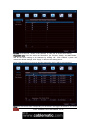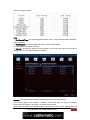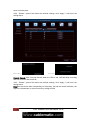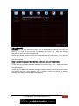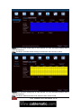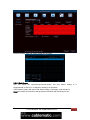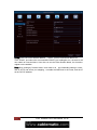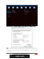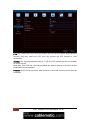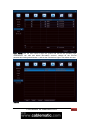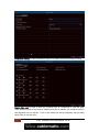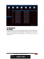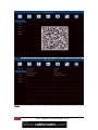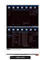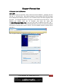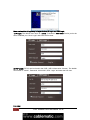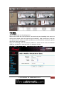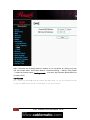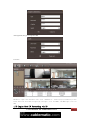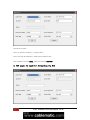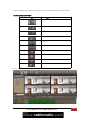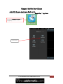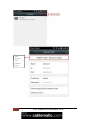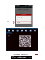
1
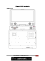
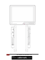
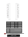
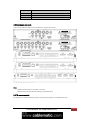
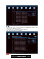
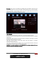
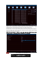
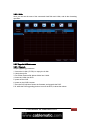
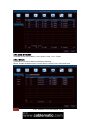
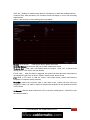
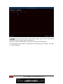
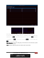
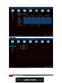
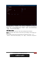
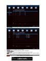
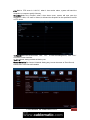
Content . Content......................................................................................................................................................................... 1 Chapter 1 Overview......................................................................................................................................................3 1.1 Introduction.................................................................................................................................................... 3 1.2 Packaging and accessories..............................................................................................................................3 1.3 Main features.................................................................................................................................................. 3 1.4 Technical parameters...................................................................................................................................... 3 Chapter 2 DVR Introduction........................................................................................................................................ 5 2.1 Front panels.................................................................................................................................................... 5 2.2 Rear panel and ports....................................................................................................................................... 6 2.3 IR remote control............................................................................................................................................8 2.4 Hardware installation......................................................................................................................................9 2.4.1 HDD installation..................................................................................................................................9 2.4.2 Connection to the camera and monitor................................................................................................9 Chapter 3 Basic Operation..........................................................................................................................................10 3.1 the Setup Wizard...........................................................................................................................................10 3.2 System Login................................................................................................................................................10 3.3 Live View......................................................................................................................................................11 3.4 Live control bar............................................................................................................................................ 11 3.5 Playback interface........................................................................................................................................ 13 3.6 Main Menu................................................................................................................................................... 13 3.6.1 Basic Setting......................................................................................................................................13 3.6.2 Backup & Playback........................................................................................................................... 18 3.6.3 Upgrade & Maintenance....................................................................................................................23 3.6.4 Record & Schedule............................................................................................................................26 3.6.5 Alarm & Schedule............................................................................................................................. 33 3.6.6 Advanced Setting...............................................................................................................................43 3.6.7 QR & Information............................................................................................................................. 50 Chapter 4 Remote View..............................................................................................................................................54 4.1 Remote view via IE browser........................................................................................................................ 54 4.1.1 LAN................................................................................................................................................... 54 4.1.2 WAN.................................................................................................................................................. 56 4.2 Via CMS....................................................................................................................................................... 57 Chapter 5 Mobile Surveillance................................................................................................................................... 62 Chapter 6 Q & A........................................................................................................................................................68 User Manual for Embedded DVR 1 Notes: The power supply of this DVR is provided through DC12V adapter, please check the power output before installation and ensure it can meet the requirements; Do not place the DVR at a place subject to rain and moisture; Do not install the DVR at a place subject to violent vibration; Do not install the DVR at a place subject to direct sunlight, and be far away from high temperature environment; The DVR should be installed in a space without much dust, and the environment should be kept clean and tidy; The DVR’s back panel should be placed 15cm or more away from other objects or wall for cooling; The DVR should work under temperature, humidity and voltage according to its technical specifications; The space where DVR is installed should not be stored with corrosive chemicals that may produce volatile gases to avoid affecting the DVR’s life; Proper grounding should be guaranteed during operation; The DVR shall be installed to ensure proper connection with other devices. Please buy HDD from official channel to meet DVR’s long time and large data reading and writing requirements. Statement: This manual only introduces basic operation. Products are subject to the real products and this manual is just for reference. Products update without further notice. Nuances of partial functions are permitted before and after updating. Please contact the Customer Service Department for the latest program and supplementary instruction files. This manual is applicable to various models, and the specific operation of each product is not listed here. Users can operate the DVR based on this manual for the actual products. We have tried our best to ensure the completeness and accuracy of this manual. However, due to the unstable environment and other reasons, the real value of some data may differ. If any problem or dispute arises, the company’s final explanation will prevail. If carrying out operation not according to the instruction of this manual, the user shall bear the losses sustained. 2 User Manual for Embedded DVR Chapter 1 Overview 1.1 Introduction This product is a consumer-oriented 4/8/16-channels CIF/Half-D1/D1 real-time network DVR and adopt the industry's most advanced SOC technology and standard H.264 encoding method, so that the image quality is higher, network transmission effect is better and system is more stable; the body is made under stylish appearance design and sophisticated manufacturing process, the 1U standard chassis is suitable for small-scale monitoring places such as shop, supermarket, residential, school, hotel, Internet cafe, family and other civilian sites where require more on video quality, network transmission and real-time playback. 1.2 Packaging and accessories Following parts are included in the package: ◎ One IR remote controller ◎ A pair of remote controller batteries ◎ One piece of product certificate ◎ One piece of product instruction ◎ One piece of SATA hard disk data cable(installed in the host) ◎ One DC12V3A power adapter ◎ Support HDD(already installed) and a set of mounting screws. ◎ One piece of HDD power cable (already installed in the host) ◎ One piece of CD. 1.3 Main features ◎ ◎ ◎ ◎ ◎ ◎ ◎ ◎ ◎ ◎ ◎ ◎ ◎ Standard H.264 video compression format 16-bit true-color semi-transparent graphical menu interface, menu options tip A variety of recording modes: manual, timing, movement and alarm recording Optimized four-channel simultaneous playback (single playback for eight-channel ones) A variety of backup (USB flash drives, mobile hard disk, network) One USB2.0 for data backup, one USB2.0 for the mouse operation Multi-functional operation, recording, playback, monitor, backup and network transmission can be realized at the same time Dual stream technology Support network to implement multi-screen real-time browsing, parameter setting, copy or playback Support mobile phone monitoring Support event classification and precise time search and playback Defaulted parameter value fast recovery Flexible USB interface for mouse 1.4 Technical parameters Features Description Operating system Embedded LINUX OS Video compression H.264 Video input 4/8/16 channels BNC Video output Support BNC, VGA and HDMI Audio input/output Without/1/2/4/8-ch input RCA ;without/1-ch output RCA (optional) Alarm input/output Without/4/8-ch input (optional);without/1-ch output(optional) Display 1/4/9/16-channels User Manual for Embedded DVR 3 Multiplex operation Live, recording, network, ,mobile phone surveillance simultaneously Recording mode Timer/manual/motion detection/alarm Recording frame rate PAL:25fps Recording quality Highest, higher,medium,low,lower,lowest Recording resolution CIF/Half-D1/D1/960H frame rate adjustable Recording playback 1/4/8 /16 channels playback simultaneously(optional) Recording backup Action with Alarm Support USB flash drives backup, moved hard disk backup, network backup, backup by files, backup by time Support Email alarm Send pictures to the designated Email FTP transmission Support PTZ control Support PTZ protocol PELCO-D,PELCO-P etc PIP Support Zoom Support HDD Support 1 SATA HDD,capacity to 4T Network and protocol IE browser 1 RJ-45 10/100M via Ethernet,support TCP/IP、DHCP、DNS、DDNS、 UPNP 、NTP etc Support Client software Support CMS Support Dual stream Support(main and secondary interchange) Group play Support five users online access Multi-language Support Mobile phone surveillance Support windows/symbian/iPhone/blackberry/android operation system QR code Support P2P cloud Support DDNS Support domain name Mouse interface USB2.0 Backup interface USB2.0 Remote controller Support(Support controller ID matching) User authority Support multi-level user authority distribution Power DC12V 3A/5A Working temperature 0℃-50℃ Working humidity 10%-90% 4 NTSC:30fps User Manual for Embedded DVR Chapter 2 DVR Introduction 2.1 Front panels User Manual for Embedded DVR 5 6 User Manual for Embedded DVR User Manual for Embedded DVR 7 Button Name Definition Button Name Definition PWR power indicator LEFT DVR menu to left REC recording indicator RIGHT DVR menu to right LINK network DOWN DVR menu down LCD-POWER LCD power switch UP DVR menu up LCD-AUTO/ESC auto adjust / exit DISP Display mode option LCD-RIGHT/+ Move to right MENU DVR main menu LCD-LEFT/- Move to left ESC DVR menu exit ENTER DVR Menu confirm indicator LCD-MENU/ENTER menu /confirm Physical interface Interface description AUDIO Audio input and output interfaces, please connect according to the digital ID of extension cable 8 VIDEO Video input and output interface NETWORK RJ-45 network interface, connect the Ethernet RS485+/- Connect the RS485 interfaces in equipments like PTZ User Manual for Embedded DVR ALARM+/- Connect alarm switch output DC12V Connect DC12/5A power adapter SENSOR Connect alarm switch input G Alarm input common interface 2.2 Rear panel and ports Note: the real production maybe have some difference with this panels below. Note: 1, RS485 A should connect to PTZ data+, B to data-; 2, Recommend connecting the DVR housing to ground (PE cable). 2.3 IR remote control The DVR can be controlled with the IR remote control. Ensure the batteries are installed before using. User Manual for Embedded DVR 9 NO. Name Description 1 POWER OFF Shutdown the DVR 2 ESC Quit the menu 3 FAST REWIND Change the rewind speed 4 SETP Playback frame by frame 5 PIP Show video picture in picture 6 RECORD Start/stop manual record 7 MUTE Disable the sound 8 NUMBER Switch the channel 9 MENU Enter to the menu(press it 15sec to switch VGA and CVBS operation menu) 10 ENTER Confirm an item (press it 15sec to restore factory default) 11 FAST Change the forward speed FORWARD 12 PLAY / PAUSE Play and pause when playback 13 PTZ Move the PTZ camera 14 SEARCH Playback the video 15 ZOOM Enlarge the channel image 2.4 Hardware installation 2.4.1 HDD installation (1)Open the cover of the DVR, fix the HDD into the bracket;. (2)Connect the HDD data and power cables to the HDD; (3)Tighten the screws to fix the HDD in the case; (4)Lock the cover with crews. Note: Do not plug in or out the HDD when the DVR powered on. 2.4.2 Connection to the camera and monitor Connecting the signal of camera with a BNC cable to the DVR video input, connect the signal of DVR video output with a BNC cable to the monitor (Please refer to the back panel figure). Connect the RS485A (+) and the B (-) respectively to corresponding DVR interface with wires, if camera is the PTZ which can be controlled. Note: Please refer to the electric topology in the last page to connect the devices. 10 User Manual for Embedded DVR Chapter 3 Basic Operation Tips:The DVR defaulted display mode is VGA, if user use DVR BNC(CVBS) port for output, please press the front panel "menu" button for about 15s till system switching to BNC display mode automatically, or use VGA output, to access into the DVR system and adjust the screen display resolution too CVBS, then user can operate and control the DVR. 3.1 the Setup Wizard 1. Connect the DC 12V output plug to power port on the back panel of the DVR; 2. Connect the power supply plug to the outlet; 3. Switch on the Power button, (the “Power” light is on); 4. After system start up, start the setup Wizard; 5. This step you can configure the basic parameters, such as, device name, language, date time ,etc. 6. If the DVR will connect to the Internet via a router, the network parameters should be configured. 7. In the last step, you should format the HDD if you want save the video files. 8. After finished all the steps above and click apply, the DVR will start recording in normal.--End User Manual for Embedded DVR 11 3.2 System Login the factory default user name: admin; password: 0000 0000 (eight Zero) 3.3 Live View The green icon: means normal record. The red icon: means alarm record (“S”means the alarm sensor has been triggered). The yellow icon : means motion detection (red human figures means the motion detection function is on) 12 User Manual for Embedded DVR 3.4 Live control bar Just by one right click the mouse, a control bar will pop up on the screen (as following picture shows): Main menu: click and enter to the Main Menu; Split mode: click and select different display mode; it has 1x1,2x2 display mode etc; PIP: The screen display a main picture, meanwhile, it display a small picture of the others channel at the bottom, (display picture in picture); Sequence patrol: enable multi-camera auto sequence in Live View mode; Digital zoom: enlarge the image in selected single channel; Sound: adjust or disable the audio output; PTZ: control the PTZ dome camera; set the preset direction , cruise line and track, 1. Preset point setting: need to move the PTZ camera in setting the preset point, suggest to set 5 or more direction. 2. Cruise line setting: click “Add”,then you can set the residence time on each preset point. Then the PTZ will start to cruise User Manual for Embedded DVR 13 3. Tracking: Click start record, then click the direction key and select the required rotation path. After it recorded, click Start Track, it will follow the recorded path. Capture: make a channel screen-shot and save to HDD; and the picture can be search in data retrieval. REC: start / stop recording manually; Quickly review: start a playback of the record file. Click , then left click and hold the mouse button and drag, the live control bar can be drag to any position. 3.5 Playback interface 14 User Manual for Embedded DVR 1- Pause:Pause the displaying recording files 2- Stop: Stop the displaying recording files 3- Playback in frame : playback the files in frame after paused. 4- Fast Forward:display the recording files forward at the speed of X1/4, X1/2 , X1,X2,X4,X8,X16, etc. 5- Fast rewind: display the recording files rewind at the speed of X1/4, X1/2 , X1,X2,X4,X8,X16, etc. 6- Single screen : display by one screen 7- multi-screen: display in multi-screen 8- file type: chose the type of recording file, ie. motion detection, sensor alarm, etc. 9- 10 : chose the previous or next files 11-digital zoom: zoom partly in the selected channel. 12-color: adjust the color of selected channel. 13- snapshot: capture the picture of the selected channel or all channels, which can be found in the image search. 14- Edit: edit recording files during playback, which can be gotten after saved. 15- save: save the edited recording files. 16-Audio: close or start the voice while playing back. 3.6 Main Menu Click Menu button and enter, it’s including seven function for the DVR: Basic setting,Backup & Playback, Upgrade & Maintenance, Record & Schedule, Alarm & Schedule, Advanced Setting, and QR & information. 3.6.1 Basic Setting Basic setting is including 6 options: System, Mask. Time, DAT, Live, Main Monitor, and 3.6.1.1 System Click System, as following Picture shows, in this window, user can set up the Device Name, and do Video Format, Password Check, show System Time, Startup Wizard, Max online Users, Screen Resolution, Language, Auto Logout setting etc. User Manual for Embedded DVR 15 The following are the Names and definitions: Device Name: The system name shows in the Client Software or CMS. Video Format : Two kind of Format: Pal and NTSC. User can select it according to the recorder. Password Check: When apply this function, the user need to type in the User name and Password to do system setting operations. show System Time: To select whether display live Time tamp on screen Startup Wizard:Click and it will shows the related information of the Wizard. Max online Users: set up the Max quantity of online user. Screen Resolution: The resolution of the live view. Optional: VGA800*600、VGA1024*768、 VGA1280*1024 and HDMI(1920*1080). Tips:Please connect to relevant Device to control,while switch between the BNC and HDMI Language: Select the Menu language Screen Saver (S): User can set the time interval of the screen saver(30s,60s,180s,300s), If there is no operation ,the system will auto logout and back to login. 3.6.1.2 Time In this window,user can set up and adjust the system Date,System Time,Time zone. The factory default is GMT timezone,Please select the right timezone in the drop-down column(for example:China GMT+8:00). Click"Default",the system will restore default setting;Click"Apply",it will save the setting above. 16 User Manual for Embedded DVR 3.6.1.3 DST In DST window,select DST,Time offset,Mode,from Month/Week/Date/Time etc. Click“Default”,the system will restore default setting;Click“Apply”,it will save the setting above . User Manual for Embedded DVR 17 3.6.1.4 Live Click “Live”and enter the setting window like Picture : Click Channel name, a virtual keyboard will pop up. Click “Shift”, it can switch the input state between Capital letter and Chinese, user can rename the Channel. Click and select the channels in Live interface, then click “Setting”, it will enter “Image Adjust” interface: User can adjust the Brightness, Hue, Saturation,and Contrast; Click “Default” it will restore factory default settings. Click “OK”and save the setting above. User can set the same color parameters to all Channels at once, just by clicking “ALL” ,enter and do the settings. Click “Default”, system will restore factory default setting; click “Apply”, it will save the setting above. Image Adjust: 18 User Manual for Embedded DVR 3.6.1.5 Main Monitor Display Mode options : Single SEQ Time (Second): Live view switching interval from channel to next channel 3.6.1.6 Mask Mask: User can mask at most three area in live view pictures. Mask Area Settings: Click “ Setting”, enter live view picture, left click and hold the Mouse button and drag the mask area, as the picture shows below, Click “ Apply” and save the setting. User Manual for Embedded DVR 19 Mask Area Setting 3.6.2 Backup & Playback 3.6.2.1 Playback System support Playback By Time, By Even, By File,and Image. Click and enter data retrieval. By Time First Step:Click Payback By Time , as following Picture shows: Second Step: select the Channel and display mode, the highlighting date in calendar means it has record. Third Step: Select the date you want to playback, click “Search”, elect the start time and click button to start playback. The selected Time-sheets will shows in blue. Note: The Rows are Hours , the Columns are Channels. When the monitor resolution is set to VGA800*600, the time the search interface will show 20 User Manual for Embedded DVR a hide button, click the button can be expanded. By Event First Step:Click Payback By Time , as following Picture shows: Second Step:Click “ Search”, the event information will be displayed in the event list box, double click the event file to playback. Third Step: User can select the date,channel, click “Motion” , “Sensor” or “All” to search. Note:When the monitor resolution is set to VGA800*600, the time the search interface will show a hide button, click the button can be expanded. User Manual for Embedded DVR 21 By File First Step:Click “ Search”, the event information will be displayed in the file list box. User also can select the date, channel to search. Second Step: Click “All”, user can backup all the selected file. Third Step: Double click the file to playback. 22 User Manual for Embedded DVR By Image: User can do live capture by selecting time and channel, and can do the operation like delete, lock, save to the images. Click the direction key to view the images. The system default image storage is 2000, if over 2000, system will auto cover the old image. Double click the image to playback the record. 3.6.2.2 Backup System support backup the file by USB Device , and remote backup by Internet First Step: Insert the USB storage device, and enter the data backup interface, as picture shows below: Second Step: Select the Start Time and End Time, the Channel, click “Search”, the data information will be displayed in the list box Third Step: Click one data or click “All”to select, then click “Backup”, an Backup Information Window will pop up. Forth Step: In Backup Information window, user can check the file information. Select the Storage Media ,Save file Type, click “Start”to start backup. Note:When the monitor resolution is set to VGA800*600, the backup interface will show a hide button, click the button can be expanded. User Manual for Embedded DVR 23 Select the file and click “Backup”, will pop up a window as picture shows below, User can check the size of selected files and select backup format of the record file, like: H.264 (with Media play, recommended backup format), AVI, WAVE (Audio format). During backup, a backup Progress Meter displays the files being backup and the progress. Due to the frame rate, the AVI format file sometimes has fast forward situation during playback. we will optimize this situation Notice: Pls use computer to format the Removable Hard drive (FAT32 format) before backup the files. The DVR doesn’t support Removable HDD formatting. 24 User Manual for Embedded DVR 3.6.2.3 Disk Here you can see the state of the connected Hard Disk and U disk, and do the formatting operation. 3.6.3 Upgrade & Maintenance 3.6.3.1 Upgrade Simple upgrading procedures: 1. format the U-disk ( FAT32)/ or empty the U-disk 2. Unzip the zip file 3. Put all the firmware file without folder into U-disk. 4. insert the U-disk into DVR 5. power off the DVR 6. power on the DVR & restart 7. then the DVR will Auto Detect the firmware and upgrade the DVR. P.S: while the DVR upgrading pls don't turn off the DVR, it takes few minute. User Manual for Embedded DVR 25 3.6.3.2 Import / Export User can export the Data to USB storage device for backup. and import the Data from USB storage device to DVR. 26 User Manual for Embedded DVR 3.6.3.3 Maintenance Including Factory setting, Logout and Shut Down. 3.6.4 Record & Schedule 3.6.4.1 Record Click “ Record”, will shows as following Picture: User Manual for Embedded DVR 27 Enable: Click “Record”, “Audio” of the Channel, or Click “All” to do the same setting. Record Bit rate: User can select the Resolution, fps, Encode, Quality, and Max Bitrate, and do the same setting to all channels by clicking “All”. Click “Default”, system will restore the default settings; click “Apply”, it will save the setting above. Note: If the fps setting is over than the Max resources, the fps will be auto adjusted. Note:The Record file Size is depending on the bitrate, the bigger the bitrate is, the more 28 User Manual for Embedded DVR memory storage it needs. Time: 1. Pre Record Time: The record length before the event, such as before Motion detection, Alarm event etc. 2. Post Record:The record length after Alarm,Optional time length: 10/15/20/30/60/120/180/300 second; 3. Expired: The effective period of preservation for the record file, When it beyond the setting time, the record file will be auto deleted. Overlay: The Camera Name and the Time Stamp on the Live view pictures. Click Camera Name, Time Stamp, “ Setting”, In live view, user can drag the Camera Name and Time Stamp to any place, as picture shows below: User can do the same Time Stamp setting to all Channel at once, just by clicking “All” and User Manual for Embedded DVR 29 enter to set the place. Click “ Default”, system will restore the default settings; click “Apply”, it will save the setting above. Before drag : After drag : Recycle Record: Click “Recycle Record”,when the HDD is full, DVR will keep recording and auto cover the old record file. Click “ Default”, system will restore the default settings; click “Apply”, it will save the setting above. Note:The Record file Size is depending on the quality, fps,and the record resolution, the higher the Parameters is, the more memory storage it need 30 User Manual for Embedded DVR 3.6.4.2 Schedule Schedule: the row lines means the seven days a week, and the columns means the 24 hours a day, User can set the time by dragging the mouse, the blue area means selected, the gray area means unselected. Select the Channel, double left click the mouse,and edit the weekly plan, as the picture below, Click “Add”to add the record schedule of that day; Click “Delete”to delete the selected schedule. Note: Left click the mouse to drag the time period can quick add the schedule Copy: 1. 1.User can copy the appointed date schedule to the other days. Click “ Apply” and save the setting above. 2.User also can apply one channel’s setting to another channel or all channels, just select the channel and click ”Copy”to apply. Click “ Default”, system will restore the default settings; click “Apply”, it will save the setting above. User Manual for Embedded DVR 31 Motion : it’s the same setting way as Time Record, for more information,please refer to Time record above. Note: The Motion schedule default setting is all selected ,and it shows in yellow. Sensor : it’s the same setting way as Time Record, for more information,please refer to Time record above. Note: The Motion default schedule is all selected ,and it shows in Red. 32 User Manual for Embedded DVR Advance Setting: User can set the actual date and time . 3.6.4.3 Sub-Stream user can adjust the resolution,fps.encode,quality and max bitrate setting to a singlechannel,or click"ALL" to adjust the setting to all channels. Click"Default",system will restore the default setting ,click"Apply",it will set above Note:after select the resolution and fps,system will shows the remaining CIF fps User Manual for Embedded DVR 33 3.6.5 Alarm & Schedule It includes 5 sub-manus Motion, Loss, Sensor, Other , and Output. 3.6.5.1 Motion It includes 2 sub-manus: Motion and Motion Schedule Motion: Enable the Motion Alarm, Set the Alarm Continue Time, Action and Area. 34 User Manual for Embedded DVR Click “All”, ‘”Enable” to enable motion alarm to all channel, or select the needed Channel Continue Time: After the Motion, the continue record time length, it can be set according requirements. Action: Click and pop up the following window as below: Buzzer: Click “Buzzer” , it will buzzer while it detect the motion Show Full Screen: A full screen will pop up while it detect the motion To Alarm Out: Click, and it will enable sense the motion.. Click “OK”, it will save the setting above. Click “Exit”to exit the window. E-mail: Click, when the alarm is triggered, the system will send the alarm information to the specified E-mail, such as Event, capture, device name, device ID etc. FTP: Build a FTP sever in LAN PC, when it has motion alarm, system will send the Snapshot to computer specify Directory Snapshot : Select the Channel, when it has alarm event, system will auto save the snapshot to HDD, if “E-mail” is clicked, it will send the Snapshot to the specified E-mail ID or FTP Sever. To Record: Click the need Channel and “OK” to save the setting above,. Click”Exit” to exit the current interface. User Manual for Embedded DVR 35 To P.T.Z:Set the Alarm Type and No., when there is alarm event, the PTZ Camera will record the event at the alarm point at the first time. Click “OK” to save the setting above, click “Exit” to exit the current interface.. User can apply the same setting parameters to all channels, just by clicking “All”,enter to “Alarm Handling”. , 36 User Manual for Embedded DVR Motion Area Setting: Click “Area”, a window will pop up, as the picture below Set the sensitivity level(1-8), default level is 4, the higher the value is , the greater the sensitivity. Click to select all area as Motion Detection selected Area,; Click Area,; Click to the sensitivity level; Click to delete all to save the settings; Click to exit the current window. Motion Schedule: it’s the same setting way as Time Record, for more information, please refer to Time record above. Note: The Motion default schedule is all selected ,and it shows in Blue. User Manual for Embedded DVR 37 3.6.5.2 Loss Click “Action”, it will pop up the window as below: 38 User Manual for Embedded DVR The trigger setting of “The Alarm” and “To PTZ” in Video lost are the same as in motion detection. User can apply the same parameters of video lost to all Channels by clicking “All” for corresponding setting. “Default” means recover default setting; “Apply” means save above setting. 3.6.5.3 Sensor Alarm Sensor alarm includes 3 sub-menu : Basic, alarm handling, Sensor Schedule. Basic:enable sensor alarm channel, chose alarm type according to alarm trigger type : “NO” or “NC” User can apply the same alarm type parameters to all channels by clicking “ALL”. “Default” means restore factory setting, and “Apply” means saves setup above. User Manual for Embedded DVR 39 Alarm handling : chose the alarm continue time,and lick “Action” Buzzer: when event triggered, Buzzer will work. Show Full Screen: A full screen will pop up while it’s triggered. To Alarm Out: The alarm will be triggered to the appointed alarm output. Email:If alarm triggered, the relevant information, like alarm event, captured pictures, device name, device ID, etc will be send to appointed email box. 40 User Manual for Embedded DVR FTP:Build a FTP sever in LAN PC, when it has motion alarm, system will send the Snapshot to computer specify Directory Snapshot::Select the Channel, when it has alarm event, system will auto save the snapshot to HDD, if “E-mail” is clicked, it will send the Snapshot to the specified E-mail ID or FTP Sever. To Record:Select the Channel and click “OK” to save the setting above,. Click“Exit” to exit the current interface. To P.T.Z:Same setting method as Motion part. Sensor Schedule:The Sensor Schedule Setting way is most the same as Time Record, Please refer to the Record Schedule User Manual for Embedded DVR 41 Note: The Sensor record schedule default setting is all selected ,and it shows in blue. 3.6.5.4 Other The “ Disk Full ” in Alarm type means if the disk capacity is less than the set of Disk Shortage Alarm, relevant prompt will be shown at the bottom right of screen; IP confliction means when 2 or more than 2 PC share the same IP address in the same network segment, alarm will work after setting up the buzzer alarm and trigger alarm; Select “Disconnect”---Click “Buzzer” or “Trigger” , The system will buzzer or send the relevant alarm tips while the internet disconnect. Select “Connection Problem” , user can do Buzzer, E-mail and Alarm Trigger setting. When the HDD is disconnected, the alarm will be triggered. Click “Default”, the system will restore the factory setting,;click “Apply” it will save the setting above. 3.6.5.5 Output Sensor alarm includes 3 sub-menu : Relays, Alarm out Schedule, Buzzer. Relays: In this column, set the “Alarm out name”,and select the Alarm Continue Time (means the time intervals between two alarm action), user can apply the same alarm setting to all the channel by clicking “All”. Click “Default”, the system will restore the factory setting,;click “Apply” it will save the setting above. 42 User Manual for Embedded DVR Alarm out Schedule: Alarm out Schedule Setting way is most the same as Time Record, please refer to the Record Schedule Note: The Alarm Out Schedule default setting is all selected ,and it shows in blue. Buzzer: In this interface, click :”Buzzer”, and select the “Continue Time” User Manual for Embedded DVR 43 Note: The “Buzzer” must be clicked, or otherwise it won’t buzzer. 3.6.6 Advanced Setting It includes 7 sub-manus: Network, E-mail, DDNS, FTP, PTZ, User Admin, and Block / Allow List. Network HTTP Port: Default port: 80, if it is changed, when using IE browser to do remote surveillance, need to add new port after the IP address. For example: if you reset as 7840, you need to type http://192.168.2.133:7804 instead of http://192.168.2.133. Media Port: for CMS,, Mobile App, default setting : 9000 UPNP:Click “UPNP”and enable the function, user can visit the DVR through WAN ( Manual port forwarding is suggested.) Network Type: Including :STATIC, DHCP, PPPOE, and 3G. If select STATIC, it need to set IP address, Subnet Mask, Gateway, preferred DNS Server and Alternate DNS Server. Note: The DVR and the router must in the same network. For example: The Router IP is 192.168.1.1, then the DVR IP must be 192.168.1.xxx, the Gateway is 192.168.1.1. If select DHCP, The device will automatic dispose and set the IP address, Subnet Mask, Gateway, preferred DNS Server and Alternate DNS Server etc. If select PPPoE, user need to enter Broadband or dial-up user name and password, save and restart the system, DVR will will auto obtain an IP address. If select 3G, user need to enter the 3G type (CDMA2000 or WCDMA),save and restart the system, DVR will will auto obtain an IP address. 44 User Manual for Embedded DVR E-mail SMTP Server/ Port: you can find out E-mail SMTP port in the internet Click “SSL Check”, enable to set the E-mail SMTP server (Like Gmail). Send Address/ Password: Sender’s E-mail ID and password. Receive Address: user can enter three different E-mail Address. Click “Test”to verify E-mail. Number of snapshot: Click and enable to send the the snapshot as attached file by E-mail. Snap Time interval: Set the Time Interval between two snapshot. User Manual for Embedded DVR 45 DDNS: User can set the WANIP address , ORAY , 3322 IP and Domain Name etc. Click “DDNS”, and select the recommended DDNS Type: leadingdvr.com, the device will auto obtain an Domain Name, User also can use the other Domain Name, but it need to register on the website . Note:When visiting by Domain Name, User need to do port forwarding setting in router, and do HTTP and server port mapping., or enable the DMZ host in the router, and the IP as the DVR IP address. 46 User Manual for Embedded DVR Note:when you use the DDNS:leadingdvr.com,pls change your PC DNS like this: FTP: this function is similar to the SMTP Server, build a FTP server by LAN computer, set user name and password. Add computer LAN IP address, Port in the DVR, and set the Remote Directory, after setting, then the snapshot can be sent to specify Catalog in computer User Manual for Embedded DVR 47 PTZ: After connect the PTZ to DVR and enable, user can set the Address, Baud Rate and Protocol, only they match the PTZ, then can connect the PTZ Camera to DVR successfully. Address: The supported address range is 1~255, the PTZ address can be set manually on Dome Camera. Baud Rate: Each PTZ has a fixed factory Baud rate, while it connect to the DVR, the two Baud Rate must be consistent. Protocol: Each PTZ has a protocol, while it connect to the DVR, the two protocol must be consistent. 48 User Manual for Embedded DVR User Admin: Use the user name to login the system and has all the operating right, Administrator can add and delete Non-admin account, change all the account passwords,including administrator’s ,and set the Permissions right to non-admin account Add User User Manual for Embedded DVR 49 Permission setting: set the Permissions right to non-admin account according to needs. Block/ Allow List: to block or allow the computer user in a segments to visite the DVR. Click “Block list”,and set the initial IP address and end IP address, the computer users in this segments can not visit the DVR; if click “Allow List”,set the segments, the only allow these users to visit the DVR. 50 User Manual for Embedded DVR 3.6.7 QR & Information 3.6.7.1 QR Code The QR code Image can be scaned by Mobile phone. If the mobile phone didn’t install a surveillance APP, can use other mobile scanning software to scan the QR Code to connect to the download address (Android & Apple ), and download a free Mobile App. If it already install surveillance software (Mobile App), can scan the UID (P2P) to realize mobile live view. User Manual for Embedded DVR 51 System: user can find the Device Name, Device ID, Firmware Version and Release Date. Event: user can search all the events here like: Motion detection, Sensor Alarm,Video loss 52 User Manual for Embedded DVR Log: User can check all users’ device operation (including administrator) Network: user can check the device port, IP Address and P2P (UID) information etc, also can check the Cloud status in this column. User Manual for Embedded DVR 53 Online User: User can check the PC port and APP visitors list in this column. 54 User Manual for Embedded DVR Chapter 4 Remote View 4.1 Remote view via IE browser 4.1.1 LAN When DVR connect to the Router, firstly, check the router IP address,generally, the IP is 192.168.1.1(192.168.1.254), then enter the network control setting of the DVR, and enter the IP Address and Gateway ( Router IP), the IP address must in the same segments with the router. For example: Router IP is 192.168.1.1, the DVR IP set as 192.168.1.X。 After finishing the setting, open the IE Browser, and enter the cloud web site:http://www.easyconfigure.com,or you can enter DVR IP address: http://192. 168. 1. X:Web port, then click “Enter”, and it will download the IE Active-X control ( IE Browser must allow to download the Active-X control, for more detailed operation, please refer to appendix 1) after complete download, a dialogue window will pop up, as the Picture: User Manual for Embedded DVR 55 there are two kind of login way in Login window: IP Login and P2P Login. 1) IP Login: The default User name is “ admin”, Password: “0000 0000”,Device port is the same as Media port. Click “Login” and enter the live view. 2) P2P Login: P2P ID can be found in the DVR ( QR & Information Column), The default User name is “ admin”, Password: “0000 0000”,Click “Login” and enter the live view. Live view : 56 User Manual for Embedded DVR 4.1.2 WAN 1. Via Router Step 1: Please refer to LAN setting above. Step2: After confirm the LAN connection, user need to do port forwarding in the router, as the the picture below. Each DVR need two port forwarding : Web & media port ( user also can add the LAN IP Address to DMZ, and different router has different setting way, please refer to the router user manual). After port forwarding, check the WAN IP Address in “Status” of the router, and add the WEB port via WAN IP to visite the DVR. For example: Visit via http://210.21.229.138:WEB Port or http://Domain Name:WEB Port. User Manual for Embedded DVR 57 Step 3: Because the changing WAN IP Address is not convenient for visiting, user can visit via Domain Name. Enter Main Manuel---Advanced Setting ----DDNS---Click DDNS ----Select the Domain Name :leadingdvr.com。Just enter: http://Domain Name:WEB Port to visit the DVR. 4.2 Via CMS First, please copy the PC CMS from the software disk and install, for the first running,you need to register administrator and set the Password. As the picture below: 58 User Manual for Embedded DVR After registered, then you can login the CMS Live View : Add Device: right click the Device List, click “Add Device”, and will pop up a window as picture below. There are two kinds of Login Type: IP Login ( visit via DDNS), and P2P Login (visit via UID) 1.IP Login: Need IP Forwarding via IP User Manual for Embedded DVR 59 Enter the Device Name, Device IP : Enter the “IP Address” or “Domain Name” ; Device Port: Enter the “Media Port”, and the Factory Default is 9000 Factory Default User Name: admin,and Device Password: 0000 0000 2. P2P Login: No need Port Forwarding via UID 60 User Manual for Embedded DVR After finish adding, right click the new-added device, Click all the Channel and open to remote control The Function Key in Live View: Key Name Live View Remote Playback Local Playback E-Map Config (Screen) Lock PTZ Preset Point Setting Cruise Video (Adjustment) Remote Playback Right click the added device, and click “DVR Setup”, as the picture below. User Manual for Embedded DVR 61 62 User Manual for Embedded DVR Chapter 5 Mobile Surveillance Android for Example, Apple App is Similar to this 1.Please download “VIDEODEFENCEV2” from Google Play or App Store Download”VIDEODEFENCEV2”from Google Play Click “Device” User Manual for Embedded DVR 63 Click “Resgister Type [Common login]” 64 User Manual for Embedded DVR Select “QR Code” User Manual for Embedded DVR 65 Click“Live” 66 User Manual for Embedded DVR Click this User Manual for Embedded DVR 67 68 User Manual for Embedded DVR Chapter 6 Q&A 1. Q: The DVR can not detect HDD A: Please check the HDD cable and the power cable whether is in connection to DVR, or the Main board’s HDD Port whether is in good condition. If yes, please check the HDD whether is the support type to the DVR, please refer to the specification. 2. Q:Forget the password and can’t access into system after chang the password. A: When you forget the login password, please ask technical assistance from technician. A safe ,easily remembered password is recommended. 3. Q: No video signal or abnormal view shows on the Monitor while the DVR and camera in good connection and power supply. A: Please check the BNC connection status, or wether the cable is in aging , or whether the resolution (NTSC/PAL) math or not. 4. Q:The DVR radiating effect A:The DVR will produce heat while it’s running, please put the DVR in a safe and good ventilating place to avoid any bad effect causing by longterm work in high temperature environment . 5. Q:Why the remote control doesn't work while the the remote view and the front panel button is working normally. A:Pls make sure the remote control and the DVR IR receiver must be aligned while operating. If remote control still not working,please check the battery condition. If it's the the problems above, please check whether the remote control is broken or not. 6. Q: Can the DVR support PC HDD if it have been install into DVR? A: The HDD can be used if it is our system support type, but please be noted that all the file will be loss once the DVR runs. 7. Q: Can the DVR keep recording and playback at the same time? A: Yes, it can. Our DVR system support to record and playback at the same time. 8. Q: Can I delete some record file in the DVR HDD? A: For safety, we suggest no to delete some record file, user can format the HDD if he need to delete all the record 9. Q: Why I can not login the DVR CMS? A: Please check the network connection and the setting is correct or not,or whether RJ-45 port is in good connection, or the user name or password for network login is correct or not. 10. Q: Why there is a temporary stutter while remote live viewing. A: It’s normal thing if it stutter within 5 second temporally 11. Q: Can not find any record information while need to playback A: Please check the HDD whether in good connection with the DVR, or the system time is correct or not. If this still happen after setting and restart the system, please check the HDD is damaged or not. 12. Q:After setting, the PTZ can not be controlled. A: Please check the following reasons: 1 ○ PTZ Camera fault User Manual for Embedded DVR 69 2 ○ The PTZ decoder setting, connection,installation are incorrect. 3 ○ The DVR PTZ setting is incorrect. 4 ○ The PTZ decoder don’t match to the DVR protocol ; 5 ○ The PTZ decoder don’t match the device address; 6 While ○ it connect with multi-decoder,you need to add a resistance of 120 ohms at the end of the PTZ decoder line A,B, to eliminate reflection and impedance matching. Otherwise it will cause the PTZ control instability。 13. Q: Why the Motion Detection function is not working A: Please check the Motion Detection setting , level of sensitive are correct or not. 14. Q: Why the Alarm is not working? A: Please check the alarm setting, alarm port, alarm input are correct or not. 15. Q:Why the DVR keep buzzer? A: Please check the whether set as “NC”, relevant Alarm setting, the Motion Detection is enable or not, I/O Alarm and the relevant Disk Alarm setting. 16. Q: After connected to BNC, DVR can display video but the menu, mouse, front panel button and remote control are all unavailable. A: Connect VGA output : change the output to "CVBS" in "main menu-basic setup--system" and then connect BNC output.If no VGA displayer, please press the front panel "menu" button for about 15s till system switching to BNC output mode automatically.. 17. Q: How to do if forgetting password. A: If the modified password is lost , you can press the front panel "menu" button for about 15s to restore the factory default. Factory default password is 0000 0000. 18. Q: If DVR always happens reboot or stops at the turn on logo and can't enter into the system, how to do? A: First of all, take the HDD out and check the problem solved or not. If problem solved, then it should be the HDD's error and formating the HDD is the solution. If problem still exist, please connect seller or supplier for latest upgrading software 19. Q: Connected with VGA or BNC (CVBS definition) output, DVR shows logo but no image displays after entering system. How to do? A: Connect the DVR with HDMI displayer,then alter the definition to VGA or BNC via it. FYI: The suitable definition of BNC is CVBS ; 70 HDMI is 1920*1080 ; VGA are the left options. User Manual for Embedded DVR 未经书面许可,对本产品所附的相关手册之任何内容,不得以任 何方式及任何形式进行复制、传播、 转录或存储在检索系统内, 或翻译成其他语言。 本使用说明书所提到的产品规格及信息仅供参考,内容亦会随时 升级,恕不另行通知。 我司对因未正确使用本产品而引起的损害不承担任何责任。使用说明 User Manual for Embedded DVR 71