1
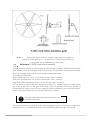
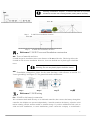
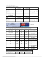
一、Important safety instructions
(must complete a detailed reading, before the assembly use)
1) Read and understand all warnings and take it seriously.
2) Do not install the windy day.
3) If abnormal noise or perceived status, turn off the machine, and with a qualified service personnel.
4) In the assembly and installation process, please take care to tighten all fasteners.
5) Act and in accordance with local electrical standards to determine the grounding techniques.
6) Install the P-300W wind turbine, the state must comply with this manual and warranty
maintenance on the relevant provisions. Failure to comply with the relevant provisions of this
manual and the state may affect your purchase of the product warranty and may cause the warranty.
7) Rotating blade is a high-risk behavior. Install the P-300W wind turbine must ensure that no one
will come into contact with rotating blades.
8) To comply with this manual on "connection" requirement, including the use of recommended
specifications of the wire.
In this manual you will see the following icon:
Warning: do not follow the operation, the device will cause serious damage, personal
injury or even death. Please follow instructions carefully.
Important: critical assembly and operating instructions and recommendations. Not
required to operate, will result in equipment damage.
Tip: streamline operations, facilitate the operation instructions and recommendations.
1
1-1、P-300W Technical Specifications (this machine has rectified 12V, 24V two specifications)
Model
P-300W
Name
Hyacinth
Rated power
300W
Rated DC voltage
DC 12V/24V
Rated current
25A/12.5A
Rated speed
900r/m
Max power
350W
Number of blade
6 pcs
Starting wind speed
2m/s
Cut-in wind speed
3m/s
Cut-out wind speed
15m/s
Security wind speed
40m/s
Rated wind speed
12.5m/s
Engine (generator)
Three-phase permanent magnel generator
Rotor diameter
1140mm
Blade material
Carbon fiber reinforced plastics
Output line anti-winding device
Overall three-phase commutator
Over-speed wind protection
Tip stall protection + turned protection + Electromagnetic
brake
Life span
15 years
Equipment surface protection
Aluminum oxide + plastic coating
2
Refer to the section on the size of paper connecting tower production
Map 1-1
Thrust axis wind speed 45 m * / sec for the 270 * values do not contain beef
safety factor. Our recommended 1.5 safety factor
二、Reference P-300W wind wheel assembly
P-300W at time of delivery has been partially assembled. Further assembly, install the blade to blade
plate, and then leaves the body plate fixed to the generator, and installation of diversion to the blade
drive cap. Assembly need to use the Allen wrench provided with random.
2-1 torque specifications:
Blade to blade plate bolt: 1/4-20 × 1.25 inches, Au stud, cattle • 9.5 meters.
Plate to the rotor blade nuts: 5/8-18 inch, card only nuts, cattle • 70 meters.
Snap locking bolts connecting rod: M5 × 35 mm, Au stud, cattle • 5.5 meters.
See how the leaves onto the leaves on the plate (see Figure 2-1), and then began to assemble. Roots
and leaves in the leaves on the plate coated with a layer of glue that comes with (because of
transportation for security reasons can’t be supplied, at the local hardware store to buy bolt-on glue).
Goal is to not loose all the nuts, cause the fan to damage or accidents.
Nut glue is particularly important to ensure the safe
operation of the future.
The leaves on the leaves on the plate, with a nylon locking nut (Figure 1 4) into the back of the fixed
blade plate groove. A bolt through the blade, screwed into the nylon locking nut - Do not fully
3
tighten the first bolt. Install the second bolt and nylon locking nut and two bolts to 9.5 cattle • m.
According to (Map 2-1) the steps to install the remaining two blades.
If the tilt of the tower to install the P-300W, the next step will be blade / vane plate assembly
mounted to the generator itself. Screw 5/8-18 thread on the shaft nut leaf plate, the leaf disk full
"spin" to the generator shaft. Generator into a body axis in 5 / 16 inch hex wrench, and turning leaves
in the process of the axis of rotation, the blade plate is fully tightened to 70 cattle • m. Map 2-2
If installed on a vertical power tower P-300W, then the first turbine installed in the tower body, and
then install the blade / blade plate assembly, so to avoid the installation of wind turbine blade
rotation - rotating the blade install the P-300W is very dangerous.
Warning: Do not install the blade is rotating wind
turbine
Along the outer edge of the deflector plate vane cap buckle into place. To ensure that all the three
diversion cap buckle into the blade edge is the edge of plate. After installation, pull the deflector cap
to ensure it is securely attached.
Map 2-1
Reference similar(Map2-3)
Map2-2(
(Insert hex wrench, tighten the nut)
三、Reference P-300W
Map2-3(
(promote the diversion cap)
Installation location
Small changes in wind speed may affect the generation of electricity. Thus the wind turbine site
is very important, both considering the tower, the distance to the battery, but also consider local
zoning requirements as well as buildings, trees and other obstacles.
Typically, the higher the tower, wind speed, the higher the final power output.
Minimum recommended tower height is 5 meters (open land), or 5 meters above the surrounding
obstructions (see Figure).Try to install wind turbines in the turbulent few places, because turbulence
will reduce the efficiency of wind turbines, and will accelerate wear on rotating parts.
Select the installation location, the first consideration is safety. Install the P-300W, to ensure that
leaves do not accidentally come into contact with other animals and plants and people (even if forced
to wind turbines installed in the undesirable position).Safety above all else.
4
Warning: Installation "Dolphin", to ensure that there is no possibi
accidental contact with rotating blades (safety above all else).
Map 1
Map 2
P-300W best installation location
P-300W best installation location
四、Reference P-300W Tower and foundation construction
4-1、Tower of materials and sizes
P-300W design for installation in the outer diameter of 51 mm of the tube. This design allows the
P-300W in a lot of tower installation. However, in no case shall the use of plastic pipe to build the
tower.
Warning: Do not use plastic pipe to build the tower!
4-2、Foundation construction, please do the same drawings, with reference to section 5-5
"tower grounding" and Figure 5-5 for ground electrode construction.
Map一
一
Map二
二
Map三
三
Map四
四
五、Reference P-300Wwiring
5-1、P-300W to the battery's connection:
We recommend theP-300W directly to its dedicated controller, then connect the battery through the
controller, the dolphins can operate independently. Controller monitors the battery, adjust the wind
turbine running, and the amount needed to maintain charge. If you have additional needs (such as
wind and solar installations, or street installations, please contact the company to recommend a
5
dedicated controller).
Wind turbine to be connected to the battery by the controller
5-2、Dedicated
controller
P-300W to connect to the battery by the controller
P-300W dedicated controller has the following features:
A, rectifier regulator B, Wind C, charge the battery management (ie, anti-overcharge, over-discharge
prevention)
D, strong wind speed is too high, the P-300W to control speed protection (ie, the brake function)
E, a timer switch on the battery discharge function (light control and time control in two forms)
There are also less comprehensive than commercially available controller does not function, but to
meet the P-300W output voltage and current requirements, but also in line with the battery and the
fan over-speed protection requirements.
P-300W dedicated controller as follows:
5-3、 Dolphin Wind controller instructions
1. Product features and characteristics
1.1: Battery:
1.1.1: Battery over-voltage protection, under voltage protection, reverse polarity protection, short
circuit protection;
1.1.2: System voltage 12V \ 24V Automatic recognition;
1.1.3: Temperature compensation battery charging, and whether the line sensor with automatic
identification function;
1.1.4: Short-circuit protection fuse, fuse built-in but can be replaced;
1.2: Solar panels:
1.2.1: anti-reverse feature and night anti-recoil feature;
1.2.2: unique serial charging circuit, the diode than the average reduction of nearly half of the drop,
effectively improve the efficiency of solar charging;
1.2.3: Pulse modulation charge, charging according to battery voltage automatically adjusts the pulse
width, effectively extending the battery life;
1.3: Wind Turbine:
1.3.1: Manual brake and automatic brake function;
1.3.2: PWM unloading brake design, the fan in unloading the brake, the current is very small, to
avoid the impact of burning high-current motor;
1.3.3: wind turbine brake automatic recovery function;
1.4: Load Output:
1.4.1: Two DC outputs, respectively working without disturbing each other;
1.4.2: multiple operating modes: normally open, pure light control, light control + time control to
open relations;
1.4.3: the unique sensitivity of detection of light control, lighting in the early, middle and late
adjustable;
1.5: LED display:
1.5.1: load output, battery voltage, solar charging, charging wind turbine in the system operation,
6
such as LED display system;
1.5.2: LED indicator function defined
Off 不亮 flash 长亮 bright
负载输出 load output No DC output /
无直流输出
有直流输出
System
operating Under-voltage
蓄电池 Battery
/
系
统运行指示
instructions 欠压
DC output
太阳能 solar panel 不 在
充 Not in charge 充 电
中 charging /
风力发电机 wind generator
不在充电 Not in charge
充电中 charging /
Off 不亮 flash 长
bright
蓄电池 Battery
统运行指示
/
亮
系
负载输出 load output
无直流输出
No DC output /
System
Under-voltage
instructions
operating
DC output
有直流输出
欠压
太阳能 solar panel 不 在
充 Not in charge 充 电
中 charging /
1.6: Definition of the function of dial switch
A(B)路定时时间设置由位 1(4)、位 2(5)、位 3(6)决定
the time setting of load A(B) depends on load 1(4) load 2(5) load 3(6)
A 路定时时间 time
位 Load1
位 Load2
位 load3
说明 discription
(小时)(hour)
(4)
(5)
(6)
纯光控制模式 light
OFF
OFF
OFF
不定时 untimed
control mode
光控+时控 light control
5
ON
OFF
OFF
and time control
同上 light control and
6
OFF
ON
OFF
time control
同上(出厂设置)light
7
ON
ON
OFF
control and time control
同上 light control and
8
OFF
OFF
ON
time control
同上 light control and
9
ON
OFF
ON
time control
同上 light control and
10
OFF
ON
ON
time control
同上 light control and
11
ON
ON
ON
time control
光控灵敏度设置 Light-activated sensitivity Settings
检测电压阀值 detecting
voltage threshold
位 Load 7
位 load 8
说明 description
7
无光控 no time control
2V/12V
3V/12V
4V/12V
4V/24V
6V/24V
8V/24V
OFF
OFF
ON
OFF
ON
OFF
ON
ON
两路长亮 two loads
bright
晚 dusk
中 noon
早 dawn
2.Technical parameters
Wind and solar power system snws400-12V \ 24V
Parameter name Default value range
Control system voltage 12V \ 24V Automatic Identification
Solar panels power rating 150W/12V 300W/24V
Wind turbine rated power of 300W-400W load
Wind turbine brake recovery time of 30 minutes
Match the maximum safety when the battery 200AH
Over-voltage protection voltage 15.0V/12V 30.0V/24V
Float charging voltage 14.4V/12V 28.8V/24V
Charge return voltage 13.5V/12V 27.0V/24V
Over-discharge recovery voltage 12.1V/12V 24.2V/24V
Over-discharge protection voltage 11.0V/12V 22.0V/24V
Battery charge temperature compensation factor 4mV / ℃ / 2V
Temperature compensated battery charging range of -30 ~ 65 ℃
Load type low pressure sodium, lamp, LED lamps, etc.
Single load the maximum output current A Road: 10A B Road 5A
Load normally open output, light control + time control
Light control sensitivity threshold 1 ~ 3V/12V 2 ~ 6V/24V
Load loss ≤ 25mA
Ambient temperature -20 ~ +55 ℃
Storage temperature -30 ~ +65 ℃
Operating humidity range 35 ~ 85% RH (without condensation)
Use altitude ≤ 5500 M
Shell Size 155mm * 147mm * 60mm
Blue aluminum housing material
Natural way of cooling heat
3. Wiring diagram
4. Installation Steps
1,connect battery, turn hand switch to brake.
2,connect wind generator and three phase current input
3,connect
load, the light will be on within 20 seconds
4,connect solar panel. The lights will be off within
8
20 seconds if installed in the day
5 , turn the hand switch back to operating and the
controller will be reset, the brake of wind generator
will be off automatically and finish the installation.
可根据实际配置要求定制增加负载和电池板功率;can increase the power of load and
solar panel according to actual configuration requirements
5.Physical picture
5-4、Wire
selection
2
Please refer to the following choice of conductor wire size metric wire size (mm )
0-9m
12V system
24V system
9-10m
2
6mm
2
10mm
2
2.5m
18-27m
2
4 mm
2
16mm
2
6mm
27-46m
46-58m
2
20mm
2
35mm
2
10 mm
2
16mm
5-5、
、Battery
There are many types of batteries available - maintenance-free lead-acid batteries, gel cell battery
and dedicated wind turbines, the specific type of battery used, depending on the location of the
battery and cost. For the gas discharge is safe and will not cause leakage of battery acid form of
installation, maintenance-free lead-acid battery is a more economical choice.
Minimum recommended battery capacity:
12-volt systems: 200 Ah
24-volt system: 12V 100 Ah, twoλ tandem
Important: Do not wind turbines are not directly
connected to the battery by the controller
5-6、P-300W ground
P-300W grounding, eliminating the possibility of dangerous voltage potential to make people and
equipment are protected.
Ground consists of two aspects - one of the electrical system grounding conductor and the conductor
may be due to electrical failure with a voltage potential of the grounding of all metal structure.
(Please refer to the instructions of the supplier of electrical grounding)
9
Strongly recommended that installation of the vessel grounded. For vessels, especially vessels
connecting DC power ashore, grounding must comply with special requirements, may cause serious
electric shock hazard.
5-7、Tower grounding
Each wind turbine and tower must be grounded in the base of the tower, even though the system may
have been at the service panel or battery ground wire through the yaw were grounded. Ground at the
tower at the base of the tower to prevent failure due to electrical contact with the tower of causing
electric shock.
The following content is for reference only. Recommend that you review the provisions of state on
the ground.
Tower grounding in several ways. The most common way is to laminate steel electrodes into the
ground, and use wire to connect it to tower.
Schematic ground electrode 5-5
六、Reference P-300W system installed
Before installation, be sure to complete the following basic steps:
● comprehensive reading P-300W user manual
● tower and site selection, installation of tower.
● determine the wire size (see Section 5.4 of this manual).
● system design, including battery, controller and inverter, to draw the line graph.
● obtain the required components.
● Wind wheel assembly (see the second part of this manual, "the wind wheel assembly").
Once completed, the final installation is quite simple. Including the electrical connections according
to wiring diagram and the P-300W onto the top
of the tower.
6-1、For the P-300W to wires
Warning: Prior to the completion of all electrical
connections, do not wire to the battery.
Entangled with each other using welding or wire connection, the P-300W three wires are connected
to outlet pipe along the tower down, follow work rules, the use of high-quality electrical insulation
adhesive tape on the connection part. Leave enough wire for the maintenance of leeway, so that the
P-300W from the top of the tower removed.
Accordance with the system circuit diagram, the wires to the controller, the controller switches on
10
the hand brake to the brake position, until all connections.
6-2、The P-300W installed in the tower top
In the Connect the wires to the P-300W, the tower down to the wire along, and P-300W connection
locking slide tower lock. Full tower set into the connection lock after the top of tower, and then
connect locking to bring about 3 to 6 mm between the lock and the top of the tower across the rubber
insulation pad, so the tower can reduce the noise and vibration.
Connection lock installed, use the supplied 5 / 32 inch hex wrench to lock assembly tighten the
clamping bolt - tighten to 7 Nm. (Map 6-1)
If the blade / vane disc set has not been installed in the generator body, you can now be installed.
The 5/8-18 nut leaf plate into the groove of the central hexagonal fixed. Be screwed to the plate and
leaves the generator shaft. Insert a generator shaft 5 / 16 inch hex wrench, keeping the fixed blade,
tighten the wrench, torque to 70 Nm. (Map 6-2)
Along the outer edge of the blade plate, the deflector cap snaps into place. To ensure that diversion
cap in all three edges are the outer edge of the buckle into the blade plate. After installation, pull the
deflector cap to ensure it is securely installed. (Map 6-3)
11
ERROR: ioerror
OFFENDING COMMAND: image
STACK: