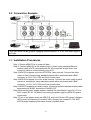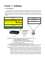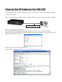
1
IVS-255
Real-time MPEG4 Industrial Video Server
User Manual
(Version: 1.0.0)
IVS-255 User Manual, Rev. 1.0.0: Mar 20, 2006
The information in this document is subject to change without prior notice in order to
improve reliability, design and function and does not represent a commitment on the part of
the manufacturer.
In no event will the manufacturer be liable for direct, indirect, special, incidental, or
consequential damages arising out of the use or inability to use the product or
documentation, even if advised of the possibility of such damages.
This document contains proprietary information protected by copyright. All rights are
reserved. No part of this manual may be reproduced by any mechanical, electronic, or other
means in any form without prior written permission of the manufacturer.
Revision
Date
1.0.0
2006/03/20
Description
First release
2
Contents
Chapter 1 : General Introduction .........................................5
1.1 Product Features..................................................................................................... 5
1.2 Product Pictures ..................................................................................................... 7
1.3 Specifications ......................................................................................................... 8
1.4 Mechanical Dimemsion ......................................................................................... 8
Chapter 2 : Hardware Installation ........................................9
2.1 Front and Rear Panel Overview............................................................................. 9
2.2 Connection Example ............................................................................................ 10
2.3 Installation Procedures......................................................................................... 10
Chapter 3 : Software............................................................11
3.1 Architecture.......................................................................................................... 11
3.2 UDP Packet Format ............................................................................................. 12
Server Port: 8000 – To receive MP3 Frame Data from (a) client............................................................ 12
Server Port: 8001 – To receive linking request from a client .................................................................. 14
Server Port: 8002 – To receive operating request from a Client............................................................. 16
Receiving MP4 Video and ADPCM Audio Stream from IVS-255............................................................ 19
3.3 Sending data to RS232......................................................................................... 21
3.4 Receiving data from RS232 ................................................................................. 21
Chapter 4 : ActiveX Controls..............................................22
4.1 ViewerCtrl............................................................................................................ 22
4.2 MP3EncoderCtrl .................................................................................................. 22
4.3 VSLinkCtrl........................................................................................................... 23
How to Set IP Address for IVS-255 ....................................25
3
What you received
After receiving the package of IVS-255, please unpack it and check if the following items
are included.
IVS-255, Real-time MPEG4 Industrial Video Server
Software CD
DC 12V power adaptor
Audio output Cable
** The software CD includes client site SDK and manuals.
** The DC 12V power adaptor accepts power input from AC 100~ 220 V, 50 ~60HZ.
Client-Server Definition
IVS-255 follows client-server structure. Throughout this manual the terms ‘client’ and
‘server’ will refer to client PC and IVS-255 respectively.
IVS-255
Ethernet
Server Side:
Hardware IVS-255
CPU: Xscale
OS: Embedded Linux
Client
Client Side:
Hardware: PC
OS: Windows 2000/XP
4
Chapter 1 : General Introduction
The IVS-255 is a high performance standalone video server, based on Intel xScale
pxa-255 CPU, 400Mhz, and embedded Linux OS. It could simultaneously perform 4Ch
real-time MPEG4 video encoding, 4 CH ADPCM Audio encoding, 1 CH Audio play-out, and,
then transmit Audio/Video stream data out through Ethernet. The rugged hardware design,
low power consumption, and fan-less features make this product especially suitable for
industrial field application.
1.1 Product Features
-
CPU: Intel xScale PXA-255 CPU @ 400 MHz
OS: Embedded Linux 2.4.19
Low power consumption, no fan inside
Hardware watch dog protection mechanism
Support 4-CH MPEG4 video and 4-CH audio real-time encoding
Support 1-CH real-time audio out
ActiveX Control SDK for AP developing
Ready for integration with InduSoft Web Studio
Support 4 Channel MPEG4 Video Encoding
IVS-255 receives video signals from standard NTSC or PAL
CCD camera, and, encodes them into MPEG4 stream. The
encoding is performed by dedicate ASIC, so, it is real-time. When
using CIF (320*240 or 352*288) mode, IVS-255 could support up
to 4 cameras, and, produce 4 independent streams. If one of the 4
channels needs full VGA or D1 solution, the other 3 will be turn-off.
The switching between 4 CIF and 1 D1 is on the fly. That means
user could make switching without reboot IVS-255.
5
Support Bi-directional Audio
IVS-255 provides bi-directional audio function. For audio
input, it receives up to 4 analog audio input signals, and,
encodes them into ADPCM streams. The 4 channels devote to
4 video input channels individually. So, if some video channel is
disabled, the corresponding audio also becomes inactive.
For audio output function, IVS-255 receives the MP3-like
stream from remote client via Ethernet. Then, it decodes and
renders it. The audio stream from client is generated by client
ocx provided by IVS-255 SDK. IVS-255 supports one channel audio output.
Streaming on Ethernet
IVS-255 generates video and audio stream and transmits
Ethernet
Client
them to client via Ethernet with UDP protocol. The using of
UDP has some reasons. First UDP is faster then TCP, thus,
has better real-time performance than TCP. Second, UDP
consume lower CPU resource then TCP.
To delivery multimedia streaming on Ethernet is a
complicated effort. It needs to take care a lot of jobs such as
buffering, packaging and un-packaging, frame losing
detection … etc. Fortunately, IVS-255 and its client side SDK
software already did these jobs.
PTZ Control
For those who want to use PTZ camera, IVS-255 provides a
RS-232 port to sending PTZ commands. Since, the PTZ protocol
is different from one maker to the other. IVS-255 didn’t define any
PTZ command inside but providing a set of RS-232 send/receive
software functions. These functions are part of software SDK
ocxs.
6
Hardware Watch Dog
Design on PXA-255, IVS-255 makes use of hardware WDT
function of its CPU. The working theory is that client must
periodically send WDT signal to IVS-255. If not, the IVS-255 will
reboot itself and restore to initial statue to waiting connection
from client. This mechanism can protect IVS-255 from
mal-function due to communication error or any other
un-expected conditions.
Embedded Linux
The software inside IVS-255 is based on embedded Linux.
The kernel version is 2.4.19 and root file system is jffs2. For
advanced user, who knows Linux very well, can design his own
AP inside.
1.2 Product Pictures
IVS-255: Front View
IVS-255: Rear View
7
1.3 Specifications
Intel® xScale® PXA-255 @ 400 MHz400 MHz Memory
SDRAM: 32 MB, Flash: 16 MB
Require power input: 12 V DC
Number of (Channels): 1
Power
Ethernet
Bit Rate: 10/100 Mbps
Power Consumption: 5W
Number of Channels: 4
Input video type: NTSC / PAL
Video
Encode Compression type: MPEG4 ISO/IEC 14496-2, SOP @LEVEL3
Performance: NTSC 320x240 @ 120fps, PAL 352x288@100fps
Number of (Channels): 1
Number of Channels: 4
Audio
Audio
Audio stream format: MP3 streaming
Sample Rate: 8 KHz, Mono
play-out
Encode
Sample Rate: 44.1 KHz, Mono
Audio compression type: ADPCM
Number of Channels: 1
RS232
Connector: DB9 male
-15 ℃ ~(+) 65 ℃
Operation temperature
-40 ℃ ~(+) 85 ℃
Storage temperature
CPU
EMI,CE / FCC / VCCI
Certification
1.4 Mechanical Dimemsion
8
Chapter 2 : Hardware Installation
2.1 Front and Rear Panel Overview
9
2.2 Connection Example
Note: The camera in this graph is equipped with microphone, so, it can send audio signal to
IVS-255.
2.3 Installation Procedures
Step 1: Ensure AEM ICS is in power-off state.
Step 2: Connect AEM ICS to the network hub or switch using standard Ethernet
network cable (CAT5) terminated with RJ-45 connectors at both ends. Use
crossover cable to connect directly from a PC.
Step 3:AEM ICS supports up to four NTSC/PAL video sources. Connect the video
output of each camera using standard coaxial cable, terminated with a BNC
connector, to CH1, CH2, CH3 and CH4 of video input.
Step 4:AEM ICS supports up to four audio sources. Connect the audio output of each
camera or microphone using standard coaxial cable, terminated with a BNC
connector, to CH1, CH2, CH3 and CH4 of audio input.
Step 5:AEM ICS supports one audio output. Connect a speaker standard coaxial cable,
terminated with a BNC connector to AUDIO OUT.
Step 6:Ensure the power supply adapter matches the specification (input AC 110V or
220V, output DC 9V 1A) before connecting the power supply to AEM ICS power
cord socket.
Step 7:Turn on the power switch on AEM ICS, check the Power LED (green), Network
LED (green) and Network Connection LED (orange) are constant lit. The WDT
LED (orange) displaying link status should constantly blink.
10
Chapter 3 : Software
3.1 Architecture
In most cases, the IVS-255 serves as a server, which provides the service of converting
analog Video and Audio signals into MPEG4 and ADPCM stream data and sending it to
clients via Ethernet. To achieve this, the IVS-255 implement not only hardware, but also
layers of software. This section is devoted to an introduction to the software layers of the
IVS-255.
Server AP
Client AP
File System
ActiveX Controls
Driver
Windows
Embedded Linux OS Kernel
Bootloader
IVS-255 Hardware
UDP socket protocols
IVS-255
Ethernet
Client
Bootloader: this layer of software is closest to the hardware. It helps to:
1.
2.
3.
4.
Setup SDRAM and PXA255 registers
Activate and configure all ICs on IVS-255
Load (the) OS kernel and File system into SDRAM
Pass execution to (the) OS
Please refer to the bootloader section for further information.
Embedded Linux OS kernel, Driver and File system: IVS-255 uses a 2.4.19 Linux
kernel. Please refer to the embedded Linux section for further information.
Server AP: The IVS-255 is equipped with a server AP. This AP realizes the socket
protocols defined in later sections so that the user can design his client AP
based on these protocols. Please refer to the UDP Packet Format section for
detailed information. The source code of the server AP is also provided for
advanced users to develop their own AP. In this case, the IVS-255’s originally
defined socket protocols become invalid, and the user may define his own
protocol. Of course, the ActiveX controls provide together with IVS-255 is
11
useless if use define a different socket protocol.
UDP socket protocols: Define the communication between client and server using
the UDP socket
ActiveX Controls: Three Windows ActiveX controls are available for the user to
develop his client AP. These 3 controls implement socket protocols defined in
the UDP Packet Format section. Because it is the server AP that implement
these protocols, the IVS-255 must run the original server AP provided with the
IVS-255.
3.2 UDP Packet Format
This section describes packet contents used for communication between client PC and
the IVS-255.
- The communication between client and server uses UDP sockets.
- Every IVS-255 has a unique IP address and the client must know its IP in order to
allocate the IVS-255
- Communications with different purposes use different socket port:
Client needs at least 3 ports:
1st port, used to send UDP packet to server port 8000 ~ 8002
2nd port(AV_LocalPort), used to receive MP4 video and ADPCM audio stream
data from server
3rd port(LocapPort), used to receive other response data from server
Server uses 5 ports:
Port 8000: used to receive MP3 stream data from client that is linked to it
Port 8001: used to receive a linking request from any client
Port 8002: used to receive all other requests from client that is linked to it
Port 8003: used to send MP4 video and ADPCM audio stream data to client
that is linked to it
Port 8004: used to send response data to a client
Server Port: 8000 – To receive MP3 Frame Data from (a) client
The IVS-255 uses socket port 8000 to receive MP3 frames from a client. The packet
data contents are described as following:
MP3 frame
Frame_SerialNumber
Frame_Header
2 bytes
4 bytes
Frame_Data
Frame_SerialNumber: 2 byte, 0x0000 ~ 0xFFFF
12
- Every next frame increases the SerialNumber by 1.
- After ‘0xFFFF’, the next frame takes 0x0000 as its serial number.
Frame_Header: 32 bit.
- Frame_Header contains standard MP3 Frame Header.
- Each frame has its own header
Frame_Data:
- These are compressed MP3 audio data
- 418 or 417 bytes
Programmers are responsible for the following issues:
Every 26 ms, a new frame packet arrives at the server
The client must link to the server before it starts to send MP3 frame packet.
Unexpected problems may occur if a client sends a frame packet to a server that is
linked by another client.
13
Server Port: 8001 – To receive linking request from a client
Linking request is sent to the IVS-255 at port 8001. Any client can send a linking
request packet to the server, whether the server is linked or not, and the server must
reply to the client at the client’s port. So, the client can also use this port to test whether a
server exists and/or if a server is free to link.
The linking request packet format (client to server)
Number of Bytes
4
2
Client IP
-
LocalPort
2
AV_LocalPort
1
1
CH_Enable
VideoMode
1
FrameRate
1
Quantization
IP_Interval
ClientIP: Client IP address.
LocalPort: Client local port number, to tell server which client port to send all
UDP packets, except AV stream data.
AV_LocalPort: Client AV local port number, to tell server which client port to
send AV stream data.
If AV_LocalPort = 0, server will treat this request as linking status
checking only, no actual linking action processed.
If AV_LocalPort is not 0, server will process the linking request.
-
CH_Enable: bit operation, 0: for disable, 1: for Enable (1 Byte)
bit 0: Video Channel 0 Enable/Disable
bit 1: Video Channel 1 Enable/Disable
bit 2: Video Channel 2 Enable/Disable
bit 3: Video Channel 3 Enable/Disable
bit 4: Audio Channel 0 Enable/Disable
bit 5: Audio Channel 1 Enable/Disable
bit 6: Audio Channel 2 Enable/Disable
bit 7: Audio Channel 3 Enable/Disable
-
VideoMode: (1 Byte)
0: NTSC Cif, 320 * 240
1: NTSC Full, 640 * 480
2: PAL CCIF, 352 * 288
3: PAL Full, 702 * 576
-
1
Note: The VideoMode byte does more than video mode setting. It
also carries Motion detection sensitivity information.
Bit 0,1: Video Mode
Bit 2~7: MD sensitivity value
Value:
(000000XX):
sensitive
FrameRate: Video
frame0 rate
setting (1extremely
Byte)
Value:
default MD sensitivity
0: 30 (NTSC)
, 25 40(101000XX):
(PAL) frame/sec
Value: 63 (111111XX): no MD
14
-
1: 15 (NTSC) , 12.5 (PAL) frame/sec
2: 7.5 (NTSC) , 6.25 (PAL) frame/sec
3: 3.75 (NTSC) , 3.125 (PAL) frame/sec
4: 1.875 (NTSC) , 1.5625 (PAL) frame/sec
5: 0.9375 (NTSC) , 0.78125 (PAL) frame/sec
Quantization: Quant. value 1 ~ 31 (1 Byte)
IP_Interval: (1 Byte)
0: IP interval = 2
1: IP interval = 4
2: IP interval = 8
3: IP interval = 16
4: IP interval = 32
5: IP interval = 64
6: IP interval = 128
7: IP interval = 256
Response packet format for linking request (server to client)
This response packet is received by a client at LocalPort defined in previous linking
request. The packet format is:
ServerIP
-
LinkResult
4 bytes
1 bytes
ServerIP: The server IP address (4 Byte)
LinkResult: (1 Byte)
0x00: Client Link successfully(AV_LocalPort is not 0), or client is
free for link(AV_LocalPort= 0)
0xFF: AlreadyLinkedByCurrentClient
0xFE: AlreadyLinkedByOtherClient
0xFD: Error_WrongVideoMode (AV_LocalPort is not 0)
0xFC: Error_WrongFrameRate (AV_LocalPort is not 0)
0xFB: Error_WrongQuantization (AV_LocalPort is not 0)
0xFA: Error_WrongVideoIPInterval (AV_LocalPort is not 0)
15
Server Port: 8002 – To receive operating request from a Client
The server receives all operation requests at this port. Only after server is linked, this
port became active, otherwise, no action is taken nor data responded to. The server
replies to the client at client LocalPort specified in previous linking request.
Request format (client to server)
Request_ID
Data
1 bytes
Request_ID
1
2
3
4
5
Requested Function
Checking current configuration
Watch Dog Clear
Configuration change request
Server reset request
Unlink request
Data Size
0 byte
0 byte
5 bytes
0 byte
0 byte
Checking current configuration:
- To check the current configuration, send a request with ID = 1. The server
replies with the current configurations to the client.
- Data content: Empty
Watch Dog Clear
When a server receives a Watch Dog Clear request, it replies to the client.
Once a server is linked by a particular client, the client must keep sending this
request port every second.
If a server doesn’t receive any packet at this port after more than 5 seconds, a
hardware reset occurs using WDT.
Data content: Empty
Configuration change request
- When a server receives a Configuration change request, it replies to (the)
client.
- Data:
CH_Enable
-
VideoMode
FrameRate
Quantization
IP_Interval
1 bytes
1 bytes
1 bytes
1 bytes
CH_Enable: For the channel enable/disable setting, refer to previous sections
for value definition
VideoMode: For the video mode setting, refer to previous sections for value
definition
1 bytes
16
FrameRate: For the video frame rate setting, refer to previous sections for value
definition
- Quantization: Quant. value 1 ~ 31 (1 Byte)
- IP_Interval: For the video IP interval setting, refer to previous sections for value
definition
Server reset request
When a server receives a Server reset request, it resets itself immediately
without a reply.
Data content: Empty
Unlink request
When a server receives a unlink request, it will stop sending stream and return
to free state, that could allow other client to link on it. The server will not send a
reply to originally linked client.
Data content: Empty
-
The response packet format (server to client)
ServerIP
Request_ID
Data
4 bytes
1 bytes
ServerIP: The server IP address (4 Byte)
Request_ID:
Request_ID Requested Function
1
Replying current configuration
2
Replying Watch Dog Clear
3
Result of Configuration change request
Data Size
5 bytes
0 bytes
1 bytes
Replying current configuration
- When the server receives a current configuration checking request, it replies
to the client
- Data Contents:
CH_Enable
-
FrameMode
FrameRate
Quantization
IP_Interval
1 bytes
1 bytes
1 bytes
1 bytes
1 bytes
CH_Enable: For channel enable/disable setting, refer to previous sections for
value definition
FrameMode: For the video mode setting, refer to previous sections for value
definition
FrameRate: For the video frame rate setting, refer to previous sections for value
definition
Quantization: Quant. value 1 ~ 31 (1 Byte)
IP_Interval: For the video IP interval setting, Please refer to previous sections for
value definition
17
Watch Dog Clear Replay
- When a server receives a Watch Dog Clear request, it replies to the client
- Data Contents: Empty
Result of Configuration Change Request
When a server receives a Configuration Change Request, it replies to the
client
Packet Content:
Result
-
1 bytes
Result: (1 Byte)
0x00: Configuration Changed successfully
0xFE: AlreadyLinkedByOtherClient
0xFD: Error_WrongVideoMode (AV_LocalPort is not 0)
0xFC: Error_WrongFrameRate (AV_LocalPort is not 0)
0xFB: Error_WrongQuantization (AV_LocalPort is not 0)
0xFA: Error_WrongVideoIPInterval (AV_LocalPort is not 0)
18
Receiving MP4 Video and ADPCM Audio Stream from IVS-255
The server sends out an MP4 Video and ADPCM Audio data stream to the client’s
AV_LocalPort, which is told to server in the linking request. The pocket data contents
are described as following:
MajorType
MinorType
Length
Data
1 bytes
1 bytes
2 bytes
MajorType: 1 byte
- Indicates the major type of packet data
- There are two major types:
SP_MEDIA (0xA0), packet data is header information
SP_DATA (0xD0), packet data is stream data
- When SP_MEDIA major type is received, PutHeader() method in ViewerCtrl
should be called to place header information.
- When SP_ DATA major type is received, PutData() method in ViewerCtrl
should be called to place stream data.
MinorType: 1 byte
- Indicates the following packet data is Video or Audio
- For SP_MEDIA major type, the MinorType defines that:
MinorType = MEDIA_VIDEO (0x01), packet data is Video header
information
MinorType = MEDIA_AUDIO (0x02), packet data is Audio header
information
- For SP_Data major type, the MinorType defines that:
MinorType = MEDIA_VIDEO (0x01), packet data is Mp4 Video frame
data
MinorType = MEDIA_AUDIO (0x02), packet data is ADPCM Audio
frame data
Length: 2 byte
- Identifies the length of Data, not including MajorType, MinorType and
Length itself.
- In byte unit.
Data:
- The Data contains header or stream data of compressed Mp4 Video or
ADPCM Audio
- Refer to the following table for data contents
19
MajorType MinorType
Data
Byte 0 in Data: FrameWidth (2 byte)
MEDIA_VIDEO Byte 2 in Data: FrameHeight (2 byte)
Byte 4 in Data: 30 / FramePerSecond (1 byte)
SP_MEDIA
Byte 0~3 in Data: SampleRate (4 Byte)
MEDIA_AUDIO Byte 4~7 in Data: BitRate (4 Byte)
Byte 8 in Data: ChannelMode (1 byte), always = 2, for ADPCM
Byte 0 in Data: Current Frame Number (1 byte)
Byte 1 in Data: Current packet count for current frame number
(1 byte)
Byte 2 in Data: Total packet count for current frame number (1
byte)
Bit 4~7 of Byte 3 in Data: Channel Number (4 bits)
Bit 0~3 of Byte 3 in Data: Video Key Frame (4 bits)
MEDIA_VIDEO Note: the “Video Key Frame” tells more than Key frame
information. It also carries Motion detection information.
Bit 0,1 of byte 3 in data: Video Key Frame
Bit 2,7: MD information
SP_DATA
Value: 0 (XXXX00XX): No Motion detected
Value: 1(XXXX01XX): Motion detected
Byte 4 ~: Compressed Mp4 Video data ((Length – 4) byte)
Byte 0 in Data: Current Frame Number (4 byte)
Byte 1 in Data: Current packet count for current frame number
(1 byte)
Byte 2 in Data: Total packet count for current frame number (1
MEDIA_AUDIO
byte)
Bit 4~7 of Byte 3 in Data: Channel Number (4 bits)
Bit 0~3 of Byte 3 in Data: Reserved
Byte 4 ~: Compressed ADPCM Audio data ((Length – 4) byte)
20
3.3 Sending data to RS232
This section describes a function that allows client user to output data to IVS-255’s RS232,
COM2 port. The default setting of COM2 is 9600, n,8,1.
Client
IVS-255
PTZ Camera
TCP port:
8100
Data
Data
RS-232
Ethernet
1st, the Client user sends string data to IVS-255’s Ethernet, at port 8100, TCP
2nd, the VS_server get the string data from Ethernet.
3rd, VS_server outlet this string data to RS232 port, the COM2.
3.4 Receiving data from RS232
This section describes a function that allows client user to get string data that input to
IVS-255’s RS232, COM2 port. The default setting of COM2 is 9600, n,8,1.
Client
IVS-255
TCP port:
8100
String Data
String Data
Ethernet
RS-232
1st, the VS_server read RS232, COM2, every 100ms, to check if string data input
2nd, the VS_server get the string data from RS232, COM2.
3rd, the VS_server sends string data to Client via port 8100, TCP. Note, Only the
Client who linked to IVS-255 can get this string data.
For further information, Please refer to:
IVS-255 Client Site ActiveX Control Programming Guide
21
Chapter 4 : ActiveX Controls
The IVS-255 is shipped with three ActiveX Controls to support user’s AP development on
the client site. They are ViewerCtrl, MP3EncoderCtrl and VSLinkCtrl
ViewerCtrl: Used to play AV streams from IVS-255.
MP3EncoderCtrl: Used to compress Audio input into MP3 frames.
VSLinkCtrl: Supports linking to IVS-255
4.1 ViewerCtrl
This ActiveX control is used to play compressed AV stream data on the client side.
Being an ActiveX control, it supports the following properties and methods.
Property
Method
SavedFileName [*.avi]
EnableAudioPlay
Open (*Source)
Close()
PutHeader(bVideo, *Data, Size)
PutData(bVideo, VSerNumber, Key, *Data, Size)
4.2 MP3EncoderCtrl
This ActiveX control is used to encode audio input into MP3 frames. The sample rate is
44.1kHz, bit rate is 128 Kbps and mono-channel. It also enumerates all possible audio input
sources for the user’s selection. Being an ActiveX control, it supports the following property,
methods and event.
Property
AudioInputSource
Method
Event
Mp3EncodeStart()
Mp3EncodeStop()
StreamReady(*Data,Size)
22
4.3 VSLinkCtrl
This ActiveX control is used to
Define Server IP addresses and the client local ports (LocalPort and AV_LocalPort)
for receiving UDP sockets from the server
Send encoded Mp3 frame data to the IVS-255.
Receive MP4 Video stream and ADPCM Audio stream data from the IVS-255
Monitor the status of the IVS-255
Control and Configure the IVS-255
Reset the IVS-255
Send data to RS232, COM2
Receiving data that input to RS232, COM2 of IVS-255.
Being an ActiveX control, it supports the following properties, methods and events
Properties IP_Address
LocalPort
AV_LocalPort
ServerReady
Video_Mode
Video_0_Enable,
Video_1_Enable,
Video_2_Enable,
Video_3_Enable
Audio_0_Enable,
Audio_1_Enable,
Audio_2_Enable,
Audio_3_Enable
VideoFrameRate
VideoQuantization
VideoIPInterval
BitRate
RS232DataType
MDSense
Methods VS_Link()
VS_unLink()
SendMP3Stream(*Data,Size)
ConfigurationChange()
ResetServer()
SetRS232SendBuffer(Index, Data)
SendRS232(Length)
ReadRS232Data()
HeadStreamReady(Channel, bVideo, *Data, Size)
Events
DataStreamReady(Channel, bVideo, VSerNumber, Key, *Data,
Size)
23
ServerDown()
FrameDrop(Channel)
ReceiveRS232String(Data, Size)
ReceiveRS232Binary(Length)
MotionDetected(Channel)
24
How to Set IP Address for IVS-255
The IP address of IVS-255 has its factory setting as “192.168.0.218”. To set a new IP, please follow
the instructions below:
Step 1: Connect a crossover RS232 cable to COM1 of IVS-255 and the other side to a PC’s COM port.
Crossover RS232 Cable
Step 2: Execute HyperTerminal on PC.
Step 3: Under HyperTerminal, the COM port setting is “115200, 8, n ,1” “No flow control”
Step 4: Press Connection button on HyperTerminal, and then press [Enter] key for several times. The
HyperTerminal shall look like this.
Step 5: Login: “root”, then press [Enter] key.
Step 6: Use the command “IPSetup” to set up new IP address for IVS-255
25