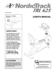
1
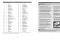
HOW TO ORDER REPLACEMENT PARTS
If you encounter any difficulties with this product, or if you need to order replacement parts, call the ICON Health
& Fitness, Ltd. office, or write:
ICON Health & Fitness, Ltd.
Unit 4, Revie Road Industrial Estate
Revie Road
Beeston
Leeds, LS118JG
UK
Model No. NTEVEL08990
Serial No.
USER’S MANUAL
Serial
Number
Decal
Tel:
08457 089 009
Outside the UK: 0 (044) 113 387 7133
Fax: 0 (044) 113 387 7125
When ordering parts, please be prepared to give the following information:
• The MODEL NUMBER of the product (NTEVEL08990)
QUESTIONS?
• The NAME of the product (NordicTrack® VGR940 elliptical crosstrainer)
As a manufacturer, we are
committed to providing complete customer satisfaction. If
you have questions, or if there
are missing or damaged parts,
please call:
• The SERIAL NUMBER of the product (see the front cover of this manual)
• The KEY NUMBER and DESCRIPTION of the part(s) (see page 18 of this manual).
08457 089 009
Or write:
ICON Health & Fitness, Ltd.
Unit 4,
Revie Road Industrial Estate
Revie Road
Beeston
Leeds, LS118JG
UK
email: [email protected]
HC Fitness Class Product
CAUTION
Read all precautions and instructions in this manual before using
this equipment. Keep this manual
for future reference.
Part No. 178059 R0901A
Printed in China © 2001 ICON Health & Fitness, Inc.
Visit our website at
www.nordictrack.com
EXPLODED DRAWING—Model No. NTEVEL08990
49
88
32
58
33
30
40
27
29
47
31
72
TABLE OF CONTENTS
87
34
5
31
7
15
23
18
23
89
31
32
44
20
26
58
33
35
IMPORTANT PRECAUTIONS . . . . . . . . . . . . . . . . . . . . . . . . . . . . . . . . . . . . . . . . . . . . . . . . . . . . . . . . . . . . .3
BEFORE YOU BEGIN . . . . . . . . . . . . . . . . . . . . . . . . . . . . . . . . . . . . . . . . . . . . . . . . . . . . . . . . . . . . . . . . . . .4
ASSEMBLY . . . . . . . . . . . . . . . . . . . . . . . . . . . . . . . . . . . . . . . . . . . . . . . . . . . . . . . . . . . . . . . . . . . . . . . . . . .5
HOW TO USE THE ELLIPTICAL CROSSTRAINER . . . . . . . . . . . . . . . . . . . . . . . . . . . . . . . . . . . . . . . . . . . . .9
MAINTENANCE AND TROUBLESHOOTING . . . . . . . . . . . . . . . . . . . . . . . . . . . . . . . . . . . . . . . . . . . . . . . . .16
CONDITIONING GUIDELINES . . . . . . . . . . . . . . . . . . . . . . . . . . . . . . . . . . . . . . . . . . . . . . . . . . . . . . . . . . . .17
PART LIST . . . . . . . . . . . . . . . . . . . . . . . . . . . . . . . . . . . . . . . . . . . . . . . . . . . . . . . . . . . . . . . . . . . . . . . . . . .18
EXPLODED DRAWING . . . . . . . . . . . . . . . . . . . . . . . . . . . . . . . . . . . . . . . . . . . . . . . . . . . . . . . . . . . . . . . . .19
HOW TO ORDER REPLACEMENT PARTS . . . . . . . . . . . . . . . . . . . . . . . . . . . . . . . . . . . . . . . . . . .Back Cover
84
30
25
23
74
2
22
23
82
80
51
86
81
77
21
22
63
81
79
82
62
26
43
19
34
21
42
71
81
79
82
68 67
11
8
72
4
38
73
56
57
69
69 9
1
26
59
64
73
73
24
10
46
73
72
85
6 83
9
26
26
45
40
78
88
46
45
63
76 61
28
64
26
76
60
19
48
84
63
22 26
22
81
80
77
17
43
69 70
73
52
80 36
50
72
54
63
37
85
6
73
82
83
76
76
62 55
38
17 39
67
26
31 25
13
20
26
31
23 15
75
26
53
14
89
23
74
18
41
65
12
16
66
3
61
NordicTrack® is a registered trademark of ICON Health & Fitness, Inc.
2
R0901A
PART LIST—Model No. NTEVEL08990
Key No.
Qty.
1
2
3
4
5
6
7
8
9
10
11
12
13
14
15
16
17
18
19
20
21
22
23
24
25
26
27
28
29
30
31
32
33
34
35
36
37
38
39
40
41
42
43
44
45
46
47
1
1
1
1
1
2
1
1
2
1
1
1
2
1
4
1
2
2
1
2
2
4
6
1
1
13
1
1
1
2
6
4
2
2
4
1
1
2
1
2
1
1
6
4
2
2
1
Description
Key No.
Qty.
48
49
50
51
52
53
54
55
56
57
58
59
60
61
62
63
64
65
66
67
68
69
70
71
72
73
74
75
76
77
78
79
80
81
82
83
84
85
86
87
88
89
#
#
#
#
#
1
1
1
1
1
1
1
1
1
1
2
1
2
2
2
4
2
1
1
2
1
3
1
1
7
9
2
1
4
2
1
2
3
4
4
2
2
2
2
1
4
2
1
1
1
2
1
Frame
Upright
Left Pedal Arm
Right Pedal Arm
Incline Frame
Crank Arm
Left Upper Body Arm
Large Pulley
Frame Bearing
Plastic Crank Spacer
Flat Delrin Washer
Idler Bracket
Nut
Front Stabiliser
Push Nut
Idler Arm Screw
M10 Flat Washer
Foam Grip
Arm Axle
Plastic Arm Sleeve
Chrome Tube
Extension Tube Bushing
Arm Bushing
Side Shield Support
Wire Harness/Resistance Motor
M10 Nylon Locknut
Incline Knob
Belt
Incline Axle
Incline Axle Screw
Incline Bushing
Incline Frame Cap
M8 Washer
Pivot Axle Cap
Console Screw
Spring
Flywheel
Flywheel Bearing
Flywheel Axle
Pedal Disk
Left Pedal
Right Pedal
Pedal Screw
Console Washer
Wheel
Wheel Bolt
Left Side Shield
R0901A
IMPORTANT PRECAUTIONS
Description
Right Side Shield
Console Base
Reed Switch/Wire
Harness Extension
Reed Switch Bracket
Resistance Cable
Reed Switch Clamp
Magnet
“C” Magnet
Stop Bolt
M8 Split Washer
Rear Stabiliser
Rear Stabiliser Bolt
3/4” Axle Cap
Front Stabiliser Endcap
Pedal Arm Cap
Rear Stabiliser Endcap
“J” Bolt Nut
“J” Bolt
M10 Nylon Jam Nut
Eyebolt
M6 Nylon Locknut
Adjustment Bracket
M4 x 63.5mm Screw
M4 x 16mm Screw
M5 x 16mm Screw
Axle Cover
Right Upper Body Arm
Pedal Bushing
Pedal Wheel
Power Supply
Pedal Wheel Bolt
M8 Nylon Locknut
M8 Black Washer
Wheel Spacer
Flange Bolt
Chrome Tube Washer
Plastic Pedal Spacer
Front Stabiliser Bolt
Console
M5 x 25mm Screw
M5 x 6mm Screw
Grease
Teflon® Lubricant
Push Nut Tool
Allen Wrench
User’s Manual
WARNING:
To reduce the risk of serious injury, read the following important precautions before using the elliptical crosstrainer.
1. Read all instructions in this manual before
using the elliptical crosstrainer.
11. Keep your back straight when using the elliptical crosstrainer. Do not arch your back.
2. It is the responsibility of the owner to ensure
that all users of the elliptical crosstrainer
are adequately informed of all precautions.
12. If you feel pain or dizziness at any time
whilst exercising, stop immediately and
begin cooling down.
3. Place the elliptical crosstrainer on a level surface, with a mat beneath it to protect the floor
or carpet. Keep the elliptical crosstrainer
indoors, away from moisture and dust.
13. The elliptical crosstrainer is intended for
in-home use only. Do not use the elliptical
crosstrainer in a commercial, rental, or institutional setting.
4. Inspect and tighten all parts regularly.
Replace any worn parts immediately.
14. After adjusting the incline frame, move it up
or down slightly until the pin on the incline
knob snaps into one of the four holes in the
incline bracket. Push the incline knob to
make sure that the pin is fully inserted into
the hole.
5. Keep children under age 12 and pets away
from the elliptical crosstrainer at all times.
6. The elliptical crosstrainer should not be used
by persons weighing more than 114 kg (250
lbs.).
15. The decal shown below has been placed on
the elliptical crosstrainer. If a decal is missing or illegible, please call our Customer
Service Department toll-free at 08457 089 009
to order a free replacement decal. Apply the
decal in the indicated location.
7. Always hold the handlebar or the upper
body arms when mounting, dismounting, or
using the elliptical crosstrainer.
8. Wear appropriate exercise clothing when
using the elliptical crosstrainer. Always wear
athletic shoes for foot protection.
9. The pulse sensor is not a medical device.
Various factors may affect the accuracy of
heart rate readings. The pulse sensor is
intended only as an exercise aid in determining heart rate trends in general.
10. When you stop exercising, allow the pedals
to slowly come to a stop.
WARNING:
Before beginning this or any exercise program, consult your physician.
This is especially important for persons over the age of 35 or persons with pre-existing health problems. Read all instructions before using. ICON assumes no responsibility for personal injury or
property damage sustained by or through the use of this product.
Note: # indicates a non-illustrated part. Specifications are subject to change without notice. See the back cover
of this manual for information about ordering replacement parts.
18
3
BEFORE YOU BEGIN
CONDITIONING GUIDELINES
you use the NordicTrack® VGR940. If you have
additional questions, please call our Customer Service
Department at 08457 089 009. To help us assist you,
please mention the product model number and serial
number when calling. The model number is NTEVEL08990. The serial number can be found on a decal
attached to the elliptical crosstrainer (see the front
cover of this manual for the location of the decal).
Congratulations for selecting the new NordicTrack®
VGR940 elliptical crosstrainer. The NordicTrack®
VGR940 is an incredibly smooth exerciser that moves
your feet in a natural elliptical path, minimising the
impact on your knees and ankles. And the unique
NordicTrack® VGR940 features adjustable resistance
and incline to help you get the most from your exercise.
Welcome to a whole new world of natural, ellipticalmotion exercise from NordicTrack.
Before reading further, please familiarise yourself with
the parts that are labelled in the drawing below.
For your benefit, read this manual carefully before
The following guidelines will help you to plan your
exercise program. Remember that proper nutrition
and adequate rest are essential for successful results.
Fat Burning
To burn fat effectively, you must exercise at a relatively low intensity level for a sustained period of time.
During the first few minutes of exercise, your body
uses easily accessible carbohydrate calories for energy. Only after the first few minutes of exercise does
your body begin to use stored fat calories for energy.
If your goal is to burn fat, adjust the intensity of your
exercise until your heart rate is near the lowest number in your training zone as you exercise.
WARNING:
Before beginning this or any exercise program, consult your physician. This is especially important for persons over the age of 35
or persons with pre-existing health problems.
The pulse sensor is not a medical device.
Various factors may affect the accuracy of
heart rate readings. The pulse sensor is
intended only as an exercise aid in determining heart rate trends in general.
Water Bottle Holder*
Upper Body Arm
For maximum fat burning, adjust the intensity of your
exercise until your heart rate is near the middle number in your training zone as you exercise.
Aerobic Exercise
Book Rack
If your goal is to strengthen your cardiovascular system, your exercise must be “aerobic.” Aerobic exercise is activity that requires large amounts of oxygen
for prolonged periods of time. This increases the
demand on the heart to pump blood to the muscles,
and on the lungs to oxygenate the blood. For aerobic
exercise, adjust the intensity of your exercise until
your heart rate is near the highest number in your
training zone.
Handlebar
Console
FRONT
EXERCISE INTENSITY
Whether your goal is to burn fat or to strengthen your
cardiovascular system, the key to achieving the
desired results is to exercise with the proper intensity.
The proper intensity level can be found by using your
heart rate as a guide. The chart below shows recommended heart rates for fat burning, maximum fat
burning, and cardiovascular (aerobic) exercise.
WORKOUT GUIDELINES
Each workout should include the following three
important parts:
A warm-up, consisting of 5 to 10 minutes of stretching
and light exercise. A proper warm-up increases your
body temperature, heart rate, and circulation in preparation for exercise.
Incline Frame
Incline Knob
BACK
Pedal Disk
RIGHT SIDE
Wheel
Pedal Arm
Pedal
*No water bottle is included
Training zone exercise, consisting of 20 to 30 minutes of exercising with your heart rate in your training
zone. (During the first few weeks of your exercise
program, do not keep your heart rate in your training
zone for longer than 20 minutes.)
To find the proper heart rate for you, first find your age
on the bottom line of the chart (ages are rounded off
to the nearest ten years). Next, find the three numbers
above your age. The three numbers are your “training
zone.” The lowest number is the recommended heart
rate for fat burning; the middle number is the recommended heart rate for maximum fat burning; the highest number is the recommended heart rate for aerobic
exercise.
A cool-down, with 5 to 10 minutes of stretching. This
will increase the flexibility of your muscles and will
help to prevent post-exercise problems.
To maintain or improve your condition, complete three
workouts each week, with at least one day of rest
between workouts. After a few months of regular exercise, you may complete up to five workouts each week
if desired. The key to success is to make exercise a
regular and enjoyable part of your everyday life.
To measure your heart rate, first exercise for at least
four minutes. Then, measure your heart rate using the
pulse sensor (see step 6 on page 11).
4
17
THE INFORMATION MODE/DEMO MODE
The right LED display
will show the total number of miles that the
pedals have moved.
The console features an information mode that keeps
track of the total number of hours that the elliptical
crosstrainer has been used and the total number of
miles that the pedals have moved. The information
mode also allows you to switch the console from miles
to kilometres. In addition, the information mode allows
you to turn on and turn off the demo mode.
IMPORTANT: Make
sure that there is not
a “d” in the right display. If a “d” appears in
the display, the console
is in the “demo” mode.
This mode is intended to be used only when an elliptical
crosstrainer is displayed in a store. When the console
is in the demo mode, the power supply can be plugged
in and the displays and indicators on the console will
automatically light in a preset sequence, although the
buttons on the console will not operate. If a “d”
appears in the right display when the information
mode is selected, press the SELECT WORKOUT
button so the “d” disappears.
To select the information mode, press RESISTANCE
button 1 and the SELECT WORKOUT button at the
same time. The following information will be shown:
The left LED display will
show the total number
of hours that the elliptical crosstrainer has
been used. In addition,
an “E” for English miles
or an “M” for metric kilometres will appear in the display. Press the START PROGRAM button to change
the unit of measurement, if desired.
To exit the information mode, press RESISTANCE button 1 and the SELECT WORKOUT button at the same
time.
ASSEMBLY
Assembly requires two people. Place all parts of the elliptical crosstrainer in a cleared area and remove the
packing materials. Do not dispose of the packing materials until assembly is completed. In addition to the two
included allen wrenches, assembly requires a phillips screwdriver
, an adjustable
spanner
, and a rubber mallet
.
As you assemble the elliptical crosstrainer, use the drawings below to identify the small parts used in assembly.
The number in parenthesis below each drawing refers to the key number of the part, from the PART LIST on
page 18. The second number refers to the quantity used in assembly. Note: Some small parts may have been
pre-assembled for shipping. If a part is not in the parts bag, check to see if it has been pre-assembled.
M10 Nylon Locknut (26)–6
M8 Split
Washer (58)–2
M8 Washer (33)–2
Chrome Tube
Washer (84)–2
Plastic Pedal
Spacer (85)–2
Front Stabilizer Bolt (86)–2
Pedal Screw (43)–6
MAINTENANCE AND TROUBLESHOOTING
For smooth
operation of
the elliptical
crosstrainer,
the incline
Incline
frame should
Frame
be kept clean.
Using a soft
Wheel
cloth and mild
detergent,
clean dust and
other residue
from the incline
frame where the wheels make contact with it. Other
parts of the elliptical crosstrainer can also be cleaned
in this manner. Never use abrasive or solvents.
Rear Stabilizer Bolt (60)–2
Incline Axle Screw (30)–2
CALIBRATING THE RESISTANCE SYSTEM
If the elliptical crosstrainer’s resistance system is not
working properly, you may need to activate the calibration process.
To activate the resistance calibration process, press
RESISTANCE button 1. Wait for the resistance motor
to stop. Next, press RESISTANCE button 10. Whilst
the resistance motor is running, unplug the power
supply from the elliptical crosstrainer (see step 11 on
page 8). Do not unplug the power supply from the
wall. Wait for a few seconds and then plug the power
supply back into the elliptical crosstrainer. The resistance system will now calibrate itself. It will not need
to be calibrated again.
Inspect and tighten all parts of the elliptical crosstrainer
regularly. Replace any worn parts immediately.
1. Identify the Rear Stabiliser (59), which has Wheels (45)
attached to it.
1
59
26
Attach the Rear Stabiliser (59) to the rear of the Frame
(1) with the two Rear Stabiliser Bolts (60) and two M10
Nylon Locknuts (26). Make sure that the Rear
Stabiliser is turned so the Wheels are not touching
the floor.
26
45
1
60
2. Attach the Front Stabiliser (14) to the front of the
Frame (1) with the two Front Stabiliser Bolts (86) and
two M10 Nylon Locknuts (26).
2
14
86
26
1
26
16
5
3. Slide an M8 Split Washer (58) and an M8 Washer (33)
onto an Incline Axle Screw (30). Tighten the Incline
Axle Screw into one end of the Incline Axle (29). Next,
apply a small amount of the included grease to the
Incline Axle.
3
V-shaped Groove
58
33
30
Grease
Slide an M8 Split Washer (58) and an M8 Washer (33)
onto the other Incline Axle Screw (30). Tighten the
Incline Axle Screw into the open end of the Incline Axle
(29).
58
29
Before using iFIT.com CD’s, you must connect the
elliptical crosstrainer to your CD player. Refer to
pages 13 and 14 for connecting instructions. Follow
the steps below to use iFIT.com CD’s.
Tubes
1
33
2
1
Tubes
4
Note: If the resistance of the pedals does not
change when a “chirp” is heard:
87
3
Attach the Console (87) to the Upright (2) with the four
Console Screws (35) and the four Console Washers
(44) removed previously. Be careful to avoid pinching
the wires.
51
35
• adjust the volume of your CD player. If the
volume is too high or too low, the console
may not detect the program signals
• make sure that the audio cable is properly
connected and that it is fully plugged in.
Select the iFIT.com mode.
6
When the power is turned on, the manual mode
will be selected
and the manual
indicator will light.
To select the
iFIT.com mode,
press the iFIT.com
button. The indicator on the button will light.
Console
Wire
44
• make sure that the indicator on the iFIT.com
button is lit
Press any button on the console or move the
pedals to turn on the power.
When one of the buttons on the console is
pressed or the pedals are moved, various displays
and indicators will light and the left LED display
will begin to flash. Note: If the power supply was
just plugged in, the power will already be on.
Connect the console wire to the Harness Extension
(51).
2
35
4
Insert the iFIT.com CD into your CD player.
5
Press the play button on your CD player to
start the program.
7
8
When the program is finished, turn off the
power.
Refer to step 7 on page 11.
51
25
Welded Bolts
Measure your heart rate, if desired.
Refer to step 6 on page 11.
A moment after the play button is pressed, your
personal trainer will begin guiding you through
2
Watch your progress with the program display,
the training zone display, and the LED displays.
Refer to step 5 on pages 10 and 11.
5
Lay a cloth over the front of the Frame (1) to protect it
from scratches. Lay the Upright (2) in the position
shown. Connect the Harness Extension (51) to the
Wire Harness (25).
6
Make sure that the power supply is plugged in.
Refer to page 9.
30
5. Remove the four M10 Nylon Locknuts (24) (not shown)
from the welded bolts on the front of the Frame (1).
During the CD program, the resistance of the pedals will automatically change according to the settings of the program. An electronic “chirping” sound
will alert you when the resistance is about to
change. If the resistance setting is too high or too
low, you can manually override the setting at any
time by pressing the RESISTANCE buttons on
the console. However, when the next “chirp” is
heard, the resistance will change back to the next
setting for the program.
iFIT.com CD’s (available separately) automatically control the resistance of the pedals as a personal trainer
coaches you through every step of your workout. For
information about purchasing CD’s, call 08457 089 009.
5
Align the indicated tubes on the Incline Frame (5) with
the tubes on the Frame (1). Make sure that the
Incline Frame is turned so the V-shaped grooves
are on top. Insert the Incline Axle (29) through the
Incline Frame and the Base. Note: It may be helpful to
tap the Incline Axle with a rubber mallet to insert it.
4. Remove the four Console Screws (35) and the four
Console Washers (44) from the Console (87).
your workout. Simply follow your personal trainer’s
instructions.
HOW TO USE IFIT.COM CD’S
1
15
HOW TO CONNECT YOUR HOME STEREO
HOW TO CONNECT YOUR COMPUTER
6. Align the two holes in the front of the Upright (2) with
the two welded bolts on the front of the Frame (1).
Note: If your stereo has an unused LINE OUT jack,
see instruction A below. If the LINE OUT jack is
being used, see instruction B.
Note: If your computer has a 3.5mm LINE OUT
jack, see instruction A. If your computer has only a
PHONES jack, see instruction B.
A. Plug one end of the audio cable into the jack
beneath the console of the elliptical crosstrainer.
Plug the other end of the cable into the included
adaptor. Plug the adaptor into the LINE OUT jack
on your stereo.
A. Plug one end of the audio cable into the jack
beneath the console of the elliptical crosstrainer.
Plug the other end of the cable into the LINE OUT
jack on your computer.
A
A
CD
6
2
Next, pivot the Upright (2) about halfway to a vertical
position. Refer to the inset drawing. As you raise
the Upright, look into the lower end and make sure
that the Harness Extension (51) and the Wire
Harness (25) do not get pinched between the
Upright (2) and the Frame (1). In addition, feed the
slack in the Harness Extension and the Wire
Harness into the Upright. Continue to raise the
Upright until the four welded bolts are inserted through
the bracket at the bottom of the Upright.
26
5
1
Welded Bolts
LINE OUT
Lift the front of the Incline Frame (5). Tighten an M10
Nylon Locknut (26) onto each welded bolt.
VCR
Amp
LINE OUT
2
51
Audio
Cable
LINE OUT
25
1
Adaptor
Audio Cable
B. Plug one end of the audio cable into the jack
beneath the console of the elliptical crosstrainer.
Plug the other end of the cable into a 3.5mm Yadaptor (available at electronics stores). Plug the Yadaptor into the PHONES jack on your computer.
Plug your headphones or speakers into the other
side of the Y-adaptor.
B. Plug one end of the audio cable into the jack
beneath the console of the elliptical crosstrainer.
Plug the other end of the cable into the included
adaptor. Plug the adaptor into an RCA Y-adaptor
(available at electronics stores). Next, remove the
wire that is currently plugged into the LINE OUT
jack on your stereo and plug the wire into the
unused side of the RCA Y-adaptor. Plug the RCA
Y-adaptor into the LINE OUT jack on your stereo.
B
43
Welded
Bolt
Turn over the Left Pedal Arm (3) as shown. Insert the
three plastic posts on the Left Pedal (41) into the three
indicated holes in the Left Pedal Arm. Make sure that
the Left Pedal is turned as shown. Attach the Left
Pedal with three Pedal Screws (43).
3
Open Side
Plastic Posts
41
PHONES
VCR
Audio Cable
3.5mm
Y-Adaptor
LINE OUT
Headphones/Speakers
Audio
Cable
7
Attach the Right Pedal (42) (not shown) to the Right
Pedal Arm (4) (not shown) in the same way.
B
CD
Amp
7. Identify the Left Pedal Arm (3), which has an “L” sticker
on it. Next, identify the Left Pedal (41), which has the
letter “L” molded onto the bottom.
RCA
Y-Adaptor
Adaptor
8. Apply a small amount of grease to the axle on the left
Crank Arm (6).
Side a Plastic Pedal Spacer (85) and the Left Pedal Arm
(3) onto the axle on the left Crank Arm (6). Note: It may
be helpful to use a rubber mallet to tap these parts on.
Be careful not to confuse the Left Pedal Arm with
the Right Pedal Arm (4) (not shown); look at the
position of the round tube to identify the Left Pedal
Arm. Next, tap a 3/4” Axle Cap (61) onto the axle.
8
Grease
3
6
85
Attach the Right Pedal Arm (4) (not shown) in the same
way.
61
Wire removed from
LINE OUT jack
14
7
Round
Tube
9. Apply grease to the welded bolt on the Left Pedal Arm
(3). Slide a Chrome Tube (21) and a Chrome Tube
Washer (84) onto the welded bolt. Make sure that the
Chrome Tube is turned exactly as shown in the
inset drawing. Then, tighten an M10 Nylon Locknut
(26) onto the welded bolt.
9
Wide
Side
4
Narrow
Side
Lubricate
26 84
3
21
21
Attach the other Chrome Tube (not shown) to the Right
Pedal Arm (4) in the same way.
Apply a small amount of the included Teflon® lubricant
to a paper towel. Rub a thin film of the lubricant onto
both Chrome Tubes (21).
10. Slide the Left Upper Body Arm (7), which is marked
with an “L” sticker, onto the Chrome Tube (21) on the
Left Pedal Arm (3). Slide the Right Upper Body Arm
(75) onto the Chrome Tube on the Right Pedal Arm (4).
Make sure that the Upper Body Arms are on the
correct sides—the upper ends should bend in the
direction shown by the arrows. Next, slide an Axle
Cover (74) onto the post on each Upper Body Arm.
Grease
26
To use iFIT.com CD’s (available separately), the elliptical crosstrainer must be connected to your portable
CD player, portable stereo, home stereo, or computer
with CD player. Refer to this page and page 14 for
connecting instructions.
A. Plug one end of the audio cable into the jack
beneath the console of the elliptical crosstrainer.
Plug the other end of the cable into the included
adaptor. Plug the adaptor into an AUDIO OUT jack
on your stereo.
Note: If your CD player has separate LINE OUT
and PHONES jacks, see instruction A below. If
your CD player has only one jack, see instruction
B.
Welded Bolt
10
A/B
AUDIO OUT
75
RIGHT
A. Plug one end of the audio cable into the jack
beneath the console of the elliptical crosstrainer.
Plug the other end of the cable into the LINE OUT
jack on your CD player. Plug your headphones into
the PHONES jack.
74
LEFT
Adaptor
34
19
74
15
Audio Cable
A
7
PHONES LINE OUT
2
LINE OUT
B. Plug one end of the audio cable into the jack
beneath the console of the elliptical crosstrainer.
Plug the other end of the cable into the LINE OUT
jack on your stereo. Do not use the adaptor.
PHONES
Grease
Post
34
15
Headphones
Audio
Cable
21
C. Plug one end of the audio cable into the jack
beneath the console of the elliptical crosstrainer. Plug
the other end of the cable into a 3.5mm Y-adaptor
(available at electronics stores). Plug the Y-adaptor
into the PHONES jack on your stereo. Plug your
headphones into the other side of the Y-adaptor.
4
21
Push Nut Tool 15
B. Plug one end of the audio cable into the jack
beneath the console of the elliptical crosstrainer.
Plug the other end of the cable into a 3.5mm Yadaptor (available at electronics stores). Plug the Yadaptor into the PHONES jack on your CD player.
Plug your headphones into the other side of the Yadaptor.
19
Press the two Pivot Axle Caps (34) onto the Arm Axle
(19).
11. Plug the Power Supply (78) into the jack at the rear of
the elliptical crosstrainer. Note: Your Power Supply
may look different from the one pictured.
Note: If your stereo has an RCA-type AUDIO OUT
jack, see instruction A below. If your stereo has a
3.5mm LINE OUT jack, see instruction B. If your
stereo has only a PHONES jack, see instruction C.
HOW TO CONNECT YOUR PORTABLE CD PLAYER
84
Apply grease to the Arm Axle (19). Insert the Arm Axle
into the Upright (2), the right Axle Cover (74), and the
Right Upper Body Arm (75) as shown. Push the Arm
Axle into the Upright until the left end of the Axle is flush
with the left side of the Upright. Next, raise the Left
Upper Body Arm (7) and insert the Arm Axle into the
left Axle Cover (74) and the Left Upper Body Arm.
Centre the Arm Axle.
Using the included push nut tool, tap two Push Nuts
(15) about 3 mm (1/8 in.) onto each end of the Arm
Axle (19). Make sure that the Push Nuts are turned as
shown in the inset drawing. Note: It may be helpful if
another person holds a block of wood against one end
of the Arm Axle whilst you tap Push Nuts onto the other
end.
3
HOW TO CONNECT YOUR PORTABLE STEREO
HOW TO CONNECT YOUR CD PLAYER TO THE
ELLIPTICAL CROSSTRAINER
3
C
PHONES
11
3.5mm
Audio
Y-Adaptor
Cable
B
Jack
PHONES
78
PHONES
Audio
Cable
3.5mm
Y-Adaptor
Headphones
Headphones
12. Make sure that all parts of the elliptical crosstrainer are properly tightened. Note: Some hardware
may be left over after assembly is completed. To protect the floor or carpet from damage, place a mat
under the elliptical crosstrainer.
8
13
4
HOW TO USE A PRESET PROGRAM
1
Make sure that the power supply is plugged in.
Refer to page 9.
2
Press any button on the console or move the
pedals to turn on the power.
When one of the buttons on the console is
pressed or the pedals are moved, various displays
and indicators will light and the left LED display
will begin to flash. Note: If the power supply was
just plugged in, the power will already be on.
3
Press the START PROGRAM button and begin
exercising.
HOW TO USE THE ELLIPTICAL CROSSTRAINER
Each program is
Current Segment
divided into several
individual segments. Each segment is one, two,
three, or four minutes long. One
resistance setting is
programmed for each segment. The resistance setting for the first segment will be shown in the flashing Current Segment column of the program display. The resistance settings for the next four segments will be shown in the segments to the right.
INCLINE ADJUSTMENT
EXERCISING ON THE ELLIPTICAL CROSSTRAINER
As you exercise on the elliptical crosstrainer, you can
vary the effect of the exercise by raising or lowering
the incline frame. First, position the pedal arms side
by side as shown. Next, lift the incline frame slightly
and pull the incline knob. Raise or lower the incline
frame to the desired position and release the incline
knob. Move the incline frame up or down slightly
until the pin on the incline knob snaps into one of
the four holes in the incline bracket. Push the
incline knob to make sure that the pin is fully
inserted into the hole.
To mount the elliptical crosstrainer, hold the handlebar
and step onto the pedal that is in the lowest position.
Next, step onto the other pedal. Push the pedals until
they begin to move with a continuous motion. Note:
The pedal disks can turn in either direction. It is
recommended that you move the pedal disks in
the direction shown by the arrow below; however,
to give variety to your exercise, you may turn the
pedal disks in the opposite direction.
Select one of the five preset programs.
When only three seconds remain in the first segment, both the Current Segment column and the
column to the right will flash, a series of tones will
sound, and all resistance settings will move one
column to the left. The resistance setting for the
second segment will then be shown in the flashing Current Segment column and the resistance
of the pedals will automatically adjust to the second setting. The program will continue in this way
until the resistance setting for the last segment is
shown in the Current Segment column and the
last segment ends.
When the power
Program Indicator
is turned on, the
manual mode will
be selected and
the manual indicator will light. To
select a preset
program, press
the SELECT WORKOUT button repeatedly until
one of the five program indicators lights.
The graphs below show how the resistance will
change during the five preset programs. During
the Gorge Trail program, for example, the resistance will gradually increase during the first half
of the program and then gradually decrease. Note:
When a program is selected, the program display
will show a simplified graph of the program.
Note: You can manually override the resistance
setting for the current segment, if desired, by
pressing the RESISTANCE buttons. However,
when the next segment begins, the resistance
of the pedals will automatically adjust to the
setting for the next segment.
Note: If you stop exercising for six seconds or
longer, the program will pause and the left LED
display will begin to flash. To restart the program,
simply resume exercising.
5
Watch your progress with the training zone
display and the LED displays.
Refer to step 5 on pages 10 and 11.
6
Measure your heart rate, if desired.
Handlebar
Incline
Bracket
Incline
Frame
Pedal Disk
Incline
Knob
HOW TO PLUG IN THE POWER SUPPLY
Pedal
Make sure that the power supply is plugged into the
elliptical crosstrainer (see step 11 on page 8). Next,
plug the power supply into an electrical outlet.
To dismount the elliptical crosstrainer, wait until the
pedals come to a complete stop. Note: The elliptical
crosstrainer does not have a freewheel; the pedals will continue to move until the flywheel stops.
When the pedals are stationary, step off the highest
pedal first. Then, step off the lowest pedal.
Note: Each time the
power supply is
plugged in, the elliptical crosstrainer will
automatically
calibrate itself.
Calibration will take
less than one
minute. During calibration, the letters “CAL” will appear in the left LED
display and the indicators in the TRAINING ZONE
display will light in a rapid sequence.
HOW TO USE THE UPPER BODY ARMS
The upper body
arms are
designed to add
upper-body exercise to your workouts. Move the
upper-body arms
forward and back
as you exercise in
order to work your
arms, back, and
shoulders.
Refer to step 6 on page 11.
7
When the program is finished, turn off the
power.
Refer to step 7 on page 11.
Upper Body Arms
Handlebar
To exercise only your lower body, hold the handlebar
as you exercise.
12
9
DESCRIPTION OF THE CONSOLE
The advanced console offers a variety of features to
help you get the most from your workouts. When the
manual mode of the console is selected, the resistance
of the pedals can be changed with a touch of a button.
As you exercise, the program display, the training zone
display, and the two LED displays will provide continuous exercise feedback. You can even measure your
heart rate using the built-in pulse sensor.
4
The console also features revolutionary iFIT.com technology. This technology allows the console to play specially-designed CD's (available separately) that automatically control the resistance of the pedals as a personal trainer coaches you through every step of your
workout. High-energy music provides added motivation.
Each CD features two workout programs designed by
AFA™-certified personal trainers. For information about
the availability of iFIT.com CD’s, call toll-free 08457 089
009 or visit our web site at www.iFIT.com.
5
HOW TO USE THE MANUAL MODE
The Training Zone
display—As you
exercise, the training zone display
will show whether
the intensity of your
exercise is ideal for
warming up/cooling down, fat burning,
endurance/aerobic, or high performance athletic
conditioning.
Make sure that the power supply is plugged in.
Refer to page 9.
Press any button on the console or move the
pedals to turn on the power.
When one of the buttons on the console is
pressed or the pedals are moved, various displays and indicators will light and the left LED
display will begin to flash. Note: If the power supply was just plugged in, the power will already be
on.
3
When your pulse is
detected, the heart
rate indicator above
the right LED display will light, one
to three dashes will
appear in the display, and then your heart rate will
be shown. For the most accurate heart rate reading, continue to hold the contacts for about 15
seconds. Note: If your heart rate is not shown,
make sure that your hands are positioned as
described above. Be careful not to move your
hands excessively or squeeze the metal contacts
too tightly.
Note: If you stop exercising for six seconds or
longer, the console will pause and the left LED
display will begin to flash.
6
Note: When you hold the pulse sensor, the right
LED display will show your heart rate for up to
two minutes. If you continue to hold the pulse
sensor, the display will show your heart rate along
with the number of calories you have burned and
the distance you have travelled.
Measure your heart rate, if desired.
Note: Before using the pulse sensor, peel the
protective vinyl off the metal contacts on the
top and bottom of the pulse sensor.
7
To measure
your heart
rate, place
your hands on
the metal contacts on the
Metal
pulse sensor.
Contacts
Your palms
must be resting on the upper contacts and your fingers must
be touching the lower contacts. Avoid moving
your hands.
Manual
Indicator
10
When you are finished exercising, turn off the
power.
To turn off the power, simply wait for about ten
minutes. The console has an “auto-off” feature.
If the console buttons are not pressed and the
pedals are not moved for ten minutes, the
console will turn off automatically.
Note: If the displays and indicators remain lit
after ten minutes, the console may be in the
“demo” mode. Refer to the instructions on
page 16 to turn off the demo mode.
The left LED display—As you exercise, the left display
will show the
elapsed time, your
current speed, and
the current resistance level. The display will change from one
number to the next every six seconds, as shown
by the TIME, SPEED, and RESISTANCE indicators. Note: When a preset program is selected,
the left display will show the time remaining in the
program rather than the elapsed time.
Select the manual mode.
When the power is
turned on, the
manual mode will
be selected and
the manual indicator will light. If you
Watch your progress with the program display, the training zone display, and the LED
displays.
The Program
Display—When
the manual mode
or the iFIT.com
mode is selected,
the program display will show a
track representing 1/4 mile. As you exercise, the
indicators around the track will flash to indicate
your position on the track.
Note: The console can display speed and distance
in either miles or kilometres. To select the desired
unit of measurement, refer to the instructions at
the top of page 16.
2
Begin exercising and adjust the resistance of
the pedals as desired.
As you exercise,
change the resistance of the pedals
by pressing the
RESISTANCE buttons. There are ten
resistance levels;
level 1 is the easiest. Note: After a RESISTANCE
button is pressed, it will take a moment for the
pedals to reach the selected resistance level.
In addition, the console offers five preset workout
programs. Each program automatically controls the
resistance of the pedals as it guides you through an
effective workout.
1
The right LED
display—As you
exercise, the right
display will show
the approximate
number of calories
you have burned and the distance you have travelled. The display will change from one number to
the other every six seconds, as shown by the
HEART RATE, CALS., and DISTANCE indicators.
This display will also show your heart rate when
the pulse sensor is used (see step 6).
have selected a preset program or the iFIT.com
mode, press the SELECT WORKOUT button
repeatedly to select the manual mode.
11