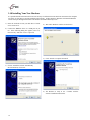
1
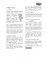
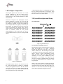
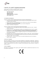
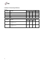
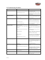
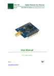
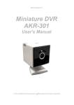
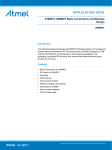
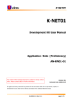
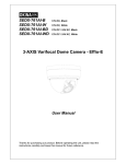
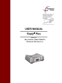
USER MANUAL Reply Plus Applies To: Base Station, Model WRS970 (Firmware Revision 3.x) Copyright 2007 -2008 Fleetwood Group, Inc., Electronics Division. All rights reserved. Licensed software products are owned by Fleetwood Group, Inc. or its suppliers and are protected by United States copyright laws and international treaty provisions. Fleetwood Group, Inc. products are covered by U.S. and foreign patents, issued and pending. Information in this publication supersedes that in all previously published material. Specifications and pricing are subject to change without notice. Printed in the U.S.A. Fleetwood Group, Inc. Electronics Division 11832 James St. Holland, Michigan 49424 www.fleetwoodgroup.com www.replysystems.com Sales: 1-800-257-6390 Technical Service: 1-888-GO-REPLY (467-3759) Reply® is a registered trademark of Fleetwood Group, Inc. Other trademarks contained herein are the property of their respective holders. Revision History: ii Rev Date Description A 07/14/08 Revision 2.x Original B 07/07/09 Update Fleetwood Group Logo C 12/15/09 Updated for revision 3.x firmware D 2/8/2010 Updated the WiFi Avoidance Tables E 5/5/2010 Updated Text and Patent information F 5/25/2011 Updated Patent information Table of Contents 1.0 REPLY® SYSTEMS ............................................................................................................................................. 1 1.1 INTRODUCTION .................................................................................................................................................... 1 1.2 APPLICATIONS/ADVANTAGES .............................................................................................................................. 1 1.3 RF COMMUNICATION ........................................................................................................................................... 1 1.4 TECHNOLOGY LEADERSHIP, PATENT PROTECTION, AND CERTIFICATION ............................................................ 1 1.5 OTHER FLEETWOOD GROUP, INC. PRODUCTS ...................................................................................................... 1 2.0 PRINCIPLES OF OPERATION ......................................................................................................................... 2 3.0 SYSTEM DESCRIPTION AND SETUP ............................................................................................................ 2 3.1 ROOM LAYOUT .................................................................................................................................................... 2 3.2 PLACEMENT OF THE REPLY® SYSTEM .................................................................................................................. 2 4.0 CONNECTING THE BASE ................................................................................................................................ 3 4.1 CONFIGURE BASE FOR CONNECTION TYPE .......................................................................................................... 3 4.2 USB ..................................................................................................................................................................... 3 4.3 ETHERNET............................................................................................................................................................ 3 4.4 SOFTWARE ........................................................................................................................................................... 3 5.0 SYSTEM INFORMATION ................................................................................................................................. 3 5.1 LCD POWER-UP SEQUENCE ................................................................................................................................ 3 6.0 SYSTEM SETTINGS ........................................................................................................................................... 4 6.1 SESSION NAMING ................................................................................................................................................. 4 6.2 RF PERFORMANCE ............................................................................................................................................... 4 6.3 OTHER SETTINGS ................................................................................................................................................. 5 7.0 WRS970 DATA FORMAT AND COMMAND LISTS...................................................................................... 6 8.0 SOFTWARE.......................................................................................................................................................... 6 9.0 ACCESSORIES .................................................................................................................................................... 6 10.0 LIMITED PRODUCT WARRANTY ............................................................................................................... 7 11.0 FCC, IC, AND EU COMPLIANCE INFORMATION.................................................................................... 8 11.1 STANDARDS AND GUIDELINES ........................................................................................................................... 8 11.2 FCC/IC COMPLIANCE ........................................................................................................................................ 8 11.3 EU COMPLIANCE ............................................................................................................................................... 8 12.0 BASE TECHNICAL SPECIFICATIONS ...................................................................................................... 10 13.0 TROUBLESHOOTING PROCEDURES ....................................................................................................... 11 14.0 INSTALLING YOUR NEW HARDWARE ................................................................................................... 12 15.0 INDEX................................................................................................................................................................ 13 iii ® 1.0 Reply Systems 1.1 Introduction This product consists of wireless (RF) handheld 15key numeric keypads and a Base Station. The system is generally used to record answers to multiple choice questions as part of a classroom presentation, decision-making session, focus group, or videoconference. It offers methods for collecting and immediately reporting group response. Reply® systems have been available for over 20 years and millions of Fleetwood Group keypads are currently used worldwide. Reply® is a cordless handheld response system that provides numeric data interaction for meeting or learning environments. Keypad responses are transmitted to the Base Station, which processes and delivers the information to the attached computer. Application software operates the Base Station and controls its associated Keypads. While the system’s hardware may offer powerful features, application software is the essential ingredient in applying the technology to generate useful results. 1.2 Applications/Advantages Many meeting and learning venues require a mechanism for audience interaction. Moreover, many seek a method of automating surveys and grading activities. Reply® meets the need for such an interactive tool, bringing everyone together and instantly allowing measurement of interest, understanding, and involvement. Audience members can participate from their seat and personally indicate their opinions, ideas, and knowledge. Results of the interaction are immediately available, and their display offers presenters a valuable insight into the opinion and comprehension level of audience members. System setup typically involves handing a Keypad to every participant and connecting the Base Station to a computer. No Keypad wires or cabling need be installed prior to use. This allows fast, reliable, safe, and attractive installation. 1.3 RF Communication The Keypads communicate with the Base Station using wireless Radio Frequency (RF) technologies. The patented proprietary design has been rigorously tested and optimized for reliability and collection speed. 1.4 Technology Leadership, Patent Protection, and Certification Fleetwood Group, Inc. maintains a leadership position in wireless development of audience response solutions. United States Patents: 6,665,000, 5,724,357, 7,599,703 B2, 7,277,621 B2, 5,379,213, 7,746,820. European Patents: 0 069 773 B1, 1 427 278 B1, 1 478 099 B1 reflect the commitment to wireless technology leadership and the unique position that Fleetwood Group, Inc. brings to the market. Additional United States and foreign patents are pending. Fleetwood Group, Inc. also maintains a commitment to complying with the United States Federal Communications Commission and various foreign regulatory requirements. Others are continuously being added. Please contact your reseller or Fleetwood Group, Inc. for more information on certification. 1.5 Other Fleetwood Group, Inc. Products Fleetwood Group, Inc. is a manufacturer of quality electronic products that are sold through a worldwide reseller network. All Reply® products are designed and manufactured in Holland, Michigan. For more information on these products or our customization capability, please visit our website at www.replysystems.com. 1 2.0 Principles of Operation This Reply® System uses the latest in 2.4 GHz wireless technology to turn any meeting into a dynamic interactive experience for each participant without having to deal with the difficulties of cables and connectors. Fleetwood is unique in the marketplace with its patented technology to provide a two-way link with the keypads. This design ensures that no responses are missed by requiring a keypad to retransmit the user’s response until it is properly received by the Base Station. The design also allows the system to refuse to acknowledge any invalid entries. This is clearly superior to other technologies using one-way radio or infrared, which do not provide acknowledgment to the keypad when its entry is received and do not have any way of rejecting invalid entries. A radio frequency packet is continuously sent out by the base station when the unit is powered on. Each base station’s packet can only be received by keypads that have been set to the same channel. 3.0 System Description and Setup 3.1 Room Layout Base Station Computer Projector Figure 2. Typical Room Layout 3.2 Placement of the Reply® System Figure 1. System Diagram The WRS970 Base Station is the control center for the system and operates according to commands issued by the application software. The Base Station can be set to any of the 31 available channels through the WRS970 OCX module. Each Base Station can process responses from up to 500 keypads. 2 The Base Station can be located anywhere in the area where the keypads are to be used. WRS7200 keypads can operate in a room up to 650’ x 650’ (200m x 200m) in size. The total range of the system is determined by the base and keypad, whichever is shorter. Despite a robust communication system, walls and some other 2.4 GHz devices can moderately to severely limit the WRS970 system’s performance. If coverage of a larger area is necessary, elevation of the Base Station or centering in room can usually improve the reception of the keypad signals. NOTE: Due to the properties of signals operating at 2.4 GHz, Fleetwood does not recommend placing any walls between the base station and the keypads. The material in a wall tends to absorb the RF signal and some reduced performance might be observed. 4.0 Connecting the Base Power-over-Ethernet (PoE) MIDSPAN capability. PoE is a technology that supplies power and data through the one Ethernet cable up to 300’ (100 m). For single base installations, a PoE Injector connects between the PC and the Base stations near the power source (Figure 4). Contact a Fleetwood dealer for the optional PoE accessory kit. For multiple base installations, a third-party PoE Midspan hub, router or switch may be a better solution. Data Figure 3. WRS970 Base Station Computer PoE Injector Power & Data Base 4.1 Configure Base for Connection Type The WRS970 provides two options for connecting to a PC: USB and Ethernet. Both types of connections can be connected to the Base unit simultaneously. However, the Base can only communicate through one of the two. No buttons exist as the Base determines the connection method based how power is first applied to the unit. If power is first connected using USB, USB is selected. If power is first applied using the external DC jack or the built-in PoE, Ethernet is selected. The base will present on the LCD at power up which connection is activated. 4.2 USB For the initial USB connection, internet access is recommended for obtaining drivers. If internet is not available, insert the Hardware Manual CD that came with the WRS970 Base Station. (See Section 14.0). The USB connection is capable of powering the base unit along with the data connection. Connect the included USB cable to the base and the other end to an open USB port on the PC or hub. If prompted by Windows, select to install the drivers automatically. See Section 14.0 for driver installation instructions. The PC alerts when the hardware is installed and ready to use. 4.3 Ethernet An Ethernet connection is provided for installations where the Base Station may not be within a USB cable length of the PC. To connect directly to the PC, an Ethernet cross-over cable must be used. For connection through a hub or similar device, a standard Ethernet cable will suffice. To use Ethernet, the optional accessory kit for Ethernet connectivity is available which includes the AC-DC adaptor and standard Ethernet cable. Base installation locations that do not have a power source nearby can take advantage of the WRS970’s Power Figure 4. PoE Midspan Connection Each base unit ships from the Fleetwood factory with a default IP address of 200.0.0.78, subnet mask of 255.255.255.0 and port 2101. If Ethernet is the desired connection type, see your network administrator to ensure the settings are compatible with your network. A built-in web interface is available to configure the device Ethernet settings (username: root; default password: dbps). Important! After connecting power to the base unit for use with Ethernet, the base requires a 30 - 40 second wait period for the base to configure its network connection before the software application can connect via Ethernet. 4.4 Software Activate the Reply® WRS970 compliant software application. Connect to the Base Station (see your software user guide for further instructions) and start a polling session. The system is now ready to process responses from assigned keypads. Two-way radio communication is now operational between the Base Station and keypads. 5.0 System Information 5.1 LCD Power-Up Sequence The LCD display on the base unit displays information about the base unit when the unit is first powered. 3 Next the base will display the connection type determined. If the connection type displayed is not the connection intended to use via software, refer to Section 4.0. The next screen displays the current base firmware level. For this manual, the firmware level must be above 3.00. The next screen is the serial number assigned to the base station. It is the same number that resides on the label on the underside of the base unit. The image below is shown as an example. Finally the LCD will rest at its normal operating screen. It displays the current Base ID which is required to uniquely identify separate systems. 6.0 System Settings 6.1 Session Naming Version 3.x firmware supports the ability to name a polling session. A session name if set displays in place of the Base ID on the keypad. Up to 8 4 characters can be used and will display on the LCD of the base station on the top line as shown below. If no session name is entered or a blank name is set, the top line of the LCD will display the Base ID label again. Session name does not uniquely identify a base or system. Each base must still have a unique Base ID set to it. Session names are not stored if the base is disconnected from power. Each time a session is started, the name, if desired, will need to be set, through software. 6.2 RF Performance The WRS970 system is frequency hopping to avoid interferences from other products. However, a heavily used wireless internet access point can make certain frequencies more difficult to transmit on. There are three commonly used channels for Wi-Fi access points: Channel 1, 6 and 11. The Reply® WRS970 system can be set up to avoid 1 to 2 of these channels if needed. The available settings are displayed in Table 1. See your network administrator for help in determining the optimum setting. Table 1. Wifi Channel Avoidance Settings Avoid Frequencies Avoided Low Avoid 2401MHz to 2425MHz (avoid Wi-Fi channel 1) LowMid Avoid 2401MHz to 2450MHz (avoid Wi-Fi channels 1 and 6) LowHigh Avoid 2401MHZ to 2425MHZ and 2450MHz to 2475MHz (avoid Wi-Fi channels 1 and 11) Mid MidHigh Avoid 2425MHz to 2450MHz (avoid Wi-Fi channel 6) Avoid 2425 to 2475MHz (avoid Wi-Fi channels 6 and 11) High Avoid 2450MHz to 2475MHz (avoid Wi-Fi channel 11) None Use full band of frequencies for hopping. Table 2. Power Level Settings If there are three or more access points covering the entire band, the WRS970 system can be configured to use a higher power level setting. The level is only certified for use in the United States and Canada. (See Table 2). Power Level For areas that don’t have wireless internet issues but are using multiple Reply systems in nearby rooms, it is recommended to lower the power level setting to avoid system interference. Set the power to what is necessary to reliably cover the room or area in which the system will operate. The power level options are displayed in Table 2. Power (mW) Low 0.01 mW Mid 0.1 mW High 0.3 mW Europe Max 1 mW (default for all systems) US Max 13 mW Figure 5. WiFi Frequency Avoidance Reply® Plus WiFi Avoidance Settings Channel 1 Channel 6 Channel 11 Avoid Low/Mid Channel Avoid Low/High Channel Avoid Mid/High Channel Avoid Mid Channel Avoid Mid Channel Avoid Low Channel Avoid High Channel No WiFi Avoidance 2401 2410 2420 2430 2440 2450 2460 2470 2.4 GHz Band (MHz) KEY - Typical WiFi Channels - Reply® Plus Frequency Usage 6.3 Other Settings Most system settings are set via software through the base station to control keypad behavior. See your specific software program help to determine what features are available. 5 7.0 WRS970 Data Format and Command Lists The Base Station data format, command lists, and associated microcode are proprietary to Fleetwood. People who wish to develop their own applications may purchase the Reply® WRS970 API. This is a software developer’s toolkit that includes the necessary communication drivers for the base station. 8.0 Software Off-the-shelf software packages are available for Reply®. These packages are available through Fleetwood’s network of qualified dealer-developers. Most Reply® compliant software applications require the Windows operating system (trademark Microsoft Corporation). Contact Fleetwood for details on the software applications that are certified for use with Reply® products. 9.0 Accessories Call Fleetwood or an authorized dealer for information on available storage/shipping cases, extra cables or power supply kits. 6 10.0 Limited Product Warranty Fleetwood Group, Inc. warrants its Reply Wireless Response System components for a period of 24 months from the date of manufacture for any material or workmanship defect in the product. This warranty does not extend to batteries or any product component, which has been subjected to misuse, neglect, accidental breakage, improper installation, use outside of present guidelines, or alteration outside of our factory. Reply Base Stations and Keypads use internal antennas built directly on the printed circuit board. Modifying the antennas in any way will result in reduced range and will void the warranty. There are no user serviceable parts inside Reply Base Stations or Keypads. Fleetwood Group, Inc. agrees to remedy, at the factory, any product defect, or at its discretion, replace any component or part of the product provided the owner complies with the following procedures: 1) The owner is to determine that the problem is not the battery or a faulty or improper connection with the personal computer or power source. The owner will contact our Product Service Coordinator during standard hours Monday through Thursday 7:00 AM to 3:30 PM and Friday 6:00 AM to 12:00 PM Eastern Standard Time at 1-888-GO REPLY (467-3759) or www.replysystems.com/rma/ to obtain a Return Material Authorization (RMA) number prior to shipping the product back to the factory. 2) The owner will send the defective component via prepaid freight to: Fleetwood Group, Inc. Electronics Division Product Service Coordinator RMA#: 11832 James Street Holland, MI 49424 3) If the factory determines the defect is due to negligence or oversight on the part of the owner, the owner will be invoiced for the cost of the repair. 7 11.0 FCC, IC, and EU Compliance Information WRS970 Reply® Base Station and WRS7200 Reply® Keypad Responsible Party Pertaining to the Declaration of Conformity Fleetwood Group, Inc. 11832 James Street Holland, MI 49424 Attn: Product Service Coordinator Phone: 888-467-3759 11.1 Standards and Guidelines This device complies with the following European Directives and USA/Canada Regulations: Directive 1999/5/EC on radio equipment and telecommunication terminal equipment and the mutual recognition of their conformity Directive 2006/95/EC on the harmonization of laws of member states related to electrical equipment designed for use within certain voltage limits The USA Federal Communications Commission (FCC) Rules and Regulations Industry Canada Rules and Regulations This device complies with the following national and international standards: EN 301 489-1 V1.6.1: 2005: EMR; EMC standard for radio equipment and services. Part 1: Common technical requirements. EN 301 489-17 V1.2.1: 2002: EMR; EMC standard for radio equipment and services. Part 17: Specific conditions for 2.4 GHz wideband transmission systems and 5 GHz high performance RLAN equipment. EN 300 328 V1.7.1: Electromagnetic compatibility and Radio spectrum Matters (ERM);Wideband transmission systems; Data transmission equipment operating in the 2,4 GHz ISM band and using wide band modulation techniques. EN 60950-1: 2001 + A11: 2004: Information technology equipment – Safety. Part 1: General requirements FCC Part 15B, 15.247: 10-01-2006: Radio Frequency devices: Operation within the bands 902-928 MHz, 2400-2483.5 MHz, and 5725-5850 MHz. IC RSS-210 Issue 7: 2007: Low power license-except radio-communications devices (all frequency bands): Category 1 equipment. 11.2 FCC/IC Compliance This device complies with Part 15 of the FCC Rules and RSS-210 of the Industry Canada Rules. Operation is subject to the following two conditions: (1) this device may not cause interference and (2) this device must accept any interference, including interference that may cause undesired operation of the device. The user is cautioned that changes or modifications to the device that are not approved by the manufacturer could void the user’s authority to operate the device. 11.3 EU Compliance This device is a 2.4 GHz low power response system controller intended for residential and commercial use in all EU and EFTA member states. 8 Notice The base and keypad units may be susceptible to Electrostatic Discharge (ESD) and other similar fast transient events causing system interruption. Should system interruption occur, reboot computer, reset base unit by disconnecting and reconnecting USB cable and push any key on keypads which have powered down. 9 12.0 Base Technical Specifications Enclosure Symbol Parameter Value Unit Min Typ Max dl Length - 4.95 - in. (mm) dw Width - 6.25 - in. (mm) dh Height (Thickness) - 2.25 - in. (mm) wb Weight - 0.60 - lbs Power Symbol VDD 10 Parameter Supply Voltage DC Jack Power-over-Ethernet USB Current Consumption DC Jack Power-over-Ethernet USB Value Min Typ Max 4.2 39 4.75 6 48 5 6.9 55 5.25 360 360 60 - 600 600 300 Unit V mA 13.0 Troubleshooting Procedures ISSUE POSSIBLE CAUSE SOLUTION The backlight is in the always on state. If backlight is needed, use the on key press or acknowledgement settings. Non-alkaline batteries were used. Rechargeable batteries offer the ability or reuse but may have a shorter run time than alkaline batteries. Batteries may be inserted backwards. Pull the batteries out and check the orientation symbols in the bottom of the battery cavity. Batteries are dead. Replace the batteries. Normal Cable used for direct PC connection. A cross-over cable must be used between the base and PC. A normal Ethernet cable is for base to hub, switch, and router connections. Base Unit not powered. Plug in the power supply to the base station. Device not configured properly. See network administrator to configure base station. See Section 4.3. Base not in open area. Do not place the base inside cabinets. Base located too close to other electronic equipment Place the base away from other electronic devices, such as TV’s, DVD/VCR players and similar. More than one base unit on the same Base ID Check that the bases covering an area are not on the same Base ID. WiFi RF Interference Verify the WiFi avoidance settings are set correctly in the software. See your network administrator for channel settings. Other Interference Always physically separate other radio devices by at least 10’ (3 m). This includes WiFi, Bluetooth, ZigBee and other similar devices. Multiple Base Stations are too close Keep base stations separated and do not stack units. Power level setting too low. Check that the power level setting of the system is appropriate for the range trying to be achieved (Some countries have restrictions as to the power level setting allowed. See Section 11.0). Interference See “Poor RF Performance”. Keypad and base in static mode but Base ID are not matched. Change either the keypad or base so they match. Keypad is static mode, base is dynamic mode. Change either the keypad or the base to the desired operational mode. The two modes are not compatible with each other. See Section Error! Reference source not found.. Keypad won’t authorize Base station the keypad tried to connect to has been disconnected. Press SEARCH key again and select a new base. Base not found to connect to Drivers not installed or can’t be found. Connect to the internet and then connect the base unit or if no internet, insert the CD that came with the system. Keypad Battery Life is short Keypad does not turn on No Ethernet communication Poor RF Performance Short range with keypads Keypad vote not sending 7/31/2007 14.0 Installing Your New Hardware It is possible that the instructions below are not necessary if a different base unit has been connected to the computer previously or if the driver is already installed on the computer. In those instances, Windows will install behind the scenes and report through balloons that “The hardware is installed and ready to use.” 1) Insert the enclosed CD into your disk drive if internet access is not active. 4) Wait while Windows searches for the drivers. 2) Connect the WRS970 device to a USB port on your PC. If the following dialog box appears, select “Yes, this time only” and Click “Next” to proceed. 5) Click “Finish” to complete the install. 3) Choose “Install the software automatically (Recommended)” Click Next. 6) The hardware is ready to use. software installation instructions. 12 Continue with the 15.0 Index RF Performance, 4 A S Accessories, 6 E Service, ii, 7 Software, 6 Ethernet, 3 T F Technical Specifications, 10 Troubleshooting, 11 Fleetwood products, 1 U I Universal Serial Bus (USB), 3 Interface, 6 W P Patent information, 1 R Return Parts, 6 RF communication, 1 7/31/2007 Warranty, 7