1
Manual for Installer and User
Fury
Digital Video Recording Systems
Ref. Models
All Fury products
DW-Pro-9200 Series
DW-Pro-42000 Series
Introduction
Thank you for purchasing Fury DVR
Fury products have been designed and manufactured with advanced technology developed
by Digital Watchdog in compliance with international safety standards. It’s quality is
guaranteed by strict reliability and compatibility tests.
It is strongly recommended that you read this Manual carefully. As most of images and
features shown in this Manual are based on the latest model, some features of your
equipment may differ from those stated in this Manual.
This Manual is copyrighted and all rights are reserved to Kaltech Enterprises.
It is strictly prohibited to make copies of this manual without permission.
Kaltech Enterprises is not held responsible for any system failures or damage due to
disobeying manual instructions.
Fury is a registered trademark of Kaltech Enterprises,.
This capture board products has passed household, industrial and domestic radio wave
compatibility tests and is certified by CE and FCC.
Safety Precautions
When selecting a place for the DVR, avoid locations with :
Excessive heat, such as direct ray of light or heating appliances.
Excessive moisture, dust, or smoke.
Magnetic substances or electric wave equipments in close proximity.
Excessive hot or cold temperature (operating temperature from 5 C ~ 45 C)
Unstable or elevated surface.
Before proceeding further with this manual, make sure to follow the precautions below:
Plug the power cable in after connecting all devices. Connecting a device when the
power is on may cause problems. Do not forget that Fury DVR is automatically booted
when the power cable is plugged in.
Leave enough space around the DVR, avoid tangling cable lines and blocking ventilation.
Keep the DVR clean of dust and foreign objects.
In case of malfunction, do not try to repair the DVR by yourself. Contact local distributor
for assistance.
Fury Manual
2
Table of Contents
Preface
Introduction ------------------------------------------------------------------------ 2
Precaution ------------------------------------------------------------------------- 2
Table of contents ----------------------------------------------------------------- 3
Chapter 1 Installation & Setup
Installation
1.1
1.2
1.3
1.4
1.5
1.6
1.7
1.8
1.9
Unpacking ------------------------------------------------------------------ 6
Front view ------------------------------------------------------------------ 7
Rear view ------------------------------------------------------------------- 8
Installation procedure ---------------------------------------------------- 9
Connecting PAN/TILT drive ------------------------------------------- 10
Connecting PSTN, ISDN or leased circuit --------------------------11
External sensor connection -------------------------------------------- 12
External control connection -------------------------------------------- 12
Watchdog cable connection ------------------------------------------- 13
System Setup
1.10 System setup -------------------------------------------------------------- 15
1.11 Hardware setup ----------------------------------------------------------- 16
1.11.1 Cameras ---------------------------------------------------------------- 16
1.11.2 Sensors ----------------------------------------------------------------- 18
1.11.3 Controls ----------------------------------------------------------------- 19
1.11.4 External monitor ------------------------------------------------------ 20
1.12 Motion detection ----------------------------------------------------------21
1.13 Recording / Display ----------------------------------------------------- 24
1.14 Recording schedule ---------------------------------------------------- 26
1.15 Screen division ----------------------------------------------------------- 29
1.16 Modem --------------------------------------------------------------------- 30
1.17 Site information ----------------------------------------------------------- 33
1.18 Password ------------------------------------------------------------------- 36
1.19 Audio ------------------------------------------------------------------------ 37
1.20 System ---------------------------------------------------------------------- 39
1.21 Motion tracking ------------------------------------------------------------ 48
1.22 Storage---------- ------------------------------------------------------------ 49
1.23 E-Map ------------------------------------------------------------------------ 52
Fury Manual
3
Table of Contents
Chapter 2 Operation
Surveillance Mode
2.1 Surveillance mode ----------------------------------------------------- 55
2.2 Pan/Tilt Mode ----------------------------------------------------------- 57
2.3 Pan/Tilt control for P/T/Z cameras --------------------------------- 58
2.4 Pan/Tilt control for speed dome cameras ------------------------ 59
2.5 Live audio ---------------------------------------------------------------- 61
Search Mode
2.6 Entering into Search mode ---------------------------------------- 63
2.7 Search by date & time ---------------------------------------------- 64
2.8 Intelli search ----------------------------------------------------------- 65
2.9 Image control ---------------------------------------------------------- 68
2.10 Search options ------------------------------------------------------ 69
2.11 Index search --------------------------------------------------------- 70
2.12 Object search ---------------------------------------------------------71
2.13 Video playback ------------------------------------------------------ 74
2.14 Audio playback ------------------------------------------------------ 75
2.15 Printing ---------------------------------------------------------------- 76
2.16 Full-screen mode --------------------------------------------------- 77
2.17 Bookmark ------------------------------------------------------------- 78
2.18 Backup ---------------------------------------------------------------- 79
2.18.1 Floppy backup ------------------------------------------------- 80
2.18.2 Time backup --------------------------------------------------- 83
2.18.3 AVI backup ----------------------------------------------------- 85
2.18.4 E-mail backup ------------------------------------------------- 88
2.18.5 Common backup options ----------------------------------- 89
Appendices
A. Backup files -------------------------------------------------------------- 91
B. Receiver Board Layout
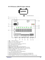
B.1. RX-Receiver (KRE-301) layout ------------------------------ 92
B.2. RX-Receiver (KRE-302) layout ------------------------------ 93
C. User management ----------------------------------------------------- 94
D. Windows audio setup ------------------------------------------------ 106
Index ------------------------------------------------------------------------ 108
Warranty ------------------------------------------------------------------- 110
Fury Manual
4
Chapter 1 Installation & Setup
Installation
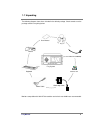
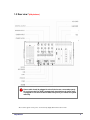
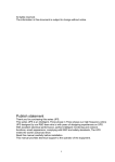
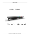
1.1 Unpacking
The following diagram shows items included in the default package. Check to make sure the
package contains everything below.
User Manual
Key
Mouse
Communication conversion cable
(used for PAN/TILT CAMERA)
Fury System
Software CD
Keyboard
Power Cable
Watchdog Cable
Monitors compatible with 1024 X 768 resolution and refresh rate of 60Hz are recommended.
Fury Manual
6
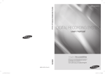
1.2 Front view (old pictures)
Front and rear design may vary depending on Fury Model
Fury Manual
7
1.3 Rear view *(old pictures)
!
Power cable should be plugged in after all devices are connected properly.
Do not forget that Fury DVR is automatically booted when the power cable
is plugged in. Use the front On/Off Switch only when you reboot the system
manually.
* Above view is typical for Fury series. Your model may slightly differ from the above in view.
Fury Manual
8
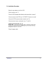
1.4 Installation Procedure
Follow the steps below to install the DVR:
-Check inventory (see 1.1)
-Place the DVR to proper place following safety precautions in page 2.
-Connect cameras to the DVR (see 1.5 if PAN/TILT cameras are used)
-Connect the DVR to communication network (see 1.6)
-Connect external sensors and controls (see 1.7 and 1.8)
-Plug in the watchdog cable (see 1.9)
IMPORTANT: unconnected watchdog cable is common mistake when
installing Fury DVR and causes rebooting every 10 minutes that may
damage the hard disk in the DVR
-Plug in the power cable
Fury Manual
9
1.5 Connecting PAN/TILT drive
RUN LED
TXD LED
RXD LED
EXTERNAL MONITOR
SIGNAL ( + )
Remote Controller Receiver
RS-422 Connection
(from RX-Receiver)
Not in use
RS-232 Connection
(from Com1 port)
!
SIGNAL ( - )
Make sure positive (+) and minus (-) signs are correct. Connecting to wrong side may cause
damage to the system.
Please contact your distributor when using other RX Receiver brand.
Fury Manual
10
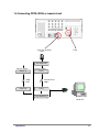
1.6 Connecting PSTN, ISDN, or leased circuit
Connection to COM 2
( 9 PIN )
PSTN
A/C ADAPTER
RS-232 ( 25PIN )
ISDN T.A.
RS-232 ( 25PIN )
D.S.U
Leased Circuit
ISDN
LINE
ISDN T.A.
COM 2
D.S.U
A/C ADAPTER
Center PC
Fury Manual
11
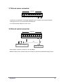
1.7 External sensor connection
SENSOR
1
2
3
4
5
6
7
8
COM
Infrared rays, heat detection, and magnetic detection sensors should be connected to COM port.
Other type of sensors can be connected to SENSOR port.
Use individual power adapters for each sensor.
1.8 External control connection
CONTROL
1
2
3
4
5
6
7
(
Alarm, Siren, Relay etc.
8
COM
(
)
)
Power (DC 12V)
Power adapters should be no more than 12V and 300mA.
Additional external relay should be used to turn controls on and off when powered through AC input.
Fury Manual
12
1.9 Watchdog cable connection
" !$#%&#&')(&*,+ In addition to watchdog function, Watchdog Cable is also used to:
• Enable Sensor function
• Enable Control function
• Enable P/T/Z function
• Enable External monitor output function (may vary depending on model)
Fury Manual
13
Chapter 1 Installation & Setup
System Setup
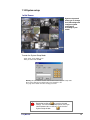
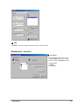
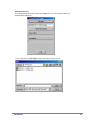
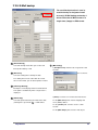
1.10 System setup
Initial Screen
System setup mode
allows you to change
the DVR settings and
configure system
environment
according to your
needs.
To enter the System Setup Mode:
-Click Setup on the initial screen.
-Enter password and click Ok.
Warning: The password is used to enter Search mode or System Setup mode.
Please write down the password and keep it somewhere safe.
See page 36 for details on how to change password.
!
Fury Manual
Remember to click on
to save the changed
settings. The DVR will not prompt you to save if you
switch between tabs or click on
to close the
System Setup window
15
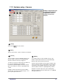
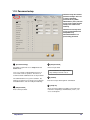
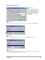
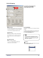
1.11.1 Hardware setup - Cameras
2
3
Hardware setup allows users
to modify external devices
configurations, such as
cameras, sensors and
controls.
4
1
1
[Setup]
Check the box
to use the camera.
2 [Name]
Type in camera names. Up to 14 characters are allowed.
3 [Sensor]
You can connect sensors to available cameras. This
function enables cameras to record automatically
when the connected sensor(s) is triggered.
To connect a sensor to a camera, type the number of
the sensor in appropriate camera number.
If you wish to connect multiple sensors to a camera,
type sensor numbers in the box, separating them by
comma.
Example: In order for Camera 4 to start recording
when Sensor 1 or Sensor 3 is triggered, type “1,3” in
[Sensor] box against Camera 4
Fury Manual
4
[Motion]
You can link cameras to other available cameras. This
function enables linked cameras to record automatically
when the main camera detects movement.
To link a camera to another camera, type the number of the
camera you wish to connect in appropriate camera number.
If you wish to connect multiple cameras to a camera, type
camera numbers in the box, separating them by comma.
Example: In order for Camera 5 to start recording when
Camera 1 or Camera 2 detects motion, type “1,2” in [Motion]
box against Camera 5
16
5
6
7
5 [P/T]
Check the box
6
if the camera is of PAN/TILT type.
[Type]
Use the scroll bar to select PAN/TILT camera model from the list.
This option box is disabled if [P/T] box 5 is not selected
7
[Emergency]
Select a preset location where Pan/Tilt camera will return to when any linked sensor is triggered.
Fury Manual
17
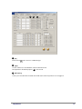
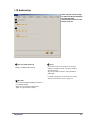
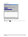
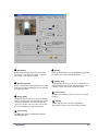
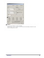
1.11.2 Hardware setup - Sensors
2
1
3
4
1 [Setup]
Check the box
to enable sensors. Unchecked
the box to disables sensors.
2 [NC/NO]
Choose sensor type. Click the button to switch
between [NC] and [NO] sensor types.
• NC = Normally Close type. If the door/object with
the sensor installed is not closed, the sensor will
trigger.
• NO = Normally Open type. If the door/object with
the sensor installed is not open, the sensor will trigger.
Fury Manual
3
[Use alarm]
Selecting [Use alarm] will enable the built-in internal
speaker to beep if a sensor is triggered. The speaker
however will not beep if the corresponding camera
schedule is set to Continuous Recording (see page
26).
4 [Recording Time]
Select the number of seconds to record when a
sensor is triggered. This function will not work if the
recording schedule is not set to Sensor or Motion
(see page 26).
18
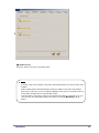
1.11.3 Hardware setup - Controls
Controls are used to turn on
and off sirens, alarms, lights
… when certain events occur
e.g. motion detected or a
sensor triggered.
2
3
4
5
1
1
Check the box
2
4 [Sensor]
[Setup]
to use the controls.
[Name]
Type in control names. Up to 14 characters are
allowed.
3 [Auto On/Off]
Auto function automatically activates controls
during selected time. To enable Auto function,
choose the time from scroll list. Default is set from
00:00 to 24:00.
Fury Manual
To connect a sensor to a control, type the number of the
sensor on appropriate control number.
If you wish to connect multiple sensors to a control, type
the sensor numbers in the box, separating them by comma.
Example: In order to turn on Control 3 when Sensor 1 or
Sensor 2 triggers, type “1,2” in the box against Control 3.
5 [Working sec]
Assign how long the control will stay active once it is
triggered. Maximum is 255 seconds and default is 0
seconds.
19
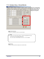
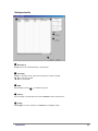
1.11.4 Hardware Setup – External Monitor
Home TV or normal analog
monitor can be used as an
external monitor to view
images from Fury DVR.
1
2
3
1
[Select time (Sec)]
Select time for displaying a channel on external monitor.
.
[Tip]
Images from external monitor output use Split Screening Method instead of
Consecutive Conversion Method with the Fury
The screen on the external monitor is the same as seen on the DVR.
2
[Camera]
Select the channel you wish to display on the external monitor.
Fury Manual
20
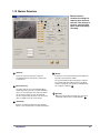
1.12 Motion Detection
1
3
4
2
4a
5
1
3
5a
Motion Detection
contains the settings for
cameras when motion is
detected. This function is
useful to save hard disk
space from unnecessary
recording.
4
2
5
1
[Camera]
Select the camera you wish to setup. The
description below is related to the camera you
selected here.
2 [Detection Area]
To enable cameras to record automatically by
motion detection, you mush select the detection
areas. To select detection area, place the mouse
cursor over the channel screen and drag the
cursor in any direction you wish. You can assign
up to 5 separate areas for each camera.
4 [Alarm]
If the box is checked, the internal speaker will beep
when the camera detects motion.
The speaker however will not beep if the camera is
set to Continuous Recording mode in Scheduled
Setup (see page 26). The speaker’s activation time
can set by the scroll lists 4a
5 [Control]
When the camera detects motion, the connected
control will activate for the designated time 5a
3 [Sensitivity]
Change sensitivity of motion detection. Default
value is set to 15 and it is the recommended value.
Fury Manual
21
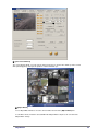
6
6
7
6 [Use Secure Channel]
The system displays blank screen for camera channels if the box is checked. This allows system to record
while protecting privacy from system operators or other unwanted eyes.
7 [Object Watch]
To use Object Watch function, select the camera number and check the [Object Watch] box.
In surveillance mode, if motion is detected within the Object Watch setup area, the cell color of the
Object Watch change.
Fury Manual
22
8
10
11
9
9
12
12
13
14
17
15
16
8 [Area Clear]
14 [Full screen when motion]
Delete Detection Area for selected camera. To manually
delete an area, simply drag the detection area outside
the channel screen.
The channels of the cameras specified in this box will
change to full screen if they detect motion. If you wish
to select multiple cameras, type the camera numbers
in the box, separating them by comma.
9 [Area Draw]
Assign entire channel view as detection area.
10 [Camera Adjustment]
Adjust brightness, hue and contrast for each camera.
Caution: Adjusting these options will affect recorded data.
11 [Color]
If the camera is black-and-white, click [Color] to change
the channel into Black and White. Default is set to Color
for all channels.
12 [Default]
Set values in 10 and 11 back to default.
15
[Delay Time (sec)]
Delay Time works in conjunction with [Full screen
when motion], and will freeze the channel if motion
is detected on cameras with [Full screen when
motion] enabled. To enable Delay Time, select the
number of seconds from scroll list.
16 [No full screen]
Cancels options set on [Full screen when
motion] and [Delay time].
17 [Color of Motion Area]
When a camera detects motion its channel will
highlight the Detection Areas by the color you
select here (Red or Green)
13 [Set quad rotation time]
Select rotation time for Channel Rotation. See
[Channel Rotation] on page 55
!
Do not set the time to 0. The channels will
rotate too fast.
Fury Manual
23
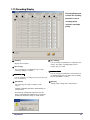
1.13 Recording/Display
Recording/Display tab
1
2
3
4
5
6
contains the recording
parameters such as
8
recording speed,
resolution and image
quality.
1
7
1 [Camera]
5 [Rec. Quality]
You can change the quality of the recording for each
camera. The higher recording quality the more
storage space is needed.
Display camera number.
2 [Rec. Frame]
You can change the recording frame rate of each
camera by sliding the scroll bar.
3
/ ;< =39?>@ :
You can change the recording speed of each camera in
case of emergency.
4 [Resolution]
You can change the image resolution of each
camera.
6
/ 0 1324 56317 8 9:
You can change the quality of the transfer image for
use during transmission. The higher transfer quality
the more bandwidth is needed.
7 [Default]
Change all the settings to the default values.
320x240 or 640x480 (384x288 or 768x576 PAL) are
recommended.
The DVR may automatically adjust the frame rate
when selecting 640x480 (768x576 PAL). You will be
prompted to confirm the change as shown below:
Fury Manual
24
.
Selection of Resolution, Rec. Quality and Transfer Quality under [All] 8
page 24) will apply the selected value to all cameras.
(see picture on
(Resolution by NTSC)
Default recording frame rate per channel for Fury
Channel
Recording Frame
4 Ch.
30 frames per second
8 Ch.
15 frames per second
16 Ch.
7 frames per second
When you increase the recording frame rate of any camera, the frame rate for other
cameras may decrease automatically.
Fury Manual
25
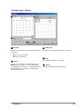
1.14 Recording schedule
Schedule setup tab
contains recording
schedules for each
camera
3
1
4
2
4 [Record Mode]
1 [Camera]
Select the camera you wish to setup. All the description
below is related to the selected camera.
Select Record Mode for selected time interval. If no mode is
selected, the system will not record. Default is Motion &
Sensor Record for 24 hours for all date of the year.
2 [Setting Recording Mode]
The table displays recording mode for every hour. To
change Record Mode, click on the hour you wish to
change ( you can drag mouse to select multiple boxes.
The selected time will be highlighted blue. Then change
the mode from Record Mode setting
4
To be exact to minutes, click on the time you wish to
change and a horizontal bar will appear:
Recording
Modes
• C: Continuous Recording
• M: Motion Recording
• S: Sensor Recording
• P: Pre-Alarm Recording
01 min
59 min
Simply slide the bar left or right to change minutes.
Supported recording
mode/combinations
• No recording
• Continuous recording
• Motion recording
• Sensor recording
• Pre-Alarm Recording
• Sensor & Pre-Alarm recording
• Motion & Pre-Alarm recording
• Motion & Sensor recording
• Motion & Sensor & Pre-Alarm
recording
3 [Simple/Advanced Mode]
In Advance Mode, you can set recording mode
separately for weekdays, Saturday and Sunday/Holiday.
!
Fury Manual
Motion Recording, Sensor Recording, and Pre-Alarm
Recording cannot be enabled in conjunction with
Continuous Recording.
26
5
6
5 [Copy To]
To copy the camera’s schedule to other cameras, click Copy To and select the camera number
you wish to copy to.
6 [Set holiday]
You can set any specific days as holiday (more details in page 28).
!
Do not forget to save after you make any change to Schedule.
Fury Manual
27
Schedule setup - Holiday
1
3
2
4
5
1 [Calendar]
Displays a calendar where you can designate any date
as a holiday.
•
•
ABA
CDC
Move to previous month.
Move to next month.
2 [Rotate]
To set the selected day(s) as monthly holiday, select
[Month] from the scroll list. To set as yearly holiday,
select [Year] from the scroll list. Leaving the option None
will designate the selected day(s) as holiday for that
specific month and year.
Fury Manual
3 [Holiday List]
Displays the list of designated holidays sorted by time.
4 [Add]
Click to add selected date(s) as holiday.
5
[Delete]
To delete a designated holiday from the list.
28
1.15 Screen Division
Screen division tab
contains the settings for
split screen modes
1
2
3
1
4
[Screen Division]
Screen division assigns which cameras will be
displays on which split screen mode. Select the split
screen mode you want to setup here.
4CH
6CH
9CH
10CH 13CH
16CH 33CH
36CH
If a split screen is supported by VIP (Video Interface
Port), VIP mark appears above the icon.
2 [Camera selection]
Select cameras to view in the chosen split
screen mode.
3 [Large screen]
When using 6,10, 13, or 33 split screen
mode, you can select which camera(s)
should be displayed on large channel(s).
If the camera has Video Interface Port,
[VIP] mark is followed by the camera
number.
4 [Default]
Set all options to default value.
Fury Manual
29
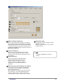
1.16 Modem
Modem setup tab
contains the settings for
communication of the
DVR.
In the description below,
“the Site” is referred to
the DVR itself, and the
Center PC is referred to
the PC connected to the
DVR.
1
2
5
3
4
6
1 [Type of connection]
LAN, PSTN, ISDN, Leased Circuit can be used for
remote connection.
6 [DDNS Setup]
If you wish to use DDNS, click on [DDNS Setup].
ISDN or Leased circuit with router connection is possible
and ISDN or PSTN can be used to connect to DVR
directly without router.
To disable remote connection, check the option box [No
connection].
2 [Password]
Enter 4-digit password to login to the site from the
Center PC.
[Password] : Enter the 4-digit numeric password
You can connect Center PC to Site DVR simply if
you input IP address which is linked with the
dynamic IP used by the Site user.
[Confirm] : Re-enter the password to confirm.
3 [Live Video stream bandwidth]
Set the communication bandwidth for transmitting video
image to the Center PC.
4 [Max Acceptable]
Set the maximum number of sites than can be
connected to the Center PC. One Center PC can
connect up to 120 different sites.
5 [Transfer secure channel]
.
[Tip]
When you try to connect to a Site from the Center
PC, system checks for the site code and
password, and if they are not identical, you will be
disconnected automatically.
(if the site program uses a dynamic IP, the Center
program cannot access the site program)
Check the option box to view the secure channel on
the remote Center PC.
Fury Manual
30
7
11
8
9
10
12
7 [Motion for Emergency Message]
When selected cameras detect motion, an emergency
message will be displayed automatically on Emergency
Monitor window on Center PC, provided Center Software
is installed and running. To specify the IP address of the
PC with Center program installed, enter the IP address on
[Emergency IP address].
8 [Sensor for emergency]
When selected sensors are triggered, the internal
speaker on Center PC will beep and the recorded
video of the connected camera(s) will be transferred to
the Center PC.
9 [Transfer time(sec)]
11 [Anonymous Login]
Check the box to enable anonymous login to
WebDVR via Internet.
Network security should be concerned when
using this function.
.
/ 0 8 E
:
For detail on WebDVR, refer to Center
Manual.
Indicates how long the recorded data will be
transferred to the Center PC when sensor is
triggered. Simply select the time from the
scroll list. If the sensor signal is re-triggered
during the transfer, the DVR will transfer the
data again.
10 [Emergency phone numbers/Emergency IP address]
If Site is connected to the Center PC through LAN or
Leased Circuit, enter the IP address for emergency
image or data transmission.
When using modem connection, and selected cameras
detect motion, the system will automatically dial the
number entered in the box. If it fails to connect, the
system will dial the numbers entered in the second box.
Fury Manual
31
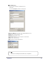
12 [Use E-Mail Service]
You can send an emergency recording data to your email account.
If you click on [Recipient], a window as below appears.
• [Mail Server (SMTP)] Enter the address of the outgoing (SMTP) mail server.
• [From] Enter the e-mail account of the sender.
• [Subject] Enter the title of the e-mail.
• [Mail Recipient List] Displays the list of recipients’ e-mail accounts.
• [ADD] To add a recipient to the list.
• [DEL] To delete an e-mail account from the list.
.
/ 0 8 E
:
For details on User Management and network setup see Appendix C
Fury Manual
32
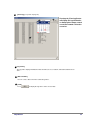
1.17 Site information
Site information tab
contains system-related
information such as Site
code, Site name, software
version, …. You can also
adjust Surveillance mode
options here .
1
2
3
4
1 [Site Information]
Displays Site Code, Location, Model, Distributor, Sales Date, and other related information. You can also
leave notes.
!
When logging onto the Site from the Center PC, the system checks the validity of Site code
and the correct password. If either is incorrect, the system will automatically disconnect.
2 [Camera status bar]
When enabled, the DVR displays camera recording status
in Surveillance mode.
3
[Sensor status bar]
When enabled, the system displays sensor status in Surveillance mode.
4
[Control status bar]
When enabled, the System displays control status in Surveillance mode.
Fury Manual
33
10
5
6
7
11
13
8
12
9
5 [Display motion detection grid]
When enabled, the channels with Detection Area will
display Motion Detection Grid in Surveillance mode
(see page 21 for Detection Area).
6 [Image transfer to floppy disk]
If this option is selected, the floppy backup (see
2.17.1) will save images in JPEG format. If
unchecked, the images will be saved in BMP
format (See 2.17 for details on Backup).
7
Displays the DVR model and Site software version,
Hard Disk Drive size, computer specifications, and
Windows Operating System information.
11 [Use Intelli Search tooltip]
If enabled, leaving the mouse cursor over a button
in Search mode will bring up tooltip for the button.
12 [Setting the System Clock]
[Disable Local Live]
When enabled, the image will not be displayed on
the screen while the system is recording.
8
10 [Site]
Change or correct your system clock.
[Date display format]
Adjusts date display format in Surveillance mode.
To change the date format, select a format from the
scroll list.
Load default time.
Save the selected time.
9 [Sensor Type] [Control Type]
Select 4, 8 or 16 sensors/controls to display their buttons
in Surveillance mode.
Fury Manual
.
The clock can be only forward but not
backward.
34
13
[View Log] (see picture on page 34)
2
3
Pressing the [View Log] button
will display the log information
on Setup option change, search
record and network connection
record etc.
1
1 [Log entries]
The log entries display information on date and time, the user, location, and actions that have been
done
2 [Date and Time]
You can select a date to view the recorded log entries.
3 [View]
Press
Fury Manual
to display the log entries of the selected date.
35
1.18 Password setup
Password setup tab contains
password settings. There are
3 levels of password
protection in Fury DVRs.
Administrator (level 1) has full
access to the system and can
modify Level 2 and Level 3
authority.
1
5
2
3
Password is used to protect
access to Search Mode and
Setup Mode only.
Surveillance Mode is not
protected by password.
4
1
[Password change]
Password is required to access Setup mode and
Search mode.
3
Enter new password.
Password must be 4-digit numbers
By default password is not set
Level 1 user works as administrator and users of
Level 2 and 3 work as operators. Therefore it is
recommended for administrator to set all passwords.
The administrator has no system restrictions, has
privileges to change Level 2 and Level 3 restrictions
and authorizations, and can modify their authority.
2 [Old password]
Enter current password.
Fury Manual
[New password]
4
[Confirm]
Enter the new password again for confirmation.
5 [Setup list]
Check on various options to modify Level 2 and Level 3
restrictions and privileges. Administrator (Level 1) can
access to all options.
36
1.19 Audio setup
Audio setup tab contain settings
for audio recording and playback,
live audio and audio
communication between the Site
and the Center PC.
1
2
3
1 [Can use audio channel 8]
3 [Live]
Displays available audio channels.
If you wish to listen to live audio on one channel
under the surveillance mode, click on the channel
you wish to listen.
The selected channel must be connected with an
audio input.
For details how to listen to more than 1 live audio
channel in Surveillance mode see page 74
2 [Record]
Select camera number with which you wish to
record audio together.
Audio can be recorded only when video
signals are captured for recording.
Fury Manual
37
4
4
[Audio out test]
Select the channel to check the sound output status.
.
/ 0 8 E32:
If a built-in sound card is installed, 2-way audio communication between the Center and the Site is
available.
Audio recording function will automatically stop when you initiate 2-way audio communication.
When using a sound card, you must change the Windows sound setup to record audio and to use
2-way audio communication (See appendix D for details).
In the Surveillance mode when a channel connected with a microphone is made full screen, you
can listen to the live audio together with the live image (See page 68 [Maximizing 1 ch] for
details).
Fury Manual
38
1.20 System setup
System setup tab contains
additional hardware settings,
backup schedule, watermark
settings and system-off
settings.
1
3
4
2
1
[System off time]
Assign the DVR to turn off automatically during selected
day and hours. To set System off time, select the days
and choose time from the scroll list.
2
[System restart time]
Assign the DVR to restart on daily basis on selected time.
Regular restarts make the DVR more stable and lower the
risk of errors. To set System restart time, check on Used
and select time from scroll list.
3
[Use Watermark]
Enable or disable Watermark feature.
4
!
What is Watermark?
BMP or JPEG images can be modified by
unauthorized ones, and modified images can
look just as realistic as original images.
Watermark feature helps to distinguish
between the original images and modified
images. When the System saves an image
onto its Hard disk drive, it will encode each
image with Watermark (provided you have
Watermark feature enabled from System
Setting), leaving a “mark” on each image.
When an image is modified, the “mark” will
change, therefore allowing the system to
differentiate between modified images and
original images.
[Display Watermark protect image]
When enabled, the channels display “Watermarked” on
the top right corner of all channels.
Fury Manual
39
8
5
9
6
5
7
7
10
68
11
9
12
9
10
5 [Backup settings]
Configure backup schedule (see page 56 for details)
6 [Easy Update!]
To update the system software, click [Easy
update] button (see page 61 for details).
11
9 [Video Loss Alarm]
The DVR can be setup to beep, activate alarm or raise
alert by email whenever video loss is detected. This
prevents unauthorized personnel from disabling cameras.
[Alarm used] – Check this box to use alarm and select
the corresponding Control from
7 [Network Port Setting]
[Beep used] – Check this box to use beep sound.
Network ports used for Site-Center
communication must be the same on the both
sided. Site’s network ports can be assigned here.
[Working Time] – Designate the duration of alarm or
beep sound.
8
[Object Watch Alarm]
User can have the Object Watch function
linked to Alarm, Control or Beep.
The activation time can be defined by the user.
Fury Manual
10 [Use E-Mail Service]
To receive video loss alert by e-mail, check the
box. The email recipients then can be entered by
clicking 11
40
11
12
13
14
15
16
11 [VGA Card]
You can obtain high quality backup image if
you use VIP function. Select the option to use
VIP.
Default is “VIP unused”.
VIP function can work with KMC-8416 capture
card.
12 [Control Card Port]
15 [Video Format]
Select NTSC or PAL according to the video
method used in your region.
16 [Set term to keep stored data]
Set the storage period after which the stored
data will be automatically deleted.
The default setup is [Not use].
Select the number of days from the scroll list
and click Save.
Select the Com port for Control card.
Correct port is selected from the manufacturer.
13 [PTZ Port]
Set the COM port for PAN/TILT.
When controlling PAN/TILT from the control card,
set COM Port identical to [Control Card Port].
If the PAN/TILT camera uses RS-232’s signal from
COM Port for RX Receiver or Speed Dome, set
COM Port but separate then control it with [Control
Card Port] to the corresponding PAN/TILT.
14 [Port]
Set the COM port.
When any program error occurs, it will operate for 10
minutes. If the error is not corrected within 10 minutes,
this will operate every 60 minutes thereon.
This is applied only in case of video loss.
Fury Manual
41
Backup schedule
1
2
3
4
5
1
[Backup list]
Displays the list of scheduled backups, sorted by time.
2
[Calendar]
Displays a calendar. Select a date when you want to schedule a backup.
• ABA Move to previous month.
• CBC Move to next month.
3
[Add]
Add a backup to the list 1
4
(see details in page 43).
[Delete]
Select a backup schedule from the list and click Delete to delete it from the list.
5
[Setup]
Click Setup to save the schedule or click Cancel to exit without saving.
Fury Manual
42
Adding backup schedule
1
2
5
3
6
4
1
[Title]
Type in the title of the backup.
2 [Date & Time]
Displays starting and ending time of the backup. To
select date and time, use the scroll list to set date
and either use the arrows or type in the numbers to
set time.
3 [Rotate option]
The backup’s rotation can be set to monthly or
yearly here.
4 [Backup start time interval after]
Assign when the DVR will start the backup. If the
option is Immediately, the DVR will create a
backup as soon as the it finishes the recording job.
If the option is 4 hours the DVR will create backup
after 4 hours after it finishes the recording job.
5 [Media list]
Displays list of available media. If the system fails to
backup onto the first medium on the list, it will attempt to
backup onto the secondly listed medium and so on.
The system can backup onto the following media:
• Hard Disk Drive
• CD-ROM
• Portable Drive
• Network Drive
• Remote IP Address
[Up/Down/Delete]
Move media up, down, or delete a media from the list.
[Add media]
Add a medium to the list. You can add up to 8 media to
the list.
6 [Setup]
[Overwrite mode]
If there is not enough space to create a backup, the
system will automatically delete the old data
[Priority]
Set backup’s priority when other backups are scheduled.
Setting the option to Backup after precedent backup
will place the backup in queue. Backup after current
backup will ignore the queue.
Fury Manual
43
7
7 [Add]
Click Add to accept the setting and add the backup to backup schedule.
Backup media – local drive
1
1
2
[Local drive]
To backup onto the DVR you are using,
select [Local drive] and choose media
from the scroll list. [Local drive] includes:
• Hard Disk Drive
• CD-ROM
• Portable Drive
Fury Manual
44
Backup media – remote drive
2 [Remote drive]
To backup onto Center PC linked with the
DVR, select Remote drive, type the IP
address of the Center PC, and type the
access password. You must have Center
program and Remote Backup Server
program running (see Center program
manual for details).
1
1 [Select drive]
Type the correct IP address and password (above address only serves as example) and click Select drive.
2
2 [Drive path]
If the system successfully connects to Center PC, you can select a Drive path from the scroll list.
3
[Connection Fail]
If the system fails to connect to Center software, either due to incorrect IP Address or incorrect password, you
will not be able to select Drive path and cannot create a backup.
Fury Manual
45
Backup progress
1 [Backup progressing indicator]
When backup is in progress,
progress in detail.
Fury Manual
icon will appear on the top of the screen. Double-click on it to see the backup
46
Easy Update
Clicking Easy Update! button in System Setting
will launch IntelliUp Site program. IntelliUp Site
program continuously runs on the background and
automatically downloads any incoming update
packages.
1
2
3
4
1 [Network Event log]
Displays network events.
2 [Installed site version]
Currently installed Site program version.
3 [EZ Update]
If you downloaded a newer version of System package, you can click EZ Update button and update the
system software.
4 [Hide]
Hide IntelliUp Site program.
5 [Select Package directory]
When you click EZ Update button, you will be required to
choose the location of Site software package folder. The folder
must contain all necessary Data folders or all files must be
included in one folder.
!
If the data files are located in floppy disks, copy the
files into System hard disk drive.
If any files are missing or corrupt, the System will not
update.
6 [Installation]
Once you have selected the correct program folder,
the DVR will check the package files for any errors
then begin updating.
6
Fury Manual
47
1.21 Motion tracking
Motion tracking tab contains
the settings for cameras to
track moving objects (motion
tracking).
1
7
2
3
4
6
1
5
[Enable camera]
Displays number of cameras that support motion
tracking. To enable motion tracking, click the
available camera.
2 [Current camera]
Select the camera you wish to setup for motion
tracking. All description below is related to the
selected camera
3
[Start position]
Select camera’s starting position. If the camera
looses track of the moving object, it will return to
the this position. You can either select the position
from the scroll list or click mouse to the position on
the channel view 7
Fury Manual
4
[Screen Value]
The starting position changes to where the camera’s
currently pointing.
5
[Move Camera]
Move the camera to Start position.
6 [Return start position]
Assign how long the camera will stay in it’s current
position after loosing track of the moving object before
returning to the starting position.
49
7
8
9
10
11
12
13
14
7 [On/Off time]
11 [Enable]
Enable motion tracking only during selected time.
The default is set from 00:00 to 24:00. To change
time, simply select from the scroll list.
Enable or disable PAN movement. Disabling this option will
prevent the camera from moving horizontally.
8
[Disable PTZ mode]
Enable or disable PTZ control during motion tracking.
Uncheck it to enable controlling the camera manually
during motion tracking.
12 [Range] [TILT]
Assign how wide the camera can move vertically from it’s
default starting position (default starting position for TILT
is always set to 0º). TILT value cannot exceed 90º.
13 [Screen value]
9 [Range] [PAN]
Assign how wide the camera can move horizontally
from it’s starting position. The minimum value of left
and right is 40ºand the sum of left and right value
cannot exceed 360º. If the sum value exceeds 360º,
the system will adjust the angle automatically.
The TILT value changes to where the camera’s currently
pointing.
14 [Enable]
Enable or disable TILT movement. Disabling this
option will prevent the camera from moving vertically.
10 [Screen value]
The Pan value changes to where the camera’s
currently pointing.
Fury Manual
50
15
16
17
18
19
15 [Channel view]
19 [Camera flip]
Displays image from the selected camera channel.
Clicking anywhere on the channel view will move the
camera to that position.
If the camera is attached upside down (e.g. attached on
ground surface), enabling Camera flip will flip the
camera’s image vertically.
16 [PAN angle]
Adjust sensitivity of camera’s horizontal
movement . If the camera moves too much or too
less when tracking movement, adjust PAN angle
accordingly.
17 [TILT angle]
Adjust sensitivity of camera’s vertical movement. If
the camera moves too much or too less when
tracking movement, adjust TILT angle accordingly.
18 [Sensitivity]
Adjust camera motion tracking sensitivity. If the
camera reacts too much to small movements, or
does not react even when there is large movement,
adjust camera sensitivity accordingly.
Fury Manual
!
• When there are multiple moving objects, the
camera will track the most active object.
• When motion tracking is enabled on a camera,
the corresponding channel will display
“PAN/TILT” and “Motion tracking” on the top left
corner.
• The DVR will ignore motion tracking setting
when controlling the camera manually (manual
control must be enabled – see
page 64).
8
• For optimal performance, decrease the
camera’s motion tracking sensitivity in dark
places and increase the sensitivity in bright
places.
51
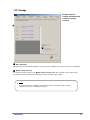
1.22 Storage
Storage setup tab
contains information and
settings for storage
structure.
1
2
2
1 [Drive Allocation]
Displays the list of local hard disk partitions. The list also shows available space and used space for each partition.
2
[Modify storage structure]
To re-allocate storage structure, press Modify storage structure button then restart the system. Upon restart
the storage structure box will appear, allowing you to make changes to your setting.
.
/ 0 8 E32:
To store video data on a partition, special structure of files and folders need be created.
“Allocation” is process of creating this structure.
Fury Manual
52
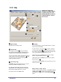
1.23 E - Map
1
22
2a
E-Map tab contains the
settings for E-Map. E-Map is
computer map of the area
with designated locations of
installed cameras, sensors
and controls
2b
3
3
4
4
5
6
7
8
1 [Check Emap]
Check the box to enable E-map.
2 [Position No.]
For a split screen mode 2a you can assign on
which channel the E-Map will be displayed (scroll
list option may vary depending on Fury Model).
You can copy E-map settings to another channel of
another split screen mode by clicking on 2b and
select the split screen mode and the channel
number you wish to copy to.
3
[User Image copy]
Click Find and select the image file to use as an Emap, then click Go! to display the image.
The DVR will automatically copy the image to its
backup folder. The backup file will be overwritten
when another E-Map image file is selected.
The image file must be in BMP format.
Fury Manual
4 [Setting]
You can mark positions of the installed cameras, controls,
and sensors on the E-Map.
To mark a device, select its type 5 (camera, control or
sensor) and its number 6 . Then select the device from
the scroll list on the right 7 and click to the location of the
device on the E-Map to insert the device’s icon.
• When device type is Camera, you can choose CCD,
Pinhole, or Speed Dome cameras in 7 .
• When device type is Control, you can choose Light or
Alarm controls in 7 .
• When device type is Sensor, you can choose Fire, Laser,
or Heat sensors in
.
7
[Delete camera, control, sensor]
To delete a device from the E-map, enable Delete camera,
control, sensor 8 and click on the device’s icon on
the E-Map. To delete all icons, disable Check Emap 1
option
.
53
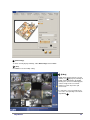
5
5
6 6
5 [Delete image]
To delete currently displayed E-Map, enable Delete image and click Save.
6 [Save]
Click Save to save the E-Map setting.
7 [E-Map]
E-Map will be displayed on the selected
channel (see 2 on page 52). Clicking on
E-Map channel will zoom in the E-Map.
Clicking on a camera icon will display the
camera’s image in full screen. Click
anywhere to return to previous split
screen mode.
If a control or a sensor is activated, you
can see the corresponding icon on the Emap blinking 8
7
8
Fury Manual
54
Chapter 2. Operation
Surveillance Mode
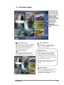
2.1 Surveillance Mode
3
4
1 [Selecting Split screen]
Select the split screen mode here. Available
modes are 4-channel, 6-channel, 9-channel,
10-channel, 13-channel, 16-channel. 33channel and 36-channel split modes are
available only in 32-ch. models.
2 [Full screen mode]
Clicking this icon switches the view to full
screen. Right clicking anywhere on the
screen will bring you back to normal mode.
Surveillance mode
is the main screen
where you can view
cameras output as
well as perform
additional functions
1 such as controlling
PAN/TILT and
ZOOM cameras,
2
and viewing
channels in
different splitscreen
mode.
[Channel Rotation]
3
Displays all channels in sequence of 4
channels at a time (see 13 in page 23 for
settings for this mode).
[Maximizing 1ch]
On any split screen mode, left clicking on a
channel view brings it to single-channel
mode. If the channel is connected with an
audio input, you can listen to live audio then.
Click anywhere on the single-channel view to
go back to split screen mode
Right-click on single-channel view to zoom-in
and zoom-out (up to 7 zoom levels are
available)
4
[Object Watch]
You can perform Object Watch function (See
page 22 for Object Watch function).
The button’s color changes to yellow when
object changes are detected
Fury Manual
55
7
5
9
10
6
11
3
12
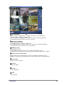
5 [Recording Mode]
8
Displays camera recording mode (see 1.14 page 26 for how to set recording mode):
Red “Rec” indicates continuous recording mode.
Blue “Rec” indicates recording by motion, sensor, alarm or any scheduled combination.
No mark indicates that the camera is not set to record video.
6 [Audio Recording Mode]
Displays audio recording status:
Red “AUDIO” indicates continuous recording mode.
Blue “AUDIO” indicates recording by motion, sensor, alarm or any scheduled combination.
No mark indicates that the camera is not set to record audio.
7 [PAN/TILT Status]
Displays PAN/TILT status.
Green “PAN/TILT” indicates that the channel is connected to PAN/TILT camera.
Red “Motion Tracking” at the top of the screen indicates that motion tracking function is enabled.
8 [Camera, Sensor, Control Status]
Displays activity status of installed Cameras, Sensors, and Controls. Activated devices are
highlighted. A control can be manually turned on and off by clicking on the corresponding button
9 [Date & Time]
Displays current date and time.
10 [Search]
Go to Search Mode.
11 [Setup]
Access Setup Mode.
12 [Quit]
Turn of the DVR.
Fury Manual
56
2.2 PAN/TILT mode
1 Left-clicking on a channel
with PAN/TILT camera will
switch to single-channel view
and the PAN/TILT menu will
appear on the right.
1
2 Click exit to return to
surveillance mode.
2
!
PAN/TILT menu may vary depending on camera model.
Fury Manual
57
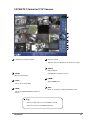
2.3 PAN/TILT Control for P/T/Z Cameras
F
M
J
L
K
G
H
I
F
It indicates present date and time.
J
PAN/TILT control
Adjust the camera’s direction to up, down, left, or right.
K
G
Adjusts FOCUS
(not applicable to Auto Focus Lens)
[WIPER]
Operate camera wiper.
H
[FOCUS]
L
[LIGHT]
[ZOOM]
Adjust ZOOM in/out.
Turn on or off camera light.
I
M
[TOUR]
Turn on or off AUTO PAN/TILT function of
camera.
.
[EXIT]
Switch to surveillance mode from PAN/TILT mode.
[Tip]
• You need a RX receiver for each PAN/TILT camera.
• Some RX receivers need additional interface.
Fury Manual
58
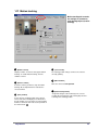
2.5 Live Audio
You can listen to live audio on
one channel if the channel is
connected with an audio input.
• Click on the channel
connected with a microphone.
A window with volume level
bar appear.
• Adjust volume or select
[Mute] if you do not wish to
listen to live audio.
Fury Manual
61
Chapter 2. Operation
Search Mode
2.6 Entering into Search Mode
Search Mode
Click Search in Surveillance Mode to
enter Search Mode.
Enter password and click Ok. By default the
password is empty (not set)
Press
1 to exit Search mode.
1
Fury Manual
63
2.7 Search by Date & Time
Pressing
will close the multi
camera panel.
Pressing
will open the multi
camera panel.
To search over the recorded data, select the date
from calendar panel.
Year & Month
Day
Time
[Daylight Saving Time]
If Daylight Saving Time is active, the timeline’s color is pink.
If Daylight Saving Time is inactive, the color is yellow.
Fury Manual
64
2.8 Intelli Search
2
1
4
5
3
6
1 [Scroll bar]
Scroll to see the list of available cameras.
/
6
[Split screen setup]
Select split screen mode for playing back here.
:
2 Camera list
Click on cameras you wish to select. Selected
cameras are highlighted.
[Split screen mode]
4 Channels - Cam 1 ~ 4
4 Channels - Cam 5 ~ 8
4 Channels - Cam 9 ~ 12
4 Channels - Cam 13 ~ 16
3 [Timeline]
Timeline displays daytime in hourly basis. Clicking
anywhere on it will change time scale (available: 1hour, 30-minutes and 10-minutes per division).
4 [Recording bars]
Each camera has a recording bar, showing when and
how the camera has recorded.
• Pink bar indicates Continuous Recording.
• Blue bar indicates Motion Recording.
• Red bar indicates Sensor Recording.
• Green bar indicates Pre Alarm Recording.
• No bar indicates that nothing was recorded.
5 [Search line]
Search line indicates current position of the
recording. The bar can be dragged left and right by
mouse to search over the recorded data.
Fury Manual
9 Channels
16 Channels
[Split screen mode (Version Dependent]
4 CH
6 CH
9 CH
10 CH
13 CH
16 CH
Number of selected
Camera
1
1~4
1~6
1~9
1~10
1~13
1~16
N
6
O2E7 8 2& P
1 splitscreen (full)
4 splitscreen
6 splitscreen
9 splitscreen
10 splitscreen
13 splitscreen
16 splitscreen
The DVR will display nothing if there is no recording at the
selected time and camera.
65
7 8
9 10
7 [Panorama]
10 [Update Graph]
Panorama displays consecutive frames from
one selected camera in 4-window split screen
mode.
Click here to update the recording bars. It is useful in
case new data are recorded while you are searching.
8 [Zoom]
Clicking Zoom will zoom the selected channel.
This function only works for channels with
resolution less than 640 X 480.
9 [Digital Zoom]
You can choose mouse mode here. Mouse can be
used to zoom in, out, or move the screen image. To
use Digital Zoom, you must have one channel selected.
There are 13 zoom levels.
!
• Zooming in and out is only available to one
channel at a time, and therefore zooming
multiple channels is not possible. In splitscreen
mode, select a channel you wish to zoom.
[Zoom In]
When you select [Zoom In], the cursor will change
into a plus sign. You can zoom in by right clicking
on a frame.
[Zoom Out]
When you select [Zoom Out], the cursor will
change into a minus sign. You can zoom out by
right clicking on a frame.
[Move]
When you select [Move], the cursor will change
into a hand. You can move the screen by holding
the right mouse button and dragging on a frame.
Fury Manual
66
11 12 13
14 15
16
17
11 [Print]
Print the selected frame. It is recommended that
you print after adjusting size and brightness.
You can only print one frame from one channel
at a time.
15 [Recording while searching]
Playback performance in Search mode will increase
when the DVR is not recording. To disable or enable
recording while searching, click [Recording while
searching].
16 [Skip]
12 [Data Backup]
Q1RO1S31,T6EPE
9U4 VVV1 1 2WE
1=
X3@
13 [Bookmark]
Bookmark the location of selected frame.
Bookmarking allows you to jump to the saved
date & time (see page 89).
1
30
Skips number of frames assigned in Skip bar when
playing back. This increases play rate and may be useful
when searching over a long period of time.
17 [Delay]
14 [Audio Play]
Playback recorded sound. You can control
volume using ‘Volume Setup’ (see page 86).
Fury Manual
Displays each frame for longer periods of time. This
function may be useful when examining a short recording
carefully.
67
2.9 Image control
[Gamma correction]
[Brightness]
Adjust brightness of the displayed frame.
Adjust balance between brightness and contrast of the displayed
frame. This function may be useful if the color of the frame looks
abnormal.
[Contrast]
Adjust contrast of the displayed frame.
[Blur & Focus]
Blur or focus the displayed frame. This function
may be useful if the frame is too blurred or too
sharp.
[Rotation]
Rotate the displayed frame 90 Y , 180 Y , 270 Y , flip horizontally,
and/or vertically.
[Restore Default]
Restore the displayed frame’s original parameters.
[Noise Reduction]
Reduce noise in the displayed frame. This
function may be useful if the frame is too distorted.
[Transform]
!
All the image-adjusting functions are only available
to one frame from one channel at a time. When in
splitscreen mode, click on a channel view you wish
to adjust.
Flatten and rotate the displayed frame for better
view if the camera was recording in tilted angle.
Fury Manual
68
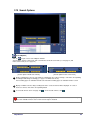
2.10 Search Options
[Search Options]
Click on
to open or close Search Options window.
Search options vary by search mode. Two search modes are Intelli search mode (see 2.8 page 77) and
index search mode (see 2.11 page 82).
2
3
2
1
3
1
[Search option in Intelli Search mode]
[Search option in Index search mode]
1 Shows recording types you can search. When recording type for a camera changes, color of the corresponding
recording bar will change accordingly (see page 77 for what colors mean)
Four recording types are available for Intelli search and two recording types are available for Index search.
2 Displays available cameras. Only recording bars for the selected cameras will be displayed. To select or
deselect a camera, click on the corresponding button.
3 To select all cameras of one category, click
!
. To deselect all cameras, click
.
Index Search will not display any data recorded in Fury System versions 4.030 and below, and will only
become available 24 hours after version 4.030 or higher is installed.
Fury Manual
69
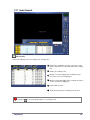
2.11 Index Search
19
[Index Search]
Index Search displays a list of recording events sorted by time.
1 Indicates the starting time for index search. The search
1
2
33
4
4
55
6 6
will be conducted over 1-minute interval from the starting
time.
2 Number of recording events.
3 Displays sensor that triggered the recording event (if
the event is of sensor recording type).
4 Displays camera that triggered the recording event (if the
event is of motion recording type)
5 Camera that recorded.
6 Shows the time when the recording event occurred.
!
When in Index Search, Search Options window will appear automatically. You can close or open it by
clicking on
. For search options details see 2.10 on page 69.
Fury Manual
70
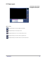
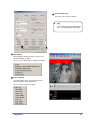
2.12 Object search
This function is used to find out
when and which objects appear
or disappear in a selected area.
[Object Search]
Clicking this button you can go to the Object Search Mode.
Clicking this button you can start object search.
Clicking this button you can see the result of the object search.
Clicking this button you can add or remove the grid from view.
Clicking this button you can add or remove the search area from view.
Fury Manual
71
3
2
2
2
3
1
11
1 [Select Camera]
Select the camera to search. The object search is possible only for one channel at a time.
2 [Set Area]
Set the area for object search. Left clicking selects a cell on the grid and right clicking deselect it.
If you did not set the search area,
the following message appears
requesting you to set the search
area.
C2 2003/06/16-12:22:00-1
3 [Set Time]
Using the scroll bar or keyboard, enter the starting time and
the ending time of the search period.
You can also use the search bar on timeline to set the starting time.
Fury Manual
72
7
6
7
6
C2 2003/06/16-12:22:00-1
4
5
5
4
4
[Start Object Search]
Clicking
button, you can start to search. A progress status 5 is displayed while the data are
extracted. Click the Cancel button on the progress status window to stop searching. You can still view
the images up to the point where the search was stopped.
6
[Object Search Result]
After images with object changes are detected, the search results will be displayed on Object Search
window. Click on the “Text” button 7 to change the way the search results are shown: text-only or
text-and-image.
Select one result from the Object Search Result window, and click on the Play button to start playing
back from the selected time.
Click on the Text button to view
the results in text-only mode.
.
[Image Mode Display]
Click on the Image button to view
the results in text-and-image mode.
[Text Mode Display]
[Tips]
If the object disappears and there is no motion for more than 3 seconds after the object disappears, it will be
detected by the object search. In the same way, if the object appears and there is no motion for more than
3 seconds, it will be detected by the object search as well.
Fury Manual
73
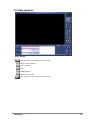
2.13 Video playback
Playback button
Move to the first recorded data of the selected date
Play one frame backward
Reverse playback
Stop
Forward playback
Play one frame forward
Move to the last recorded data of the selected date
Fury Manual
74
2.14 Audio Playback
Z
1
1
1
/ 6 V8 E7 19,S
1,T[:
N
If you select any single channel which has saved audio data, you can
replay audio with the recorded image.
(You can not replay audio data with the multi-channel search mode.)
Click
and the “VOLUME” window appears as shown left.
If you do not wish to listen to the saved audio, check
Mute.
You can adjust volume by scrolling up or down with the mouse.
.
[Tips]
• Audio synchronization takes roughly 1 to 3 seconds to initialize and may result in some
video loss. This procedure is normal.
• Audio is supported only for forward playback. Audio play is not supported for other
search - backward playback, frame by frame search, etc.
• When audio is playing, Skip and Delay functions will not work.
• For audio configuration, refer to Appendix D.
Fury Manual
75
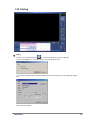
2.15 Printing
1
1
1
[Print]
To print, select a channel and click
. It is recommended that you print after adjusting
frame size and brightness. You can print only one channel image at a time.
If you wish to have Watermark or Frame information printed on the image, check the appropriate option
box.
Click on OK to start print.
Fury Manual
76
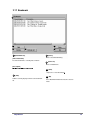
2.16 FullFull-screen mode
\ ] ^ _ ] ] ` a ] b a ^ b c ^ ^ d ` e d ] ^ c ^ ^^^
\ ] _ _ ] ] ` a ] b a ^ b c ^ ^ d ` e d ] ^ c ^ ^^^
\ ] ` _ ] ] ` a ] b a ^ b c ^ ^ d ` e d ] ^ c ^ ^^^
\ ] f _ ] ] ` a ] b a ^ b c ^ ^ d ` e d ] ^ c ^ ^^^
\ ] g _ ] ] ` a ] b a ^ b c ^ ^ d ` e d ] ^ c ^ ^^^
\ ] b _ ] ] ` a ] b a ^ b c ^ ^ d ` e d ] ^ c ^ ^^^
\ ] h _ ] ] ` a ] b a ^ b c ^ ^ d ` e d ] ^ c ^ ^^^
\ ] e _ ] ] ` a ] b a ^ b c ^ ^ d ` e d ] ^ c ^ ^^^
\ ] i _ ] ] ` a ] b a ^ b c ^ ^ d ` e d ] ^ c ^ ^^^
\ ^ ] _ ] ] ` a ] b a ^ b c ^ ^ d ` e d ] ^ c ^ ^^^
\ ^ ^ _ ] ] ` a ] b a ^ b c ^ ^ d ` e d ] ^ c ^ ^^^
\ ^ _ _ ] ] ` a ] b a ^ b c ^ ^ d ` e d ] ^ c ^ ^^^
\ ^ ` _ ] ] ` a ] b a ^ b c ^ ^ d ` e d ] ^ c ^ ^^^
\ ^ f _ ] ] ` a ] b a ^ b c ^ ^ d ` e d ] ^ c ^ ^^^
\ ^ g _ ] ] ` a ] b a ^ b c ^ ^ d ` e d ] ^ c ^ ^^^
\ ^ b _ ] ] ` a ] b a ^ b c ^ ^ d ` e d ] ^ c ^ ^^^
Fury Manual
77
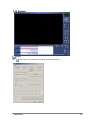
2.17 Bookmark
1
2
5
3
4
1 [Bookmark List]
[Time information]
List of the bookmarks, sorted by date and time.
6
3 [Delete]
Delete selected bookmark(s).
4 [Delete all]
Delete all bookmarks.
[Description]
j 8 2E7 19&2kV2&l8 E
m8 41S
T < 1lT
5 [Goto]
Jump to the selected bookmark
2 [Add]
Add the currently displayed frame to the bookmark
list
Fury Manual
@
6 [Ok]
Close Bookmark window and return to Search
mode.
78
2.18 Backup
[Backup]
Click
to backup the recorded data. Backup window shown below will appear.
Fury Manual
79
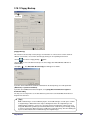
2.18.1 Floppy Backup
1
2
3
[Floppy Backup ]
This function used to backup a frame (image), not video data. It is a must to have a frame zoomed:
-When in search mode, select a frame to backup by clicking on corresponding channel view
-Click on
and choose “Floppy backup”
1 option
-Click on 2 to select a medium to backup to. It can be floppy disk, HDD, CD-RW, USB-flash or
network driver
-Click [OK]
3 . The “Watermark Checker Copy” box will appear as follows:
If you wish to have Watermark and Frame information on the backup image, check the option box
[Watermark] and [Frame information].
If you wish to install Watermark Check Program, check [Copy Watermark Checker Program to
destination folder].
You may save as many frames as the disk allows but you do not need to install Watermark Checker
Program more than once.
.
[Tips]
BMP or JPEG images can be modified by anyone, and modified images can look just as realistic
as original images. Watermark feature helps to distinguish between the original images and
modified images. When the system saves an image onto its hard disk drive, it will encode each
image with Watermark (provided you have Watermark feature enabled in System Setting) leaving
a ‘mark’ on each image. When an image is modified, the ‘mark” will change, therefore allowing the
System to differentiate between modified images and original images.
Fury Manual
80
[Watermark Checker]
To run Watermark Check program, double-click ‘WMChecker.exe’ on the backup medium. The
following window will appear.
To check an image, click [File Open] and open the image you wish to check.
Fury Manual
81
Click [Water Mark Check] to verify the image.
After verification is completed, the results will be displayed as shown below
Corrupt (modified) image
Fury Manual
Approved (authentic) image.
82
2.18.2 Time backup
This function is used to backup video data in
Fury video format. Fury’s Site program is needed
to playback them.
1
2
4
5
3
1
[Time backup]
[Backup Media]
4
Select this backup mode when you need to backup
Select a medium to backup to.
video data in Fury format.
You can select HDD, CD-RW, Portable drive, Network
Drive, Remote IP Address.
2 [Date/Time]
Select the start and the end time of backup data.
Date and time has to be set before your current time. In
other words, you can’t backup video data “in future”.
3
[Calculate size]
5
[Format CDR/CDRW]
This option is used when you select a CD as a backup
medium.
If a CD has not been formatted, you can format a CD using
Direct CD program or InCD program. To do so, press
[Format CDR/CDRW] button.
If you want to check data size for the selected backup
press ‘Calculate Size’ button.
.
/ 0 8 E32:
Time backup requires a large amount of free
space, as one minute backup usually requires
66 megabytes of free space.
To format a CD, Direct CD program or InCD
program have to be installed beforehand.
(When formatting a CD using InCD program,
only CD-RW media is supported.)
Fury Manual
83
6 [Option]
[Delete old data when free space insufficient]
This option will delete any old data on the selected
medium when there is not enough storage space for
backup.
7 [Priority]
Set backup’s priority when other backups are scheduled.
Setting the option to Backup after precedent backup will
place the backup in queue. Backup after current backup
will ignore the queue.
6
7
8 [OK]
Press [OK] to start backing up.
8
.
/ 0 8 E32:
Time backup will backup video data from all cameras. It is not possible
to select cameras for this backup mode.
Fury Manual
84
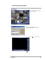
2.18.3 AVI backup
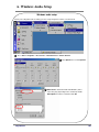
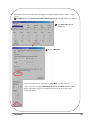
This function is used to backup video
data in one of the standard MS
Windows Media Player formats.
1
2
3
4
1 [AVI backup]
[Format CDR/CDRW]
Select this backup mode when you need to backup
This option is used when you select a CD as a backup
medium.
video data in MS Windows AVI format. Audio data
can be backed up alongside with video data.
2
[Date/Time]
Select the start and the end time of backup data.
Date and time has to be set before your current
time. In other words, you can’t backup data “in
future”
3
If a CD has not been formatted, you can format a CD
using Direct CD program or InCD program. To do so,
press [Format CDR/CDRW] button.
[Backup media]
.
/ 0 8 E32:
To format a CD, Direct CD program or InCD
program have to be installed beforehand. (When
formatting a CD using InCD program, only CDRW media is supported.)
Select a medium to backup to.
You can select HDD, CD-RW, portable drive,
network drive, remote IP address.
Fury Manual
4 [Split by]
When creating a backup in AVI format, you can split
the resulted file by time or size.
85
5
5
[Camera]
Select the camera number to create the AVI backup.
For AVI backup, it is not necessarily to select all cameras like in Time Backup. Selection one or few
cameras to backup from is possible.
Fury Manual
86
6 [Select Compressor]
Select the codec for the AVI backup.
.
[Tip]
You can not backup audio data that have
been recorded through the audio board.
J
K
L
7 [AVI Caption]
When playing the backup AVI video, you can select
caption information to display.
You can select 6 different types of caption information.
8 [Select Position]
This option allows you to select the position of the
caption information for the AVI backup.
You can select from 9 different option.
Fury Manual
87
2.18.4 E-Mail backup
The e-mail backup function is used to
1
send the backup to designated e-mail
account(s). E-Mail backup can backup 1
minute video data in MPEG format or a
single frame (image) in JPEG format.
5
2
3
4
1 [E-mail Backup]
Select this backup mode when you need to send
5 [Mail Setting]
[Recipients List] shows the list of registered e-mail
backup video data by e-mail
accounts.
[Add] is to add an e-mail account to the receiver list.
2 [Date/Time]
Select the starting time to backup the data.
The starting time must be earlier than the current
time. In other words, you can’t backup data “in future”
3 [Still Image Backup]
Backup the current displayed frame in JPEG format.
This option is available only when a single frame is
displayed.
[Delete] is to delete an e-mail account from the list.
4 [AVI Backup]
Select this option to backup one-minute video data
(starting time is specified in 2
) in AVI format.
In the [Mail Server] field, enter the outgoing mail
server (SMTP) address.
In the [Sender] field, enter the sender’s e-mail
account.
In the [Mail Subject] field, enter the mail subject.
Fury Manual
88
2.18.5 Common backup options
1
2
3
4
1
[Backup Media]
4
[Priority]
Click [Select media] to change media used for backup. Priority is only needed for backup schedule (see page 42).
The DVR can use following media:
• Hard Disk Drive
• CD-ROM
• Portable Drive
• Network Drive
• Remote IP Address
2
[InCD Eject]
InCD is a program developed by Ahead Software
which formats CD-R and CD-RW . Clicking [InCD
Eject] will eject CD-ROM drive.
3
[Format CDR/CD-RW]
When choosing CD-ROM as media, you have the option of
formatting CDs. Formatting CD-R will delete any data stored in
CD, making it reusable. Formatting CD-RW will enable Direct CD
feature, which allows you to move, delete, and copy data onto
CD in a way similar to a floppy disk.
!
In order to format CDs, you will need to purchase
Easy CD program, and is not included in default
package. Contact the local distributor to place an
order.
You may also purchase a similar product called Nero.
[Options]
[Delete old data when free space is insufficient]
If there’s not enough space to create a backup, the
system will automatically delete old data in the backup
medium in order to create enough free space.
Fury Manual
89
Appendices
•
•
•
•
A. Backup Files
B. Receiver Boards Layout
C. User Management
D. Windows Audio Setup
A. Backup Files
All essential files needed to set up Fury System are stored in C:\BackUp-Win2K. In case of
serious computer breakdown or if system setup files are required for other reasons, use the
backup files stored in this folder.
We do not recommend inexperienced computer users to use, move, or modify backup files
unless otherwise instructed. Do not delete any backup files under any circumstances, as
this may cause serious problems to the system. Only handle backup files if you are an
advanced user.
The following figure tree shows the backup files contained in C:\BackUp-Win2K (folder
structure many vary).
Backup Files
Drivers
Audio Driver
Motherboard Drivers
Chipset Patch
Intel Application
Accelerator
Card Drivers
Fury
Fury
Fury
Fury
Network Drivers
Modem Drivers
LAN Drivers
VGA Drivers
Windows Add-On
Windows Media Player Codec
DirectX 8.1 - NT
Programs
Software Program
Center Program
Windows 2000 Professional
Fury Manual
Windows-related drivers & software
91
B. Fury Receiver Board Layouts
B.1. RX-Receiver (KRE-301) layout (optional)
Inside of RX-Receiver
P/TILT ADDRESS Pointer
o?p ;j
Control board FUSE
110V/220V conversion SWITCH
TX LED
Main fuse
RX LED
COMM
ZOOM
FOCUS
LEFT
RIGHT
DOWN
AUX
UP
220 110 24V
CAMERA
LIGHT
WIPER
AC INPUT
+
n
422 signal
AC input
LENS signal
(for DC 12V only )
Light control output
PAN/TILT signal
Common 24, 110 , 220 : AC
P/T, Wiper, Camera, AUX
Power signal
Light-type controls voltage is same with AC input voltage. The voltage for Camera LENS signal is set
to DC 12V.
Fury Manual
92
B.2. RX-Receiver (KRE-302) layout (optional)
qsrutvqxwyzw{3|w}
Inside of RX-Receiver
1. COM 1 : TRANS connection site
2. COM, 24V, 110V, 220V : TRANS connection site
3. AC 220V/110V : Select AC input voltage
4. FUSE : 250V/1A (control FUSE : RX Receiver control Fuse)
5. FUSE : 250V/2A (RX Receiver voltage Fuse)
6. MAIN INPUT : main input voltage
7. LIGHT : output of AC input voltage (connect to lamp power)
8. COMMON : 220 , 110, 24V : AC output voltage (can be used commonly)
9. CONTROL : WIPER, CAMERA, AUX : connect to each connectors’ power
10. RIGHT, LEFT, DOWN, UP : connect to PAN/TILT DRIVE
11. ZOOM, COMM, FOCUS : connect to Lens
12. +, - : connect to RS-422 signal line on BOARD (IO8816)
13. PWR : Power display LED for RX Receiver
14. TXD LED : LED displaying data transmission from RX-Receiver to IO8816(RS-422)
15. RXD LED : LED displaying data transmission from IO8816(RS-422) to RX-Receiver
16. PAN/TILT ADDRESS : Assign address when using multiple RX-Receivers (assign from 00 to 99)
Fury Manual
93
C. User Management
User management
In order to connect Site with Center for Emergency Connections, User Management needs to
be set up correctly beforehand.
User password and account for Guest must be set up for modem connections. To do so, follow
the steps shown below:
1
Double-click on Users and Passwords in Control Panel (To access Control Panel: Press Start
Settings
Control Panel).
2
Select Advanced tab and click Advanced
button.
3
Fury Manual
Select Users menu and right-click on
Guest to select Properties.
94
4 Enable Guest account by disabling Account
is disabled option and click Ok.
5 Select Users menu and right-click on
Guest to select Set Password.
6 Type 1234 for both New password and
Confirm password (Default password for
Center is set to 1234).
7 Click Ok when confirmation message appears.
Fury Manual
95
Setting PPP for PSTN/ISDN
1
[Requirements]
• During the installation, the system may ask you to
insert Windows 2000 Professional CD. In these cases,
simply type the location of Windows 2000 Professional
backup folder.
• Before proceeding with PPP setup, you must have a
modem installed in Windows (if a physical modem is
not installed to system hardware, PPP setup is not
required at all). To install a modem, find the correct
modem driver from the backup folder and install the
driver.
• Close any Network or dial-up server properties
window before installing.
2
[PPP Setup using KPPPSetup.exe]
3
[Install Components]
Launching KPPPSetup.exe will install following
components:
• Dial-Up Networking
• Dial-Up Server
• Changes made to Dial-Up Server properties
• Phone dialer
• TCP/IP Protocol
! • If TCP/IP or Dial-Up adapter is already installed,
they will not be installed again.
• Do not run KPPPSetup.exe more than once in
same instance. Wait until a message indicating
that your system will reboot appears.
KPPPSetup.exe installs and makes changes to
network components automatically. Double-click
KPPPSetup.exe as shown above. PPP setup for PSTN
and ISDN will also complete automatically. Repeat the
procedure for Center PC.
After installation is complete, please check to see if
connection between Site and Center PC works correctly
using Site and Center software.
Fury Manual
96
Creating Network Icon
• Please make sure a modem for PSTN and/or ISDN TA (Terminal Adapter) is installed properly before
proceeding.
• There is no automatic PPP setup file for Dial-Up Networking setting. It must be done manually as shown
below:
1 Double-click on Network and Dial-up Connections in Control Panel (To access Control Panel: Press Start
Settings
2
Control Panel).
Double-click on Make New Connections to begin Network Connection Wizard and proceed by clicking Next.
3 Select Dial-up to private network
and click Next.
4 Leave all boxes empty as shown and
click Next.
Fury Manual
97
5 Select Create this connection: For all users in Connection Availability and click Next.
6
7
Fury Manual
Type Network for the name of
connection and complete Network
Connection Wizard by clicking
Finish.
Connect Network window will appear automatically.
Delete any name in User name and click Properties.
98
8 Select Options tab and change the Dialing
options as shown. Click Ok.
9
Leave Dial box blank and click Cancel.
10 Check if Network icon is created in Network and Dial-up Connections (follow Step 1 to access Network
and Dial-up Connections).
Fury Manual
99
Creating Incoming Connections icon
1
Double-click on Network and Dial-up Connections in Control Panel (To access Control Panel: Press Start
Settings
Control Panel).
2
Double-click on Make New Connections to begin Network Connection Wizard and proceed by clicking Next.
Fury Manual
3
Select Accept incoming
connections and click Next.
4
For Connection devices, select the
modem you have installed and click
Next (the modem installed may
differ to the screenshot shown).
100
5 Select Do not allow virtual
private connections and click
Next.
6 For Users allowed to connect,
select Guest from the list and click
Next.
Fury Manual
101
7 Do not make any changes in
Networking software setting
and click Next.
8 Complete Network
Connection Wizard by
clicking Finish.
9
Check if Incoming Connections icon is created in Network and Dial-up Connections (follow Step 1 to
access Network and Dial-up Connections).
Fury Manual
102
Connection properties
1
Double-click on Network and Dial-up Connections in Control Panel (To access Control Panel: Press Start
Settings
Control Panel).
2
Right-click on Income Connections and select Properties.
3
Fury Manual
In General tab, select a modem device and click
Properties.
103
4 Select Users tab and enable Guest from the
list (in some cases, if Guest is disabled, Dialup Networking will not work properly).
5 Select Networking tab. Then select Internet
Protocol (TPC/IP) and click Properties.
Fury Manual
104
6 Change the setting as shown below and click Ok.
Network access: enable Allow callers to access my local area network.
TCP/IP address assignment: select Specify TCP/IP addresses and type the below address.
• From: 192 . 168 . 55 . 1
• To:
255 . 255 . 255 . 0
This concludes network setup.
Fury Manual
105
A. Windows Audio Setup
Windows audio setup
Before proceeding with audio recording, you must setup microphone volume as shown below:
1
Press Start
Programs
Accessories
Entertainment
Volume Control.
2 Click Options and select Properties.
3
Fury Manual
Mixer device should be installed to Windows (device
name may vary depending on the soundcard). Enable
Microphone for volume control and click OK.
106
If microphone input level is too low, you can amplify the microphone input to increase volume as shown
below.
1 Click Options and select Advanced Controls (if Advanced Controls is already enabled, do not click it).
2 Click Advanced button for
Microphone.
1
2
3
Enable 1 Mic Boost.
If you do not wish to hear recorded voice, enable Mute as shown on the left.
If the system does not support Microphone boost function, Advanced button will not
appear. If you need to increase the microphone input level, you must acquire more
sensitive microphone.
Fury Manual
107
Index
F
A
Alarm
Audio
Audio recording status
Audio playback
Auto - PAN/TILT control
AVI backup
21, 23
37
61
75
58, 59
85
91
42, 92
44
78
Camera flip
49
Cameras
16
Card drivers
91
CD - R/RW – backup
83, 85
Common backup options
96
Communication conversion cable 6
Connection properties
103
Continuous recording
26
Control
14
74
65
21
6
Fury Manual
I
Image control
InCD – backup
Incoming connections
Index search
ISDN
68
83, 85
100
70
11
L
LAN
Leased circuit
E
Easy Update
E-Map setup
Emergency Message
Emergency IP address
Emergency phone numbers
16
28
K
D
Data playback
Daylight saving time
Detection Area
Drivers
59
H
Hardware setup
Holiday
C
80
7
77
G
Go-to - PAN/TILT
B
Backup files
Backup
Backup media
Bookmark
Floppy backup
Front view
Full screen
31
11
47
52
31
31
31
108
M
Microphone
Modem setup
Motherboard drivers
Motion recording
Motion setup
Motion tracking setup
S
37
30
6
26
21
49
N
NC, NO
Network drivers
Network
18
6
97
P
Schedule setup
Screen division
Screen size
Secure Channel
Sensitivity
Sensor
Sensor recording
Setup mode
Site code
Site information
Split screen
Storage setup
System setup
26
29
24
23
21, 51
19
26
15
30, 33
33
29, 65
48
39
T
Package contents
PAN/TILT
Panorama
Password setup
Playback
PPP
Pre-Alarm recording
Print
Programs
PSTN
6
57
66
18, 47
74
96
26
76
6
11
Time backup
Timeline - Search mode
Transfer quality
83
64, 65
25
U
User management
94
V
R
Rear Side
Record Mode
Recording frame rate
Recording status
Rotation
RX-Receiver
8
26
24
69
23, 28, 43, 55
92, 93
VGA drivers
Video loss alarm
6
40
W
Warranty Guide
110
Watermark
39
Windows 2000 Professional files 6
Windows add-on
6
Z
Zoom
Fury Manual
70, 71, 72
109
Warranty Guide
This product has passed quality control tests. If the system breaks down in its own during
normal usage we provide 12 months warranty service.
Warranty Guide
Check the Product Warranty Service below first.
Please contact the distributor when there is problem with the product and inform the
engineer what the problem is.
Standard procedures for repairing, replacement or refund will follow.
Warranty Content
For any defects found while normal usage within warranty service period, we will provide free repair
service.
We charge fees for parts and services if the defect was caused by:
1. Carelessness handling.
2. Natural disaster.
3. Disobeying instructions in product manual.
4. Incorrect power voltage or frequency.
5. When you want to reassemble for full system or replace parts within warranty service period.
6. Unauthorized engineer modifying or causing damage to product during repair.
We charge fees for any repairs after warranty period.
Product Warranty Service
Product & model name
Product Serial Number
Distributor
Date you purchased
Warranty Period
Customer
12 months from purchase date
Name
Address
• This warranty sheet will not be provided again unless exceptional cases.
• Please fill in the blanks after you purchase the product.
• You must show this product warranty service sheet to receive warranty service.
If you have any questions about this
product, you may call:
Kaltech Enterprises Tech Support Center
1-866-446-3595 Ext. 242
[email protected]