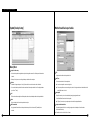
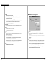
Download SPR Smart Viewer Use..

Transcript
Before installation Begins
What is SPR Smart Viewer Program?
SPR Smart Viewer Software program enables you to detect from remote site without
having to go to the place where DNE(SPR Smart View System) is installed.
Outline of System (Recommendation)
CPU
: Celeron 433MHz or more
MEMORY : 64MB or more
VGA CARD : AGP 16MB or more
HDD
: enough space to hold more than 100MB
O/S
: Windows98 SE / Windows ME / Windows 2000 / Windows XP
Communication line : LAN, MODEM, ISDN, exclusive line
DirectX
: V7.0 or higher
Product Must Include...
Table of Contents
5
I. SPR Smart View er Operation
7
1. SPR Smart Viewer program setup
2. Execute SPR Smart Viewer program
3. Main Screen
4. Communication Environment Setup
5. Communication Connection Viewer
6. Call Current Image
7. Communication Disconnection Viewer
10
11
12
17
Below items must be included with SPR Smart Viewer program.
30
31
33
35
36
37
SPR Smart Viewer Program
User Manual
38
41
42
53
55
56
58
59
61
63
69
80
84
87
II. Search Mode
1. Run Search Program
2. Search Date and Time Selection
3. Camera Selection
4. Playing Recording
5. Search Tool
6. Data Backup
7. Print Search Screen
8. Pan/Tilt Mode
9. Search Backup Data
10. Audio Replay
11. 2Way Audio
III. Remote View(DNE) Setup
1. Hardware
2. System
3. Recording Schedule
4. Motion Detection
IV. Remote Backup Server
88
1. Remote Backup Server
93
V. Intelli Upgrader
94
99
100
102
107
1. Intelli Upgrader
VI. Health Monitor
1. Health Monitor
2. Tool bar
3. Tab
113
114
115
117
118
120
121
122
126
131
135
138
VII. Emergency Monitor
1. Emergency Monitor
2. Tool Bar
VIII. Web DV R
1. Accessing WebDVR
2. Function of WebDVR
IX. Appendix
1. Installing Center PPP in Windows98
2. Installing Center PPP in Windows 2000/XP
3. Formatting CD Using Direct CD
4. Formatting CD Using InCD
5. System Setup for Audio Function
I
Operate
SPR Smart View er
5
I. Operate SPR Smart Viewer
1
SPR Smart View er
Program Setup
1. Insert SPR Smart Viewer program CD into CD-ROM and click on folder where program is stored,
then window below will appear. Double click on ‘Data1’ folder.
2. Double click on Setup.exe file.
3. Select [Next].
7
I. Operate SPR Smart Viewer
4. Select ‘I accept this License Agreement..’ and then click [Next].
7. Select [Finish] after program is installed.
5. When “Select installation folder” window appears, browse or select installation folder and
click [Next].
8. SPR Smart Viewer icons will be created on the desktop.
Double click on SPR Smart Viewer icon to execute program.
6. It will starts to process and copy Program file.
8
9
I. Operate SPR Smart Viewer
2
E xecute SPR Smart
V iew er Progra m
3
Main Screen
1. Double click on SPR Smart Viewer icon from the desktop and execute program.
2. Start SPR Smart Viewer and check the password.
Password is not setup initially so click [OK].
Description
The present date, day, and time are displayed.
Indicates status of send/receive data between SPR Smart View and Viewer
The IP address of the connected DNE and the name of the installation place are displayed
A button to connect the SPR Smart View
A button to display are current image to connect the SPR Smart View
A button to disconnect the SPR Smart View
A button to make settings when connecting the SPR Smart View and Viewer
[Warning]
The camera number and the controller are displayed when the SPR Smart View is connected
• Password cannot be recreated so do not lose your password
A button to enter into Search mode to search the backup data and the data of the SPR Smart View
(Password should also be written separately)
• No more than one person should have the password information
Refer to page 14 for password information
10
A button to make settings to use 2-way audio feature when the SPR Smart View is connected.
A button to exit the SPR Smart Viewer program
A button to enter into 4, 9, 16-division and full screen modes.
11
I. Operate SPR Smart Viewer
Check Water-Mark Authentication
4
C o m munication
E nvironment Setup
: You may indicate Water-Mark authentication image on searched image.
▶ When button is pressed: Water-Mark authentication is indicated on the image
▶ When button is not pressed: Water-Mark authentication is not indicated on the image
Storing current image
Setup Communication Environment using the button on the left
Viewer setup’s [Setup configuration] Screen
: When transmitting current image after connection is made, the image will also be stored in hard
disk drive (assigned through Viewer) at the same time.
▶ When button is pressed: Current image is stored
▶ When button is not pressed: Current image is not stored
Storing searched image
: When searching for recorded image and connection is made to View, it will also be stored in hard
disk drive at the same time through viewer.
▶ When button is pressed: Current image is stored
▶ When button is not pressed: Current image is not stored
Select a drive to store
: When searching for current or recorded data after connection is made to View, you must select
hard disk drive which will be stored to Viewer.
☞ [Note] Recordable media
From Hard disk or window, you may store with removable drive (DVD-RAM, ZIP, MOD, ORB, USB HDD etc)
and with Network drive.
Full Screen By SmartView
: This is a function to integrate Full screen function of SmartView with SmartViewer.
▶ When button to pressed
Description
: Intergrate with Full Screen function of SmartView
▶ When button is not pressed: Do not integrate with Full Screen function of SmartView
☞ [Note] Full Screen function
DISK DRIVE
This is a function to display a full screen image of the camer of the camera or sensor that the has motion
: It has Driver information.
activity or sensor signal.
SPR Smart Viewer’s Program and system information appear.
Clock - 12 Hours or 24 Hours Mode
See manual control status bar
: Indicate status of manual control button from initial screen
: To convert clock mode - 12 Hours or 24 Hours. When 24 Hours mode is in use.
AM/PM will not be displayed.
▶ Manual control status bar button is pressed: manual status is indicated
▶ Manual control status bar button is not pressed: status is not indicated
12
13
I. Operate SPR Smart Viewer
Change Password
SPR Smart Viewer [Modem] Screen
: This function is to change password.
(Tip: The password is initially not setup)
① Enter current password and click [OK]
② Enter new password and click [OK]
Store
: Finish Setup configuration and click [Save]
Close
: It will return to Viewer’s main screen when you click on [Close]
Language
: It supports multiple language - Korean, English, French, Chinese, Italian, Spanish, and German
Example) Select one of the language that you want to use and click on [Save].
Description
Select Type of connection
: Select the type of communication line you wish to use.
▶ Select ‘LAN/ISDN(ROUTER)/LEASED CIRCUIT(ROUTER)’ when you are using LAN or
ISDN/Exclusive (using ROUTER).
▶ Select ‘PSTN/ISDN (NO ROUTER)’ when using general telephone line or ISDN (without ROUTER)
[Installed modem name]
: It automatically recognizes the modem installed in the system.
[Initialization string]
: It automatically recognizes initial order from windows installed to the system
14
15
I. Operate
I . 시SPR
스 템 Smart
개 요 Viewer
[Port and Bps]
5
C o m munication
Connection View er
: It automatically recognizes communication port and speed of modem installed to the system.
Select this button on the left and connect to DNE
[Preservable connection time]
☞ Basis of LAN connection
: If time expires while phone is connected without any manipulation, it will automatically be
disconnected.
SPR Smart Viewer Screen connection
Description
Connection List
: In order to connect to DNE, select [Add] button and register following: group, View CODE, IP
Address, place to be installed, and password. That way, if you have to connect to DNE again,
then it can easily be connected to appropriate DNE from the list you made.
Add
: Add the Site(DNE) you wish to connect.
▶ Select [Add] button and assign View Code, IP address, place to install, and password, then click
[OK].
16
17
I. Operate
I . 시SPR
스 템 Smart
개 요 Viewer
Modify
: Modify DNE information which is/are already entered.
▶ Select DNR information you wish to modify and click [Modify].
▶ [Group]
: You can assign group for any View(DNE) information Entered
▶ Modify DNE information and select [OK] to store modified information.
▶ [Group Add] : Make a new group for any View(DNE) information Entered
▶ [View Code] : View Code can be added in the order of 100-001,100-002,100-003...etc.
▶ [View Name] : Enter Place of installation
▶ [IP Address] : Enter DNE’s IP address
▶ [Password]
: Enter password for DNE Menu (Network → Password) Password
▶ [Confirm]
: Enter password for DNE connection
▶ [Auto connection when starting] : When executing the Viewer, this function allows to connect
to View automatically.
[Warning]
While connecting to DNE from SPR Smart Viewer, it will autocheck the View CODE and password and if they are not correct,
connection will fail.
18
19
I. Operate
I . 시SPR
스 템 Smart
개 요 Viewer
Delete
: Delete DNE information.
▶ Screen below appears to DNE along with DNE’s camera number, Control indication
button, View IP, and Position.
▶ Select appropriate DNE and click [Delete]
Cancel
: Go back to main screen after closing Connect View LAN window.
Connect
: Connect DNE from SPR Smart Viewer.
▶ Select the DNE you wish to connect and click [Connect]
▶ It is being connected to DNE
20
21
I. Operate SPR Smart Viewer
SPR Smart View Favorites
Description
▶ [Favories name]
: To enter the name to register in the favorites list.
▶ [Added View list]
: This is a list to be registered if you select the desired View for from
‘View List’ item and the then press [<] button.
List
: This shows the Favorites list registered by the user. After selecting [Add] button, if you enter
the DNE information the ‘Name’ item from ‘Favorites Edit’ screen and save it, this will be added
▶ [View list]
: This shows the View list registered in View.
▶ [<] button
: If you select the desired ‘View’ item and the press [<] button,
to the Favorites list
Connect
the information of the selected View will be registered to ‘Added View’
: After selecting the desired item from the list, select [Connect] button. You will be connected to
item.
the DNE linked by the selected item.
▶ [>] button
: If you select the View information to delete from ‘Addde View’ item and
Add
then press [>] button, the View information will be deleted from
: This is to add the favorites name to the list.
‘Added View’ item.
▶ After selecting [Add] button and selecting the list of ‘View’ item from ‘Favorites Edit’ screen,
press [<] button to add the selected View information to ‘added View’ item.
▶ After selecting the registered View information from ‘added View’ item, select the desired
camera no. to call from ‘View camera select information’ item.
▶ After selecting the name to ‘Favorites name’ item, press [Save] button.
22
▶ [>>] button
: If you press [>>] button, all View information from ‘Added View’ item
will be deleted.
▶ [View camera select information] : When executing the Viewer, this function allows to View
automatically.
23
I. Operate SPR Smart Viewer
Delete
Save current connect
: This is to delete the registered Favories name from the list.
: If you select [Save current connect] button in the stae of connecting with DNE corrently,
▶ After selecting the desired Favorites name to delete from the list, press [delete] button.
the connected DNE information shall be registered in the Favorites list.
▶ If DNE is connected, [Save current connect] button will be active. At this time, press
[Save current connect] button.
Modify
: This is to modify the View information of the Favorites name registerd in the list.
▶ After selecting the desired Favorites name to modify from the list, press [modify] button.
▶ If “Favorites name input” screen is displayed, enter the Favorites name and click [OK] button.
▶The entered Favorites name shall be registered in the list.
▶ After modifying the Favorites information, select [Save] buton to save the contents.
24
25
I. Operate SPR Smart Viewer
From the communication enviroment tab of Viewer setting, the line type shall be selected
by “PSTN/ISDN(NO router)”
.
Select button to connect to View
SPR Smart Viewer Screen connection (PSTN)
▶ [Group]
: You can assign group for any View(DNE) information Entered
▶ [Group Add] : Make a new group for any View(DNE) information Entered
▶ [View Code] : View Code can be added in the order of 100-001,100-002,100-003...etc.
▶ [View Name] : Enter Place of installation
Description
Connection List
: To connect to View, select [Add ] button and enter Group and View code, IP, Tel no. , Installation
please, password etc. to register in the connect list. This enables you to connect to connected
▶ [TEL Address]: Enter DNE’s IP address
▶ [Password]
: Enter password for DNE Menu (Network → Password)
▶ [Confirm]
: Enter password for DNE connection
▶ [Auto connection when starting] : When executing the Viewer, this function allows to connect
to View automatically.
View easily when you try to connect to View later.
Add
[Warning]
: This adds the information of the desired View to connect.
While connecting to DNE from SPR Smart Viewer, it will auto-
▶ Select [Add] button to designate View Code, IP , Installation place , password and then select
check the View CODE and password and if they are not correct,
[OK] button.
26
connection will fail.
27
I. Operate SPR Smart Viewer
Delete
: Delete DNE information.
Modify
▶ Select appropriate DNE and click [Delete]
: Modify DNE information which is/are already entered.
▶ Select DNE information you wish to modify and click [Modify].
Cancel
: Go back to main screen after closing Connect View PSTN window.
Connect
: Connect DNE from SPR Smart Viewer.
▶ Select the DNE you wish to connect and click [Connect]
▶ Modify DNE information and select [OK] to store modified information.
▶ It is being connected to DNE
28
29
I. Operate
I . 시SPR
스 템 Smart
개 요 Viewer
6
Call Current Image
① Select camera number to be shown.
7
C o m munication
Disconnection View er
(Installed camera will not be indicated on screen)
Select this button on the left and disconnect to View.
②
Show Camera image by selecting button from DNE.
Communication disconnection on calling current image
When current image is selected
: if you select disconnection button on calling current image with connection to DVR(SPR Smart
View), the Winodws below appears.
Select [OK] button and when “Do you want disconnection?” windows appears, select [Yes] button
and disconnect with View.
Communication disconnection
If you select disconnection button only on connection to DNE not calling current image,
”Do you want disconnection?” windows appears. Select [Yes} button and disconnect with DNE.
[Note]
When
button is selected without selecting camera button, an error message below
will appear.
30
31
Ⅱ
Search Mode
33
Ⅱ . Search Mode
1
R un Search Progra m
① Click on search
button to execute from surveillance screen.
② Password screen will appear for securing purpose Click [OK] if the password was not initially
entered
Search Screen
Switch to Surveillance Mode
Search window
Calendar
Function
Button
Camera button
Scroll
Camera
Storage Capacity
Time Display &
Expansion of Graph Section
Split Screen Setting Button
Configuaton of Search Screen
▶ Search screen Window
▶ Calendar which shows recording date
▶ Time display & expansion of graph section
▶ Function button for search
▶ Switch to monitoring mode
▶ Split screen setting button
▶ Scroll and Camera button to select a camera to search
▶ Graph indicating the type of recording & storage by tme zone
35
Ⅱ. Search mode
2
Ⅱ . Search Mode
Search Date and Time Selection
Calendar
Search ‘Date’
3
C a m e ra Selection
Camera Selection Screen
: Choose the Date you wish to search
▶ << : It shows whole calendar
>> : Calendar shows the following month
▶ On calendar, it will be indicated in yellow if
anything is recorded on such date, red
indication means the one you clicked to
search, and sky blue indicates that
something is being recorded.
Time indication and Expansion of graph region
Description
Camera Scroll button
: This function is to scroll search button from up and down.
Camera
Time indication and expansion of Graph region
: Choose the camera number you wish to search
: It indicates time for the part where data is recorded.
▶ When you double click on camera number, button and the colored graph of appropriate
▶ When you click on time, time zone will be expanded in three steps so graph region can been
camera number will be changed.
seen more clearly.
▶ In case such country is applied with Summer Time, color will convert from Yellow (default color)
to pink but it will convert back to Yellow as soon as the Summer Time is over.
Indication of stored amount
: It indicates record type and storage amount by time.
▶ Any modification of time caused by Summer Time will automatically change back to current
(actual) time.
☞ [Tip] What is Summer Time...
Violet
Recorded with continuous recording
Blue
Recorded with motion recording
Orange
Recorded with Sensor recording
Green
Recorded with Pre Alarm, but there is no
indication if nothing was recorded
Sun rises early but sets late during summer so people tend to take advantage for this longest period of
daytime of the year by forwarding one hour which is known as Summer Time. Summer time is widely
used throughout the world and people forward one hour earlier than actual time at the beginning and
do the vice-versa at the end of Summer Time. For example, if the starting time is 2 o’clock then you are
to change the time to 3 o’clock and then change 3 o’clock back to 2 at the end.
Search Bar
: This function indicates current time line of data which is being searched.
▶ You can immediately search for any recorded data by horizontally moving search bar.
☞[Note] Black screen will be displayed if there is no image for the camera you selected.
36
37
Ⅱ. Search mode
4
Playing Recording
Bookmark
: Records the location of image under playback
Playback
You can go back to the recorded location directly next time.
: Select the date, time and camera number to playback.
▶ Adjust search speed and delay to display as you want.
Backward Play
Forward Play
Stop
Play one picture backward
Go to the first one hour of the retrieved image
Play one picture forward
Go to the last one hour of the retrieved image
Search Tools
Panorama
Time Information
:Display selected camera’s image consecutively in each divided screen.
Zoom
: Display time of bookmarked image.
▶ When you add the image location during search the date and time will be saved in the order
: Zoom in and out. Gives five times magnification.
Digital Zoom
by date and time.
Description
: Each click on Digital Zoom button converts among zoom-in / zoom-out / drag.
: You can input description on the bookmarked image.
▶ Zoom-in (+) : Right click on certain spot zoom in up to 13 grades.
▶ If you do not input description the one in [time Information] will be input.
▶ Zoom-out(-) : Right click on certain spot zoom out.
Add
▶ Drag
: This is to add the image location to the bookmark list.
: Move the magnified image by dragging
☞ In the search mode zoom in or out is enabled only when one camera is selected.
▶ [Add] If you click [Add] button, the current image location will be added to the bookmark.
(Zooming is not possible while playing multiple cameras’ image. Therefore, click ‘stop’ and play One
camera to zoom.)
Delete
: This is to delete the bookmarked location.
▶ In order to delete bookmarked record select it in the bookmark and click [Delete]
38
39
Ⅱ. Search mode
Delete all
: Delete all the bookmarked image location.
▶ All the image location will be deleted if you click [Delete all] button.
Goto
5
Search Tool
Brightness
: You can go to bookmarked image location by clicking this button.
▶ Click [goto] button to go to the bookmarked location after selecting the bookmark.
: Adjust brightness of the image.
OK
: Select [OK] button after adjusting bookmark information.
Recording during playback
Contrast
: Adjust contrast of the image.
: Image search speed will increase if DNE does not record while searching.
▶ In order to set it as recording during playback, click this button again.
Smooth & Sharpness
(This will be disabled in monitoring mode.)
[Notice]
Though the image recording goes on while searching, however, recording graph does not
change. You should go to live mode and come back to searching mode to see updated graph.
Screen Division
: Playback recorded image in division.
: Make the rough image smooth and vague image clear.
Noise Reduction
: Reduce noise in the image.
▶ 4ch, 9ch, 16ch can be selected and deactivated mode cannot be used.
Turning image
: Turn the image in the angle of 90, 180 or 270. And flipping is possible.
Search Speed
: Playback skipping the certain number of image.
▶ The number is not the number of actual image, but the one set inside SPR Smart View program.
Display Delay
: Time to display one image on screen.
▶ 0 (Fastest) ~ 50 (Slowest)
40
Restoration
: Getting back to the original image before modification by search tools.
☞ [Notice]
Search tools an be used for one camera’s image only. Therefore, you should click stop button and
choose one image to use above tools.
41
Ⅱ. Search mode
6
D ata Backup
Backup
: This function enables stored data in the system to backup in floppy, time, and AVI mode.
How to backup from floppy
① Select [Floppy backup] from “Backup” window and click [OK].
② ‘Watermark checker copy’ window will appear.
Floppy Backup
③ If you click ‘Yes’ then selected/zoomed-in image and ‘ Water mark check program’ will
automatically backup to a floppy diskette.
▶ But, when you backup into floppy diskette, it can only process page by page backup and for
‘watermark check program, you only need to save it once.
☞ [Note]
Images stored in the floppy diskette are in BMP format. ‘Water-mark program’ will also be stored
onto Floppy diskette for selected image to check for modification.
Floppy Backup
: ‘Backup’ Window above appears when you click on Backup icon after selecting stored data.
▶ This is used to backup image per page and the image will be stored in floppy diskette in BMP so
you can view them from normal window.
▶ You can choose [Floppy backup] if you select backup button while searching for only one
magnified image.
42
43
Ⅱ . Search Mode
[ How to Use Water-mark]
▶ After selecting backup image file and click ‘open’, file name appears as shown below.
: Watermark indicates if any image was illegally modified in BMP format.
▶ Once verification is completed, below windows will appear and give you the check result; either
Corrupted or Approved.
Watermark Check program
▶ If you execute ‘WMChecker.exe’ which is copied to the Floppy Disk with the backup image,
following ‘WaterMark’ checking program will appear.
▶ If you click ‘File Open’ button, below widow will appear to check authentication of image.
< If modified >
44
< If not modified >
45
Ⅱ . Search Mode
Time backup (large media)
: This is a backup using other than floppy such as HDD, CD-RW, mobile driver, network
driver or copy using IP address.
Backup media
: Media to use on backup.
▶ You may select HDD, CD-RW, removable drive, Network Drive, Remote IP Address except floppy
disk.
▶ If [Backup Media] is not assigned, [OK] button will not activate anything.
Format CDR/CDRW
: This is used when you select CD to backup data.
▶ If CD is unformatted, use Direct CD program to format CD. When you select [Format CDR/CDRW],
you will be able to format CDR/CDRW media through Direct CD.
☞ [Note]
Direct CD program must be installed in window in order to format CD.
Option
[Delete old data if there is not enough space]
: This function will delete the oldest data and re-record new ones over it only if there is not enough
space to store backup data.
[Select Priority]
Backup by time
: Assign priority of the data to be backup
▶ This streaming data is our own data type. So this image can not be read using other program
▶ Wait until current work is finished; start the backup after current data and waiting data have
finished their backup.
than SPR Smart Viewer program.
Date/Time
▶ Start after current work is finished; if data have completed its current backup, then do not backup
the waiting data if other data was selected prior to the waiting ones.
: Select start and end time of backup data.
▶ This time setup should be earlier than current time. If this is later current time backup does
not work despite clicking [OK]
OK
: Backup will start from appropriate backup media drive when you click [OK].
Split by
: When you perform the backup for the picture in the picture in the format of AVI moving picture,
you should select the save unit of the file.
▶ In case of AVI backup, it is available to save the file by sorting the time unit as you want.
46
47
Ⅱ . Search Mode
[ Backup onto CD-R / CD-RW]
AVI Backup
: This function converts to AVI form to backup from Window media player and real time player.
CD-R/RW backup
① Select [Select media] from “backup media” window.
② From “Select backup media” window, select [OK] button after selecting CD-RW drive which you
will backup.
▶ You need to format CD in order to backup CD-R/CD-RW.
AVI backup
▶ If a CD is unformatted or failed to Backup, please follow this step to Format the CD (Refer to
▶ Beside floppy drive, data backup is possible through HDD, CD-RW, removable drive, and
Appendix).
▶ In order to backup onto CD-R/CD-RW, Direct CD S/W should be installed in the system.
▶ If CD is formatted, do the same thing like you did to backup HDD, or removable drives (DVD-
network drive.
▶ You may backup by each camera in AVI form and image backup can take place for max. of 5
minutes.
RAM, ZIP, MOD, RB).
Date/Time
▶ You may backup for maximum of 5 minutes while data is being backup in AVI form.
Camera
: Select camera number to backup in AVI format.
▶ You may select multiple cameras at once and they all can backup into AVI format by each
camera at the same time.
48
49
Ⅱ . Search Mode
[AVI Backup Status]
Spit by
: When you perform he backup for the picture in the format of AVI moving picture, you should
select the save unit of the file.
▶ In case of AVI backup, it is available to save the file by sorting the time unit as you want.
Select Compressor
: Codec compression can be chosen when you backup in AVI form.
Started
: When you double click on animated icon
located on top of image while real time is in
progress, current backup data and backup status and its progress rate, lapsed time, and remained
☞ [Note]
• Direct CD program must be installed in Windows in order to format CD.
time can be checked.
• You can store AVI file with smaller size and reduce backup time if codec compression is installed
other than Mpeg codec compression which is provided by windows.
[AVI Real Time Backup File]
• AVI backup time will change remarkably according to type of codec compression, number of
selected camera, and backup time (If basic codec provided by window is used, it may take a long
time to backup and Mpeg4 Video Codec v2 or more is recommended).
• Audio data will not backup if the backup is in process with AVI file but it will backup its image
through AVI file.
• According to resolution of recorded data, resolution of AVI file to be backup will be as follow.
SPR Smart Viewer Resolution
AVI File (NTSC / PAL)
640x480(768x576)
320x240(384x288)
320x240
160x120(192x144)
160x120
Select Media
: Select a media to store backup data
Choose AVI Real Time backup file
▶ You may select HDD, CD-RW, Removable drive, Network Drive, Remote IP Address except floppy
: In order to check AVI Real time backup file, double click on recorded file from assigned drive
disk.
“SDB\BACKUP_AVI\ {xxxxxxxx-xxxx-xxxx-xxxx-xxxxxxxxxxxx}\month day year-time min second
Format CDR/CDRW
~month day year-time min second[camera No].avi” then you can check appropriate file
: This is used when CD is selected to backup data.
information using
▶ If the CD is not formatted, use Direct CD program to format it. When you select [Format CDR/CDRW],
Window Media Player which is separately provided by real time player or window.
you can format CDR/CDRW media by Direct CD (Refer to Appendix).
☞ [Note]
Direct CD program must be installed in window in order to format CD.
50
51
Ⅱ . Search Mode
7
Print Search Screen
Print
: Print searched image
▶ You can only print when no more than one image is open while searching.
Click on [OK] button to print (Adjust size and brightness before print).
AVI Real Time Backup File and Caption information
: Using media player provided from Window, caption information of Date and time, days, camera
If printer is not setup, then following error message will appear.
number and etc can be indicated. Other real time player shows image only.
☞ [Note]
We recommend minimum of v6.4 for Media Player and if caption information cannot be checked, then
choose ‘Caption’ from [View] to check such information.
52
53
Ⅱ . Search Mode
☞ [Note]
8
PAN/TILT Mode
Printer Setup
1. Click Start → setup →printer from Windows
2. Double click on Add Printer from Print Menu
3. Click [Next] when Add Pinter Wizard executes.
4. If printer is connected, check and see if [Local Printer] is selected and click [NEXT].
5. Select Print Driver from the box where it asks manufacturer, name, and model of printer.
6. Print setup will end when driver is installed.
Size of image output
Size of a image output is equivalent to magnified image seen from monitor.
If printer is not working,
1. Check to see if the printer is setup
2. If the printer is setup in window but failed to print, then check printer cable or power code
and see if they are appropriately connected.
Description
Indicate current date and time
PAN/TILT
: Adjust camera’s direction from up & down, Left & right, and diagonal.
FOCUS
: Focus the Camera Lens.
(This is not necessary is you are using AUTO FOCUS Lens.)
ZOOM
: Adjust Camera Lens, Zoom In/Zoom out.
Auto PAN
: Camera Function for Auto PAN, On/Off
LIGHT
: Camera light On/Off
WIPER
: Activate Camera’s Wiper
POWER
: Power, On/Off
Convert to Search Mode : It converts to Search Mode from PAN/TILT.
☞ Auto PAN, LIGHT, WIPER, and POWER button may vary depend on type of RX Receiver
(Different manufacturers support different Receiver)
54
55
Ⅱ . Search Mode
9
Search Backup Data
Removal HDD Drive Data
Insert backup diskette to search backup data without connection being made.
: This is used to search for backup data using removable hard disk.
(It is possible to search data recorded under “one time Record” in SPR Smart View.
Also possible to playback from the HDD by using SPR Smart Viewer.)
☞ Tip
Data supports following for backup : HDD, removable drive which can be recognized from windows
(DVD-RAM, ZIP, MOD etc), CD-RW, and Network drive.
View NowScreen
: When you display current image after connection is made to DNE, it searches for recorded data
from Remote.
View Search Data
: When you search for recorded data from View after connection is made to DNE, it searches for
recorded data from Remote.
Select Backup Drive
: Select drive languages like CD-RW, DVD-RAM, ZIP, USD HDD, MOD etc into hard disk from where its
backup data is stored.
▶ Drive languages support every drive which can be recognized from windows except floppy drive.
Description
VIEW Code List
: VIEW Code and Key value will appear on backup data
▶ If several data are stored in backup media, then you may distinguish them using VIEW code.
OK
: It will convert to search screen and search selected backup data when you click [Ok].
☞ [Tip] Search backup data
If you have finished choosing Site Code and Drive language for backup media, click “OK”
and do your search like you did to connect to DNE.
▶ If there are several VIEW Code, click on appropriate VIEW code when search.
Backup Data
: Using Backup function from SPR Smart View program, it is used to search for recorded data
from backup media on CD-RW,DVD-RAM, ZIP, MOD, and USB HDD.
▶ You may search for recorded backup data on Remote’s certain drive through remote drive backup
or through network drive,
▶ (But, when you backup from Remote’s certain drive from DNE where connection is made to
Network drive, you must share entire Viewer’s drive.
56
57
Ⅱ . Search Mode
10 A udio Replay
“Audio play” window appears from search mode when you click on Audio Replay button.
11 2 Way Audio
This function enables voice conversation from both direction when you connect form the SPR Smart
Viewer to DNE.
Connecting 2Way Audio
① Select this
button to connect to 2Way Audio after connection is made to DNE.
▶ If you choose 2Way Audio while transmitting current image, it might temporally delay image
transmission to initialize sound card but this is not a fault.
② 2Way Audio Communication
: Once 2 way audio program is executed, you can hear a voice through speaker simultaneously
and you can also transmit voice to the site using microphone as well.
Audio Replay
: This function produces audio output if you wish to search for current and searched images stored
in backup data or Remote.
▶ Check on “Enable” on ‘Audio Play’ item.
▶ Adjust the volume properly using ‘Volume control’.
▶ When 2Way Audio is connected from SPR Smart Viewer while recording audio from DNE,
audio recording will be discontinued from the DNE while 2Way audio is connected. But if
2Way audio connection gets cancelled then DNE’s audio recording will execute again.
▶ If several Remotes are connected to DNE, it may connect to 2Way audio that was
connected initially. When connecting to several DNEs from Remote then the most active
DNE may connect to 2Way audio.
[Tips]
• Audio can be played only on one selected channel. You cannot play audio choosing
more than one channel. In other words, You should choose one channel to play
audio.
• Video loss can take place within the first 1~3 seconds of play back, this is due to the
video and audio synchronization and is not a fault.
• Audio can only be played back in normal forward play. Reverse Play or Frame Play
is not possible.
• Skip and delay cannot be used with audio play back
• After it is connected to DNE, nothing will supoort Audio replay function but audio
replay is possible when it is to be searched for stored data from Remote.
③ Minimize and End 2Way audio connection
▶ When you select [X (close)] from window’s upper right hand corner, you can end 2Way audio
function.
▶ When you select [- (minimize)] from window’s upper right hand corner, you can minimize 2
Way audio window.
[Tips]
• When communication is made using modem
(PSTN) or slow exclusive circuit, sound of 2 Way
audio may break little by little.
• Separate setup is required in order to
communicate through 2 Way Audio. (Refer to
Appendix)
58
59
Ⅲ
R emote View (DNE) Setup
61
Ⅲ . Remote Site (View) Setup
1
Hardw are
Sets the environment of the connected SPR Smart View System
① Click on setup system to set the system.
② For a security reason, the user will be asked to type in the password. If no password has
not been set, simply click on “OK”.
Hardware [Camera]
63
Ⅲ . Remote View Setup
Ⅲ . Remote Site (View) Setup
Description
Select Camera : To decided which camera to use
▶ When Camera Button is pressed: Camera in use
▶ When Camera Button is not pressed: Camera not in use
Hardware [Sensor] screen
☞ camera not in use’ is selected, it may lower the recording speed, so it is important to select
camera which you will use only.
Name
: Input the name of place which the camera will be installed
Sensor
: Input the sensor number which will be used with each camera
▶ 1 up to 16 external sensors can be connected and if the external sensor activates then
linked camera will record the image.
▶ Input additional comma(,) in case several external sensors are to be linked together.
For example) When operating external sensors number 2 and 3 and you wish to record the
image of number 1 camera, then input ”2, 3” on Camera ”Sensor” Category.
P/T
: Check if the selected camera is PTZ.
In this case, PTZ related equipment should be connected and selected camera will indicate
PAN/TILT on top of image.
P/T Type
: Model of RX-Receiver and Speed Dome Camera which are compatible with system and
RX-Receiver’s Control protocol are inputted. Select the model compatible with current model.
P/T ID
: Select ID from P/T connected to the system.
Baud Rate
: Baud rate might be different depending on the type of PAN/TILT camera.
Currently 4800BPS, 9600BPS, 19200BPS and 38400BPS are supported.
Description
Select Sensor : Number of installed external sensor and terminal input must be equal.
NC/NO : Type of sensor should be selected
Each click will change to either [NC]<-> [NO] (NC is set to default.)
▶ NC (Normal Close Type Sensor) : Select this if sensor’s point of contact is a close type
▶ NO (Normal Open Type Sensor) : Select this if sensor’s point of contact is an open type
Beep Sound
: Beep sound will occur if any signal is detected within selected time. Speaker that is located
inside the system will let you know site’s situation by the sound.
▶ Beep sound occurs only when the sensor signals within setup time.
▶ If recording schedule number is set to ‘continuous record’ then beep sound will not operate.
Sensor Preset
: When data is inputted into a sensor interworking with the corresponding camera, Sensor Preset
Interworking feature will move the image preset in Pan/Tilt mode.
☞ For more information about presetting the position for Pan/Tilt mode, see “Presetting” in
Recording time by sensor
: When there is a signal from sensor connected to system, this function is to setup time which will
record camera’s image linked with sensor. (Possible to setup 1sec, 5sec, 10sec, 20sec, 30sec,
1Min, 2Min, 3Min, or Manual mode. Factory value is set to 1 sec)
“Pan/Tlit Mode” part.
64
65
Ⅲ . Remote View Setup
Ⅲ . Remote Site (View) Setup
Hardware [Alarm] screen
Hardware [External Monitor] Screen
Description
Function
External monitor produces image (shown from DNE monitor) output from normal TV or
Select Alarm : This button is to setup alarm’s terminal output.
with normal analog monitor.
▶ When button is pressed: Linked alarm is selected
▶ When button is not pressed: Linked alarm is not selected
Description
Alarm Name : Enter the name of Alarm to be used.
Linked Sensor : In order to auto-operate alarm through external sensor, enter external sensor’s
Select Camera
number that is linked to external sensor.
: Select the camera to display on external monitor.
Example) If you want to operate number 1 alarm when number 3 sensor operates, select Alarm 1
and enter “3” for sensor category.
Input Camera No. : In order to activate external alarm by motion detection input the camera
It will auto-convert and produce output according to setup time
▶ When button is pressed: Linked camera is selected
▶ When button is not pressed: Linked camera is not selected
number that will detect the movement.
Ex1.) If you want to activate alarm 1 on detecting movement on camera2 , select Alarm1
and input camera number “2”
Auto ON/OFF time(S) : Input continuance of operating time for control output in second after
Select time(S)
: The output from external monitor should be assigned in second (From 1 sec to 10 sec)
Each camera’s image will be displayed by rotation for the designated time (sec).
sensor signaled. (Possible to setup 1sec, 5sec, 10sec, 20sec, 30sec, 1min, 2min, 3min or manual
mode. Factory value is Manual mode.)
66
67
Ⅲ . Remote View Setup
Sensor
: The image will be displayed onto external monitor when the linked sensor detect signal.
Motion
2
System
System [View infomation] screen
: The image will be displayed onto external monitor when the camera detects movement.
Duration
: Setup the duration to display onto external monitor when linked sensor or linked motion detect
signal or movement.
(1 sec ~ 10 sec is available, factory value is 2 seconds.)
External Monitor
: Select the image display mothed to be transmitted to an external monitor.
▶ Quad mode : Display the image to be transmitted monitor as the split images.
▶ Automatic Selection : Display the selected camera sequentially on an external monitor
during the time setting.
Description
View infomation
: Following will be checked: View Code, place, version, system maintenance, other,
and A/S of system.
☞ Both Site Code and Password will be checked when connection is made from SPR Smart Viewer
to DNE and if they are not correct then connection will fail.
68
69
Ⅲ . Remote View Setup
System [Backup Setup]
Method to add backup schedule
Description
Backup Schedule setup
• It shows backup data’s assigned time and period along with reserved list of backup media where data
is stored.
Title
: Input name to be add on backup schedule list.
• Backup will be in process according to backup schedule and its setup time.
Date/Time
Calendar
: Selects start and end time for backup data
• Calendar will appear when you click on [<] button from the combo box where date is indicated.
▶ It must be setup after current recording time.
• You can check backup schedule list and current date from backup schedule list will be displayed when
▶ If it was setup before current recording time, then it will be ignored and won’t be added to the list
you click on “Today”.
when [Add] button is clicked.
Add
Rotate option
: This function adds recording time of backup data, rotation time, and backup media to backup schedule list.
: Repetitive rotation cycle can be maintained by assigning assigned date and
Delete
Year/Month/Week/None basis for backup data.
: Deletes schedule item from backup schedule setup list.
▶ If [None] is selected, only one day setup can be made for assigned date/time.
Data Transmission
Backup start time interval after
: Any registered information from backup schedule setup list will not be stored if [Senddata] is not
: After backup data has finish its recording, it assigns when the backup will start after data
selected.
has finished its backup.
▶ Possible select time will be from 1 to 4 hours.
70
71
Ⅲ . Remote View Setup
Media list
Method to choose backup media
: Choose backup data to record backup media.
▶ It can be added up to 8 from media list and if fail to record on initially setup media, it will
automatically back up to next media.
▶ Selection should be made as following: HDD, CD-RW, removable drive, Network drive except
floppy disk, etc. It supports almost every language oriented logical/physical media.
You can select remote drive using IP address.
Up/Down/Delete
: Priority of backup media can be move from down/Up, and it can delete media that’s already setup.
Add media
: Backup data can add media which will be recorded.
▶ Backup media can be added maximum of 8
Setup
Local Drive
① Overwrite mode : This function will record data after deleting old data when there is not enough
▶ You may choose HDD or removable drive (MOD, DVD-RAM, ZIP, USB HDD etc), CD-RW,
space available to backup the data
② Priority : Assign priority of backup data
▶ Backup after precedent backup : Wait until the current work is done; start the backup after
current backup and waiting data have finished their backup.
▶ Backup after current backup : Start after current work is done; when current data’s backup is
completed, do not backup the waiting data if the other data was selected first.
Network drive.
▶ Among the systems that are physically and logically installed, all of write-recordable media can
be supported.
Remote Drive
: Using IP address, select this option where Viewer S/W is installed in remote area when backup.
▶ In order to backup in the remote area using IP address, Viewer S/W need to be installed to
Add
remote PC or File server. When installing Viewer S/W, remote Backup Server program, which
: Add designated backup to backup schedule list.
was provided when the installation of Viewer S/W, should been executed.
▶ In order to do the remote backup setup, remote PC or File Server’s IP location and password are
required while Remote Backup Server program is being executed.
72
73
Ⅲ . Remote View Setup
Remote Drive
Connection Failed
: If selected IP address and password are different or Remote Backup Server program has not
been executed from remote PC or File Server, then connection will fail and you may not be
able to choose backup media drive.
Remote Drive
: Input IP address and password and select [Select drive].
▶ In order to connect to Remote Backup Server for remote backup, remote View’s IP
address and registered password from Remote Backup Server program is needed.
Path
: If connection is completed successfully using selected IP address and password, you may
choose an appropriate backup media drive from remote PC or File server.
74
75
Ⅲ . Remote View Setup
System [S/W Update]
Function
When you select [S/W Update], then Intelli Upgrade window will appear to select new program package
and it can upgrade to a new program version stored in shared network folder.
Test integral package and install system
▶ Window above will appear to show installing process when you assign package folder.
▶ For purpose of testing integral testing for file package and to install program, you have to
Description
install it twice.
Select Package directory
▶ Select [Ok] after selecting new package version folder stored in Hard disk or its network folder.
▶ Assigned folder must have package folder (Data1, Data2, Data3, Data-a, Data-b etc) or
all files in package folder must be put together in one folder).
☞ When upgrading to a new version using Intelli Update, upgrading does not support floppy diskette.
Therefore, we recommend you to upgrade after copying the whole media on hard disk or diskette
that can hold large volume.
☞ If there is no file or package folder in certain folder due to a wrong folder designation, or if the
System Restart
: System must be restarted if a new program version had finished the upgrade.
damage had occurred to the file, then it will not be considered as a normal package so the program
will not upgrade normally.
76
77
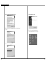
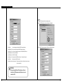
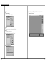
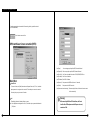
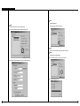
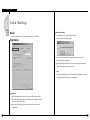
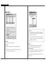
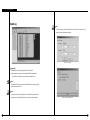
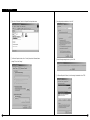
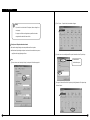
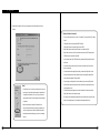
Ⅲ . Remote View Setup
System [Other]
Emergency IP address
: Transmit emergency image of message by connecting to the assigned IP address.
▶ Click [Emergency IP address] button and input IP address.
System restart time
: This function is used to automatically reboot system per day.
(This function sabilizes system operation.)
▶ Default is set to [Enable] so click on [Enable] if you do not want to use this function and
it will convert to [Disable].
Description
Watermark setup
▶ Using watermark
① This function inserts Watermark authentication mark on image to be recorded.
② When this function is selected, image will indicate WaterMark on the image.
▶ Displaying watermark text
① This function inserts Watermark authentication mark on image to be searched
② When this function is selected, image will indicate WaterMark on the image.
[Note] What is Watermark?
BMP images can be easily modified by 3rd party. To ensure the original is a true original that
has not been modified, SAMSUNG provides special protection called ‘watermarking’,
Authentication mark’, and ‘Watermark check program, which are encoded onto the image.
Any changes to an original image, including just one pixel, will inform you that the image has
been modified.
78
79
Ⅲ . Remote View Setup
3
R ecording Schedule
Record mode (C/M/S/P)
Schedule
: This function is to set recording type with day and time for selected camera.
▶ After choosing day and time from selected camera, selecting more than 1 record mode will change
selected time within selected time.
▶ If you erase all the record type from [Record Mode], selected setup time will change to no record
mode.
▶ Default is ‘Motion & sensor record’ of 24 hour continuous record.
Indication by record type
Supported record type
•
•
•
•
•
•
•
•
•
•
•
•
C : Continuous record
M : Motion record
S : sensor record
P : free-alarm record
no record
continuous record
motion record
sensor record
motion and sensor record
motion & free alarm record
sensor & free alarm record
motion &sensor & free alarm record
[Tip]
Description
① Continuous Record
Select Camera
- This is used when continuous recording is done without using motion detection.
: Select camera number.
② Motion detection record
- This is used when recording is done using motion detection.
Copy All
: This function copies selected camera’s information and paste into every camera.
③ Sensor Record
- This function is to record by inputted sensor signal.
Recording schedule type
: This function is to setup day and hour for selected camera.
- Sensor setup can be done by camera and use time. If sensor is captured within selected time,
related camera image will be recorded or related control will operate.
▶ Select recording type (C/M/S/P) from Recording Mode by selecting time or dragging area.
- Sensor input signal will be ignored if anything occurs outside the setup time.
▶ In order to setup covert hour to minute, double click on the time and it will show in minute.
- If related camera or time line is set to ‘Continuous Record’, then Sensor Record cannot be used.
④ Pre Alarm
�01min. 59min.�
- When a motion is captured on camera, then camera will record every moment of motion
occurrence in addition to five seconds before the motion was detected.
(But, recording speed may decrease if you setup several cameras with it).
- If the appropriate camera or time is set to ‘Continuous Record’ you cannot use Pre Alarm function.
80
81
Ⅲ . Remote View Setup
Simple mode
: This function lets you to select by minutes instead of hours depend on recording mode.
▶ When [Simple mode] is selected it will convert to [Advanced mode]and gives more option to
setup time. You can set different time for each time.
Set holiday
Rotate
: You may choose specific Month/Day/Year as holiday
▶ If you select [None], one day will be assigned and for that specific day only.
Holiday list
: You can pick any specific day of the year and set it as holiday
[Warning]
You must select [Save] button from [Schedule setup] in order to store
information on any changed holiday.
: This function is to show designated holiday and its repeated date or period in a list
▶ Any additional holidays will be stored in the list in an alphabetical order.
Add
: This function is to add holiday you have designated.
▶ Designated holiday will be added to [Holiday list] when you click [add].
Delete
: This function is to delete stored holiday.
Setup Holiday
▶ In order to do this, select the date you wish to delete from [Holiday list] and click [delete].
Calendar
: Select any day to designate as holiday
▶ <<
: Move to prior month
▶ >>
: Move to next month
▶ Today : Shows current Month/Day/Year
82
83
Ⅲ . Remote View Setup
4
Motion Detection
Select Area
Motion detection screen
Select All
▶ Selected area will be set as motion detection [Area draw].
▶ When you click on [Area draw all] then it will reset every area will be as motion detection area for
all camera.
Beep Sound
: When a motion is captured from linked camera within selected time, speaker from inside the system
will make BEEP sound to let you know site’s situation.
← detection area
▶ When the button is pressed: Beep sound is enabled
▶ When the button is not pressed: It will disable beep sound
☞ It only detects the motion within setup time from recording schedule.
☞ If the linked camera is set to “Continuous Recording”, Beep sound will not operate.
Brightness / Color / Contrast
: Adjusts brightness, color, contrast
▶ Camera’s default value is set to ‘18 / 8 /10’ and you can adjust from -127 to 126 by each
camera (Adjust camera to fit situation of site).
Description
Select Camera
: Select Camera.
Area of Detection
▶ To assign the detection area, place the mouse pointer over the desired area, drag it until your
aiming area is fully covered. You can designate up to 5 different detection areas in each
camera.
▶ To delete assigned area, drag out the area you wish to get rid of using left mouse button.
Sensitivity
: This function is to control sensitivity of movement every time any movement is captured on
camera.
Initial Value
▶ It will convert to factory value when you click [Default].
Screen size
: Select Screen Size.
▶ Recommended resolution size is 320 x 240.
(For 160 x 120 resolution Display & Recording speed gets better double, for 640 x 480 display
quality is good but recording speed will slow down.)
▶ Default value is 320 x 240 (based on NTSC).
▶ Supported resolution is as below :
NTSC : 160 x 120, 320 x 240, 640 x 480
PAL : 192 x 144, 384 x 288, 768 x 576
Default is set to “80” and it is our recommended value.
84
85
Ⅲ . Remote View Setup
Compression Quality
: Choose screen quality.
▶ Screen quality improves as you set to higher value but file size per frame will increase.
▶ Default value is ‘Normal’.
☞ Recording screen size and compression quality has a close relation.
Transfer Quality
: Setup the quality of image to transfer when connection with DNE(SPR Smart View)
▶ Higher value gives higher image quality but file size?per frame will increase.
▶ Default value is set to “Normal”
☞ Image size and transfer quality is closely connected for the file size to be transferred.
Ⅳ
R emote Backup Server
86
87
Ⅳ. Remote Backup Server
1
R emote Backup Server
Backup List
: Using remote drive backup function from DNE, current transmission of file size and file name,
- Using remote drive backup function from View, this function receives data while backup is in
process, and executes automatically when Viewer program is executed.
backup title, IP address of connected site, and site code will be shown in a list.
▶ Remote Backup Server program supports unlimited multi-connection and data transmission
from connected DNE can backup simultaneously.
Remote Backup Server Screen
Connection List
: This shows IP address and current connection status if connection got cancelled after
connection was made.
Password Change
Change Password
: In order to backup data in remote drive from DNE, you can select remote drive after typing IP
Description
Menu
address and password where Remote Backup Server program is installed.
This function lets you change that password.
[Change Password]
: When backup from remote drive from View, you may change the password.
[Backup log]
: Using remote drive backup function from View, you can check for list of backup data and its
information from remote backup server program.
88
89
Ⅳ. Remote Backup Server
See Backup List (Backup Log)
See List of information (View Log)
Backup log
: This shows transmission’s start time, IP address, and site code of remotely backup data in a list
Client Information
from View.
: This shows remote backup data’s IP address and View Code from View.
View log
Backup Information
: You can see a detailed information of (received) transmission data from selected DNE from [Backup
: When you setup remote backup, this shows the title for backup data.
Log].
You can also find information from appropriate list by double clicking on [Backup Log].
Delete log
: This function is to delete received information which is registered in [Backup list].
In order to delete registered list, select the list you wish to delete from [Backup list] then select
Backup Start time
: This shows start time for transmission data, the data which was remotely backup from View.
File transmission
: You can see detailed status of file transmission of remote backup data from View.
Also, it shows transmission start and end time by each file and file name etc.
[Delete log].
OK
OK
: End [Log content] Window.
: End [Backup log] widow.
90
91
Ⅴ
Intelli Upgrader
93
Ⅴ . Intelli Upgrader
1
Intelli Upgrader
Using IP address registered in connection list of Viewer program, this function will upgrade SPR
Smart View (remotely being executed from View) with a new version.
Description
Site Information
: It shows DNE information on DNE’s IP address registered in SPR Smart Viewer Program,
Site Code, and password etc. You can choose the site you want to upgrade for program.
[Tip]
Intelli Upgrader program does not support specific
change or deletion, and input process from DNE..
Execute Intelli Upgrader program
which was provided when Viewer
program was installed from desktop
window.
Select Line Type
: Possible use of line types are LAN, PSTN,ISDN and exclusive. When using ISDN or exclusive line,
communication can be made using router.
Execute Intelli Upgrader
Update Package
: This shows program information on selected version of updated package program and a
folderwhich contains original document, and result of integration test.
Package select
: Select a folder which contains original document of update package program.
Start update
: Start upgrade the program using selected DNE information and update package program.
Exit
: End Intelli Upgrader program.
94
95
Ⅴ . Intelli Upgrader
Remote Upgrade
[Program folder: Select New package version program]
[Note]
When upgrading to a new version using Intelli Update, it will not support floppy
diskette. Therefore, we commend you to upgrade after copying the whole media on
hard diskette that can hold large volume.
If there is no file or package folder in certain folder due to your mistake, or if the
damage had occur to the file, then it will not be considered as a normal package so
the program will not be upgraded normally.
① Site Information
: Select a DNE where you will upgrade the program.
③ Start update
② Package select
: Select [OK] after selecting new package version folder stored in Hard disk or its network
folder.
▶ Designated folder must have package folder (Data1, Data2, Data3, Data-a, Data-b etc.). Or
all files in package folder must contained in one folder).
: Select DNE and package folder which you will upgrade and click [Start Update].
SPR Smart View program will start to upgrade from appropriate DNE.
④ Integral test for file package
: When you assign package folder, it will show program installation status to do an integral
testing for update package program, but program will not actually be installed.
⑤ Upgrade will start after selected update package program is transmitted to DNE when you
select [Start update].
96
97
Ⅴ . Intelli Upgrader
[Program transmission and upgrade status]
Ⅵ
⑥ When you select [OK] button after upgrade is completed, system from DNE will restart
automatically and SPR Smart View will execute again.
Health Monitor
[Program transmission and upgrade are completed]
98
99
Ⅵ . Health Monitor
1
Health Monitor
Description
Health Monitor program remotely monitors connection status for DNE, camera, control, and
storage info.
Menu
: Menu is composed of [Control], [Short Cut], [Auto Check].
▶ Control Menu: [Connect], [Disconnect], and [Setup] etc.
▶ [Short Cut] Menu: Viewer program and Emergency Monitor program
Tool Bar
Execute Health Monitor program
: To execute more easily, functions are made up of icons from Tool bar.
which was provided when SPR
Connection list
smart Viewer program was
: It sends site connection information registered in Viewer program along with View code
installed from desktop window.
and name of place and you can select View Site that you wish to make connection to.
▶ List will indicate site information that have already been inputted from LAN or PSTN
according to “Type of connection”.
Execute Health Monitor
Status
: Window indicates storage status (normal/abnormal) of camera or control equipment.
▶ It will change to notepad system log file window according to menu function.
Tab Menu
: Composed of [Current State], [Memo], [System Log], and etc.
Status information from [Health Monitor] window will be changed according to menu in
order to enable and check system information.
[Note]
Health Monitor program does not support unreasonable modification,
deletion, or inputting process. It shows status of DNE which were entered
from Viewer program.
100
101
Ⅵ . Health Monitor
2
Tool Bar
Auto Check
Connect
: Connect to DNE in order to check cameras from DNE, control, and storage status.
Select [Connect] after a DNE is selected to be connect from Remote Site List.
Disconnect
: Disconnect the DNE.
Execute Center / SPR Smart Viewer program
: This function immediately executes SPR Smart Viewer program without closing Health Monitor
program. You can execute SPR Smart Viewer program when storage status of camera and control
is abnormally indicated from Health Monitor.
Site selection
: Select a DNE to be auto-checked remotely from registered DNE information.
Emergency
: Emergent message (image) received through motion detection or sensor signal from DNE can be
checked from Emergency Monitor. You can execute immediately from Health Monitor program.
Auto Check
: Using DNE information in SPR Smart Viewer program, camera’s connection, data storage, and
▶ Remote Auto-Check is possible when you select a group name like [Remote Site].
Auto-check (remote) is possible for every DNE.
Check item
: When a DNE is remotely being checked, select items to check.
▶ You can check for camera, control, and image storage status.
operational status can be auto-executed. This is more efficient to use if there are many DNE
List of items to be auto-checked from Remote DNE
information.
: Among DNE connection information registered In Connection list, indicate added DNEs to be
auto-checked remotely.
Setup
▶ It is possible to register information either individually or as a group.
: This function is to setup Health Monitor program. You may set different time for different country.
Also, SPR Smart Viewer and Health Monitor program can be executed simultaneously.
Add
: To be Auto-checked items selected from DNE can be added to Auto-check list.
102
Exit
Remove
: End Health Monitor program.
: To delete DNE connection information registered in Auto-Check list.
103
Ⅵ . Health Monitor
Auto Check - Begin Check
Remove All
: To delete all of DNE connection information registered in Auto-Check list.
Begin Check
: Check Normal/abnormal state for camera, control, storage status from Check Item list.
Cancel
: Cancel information that is setup in Auto Check and end Auto Check window at the same time.
Site info
: It shows DNE's site code and name of place.
Process info
: It indicates connection status.
Indicate connection status
: It indicates connection and on-going status, and time of connection made for DNE.
View
: You can check for information of check-completed camera, control, and storage status among
registered check list from DNE.
[Check Result of failed connection window]
[Check Result using View button]
104
105
Ⅵ . Health Monitor
OK
: End Auto-check DNE window.
Cancel
: Stop Begin-check for DNE.
3
Tab
Current State
Setup
Clock Display Format
: In order to check Camera, Control, or storage status, select Clock Display Format.
Camera status
: Indicates number of camera and output status that are currently connected to DNE.
Icon will be indicated according to the condition of camera as following.
Starting up with center
[Normal condition of camera]
: When SPR Smart Viewer program is executed, this will be automatically executed at the same
time.
[Camera is installed, but no image input]
Refresh every time to memo on active
[Camera is not installed]
: It will renew and show memo contents stored in the DNE every time [Memo] is selected
from DNE.
▶ If Refresh every time to memo on active option is not selected, it will only read initial
information of the memo when searching, and only that initial information will be indicated
Control status
: It indicates On/Off status of control equipment connected to DNE.
Icon will be indicated according to the condition of controller.
after that.
Top most window
: Set Health Monitor program at Top most mode.
[Controller is operating (ON)]
[Controller is not operating (OFF)]
▶ ‘Always on top’ function for Health Monitor program.
[Controlling equipment is not installed or not in use]
106
107
Ⅵ . Health Monitor
Memo
Record
: It indicates data’s start and end time stored in DNE.
▶ Data will continuously be stored from DNE so data storing time will be renewed time to time.
▶ You many choose a date type from Setup menu
Memo list
: From DNE, Indicate memo’s recorded time and title to current site.
Write
: This function is to input memo and its content will be stored at appropriate DNE when you click
on [OK].
Delete
: Select the parts you wish to delete and select [Delete] to erase memo stored from DNE.
View
: Select the one you wish to check from memo list and click on [View] to check it from DNE.
[Input Memo screen]
108
[View - Indicate memo contents]
109
Ⅵ . Health Monitor
System Log
View
: You can check system’s log file stored in DNE when you click on [View] from system’s log list
where files are already selected to be checked.
[Search - Search log file]
System log list
: It indicates system log (record) and log type which are stored in DNE.
▶ Type of information for system log will be prepared by DNE’s start and end time,
connection to SPR Smart Viewer, setup and execution, and search screen.
Search
: This function is to search system log file stored in DNE and part of or whole system log file
can be searched for specific time.
Delete
: This function is to delete system log file from the connected DNE. System log file will be
deleted when you click on [delete] after selection is made for the parts to be deleted.
110
[View - Indicate information of log file]
111
Ⅶ
E m e rgency Monitor
113
Ⅶ . Emergency Monitor
1
E m e rgency Monitor
Whenever an emergency message is sent via the DNE function, "Motion for Emergency
2
Toolbar
message", a function for real-time reception of emergency message and the SPR
Smart Viewer program is used to take the user directly to the DNE experiencing problems.
Execute Center / SPR Smart Viewer program
: This function executes SPR Smart Viewer program without having to end Emergency Monitor.
Execute Emergency Monitor program
When you select Urgent message from Emergency Monitor window then click [Center], you can
provided when SPR Smart Viewer was
immediately connect to appropriate DNE and execute SPR Smart Viewer program.
installed on the desktop.
Execute Health / Health Monitor program
: Health Monitor program enables to check the status of camera, control equipment (On/Off),
and status of data storage. When you select Urgent message from Emergency Monitor then
click [Health], you can immediately connect to appropriate DNE and execute SPR Smart Viewer
program.
Execute Emergency Monitor
Setup
: This function is to setup Emergency Monitor program. If you select Exit button auto-execution while
window is being restarted, it will allow you to setup system tray (icon).
Exit
: End Emergency Monitor program.
It may convert to an icon.
Hide
: Use Icon to Minimize Emergency window without ending program.
Tool bar
: Tool bar is composed of Setup icon to enable Emergency monitor program with shortcut icon which
executes SPR Smart Viewer program and Health Monitor.
Indicate Emergency message
Open (Restore)
: If any messages are received from DNE, minimized emergency monitor program will restore its
original screen size and indicate emergency screen message.
▶ Double click on minimized Emergency Monitor icon or right click to restore its original screen
size.
: This will give an urgent message in case of emergency when “Sensor for Emergency” activates.
▶ Urgent message appears if it receives a signal from sensor or image signal is not working properly.
[ Minimized icon ]
114
115
Ⅶ . Emergency Monitor
Setup
Auto run with windows startup
: It will automatically start Emergency Monitor program when window starts.
Ⅷ
Hide only
: When [Exit] button is selected, it will Hide and minimize Emergency window without having to
close the program.
Always top window
W eb DV R
: Set Emergency Monitor mode on the highest grade.
Emergency Monitor program will always stay on top of other windows.
Max number of log data (Limit : 1024)
: When indicating emergency message, this will set maximum number to be shown from
[Emergency message display window].
▶ If the messages are received more than its maximum, then it will overwrite to the old message
in the order it was received.
▶ You can indicate maximum of 1024 messages received at [Emergency message display
window].
116
117
Ⅷ. W e b D V R
1
Accessing Web DV R
② [Security Warning]
� When he WebDVR program is executed for the first time, the [Security Warrning]
message will be displayed as shown below. Select “Yes” when this message appear:
③ [Site connection]
� As soon as the WebDVR program is connected to the web site, the present
video images of the web site are displayed.
① [Accessing the WebSite]
� Enter the IP address of the web site to access in the address input window.
� Type in the site code and the password, and click on Login button to access the
Web Site.
☞ [Notice]
• Only when Site program v2.1 or higher version is installed, it is possible
to connect the WebDVR. When the site program is installed, the WebDVR
program is installed.
(For more information about installation of the WebDVR, see “Installation
of the WebDVR” part in the site user manual.)
118
119
Ⅷ. W e b D V R
2
Functions of Web DV R
1
2
3
4
5
Ⅸ
A ppendix
① If the user clicks on a displayed image, the selected image will be outlined by a blue line.
(The user can zoom in the image by double-clicking on it or pressing 1 division button.)
② The user can stop transmission of the images by clicking on Stop button.
③ The user can transmit images in 1, 4, 9 or 16 division mode.
(The user can transmit image in mother modes by clicking on Camera button at the lower
part of the GUI.)
④ The user can decide whether to display the camera number, name, and time information
on the monitoring image screen or not.
⑤ To display the monitoring image, click on the corresponding camera number.
120
121
Ⅸ . Appendix
1
Installing Center PPP
in Window s 9 8
PSTN/ISDN PPP Setup (When No Rounter is Used)
④ Setting made by KKKSetup.exe program
� Installation of telephone connection networking
� Installation of telephone connection server
� Installation of the caller
� Installation of the telephone connection adapter
� Installation of TCP/IP protocal
� Change of settings of the telephone connection server
⑤ Other
� If TCP/IP or telephone connection adapter has been installed, the corresponding item does
not needed to be installed again.
� Close windows such as “Network Environment Properties”, “Telephone Connection Server”,
and “Setup” before executing KPPPSetup.exe program .
� Do not execute KPPPSetup.exe program more than once.
(To exit the program, wait till System Rebooting message box appears.)
� In SPR Smart View S/W, select “LAN” In “Commutation Setup” field, and in SPR Smart Viewer
① PPP Setup through KPPPSetup.exe Program
� To set the PSTN, install the modem first in Windows environment and execute KPPPSetup.exe
under SPR Smart View and SPR Smart Viewer Program folders. Then, PPP setup for
PSTN/ISDN will be automactically made.
② Preparation before Installaiton
S/W, select “PSTN/ISDN (No Router)”.
� KPPPSetup.exe must be installed both in SPR Smart Viewer and SPR Smart View S/W
applications.
� Access the SPR Smart View from the SPR Smart Vewer and check if the communication
status is normal.
� The original copy of Windows98 Edition CD must be in the CD-ROM or files of Windows98
Second Edition must be copied before executing KPPPSetup.exe program.
� If the user tries to execute KPPPSetup.exe program in the system while the modem has not
been installed, the settings may not function properly.
� If the modem has not been installed, it is recommanded to install the modem and the modem
driver file before executing KPPPSetup.exe
③ PSTN and ISDN Setup in Windows98
� Install the mode for the PSTN or ISDN terminal adapter (TA) for the ISDN.
� Execute KPPPSetup.exe program.
� After PPP setup is completed by the program, reboot the system.
☞ [Notice]
• If Windows98 SE has been installed in the system from the CD-ROM, the
system may request the user to insert the original copy for the CD to the
CD-ROM. At this time, define the path of the original copy of Windows98 SE CD
(the copy folder of Windows98 SE in the hard disk or CD-ROM drive.)
• By executing KPPPSetup.exe program, the user can automatically set up the
ISDN in the same way of setting the PSTN although the router is not used and
direct connections is made.
• KPPPSetup.exe program must be installed in both the SPR Smart Viewer and
the SPR Smart View S/w applications.
� After the system is rebooted, check if the system is normally connected by the SPR Smart
Viewer program and the SPR Smart View program.
122
123
Ⅸ . Appendix
① [When there are a few dial-up servers depending on the ISDN modem}
� Basically ISDN setup will be done automatically if you run KPPPSetup.exe. However, there
might be cases that you need to setup manually when there are a few dial-up servers
depending on the ISDN modem, In that case please follow this step.
� Enter to change password and input
� When the ISDN modem supports a few dial-up servers you should select a proper dial-up
‘1234’ for all there blanks.
server that supports ISDN among the dial-up servers.
� Above step should be done after executing KPPPSetup.exe
� Choose “PPP”: Internet, Window NT Server,
Windows 98” on ‘Server Type’.
� Check “Enable Software Compression” and
② [Manual Setup]
“Require Encrypted Password” and click “Apply”
button and “OK”
� Select ‘Dial-up networking’ on
‘My Computer’ in background
� Make sure if there is “Monitoring” in the “Status”.
(The type of dial-up server is different depending
on the ISDN modem as you see above.)
☞ [Tips] Line speed
� ‘Connection’ -> ‘Dial-up server’
�If connection gets disconnected frequently or
communication status is unstable when using
PSTN, execute "Modem" from "Properties" and
select "Register information" from "General".
�From 'Modem register information' window,
� Select '38400' for maximum speed if PSTN
� Select '115200' for maximum speed if ISDN
�For safety of communication line, modem for
center and site should be set to equal.
(Connection may not work well if something like
noise and old line etc. are accompanied).
� Choose “Allow caller access”
124
125
Ⅸ . Appendix
2
Installing Center PPP
in Windows 2000/XP
⑤ Click on “Next”.
Installation
① In most cases, the modem is automatically installed in Windows 2000/XP.
(See the manual of the corresponding modem.)
② Select “Control Panel” and “Network or Dial-up Connection” folder, and click on
“Create New Connection” folder (or “Network Connection” in Windows XP).
③ Click on “Netxt”.
⑥ Click on “Next”.
④ Select “Dial-up to private network” and click on “Next” as shown below:
126
⑦ Type in “K Network” and click on “Finish”.
127
Ⅸ . Appendix
⑧ Right-click on “K Network”, and click on “Properties” from the pull-down menu.
⑨ In ‘K Network Properties’ window, click on “Security” tab, and select “Advanced(custom
settings)” Then, click on “Setting”.
⑩ After making settings as shown below, click on “OK”
⑪ When the following message box comes up, click on “No”.
⑫ In “K Network Properties” Window, click on “Networking” tab and double-click on TCP/IP.
128
129
Ⅸ . Appendix
⑬ Select “Obtain an IP address automatically” as shown below, and click on “OK”,
Then, this window will be closed.
Ⅸ . Appendix
3
Form at CD diskette
using Direct CD
[Formatting CD using Direct CD]
When you try to backup on an unformatted CD or in case where the message of backup failure has
shown, format the CD as follows.
※ Below contents is based on Direct CD v5.1. If some other message comes up, please refer to
Direct CD manual.
CD format and backup
① Select [Media Select] button in “Backup Media” -> Select CD-R/RW drive in “Local Drive”->
Click [OK]
② Insert empty CD-R/RW media and click [Format CDR/CDRW]
⑭ In ‘K Network Properties’ window, click on “OK” to close the window.
(If CD-R/RW drive is set as “auto” Direct CD program will run automatically.)
③ Check if CD-R/RW is selected when the Direct CD format utility comes up, Direct CD and click
[format CD]
⑮ Run “SPR Smart Viewer” program.
130
131
Ⅸ . Appendix
Ⅷ . Appendix
⑦ If Direct CD format utility windows come up, click this button
④ When you see a “drive format” window, input a name to “Label” and click [Start Format]
to close..
( Do not click [eject] button.)
button
⑤ “Formatting CD..” Window will appear and starts CD-R/RW media format.
⑧ Select the type, time, and camera for backup and click [OK] button.
“WRITE” LED of CD-R/RW will be turned on till CD writing is done.
Do not press button in CD-R/RW
⑨ Once the backup is done, click “Eject” button in CD-R/RW
⑥ When the format is done, below window will appear saying “CD Ready”. Then click [OK]
132
133
Ⅸ . Appendix
⑩ If “Direct CD Eject Options” window comes up, select “Close to Read on Any Computer” and
click “OK”
(If possible select “Protect CD so it cannot be written to again” not to re-write on CD-RW)
4
Form at CD using InCD
[Formatting CD using InCD
� When trying to back up data in an upformatted CD or receiving an error message after trying
to back up data, format the CD by the following procedure:
�Insert a blank CD, and click on "Format CDR/CDRW" from "Data Backup" window. Then, the following
screen will appear. Click on the "Next" button.
⑪ Below window will appear to close CD-R/RW media. Wait until this procedure ends.
�Drive selection window will appear. Click on the "Next" button.
⑫ Once the above procedure ends below window will appear.
Then eject the CD-R/RW media and click [OK] button.
134
� Disc information window will appear. Click on the "Next" button.
135
Ⅸ . Appendix
�Set the CD name.
(If you do not want to define the CD name, simply do not enter the name.)
After entering the CD name, click on the “finish” button.
� After the CD is completely formatted, the following window will appear.
(Click on the "Confirm" button to complete formatting.)
�After the CD is completely formatted, you can backup on it following the same
method as for HDD or removable drive backup.
If a different message from the above is displayed, refer to InCD manual.
☞ [Notice]
�To format a CD using InCD S/W, only CD-RW discs can be used. It is impossible to format
CD-R media using InCD S/W.
�The operating method and the setting screen differ by InCD S/W versions.
136
137
Ⅸ . Appendix
5
System setup for Audio
function
③ If the Recording window appear, go to ‘Option->Properties’
Audio volume setup for voice recording
Prior to recording voice, you need to first control audio volume for microphone.
Go to ‘Start → Program → Application → Entertainment → Volume Control’
Setup
① Execute ‘Multimedia’ in Windows control pannel.
④ Select ‘Microphone’ in ‘Properties’ window and click ‘OK’.
In order to use voice
recording function
“Microphone” should be
② Click “Recording” in Multimedia properties by clicking “Recording”button.
set from “Properties” tap.
⑤ If you click [OK] below ‘Microphone balance’ will appear in the ‘volume Control’ window.
138
139
Ⅸ . Appendix
[Notice]
② Go to ‘Options → Properties’ then, below window will appear.
• If you don’t tick on the check box of ‘Microphone’, audio recording will not
work properly.
• For proper use of Audio recording and two-way audio function above
setting should be made both Viewer and View.
PC setup for use of Microphone from advanced mode
▶ For audio recording following volume setup should be made for microphone.
▶ When the audio input through microphone is weak even in the maximized volume you can
amplify the audio input by adjusting as follows.
③ In order to use voice recording function “Microphone” should be set from “Properties” tap.
Setup
Soundcard mixer is
① Execute ‘volume control’ window by following “control panel-> Multimedia-> properties’
installed in the system.
④ You can go to ‘Advanced Controls for Microphone’ by clicking ‘Advanced’ on ‘Microphone’ taps
in ‘Volume Controls’.
140
141
Ⅸ . Appendix
⑤ Please adjust the options to fit into your system and check the sound output from ‘Other
Controls’.
2Way Audio Function will not work if,
• Your voice will not transmit to a receiver if “microphone” is not selected from “ Recording
Control”
• 2Way Audio cannot be connected from DNE to Remote.
(2Way Audio Connection is possible from Remote to DNE)
• 2Way Audio function cannot be used if Remote is not connected to DNE.
• 2Way Audio connection will end if you disconnect the most active DNE among several
DNE from Remote or switched to other DNE.
• If you end the connection for SPR Smart Viewer program then 2Way Audio function will
end as well.
• You cannot use 2Way Audio function if you do not have sound card or if sound card
driver is not installed.
• If a sound card does not support Duplex Audio, you cannot use 2Way Audio. In other
words, you should be able to hear sound (Wave) when recording Microphone (Most
recent sound card supports Full Duplex Audio).
• If you are using recording function from other software, you cannot use 2Way Audio
[Note]
• Click on ‘Mute’ which is circled on the left picture, if you do not
want any voice output from a speaker that was inputted to the
microphone but record the voice only or if you just want the
output of searched voice from the speaker only hen installing a
microphone.
function (Audio input by using microphone from sound card can only be used from one
logical program at once).
• If a sound card does not support to mix several sound sources at the same time then,
2Way Audio function will not operate normally.
(For example, when using Audio program while trying for 2Way Audio connection, 2Way
Audio will not operate properly if the sound card does support the function.)
• When the system doesn’t support ‘Microphone Boost’
function, ‘Advanced’ button may not appear. In that case you
can solve it by using a more sensitive amplified microphone.
• Sound card must be installed properly to use voice recording
function.
142
143