1
STP 1-15P14--SM-TG
Novem
mber 2009
Soldier’’s Manual and Trainer’s
T
s Guide
MOS 15
M
5P
Aviatio
A
on Ope
eration
ns Spe
ecialistt
Skill Leve
els 1, 2,
2 3, an
nd 4
DISTRIBUTION RESTRICT
TION: Approv
ved for public release; distribution is
s unlimited.
Hea
adquartters, De
epartme
ent of the Arm
my
This publication is available at:
Army Knowledge Online
(www.us.army.mil)
General Dennis J. Reimer Training and Doctrine Digital Library (http://www.train.army.mil) United States Army Publishing Agency
(http://www.army.mil/usapa)
*STP 1-15P14-SM-TG
Headquarters
Department of the Army
Washington, DC, 19 November 2009
Soldier Training Publication
No. 1-15P14-SM-TG
SOLDIER'S MANUAL and TRAINER'S GUIDE
MOS 15P Aviation Operations Specialist Skill Levels 1, 2, 3, and 4
Contents
Page
Chapter 1
Chapter 2
Chapter 3
PREFACE ....................................................................................................... v
INTRODUCTION .......................................................................................... 1-1
TRAINING GUIDE ........................................................................................ 2-1
MOS/SKILL LEVEL TASKS ........................................................................ 3-1
Skill Level 1
011-141-1076
011-141-1077
011-141-1078
011-141-1067
Subject Area 1: Operations Functions
Process Unit’s Travel Arrangements in an S-3 Operations
Sections Using Defense Travel System (DTS) ......................... 3-1
Maintain Unit's Training Events in an S-3 Operations
Section Using Digital Training Management System
(DTMS) ...................................................................................... 3-5
Process Course Enrollments in an S-3 Operations Section
Using Army Training Requirements and Resources System
(ATRRS) and Digital Training Management System (DTMS) ... 3-9
Identify Types of Orders .......................................................... 3-12
Subject Area 2: Flight Operations Functions
011-141-0001 Locate a Geographic Coordinate on a Sectional, JOG-A or
TPC ......................................................................................... 3-14
011-141-0105 Maintain DA Form 3513 Individual Flight Records Folder
(IFRF) in a Flight Operations Section ...................................... 3-17
011-141-1021 Process DOD International Flight Plan (DD Form 1801) in a
Flight Operations Section ........................................................ 3-21
Distribution Restriction: Approved for public release; distribution is unlimited. *This publication supersedes STP 1-93P1-SM, 1 October 2002 and STP 1-93P24-SM, 1 October 2002. 19 November 2009
i
STP 1-15P14-SM-TG
011-141-1023 Post Notice to Airmen (NOTAM) in a Flight Operations
Section .................................................................................... 3-24
011-141-1042 Locate Aeronautical Data in DOD Flight Information Publications (FLIPS) in a Flight Operations Section ............... 3-26
011-141-1046 Initiate Overdue Aircraft Procedures ........................................ 3-28
011-141-1072 Process Individual Flight Records in a Flight Operations Section Using Centralized Aviation Flight Records System
(CAFRS).................................................................................. 3-30
011-143-1022 Decode Military Aircraft Designation Symbols, Service, and Mission Prefixes ...................................................................... 3-41
011-141-0106 Complete DA Form 759 Series in a Flight Operations Section .................................................................................... 3-43
011-141-0113 Initiate Pre-Accident Plan......................................................... 3-45
011-141-1068 Interpret Weather Reports in a Flight Operations Section ....... 3-46
011-141-1049 Process Flight Plans for Flight Following in a Flight Operations Section.................................................................. 3-49
011-141-1048 Process Flight Orders for Flying Status in a Flight Operations Section.................................................................. 3-53
Subject Area 3: Tactical Operations Center (TOC) Functions
011-141-1065 Verify Information from Air Tasking Order (ATO), Airspace
Control Order (ACO), and Special Instructions (SPINS) in a
Flight Operations Section ........................................................ 3-60
071-329-1019 Use a Map Overlay .................................................................. 3-67
011-141-1047 Process Information in a Tactical Operations Center (TOC) ... 3-75
Subject Area 4: Tactical Operations Equipment
011-141-1075 Load the Combat Survivor Evader Locator (CSEL) Radio ....... 3-77
113-587-2071 Operate Sincgars Frequency Hopping (FH) (Net Members) ... 3-81
113-609-4000 Restore the Simple Key Loader (SKL) AN/PYQ-10 ................. 3-83
113-610-2005 Navigate Using the Defense Advanced Global Positioning System (GPS) Receiver (DAGR) ............................................ 3-85
113-610-2006 Program the Defense Advanced Global Positioning System (GPS) Receiver (DAGR) ......................................................... 3-86
113-610-2044 Navigate Using the AN/PSN-11 ............................................... 3-87
171-170-0001 Prepare Combat Messages Using FBCB2 - BFT .................... 3-89
171-170-0002 Perform Startup Procedures for Force XXI Battle Command Brigade and Below (FBCB2) - Blue Force Tracking (BFT)...... 3-95
171-170-0006 Perform Message Management Using FBCB2 - BFT ............ 3-100
171-170-0017 Employ Map Functions Using FBCB2 - BFT.......................... 3-102
171-170-0019 Employ FIPR Functions Using FBCB2 - BFT ........................ 3-106
171-170-0045 Perform Shutdown Procedures on Force XXI Battle Command Brigade and Below (FBCB2) Systems ................. 3-108
113-587-2070 Operate SINCGARS Single-Channel (SC) ............................ 3-111
113-609-2053 Operate Automated Net Control Device (ANCD) AN/CYZ-10 .............................................................................................. 3-113
ii
19 November 2009
STP 1-15P14-SM-TG
011-141-1063
011-141-1057
113-596-1068
011-141-1059
Operate the AN/VRC-100 (HF) Communication System ....... 3-115
Operate an AN/GRC-240 (Have Quick II Radio) ................... 3-119
Install Antenna Group OE-254/GRC ...................................... 3-126
Operate the Aviation Mission Planning System (AMPS) in
an S-3 Operations Section .................................................... 3-130
Skill Level 2
Subject Area 1: Operations Functions
011-141-4042 Manage Course Enrollments in an S-3 Operations Section
Using Army Training Requirements and Resources System
(ATRRS) and Digital Training Management System
(DTMS).................................................................................. 3-132
Subject Area 2: Flight Operations Functions
011-141-2029 Determine Eligibility for Flight Status..................................... 3-134
011-141-2043 Maintain DOD Flight Information Publications (FLIPS) Account in a Flight Operations Section ................................. 3-137
011-141-3010 Supervise Notice to Airmen (NOTAM) in a Flight Operations Section .................................................................................. 3-139
Subject Area 3: Tactical Operations Center (TOC) Functions
301-371-1050 Implement Operations Security (OPSEC) Measures ............ 3-141
Subject Area 4: Tactical Operations Equipment
011-141-3015 Supervise the Aviation Mission Planning System (AMPS) .... 3-145
Skill Level 3
011-141-3017
011-141-3051
011-141-3053
011-141-3054
011-141-3055
011-141-3059
Subject Area 2: Flight Operations Functions
Manage Individual Flight Records in a Flight Operations
Section Using Centralized Aviation Flight Records System
(CAFRS)................................................................................ 3-147
Process Flying Hour Program Reports.................................. 3-162
Inspect DA Form 3513 Individual Flight Records Folder (IFRF) .................................................................................... 3-164
Verify Eligibility of Aviation Badges ....................................... 3-174
Supervise Monthly Reporting on Eligibility for Hazardous Duty Incentive Pay (HDIP) .................................................... 3-177
Supervise the Loading of the Combat Survivor Evader Locator (CSEL) Radio ........................................................... 3-179
Subject Area 3: Tactical Operations Center (TOC) Functions
011-141-3056 Confirm Information from Air Tasking Order (ATO),
Airspace Control Order (ACO), and Special Instructions
(SPINS) ................................................................................. 3-183
011-141-3060 Conduct Shift Change Brief in a Tactical Operations Center
(TOC) .................................................................................... 3-184
011-141-3061 Execute Battle Rhythm in a Tactical Operations Center (TOC) .................................................................................... 3-187
19 November 2009
iii
STP 1-15P14-SM-TG
011-141-3062 Integrate Flight Operations into a Tactical Operations Center (TOC)......................................................................... 3-189
011-141-3063 Supervise Daily Operations in a Tactical Operations Center (TOC) .................................................................................... 3-192
011-141-3065 Supervise Critical Information Flow in a Tactical Operations Center (TOC)......................................................................... 3-194
Subject Area 4: Tactical Operations Equipment
071-332-5000 Prepare an Operation Overlay ............................................... 3-196
171-170-0007 Prepare Overlays Using Force XXI Battle Command Brigade and Below (FBCB2) - Blue Force Tracking (BFT).... 3-210
171-170-0021 Employ Admin Functions Using FBCB2-BFT........................ 3-215
171-170-0025 Employ Filters Functions Using FBCB2 - BFT ...................... 3-218
Skill Level 4
Subject Area 1: Operations Functions
011-141-4030 Manage Unit's Training Calendar in an S-3 Operations Section Using Digital Training Management System (DTMS).................................................................................. 3-222
011-141-4041 Manage Daily Functions in an S-3 Operations Section......... 3-225
011-141-4401 Conduct the Military Decision Making Process in a Time Constrained environment. ..................................................... 3-228
Subject Area 3: Tactical Operations Center (TOC) Functions
011-141-4044 Manage Daily Operations in a Tactical Operations Center (TOC) .................................................................................... 3-231
011-141-4045 Conduct Pre-combat Checks/Inspections (PCC/PCI) ........... 3-234
011-141-4046 Conduct Troop Leading Procedures ..................................... 3-237
011-141-4048 Relocate a Tactical Operations Center (TOC) ...................... 3-239
011-143-0039 Identify Basic Airspace Command and Control Procedures . 3-242
Subject Area 4: Tactical Operations Equipment
150-MCS-1010-6333 Manage Operational Overlays Using the Maps and Overlays Application on the AN/PYQ-6 Series, Maneuver Control System (MCS) Workstation (v6.3.3.3) ...................... 3-246
Appendix A AVIATION SCHOOL RECOMMENDED PROFESSIONAL READING ........... LIST............................................................................................................. A-1
Appendix B DEPARTMENT OF THE ARMY FORM 5164-R (HANDS-ON ......................... EVALUATION) LIST ................................................................................... B-1
Appendix C DEPARTMENT OF THE ARMY FORM 5165-R (FIELD EXPEDIENT ............ SQUAD BOOK) .......................................................................................... C-1
Appendix D NONCOMMISSIONED OFFICER CAREER PROGRESSION ................... D-1
GLOSSARY ......................................................................................... Glossary-1
REFERENCES ................................................................................References-1
iv
19 November 2009
Preface
This publication supports the Army’s revised enlisted and noncommissioned officer education system that
focuses training on force standardization. It supports the training and enrichment Soldier’s need to pursue
and enhance their military careers. Specifically, it covers operations based individual tasks required of the
specific Aviation military occupational specialty (MOS) in order to perform proficiently. Appendix A
provides an aviation school recommended professional reading list. Appendix B provides a sample DA
Form 5164-R (Hands-on Evaluation). Appendix C provides a sample DA Form 5165-R (Field Expedient
Squad Book). Appendix D provides a noncommissioned officer career progression for Career
Management Field 15, Aviation Operations. Soldiers will use the manual as a professional development
and self-evaluation tool. Soldiers should attain such a level of proficiency in performing the tasks
contained in this publication that their responses will become automatic whenever they are required to
perform, even under the most stressful circumstances.
All tasks in this guide are related to specific Career Management Field (CMF) 15 duties and
responsibilities. Reserve Soldiers in the Army National Guard and Army Reserve will use this
publication in the same self-development and evaluation mode as their active duty counterparts.
This manual applies to the Active Army, the Army National Guard/Army National Guard of the United
States, and the U.S. Army Reserve unless otherwise stated.
The proponent of this publication is Headquarters, United States Army Training and Doctrine Command
(TRADOC). Send comments and recommendations on Department of the Army (DA) Form 2028
(Recommended Changes to publications and Blank Forms) or automated link
(http://www.usapa.army.mil/da2028/daform2028.asp) to Commander, United States Army Aviation
Center of Excellence Center (USAACE), ATTN: ATZQ-TDT-E, Fort Rucker, Alabama 36362-5263.
This publication has been reviewed for operations security (OPSEC) considerations.
19 November 2009
v
This page intentionally left blank. Chapter 1
Introduction
1-1.
GENERAL.
a. This Soldier Training Publication identifies the individual military occupational specialty (MOS)
training requirement for Soldiers in MOS 15P. Commanders, trainers, and Soldiers should use it to plan,
conduct, and evaluate individual training in units. This manual is the primary MOS reference to support
the self-development and training of every Soldier. It standardizes performance steps, measures, and
evaluation guidance for all individual critical tasks for skill levels 1, 2, 3, and 4.
b. Use this manual with the Soldier's manuals of common tasks (Soldier Training Plans [STPs] 21-1
SMCT and 21-24-SMCT), Combined Arms Training Strategy (CATS), and FM 7-1 to establish effective
training plans and programs that integrate Soldier, leader, and collective tasks.
1-2. TASK SUMMARIES. Task summaries outline the wartime performance requirements of each
critical task. They provide the Soldier and the trainer with the information necessary to prepare, conduct,
and evaluate critical task training. As a minimum, task summaries include information you must know and
the skills that you must perform to standard for each task. The format for the task summaries included in
this Soldier’s manual (SM) is as follows:
a. Task Title. The task title identifies the action performed.
b. Task Number. Each task is identified by a specific number sequence. This task number, along
with the task title, will be included in any correspondence relating to the task.
c. Conditions. The task conditions identify all the equipment, tools, references, job aids, and
supporting personnel that the Soldier needs to perform the task in wartime. This section identifies any
environmental conditions that can alter task performances such as visibility, temperature, and wind. This
section also identifies any specific cues or events—a chemical attack or identification of a threat vehicle—
that trigger task performance.
d. Standards. The task standards describe how well and to what level Soldiers must perform a task
under wartime conditions. Standards are typically described in terms of accuracy, completeness, and
speed.
e. Training and Evaluation Guide. This section may contain all or part of the training information
outline, evaluation preparation subsection, and evaluation guide. The training information outline includes
detailed training information. The evaluation preparation subsection indicates necessary modifications to
task performance to train and evaluate a task that cannot be trained to the wartime standard under
wartime conditions. It also may include special training and evaluation preparation instructions to
accommodate these modifications and any instructions that should be given to the Soldier before
evaluation. The evaluation guide identifies the specific actions, known as performance measures, which
the Soldier must do to successfully complete the task. These actions are listed in a Pass/Fail format for
easy evaluation. Each evaluation guide contains a feedback statement that indicates the requirements
(for example, number of performance measures passed) for receiving a GO on the evaluation.
f. References. This section identifies references that provide more detailed and thorough
explanations of task performance requirements than that given in the task summary description.
NOTE: Some task summaries include safety statements and notes. Safety statements (warning and
caution) alert users to the possibility of immediate death, personal injury, or damage to equipment.
Notes provide a small, extra supportive explanation or hint relative to the performance measures.
19 November 2009
1-1
STP 1-15P14-SM-TG
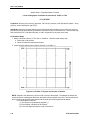
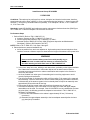
1-3. FORCE PROTECTION (COMPOSITE RISK MANAGEMENT).
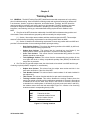
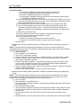
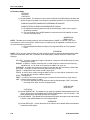
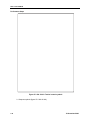
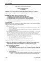
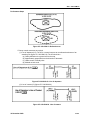
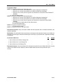
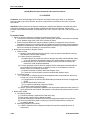
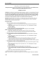
a. Composite risk management (CRM) is the Army’s primary decisionmaking process for identifying
hazards and controlling risks across the full spectrum of Army missions, functions, operations, and
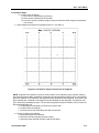
activities. (See figure 1-1.)
Figure 1-1. Composite risk management
b. CRM is a decisionmaking process used to mitigate risks associated with all hazards that have the
potential to injure or kill personnel, damage or destroy equipment, or otherwise impact mission
effectiveness. In the past, the Army separated risk into two categories, tactical risk and accident risk.
While these two areas of concern remain, the primary premise of CRM is that it does not matter where or
how the loss occurs, the result is the same—decreased combat power or mission effectiveness. The
guiding principles of CRM are as follows:
• Integrate CRM into all phases of missions and operations. Effective CRM requires that the
process be integrated into all phases of mission or operational planning, preparation,
execution, and recovery.
• Make risk decisions at the appropriate level. As a decisionmaking tool, CRM is only
effective when the information is passed to the appropriate level of command for decision.
Commanders are required to establish and publish approval authority for decisionmaking.
This may be a separate policy, specifically addressed in regulatory guidance, or addressed
in the commander’s training guidance. Approval authority for risk decisionmaking is usually
based on guidance from higher headquarters.
• Accept no unnecessary risk. Accept no level of risk unless the potential gain or benefit
outweighs the potential loss. CRM is a decisionmaking tool to assist the commander,
1-2
19 November 2009
STP 1-15P14-SM-TG
leader, or individual in identifying, assessing, and controlling risks in order to make
informed decisions that balance risk costs (losses) against mission benefits (potential
gains).
• Apply the process cyclically and continuously. CRM is a continuous process applied across
the full spectrum of Army training and operations, individual and collective day-to-day
activities and events, and base operations functions. It is a cyclic process that is used to
continuously identify and assess hazards, develop and implement controls, and evaluate
outcomes.
c. Do not be risk averse. Identify and control the hazards; complete the mission.
d. Safety demands total chain of command involvement in planning, preparing, executing, and
evaluating training. The chain of command responsibilities include the following:
(1) Commanders responsibilities are the following:
•
•
•
•
•
•
Ensure risk decisions are made at the appropriate level.
Seek optimum, not adequate, performance.
Specify the risk they will accept to accomplish the mission.
Select risk reductions provided by the staff.
Accept or reject residual risk, based on the benefit to be derived.
Train and motivate leaders at all levels to effectively use risk management concepts.
(2) Staff responsibilities are the following:
• Assists the commander in assessing risks and develops risk reduction options for
training.
• Integrates risk controls in plans, orders, METL standards, and performance measures.
• Eliminates unnecessary safety restrictions that diminish training effectiveness.
• Assesses safety performance during training.
• Evaluates safety performance during an AAR.
(3) Subordinate leaders’ responsibilities are the following:
• Apply effective risk management concepts and methods consistently to operations they
lead.
• Report risk issues beyond their control or authority to their superiors.
(4) Individual Soldier’s responsibilities are the following:
•
•
•
•
•
Report unsafe conditions, and act and correct the situation when possible.
Establish a buddy system to keep a safety watch on one another.
Take responsibility for personal safety.
Work as team members.
Modify their risk behavior.
e. Risk management is a five-step cyclic process that is easily integrated into the decisionmaking
process outlined in FM 5-0.The five steps are identifying hazards, assessing hazards, developing controls
and making risk decisions, implementing controls, and supervising and evaluating.
(1) Identify Hazards. Identify hazards to the force. Consider all aspects of current and future
situations, the environment, and known historical problems.
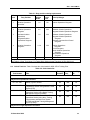
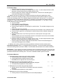
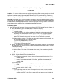
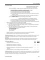
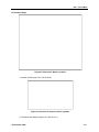
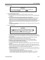
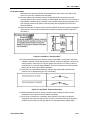
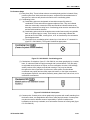
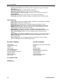
(2) Assess Hazards. Assess hazards using the risk assessment matrix in figure 1-2, page 1-5.
19 November 2009
1-3
STP 1-15P14-SM-TG
Assess the impact of each hazard in terms of potential loss and cost based on probability and severity,
and then find the block where the two intersect to determine the risk level. For example, if the hazard
probability is LIKELY and the severity is MARGINAL then the risk level is MODERATE.
(3) Develop Controls and Make Risk Decisions. Develop controls that eliminate the hazard
or reduce its risk. As control measures are developed, risks are reevaluated until all risks are reduced to a
level where benefits outweigh potential costs. Accept no unnecessary risks and make any residual risk
decisions at the proper level of command.
(4) Implement Controls. Put controls in place that eliminate the hazards or reduce their risk.
(5) Supervise and Evaluate. Enforce standards and controls. Evaluate the effectiveness of
controls and adjust/update as necessary.
NOTE: Three risk management training support packages are available to train Composite Risk
Management at individual Soldier, tactical, and operational levels of risk decisionmaking. To obtain
these training support packages, access the Army Training Support Center's Reimer Digital Library at
http://www.adtdl.army.mil/. AKO login is required, and the TSPs may be searched through the
keyword "risk". You may also contact the U.S. Army Training and Doctrine Command, ATTN: ATCS
S, 1 Bernard Road, Bldg 84, Fort Monroe, Virginia 23651-1048, or contact the United States Army
Combat Readiness/Safety Center (USACRC), ATTN: CSSC-T, 4905 5th Ave. Fort Rucker, AL 36362
5363.
f. Each Soldier is responsible for performing individual tasks that the first-line supervisor identifies
based on the unit’s mission essential task list (METL). The Soldier must perform the task to the standards
listed in the SM. If a Soldier has a question about how to do a task or which tasks in this manual he/she
must perform, he/she must ask the first-line supervisor for clarification. The first-line supervisor knows
how to perform each task or can direct the Soldier to the appropriate training materials.
1-4
19 November 2009
STP 1-15P14-SM-TG
Figure 1-2. Standard risk assessment matrix
19 November 2009
1-5
STP 1-15P14-SM-TG
1-4. SELF-DEVELOPMENT.
a. Self-development is one of the key components of the leader development program. It is a
planned progressive and sequential program followed by leaders to enhance and sustain their military
competencies. It consists of individual study, research, professional reading, practice, and selfassessment. Under the self-development concept, the Soldier or noncommissioned officer (NCO) has the
responsibility to attain proficiency and remain current in all phases of the MOS. The SM is the primary
source for the NCO to use in maintaining MOS proficiency.
b. Another important resource for self-development is the Army Correspondence Course Program,
which can be accessed through the Internet at http://www.atsc.army.mil/accp/aipdnew.asp. For
assistance, contact the Army Training Help Desk (ATHD), Department of the Army, Army Institute for
Professional Development (AIPD), U.S. Army Training Support Center (ATSC), Newport News, VA
23628-0001; (757) 878-3322 or 3335; https://athd.army.mil.
1-6
19 November 2009
Chapter 2
Training Guide
2-1. GENERAL. The MOS Training Plan (MTP) identifies the essential components of a unit training
plan for individual training. Units have different training needs and requirements based on differences
in environment, location, equipment, dispersion, and similar factors. Therefore, the MTP should be
used as a guide for conducting unit training and not a rigid standard. The MTP consists of two parts.
Each part is designed to assist the commander in preparing a unit training plan which satisfies
integration, cross training, training up, and sustainment training requirements for Soldiers in this
MOS.
a. Part One of the MTP shows the relationship of an MOS skill level between duty position and
critical tasks. These critical tasks are grouped by task commonality into subject areas.
(1) Section I lists subject area numbers and titles used throughout the MTP. These subject
areas are used to define the training requirements for each duty position within an MOS.
(2) Section II identifies the total training requirement for each duty position within an MOS and
provides a recommendation for cross training and train-up/merger training.
•
•
•
•
Duty Position Column. This column lists the duty positions of the MOS, by skill level,
which have different training requirements.
Subject Area Column. This column lists, by numerical key (see Section I), the
subject areas a Soldier must be proficient in to perform in that duty position.
Cross Train Column. This column lists the recommended duty position for which
Soldiers should be cross trained.
Train-Up/Merger Column. This column lists the corresponding duty position for the
next higher skill level or military occupational specialty code (MOSC) the Soldier will
merge into on promotion.
b. Part Two lists, by general subject areas, the critical tasks to be trained in an MOS and the type
of training required (resident, integration, or sustainment).
•
•
•
•
Subject Area Column. This column lists the subject area number and title in the
same order as Section I, Part One of the MTP.
Task Number Column. This column lists the task numbers for all tasks included in
the subject area.
Title Column. This column lists the task title for each task in the subject area.
Training Location Column. This column identifies the training location where the
task is first trained to Soldier training publications standards. If the task is first trained
to standard in the unit, the word “Unit” will be in this column. If the task is first trained
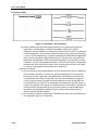
to standard in the training base, it will identify, by brevity code (such asALC and SLC),
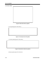
the resident course where the task was taught. Figure 2-1 contains a list of training
locations and their corresponding brevity codes.
AIT
UNIT
ALC
SLC
dL
Advanced Individual Training
Trained in the Unit
Advanced Leaders Course
Senior Leaders Course
distributed Learning
Figure 2-1. Training locations
19 November 2009
2-1
STP 1-15P14-SM-TG
•
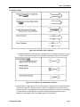
Sustainment Training Frequency Column. This column indicates the recommended
frequency at which the tasks should be trained to ensure Soldiers maintain task
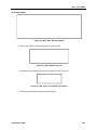
proficiency. Figure 2-2 identifies the frequency codes used in this column.
BA
AN
SA
QT
MO
BW
WK
-
Biannually
Annually
Semiannually
Quarterly
Monthly
Biweekly
Weekly
Figure 2-2. Sustainment training frequency codes
•
Sustainment Training Skill Level Column. This column lists the skill levels of the
MOS for which Soldiers must receive sustainment training to ensure they maintain
proficiency to Soldier’s manual standards.
2-2. SUBJECT AREA CODES.
Skill Level 1
1
Operations Functions
2
Flight Operations Functions
3
Tactical Operations Center (TOC) Functions
4
Tactical Operations Equipment
Skill Level 2
1
Operations Functions
2
Flight Operations Functions
3
Tactical Operations Center (TOC) Functions 4
Tactical Operations Equipment Skill Level 3
2
Flight Operations Functions
3
Tactical Operations Center (TOC) Functions 4
Tactical Operations Equipment Skill Level 4
1
Operations Functions
3
Tactical Operations Center (TOC) Functions 4
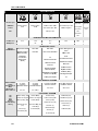
Tactical Operations Equipment 2-3. DUTY POSITION TRAINING REQUIREMENTS. Table 2-1 shows the training requirements for
MOS 15P14.
2-2
19 November 2009
STP 1-15P14-SM-TG
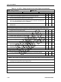
Table 2-1. Duty position training requirements
Skill
Level
Duty Position
Subject
Areas
CrossTrain
Train-Up/ Merger
1
Aviation Operations
Specialist
1-4
NA
Aviation Operations Sergeant
2
Aviation Operations
Sergeant
3-4
N/A
Assistant Aviation Operations
Sergeant/Aviation Operations Sergeant
3
Assistant Aviation
Operations
Sergeant/Aviation
Operations Sergeant
1-4
N/A
Assistant Aviation Operations
Sergeant/Aviation Operations
Sergeant
Airspace Command And Control
Sergeant
4
Aviation Operations
Sergeant
1-3-4
N/A
Aviation Operations
Sergeant
G-3 Air Sergeant
Senior Aviation Operations
Sergeant
Chief Aviation Operations
Sergeant
See Table 2-2, Sust Tng Column, For Tasks Within Subject Areas That Apply At This Skill Level.
2-4. Critical Task List. Table 2-2 shows the critical tasks for MOS 15P14 Training Plan.
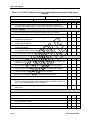
Table 2-2. Critical tasks list
Task Number
Title
Training
Location
Sust Tng
Freq
Sust Tng
SL
AIT
MO
1-4
AIT
MO
1-4
AIT
MO
1-4
AIT
MO
1-4
Skill Level 1
Subject Area: Operations Functions
011-141-1067
Identify Types of Orders
011-141-1076
Process Unit's Travel Arrangements in an S
3 Operations Section Using Defense Travel
System (DTS)
Maintain Unit's Training Events in an S-3
Operations Section Using Digital Training
Management System (DSTMS)
Process Course Enrollments in an S-3
Operations Section Using Army Training
Requirements and Resources System
(ATRRS) and Digital Training Management
System (DTMS)
011-141-1077
011-141-1078
Subject Area: Flight Operations Functions
19 November 2009
2-3
STP 1-15P14-SM-TG
Table 2-2. Critical tasks list
Task Number
011-141-0001
011-141-0105
011-141-0106
Title
Locate a Geographic Coordinate on a
Sectional, JOG-A, or TPC
Maintain DA Form 3513 (Individual Flight
Records Folder [IFRF]) in a Flight Operations
Section
Complete DA Form 759 Series in a Flight
Operations Section
011-141-0113
Initiate Pre-Accident Plan
011-141-1021
Process DOD International Flight Plan (DD
Form 1801) in a Flight Operations Section
Post Notice to Airmen (NOTAM) in a Flight
Operations Section
Locate Aeronautical Data in DOD Flight
Information Publications (FLIPs) in a Flight
Operations Section
011-141-1023
011-141-1042
011-141-1046
Initiate Overdue Aircraft Procedures
011-141-1048
Process Flight Orders for Flying Status in a
Flight Operations Section
Process Flight Plans for Flight Following in a
Flight Operations Section
Interpret Weather Reports in a Flight
Operations Section
Process Individual Flight Records in a Flight
Operations Section Using Centralized
Aviation Flight Records System (CAFERS)
Decode Military Aircraft Designation
Symbols, Service, and Mission Prefixes
011-141-1049
011-141-1068
011-141-1072
011-143-1022
Training
Location
Sust Tng
Freq
Sust Tng
SL
AIT
BM
1-4
AIT
Daily
1-4
AIT
MO
1-4
UNIT
QT
1-4
UNIT
MO
1-4
UNIT
MO
1-4
AIT
MO
1-4
UNIT
AN
1-4
UNIT
MO
1-4
AIT
MO
1-4
AIT
MO
1-4
AIT
MO
1-4
AIT
MO
1-4
AIT
MO
1-4
AIT
MO
1-4
AIT
MO
1-4
UNIT
MO
1-4
AIT
MO
1-4
UNIT
QT
1-4
UNIT
MO
1-4
AIT
MO
1-4
Subject Area: Tactical Operations Center (TOC) Functions
011-141-1047
011-141-1065
071-329-1019
Process Information in a Tactical Operations
Center (TOC)
Verify Information from Air Tasking Order
(ATO), Airspace Control Order (ACO), and
Special Instructions (SPINS) in a Flight
Operations Section
Use a Map Overlay
Subject Area: Tactical Operations Equipment
011-141-1057
011-141-1059
011-141-1063
011-141-1075
113-587-2070
2-4
Operate an AN/GRC-240 (Have Quick II
Radio)
Operate the Aviation Mission Planning
System (AMPS) in an S-3 Operations
Section
Operate the AN/VRC-100 (HF)
Communication System
Load the Combat Survivor Evader Locator
(CSEL) Radio
Operate SINCGARS Single-Channel (SC)
19 November 2009
STP 1-15P14-SM-TG
Table 2-2. Critical tasks list
Task Number
113-587-2071
Title
Operate SINCGARS Frequency Hopping
(FH) (Net Members)
113-596-1068
Install Antenna Group OE-254/GRC
113-609-2053
Operate Automated Net Control Device
(ANCD) AN/CYZ-10
Restore the Simple Key Loader (SKL)
AN/PYQ-10
Navigate Using the Defense Advanced
Global Positioning System (GPS) Receiver
(DAGR)
Program the Defense Advanced Global
Positioning System (GPS) Receiver (DAGR)
113-609-4000
113-610-2005
113-610-2006
113-610-2044
Navigate Using the AN/PSN-11
171-170-0001
Prepare Combat Messages Using FBCB2 BFT
Perform Startup Procedures for Force XXI
Battle Command Brigade and Below
(FBCB2) - Blue Force Tracking (BFT)
Perform Message Management Using
FBCB2 - BFT
171-170-0002
171-170-0006
Training
Location
Sust Tng
Freq
Sust Tng
SL
AIT
MO
1-4
AIT
MO
1-4
UNIT
MO
1-4
AIT
MO
1-4
UNIT
MO
1-4
UNIT
MO
1-4
UNIT
MO
1-4
AIT
MO
1-4
AIT
MO
1-4
AIT
MO
1-4
171-170-0017
Employ Map Functions Using FBCB2 - BFT
AIT
MO
1-4
171-170-0019
Employ FIPR Functions Using FBCB2 - BFT
AIT
MO
1-4
171-170-0045
Perform Shutdown Procedures on Force XXI
Battle Command Brigade and Below
(FBCB2) Systems
AIT
MO
1-4
UNIT
MO
2-4
Skill Level 2
Subject Area: Operations Functions
011-141-4042
Manage Unit's Course Enrollment Process in
an S-3 Operations Section Using Army
Training Requirements and Resources
System (ATRRS) and Digital Training
Management System (DTMS)
Subject Area: Flight Operations Functions
011-141-2029
Determine Eligibility for Flight Status
UNIT
MO
2-4
011-141-2043
Maintain DOD Flight Information Publications
(FLIPS) Account in a Flight Operations
Section
Supervise Notice to Airmen (NOTAM) in a
Flight Operations Section
UNIT
MO
2-4
UNIT
MO
2-4
UNIT
MO
2-4
011-141-3010
Subject Area: TOC Functions
301-371-1050
19 November 2009
Implement Operations Security (OPSEC)
Measures
2-5
STP 1-15P14-SM-TG
Table 2-2. Critical tasks list
Training
Location
Sust Tng
Freq
Sust Tng
SL
UNIT
MO
2-4
Manage Individual Flight Records in a Flight
Operations Section Using Centralized
Aviation Flight Records System (CAFRS)
Process Flying Hour Program Reports
ALC
MO
3-4
dL
MO
3-4
011-141-3053
Inspect DA Form 3513 Individual Flight
Records Folder (IFRF) in a Flight Operations
Section
dL
MO
3-4
011-141-3054
Verify Eligibility of Aviation Badges
dL
MO
3-4
011-141-3055
Supervise Monthly Reporting on Eligibility
for Hazardous Duty Incentive Pay (HDIP)
Supervise Daily functions in a Flight
Operations Section
Supervise Loading of the Combat Survivor
Evader Locator (CSEL) Radio
dL
MO
3-4
ALC
MO
3-4
ALC
MO
3-4
ALC
MO
3-4
dL
MO
3-4
dL
MO
3-4
dL
MO
3-4
dL
MO
3-4
dL
MO
3-4
ALC
MO
3-4
ALC
MO
3-4
ALC
MO
3-4
ALC
MO
3-4
Task Number
Title
Subject Area: Tactical Operations Equipment
011-141-3015
Supervise the Aviation Mission Planning
System (AMPS)
Skill Level 3
Subject Area: Flight Operations Functions
011-141-3017
011-141-3051
011-141-3064
011-141-3059
Subject Area: TOC Functions
011-141-3056
011-141-3060
011-141-3061
011-141-3062
011-141-3065
Confirm Information from Air Tasking Order
(ATO), Airspace Control Order (ACO), and
Special Instructions (SPINS)
Conduct Shift Change Brief in a Tactical
Operations Center (TOC)
Execute Battle Rhythm in a Tactical
Operations Center (TOC)
Integrate Flight Operations into a Tactical
Operations Center (TOC)
Supervise Critical Information Flow in a
Tactical Operations Center (TOC)
Subject Area: Tactical Operations Equipment
071-332-5000
Prepare an Operation Overlay
171-170-0001
Prepare/Send Combat Messages Using
FBCB2/BFT
Perform Startup Procedures for Force XXI
Battle Command Brigade and Below-Blue
Force Tracking
Perform Message Management Using
FBCB2/BFT
Prepare Overlays Using Force XXI Battle
Command Brigade and Below (FBCB2) –
171-170-0002
171-170-0006
171-170-0007
2-6
19 November 2009
STP 1-15P14-SM-TG
Table 2-2. Critical tasks list
Training
Location
Sust Tng
Freq
Sust Tng
SL
Employ Admin Functions Using FBCB2/BFT
ALC
MO
3-4
Employ Filters Functions Using FBCB2 - BFT
ALC
MO
3-4
dL
BW
4
dL
MO
4
Manage Daily Operations in a Tactical
Operations Center (TOC)
Conduct Pre-combat Checks/Inspections
(PCC/PCI)
dL
BW
4
dL
MO
4
011-141-4046
Conduct Troop Leading Procedures
dL
MO
4
011-141-4048
Relocate a Tactical Operations Center (TOC)
dL
MO
4
011-141-4401
Conduct the Military Decision Making
Process in a Time Constrained environment.
Identify Basic Airspace Command and
Control Procedures
dL
MO
4
dL
QT
4
SLC
MO
4
Task Number
Title
Blue Force Tracking (BFT)
171-170-0021
171-170-0025
Skill Level 4
Subject Area: Operations Functions
011-141-4030
011-141-4041
Manage Unit's Training Calendar in an S-3
Operations Section Using Digital Training
Management System (DTMS)
Manage Daily Functions in an S-3
Operations Section
Subject Area: TOC Functions
011-141-4044
011-141-4045
011-143-0039
Subject Area: Tactical Operations Equipment
150-MCS-1010-6333
19 November 2009
Manage Operational Overlays Using the
Maps and Overlays Application on the
AN/PYQ-6 Series, Maneuver Control System
(MCS) Workstation (v6.3.3.3)
2-7
This page intentionally left blank. Chapter 3
MOS/Skill Level Tasks
Skill Level 1
Subject Area 1: Operations Functions
PROCESS UNIT'S TRAVEL ARRANGEMENTS IN AN S-3 OPERATIONS SECTION USING DEFENSE
TRAVEL SYSTEM (DTS)
011-141-1076
Conditions: You are an aviation operations specialist assigned to an Operations Staff Officer (S-3)
section with a requirement to process travel documents. You are given a computer loaded with Defense
Travel System (DTS) software program, and access to the following references: AR 600-8-105, Defense
Travel System (DTS) Commercial Travel Office (CTO) Orientation and Users Guide, and Defense Travel
Administrator’s (DTA) Users Manual. These documents are controlled and maintained on the
http://www.defensetravel.dod.mil web site. Printed copies may be obsolete. (Please check revision
currency on web site prior to use.) Joint Federal Travel Regulations (JFTR), Volume 1, Uniformed Service
Members (for military employees, access the following web site:
http://perdiem.hqda.pentagon.mil/perdiem/trvlregs.html ), and local continuity book.
Standards: Unit’s travel requests are processed accurately, in a timely manner, and according to local
procedures identified in the unit’s continuity book.
Performance Steps
1. Refer to DTS online training center for assistance.
a. Obtain training from http://www.defensetravel.dod.mil/Training/DTS/Training.
b. Follow policy and procedures outlined in JFTR, Volume 1, appendix O.
2. Assist with self-registering.
a. Assist Soldier to self register using common access card (CAC).
b. Confirm self registration has been completed.
3. Provide necessary amenities to meet the mission.
a. Ensure that dates do not exceed elapsed time to complete assignment.
b. Minimize unproductive temporary duty (TDY) on weekends and holidays.
c. Ensure the requesting or approving official has signed a justification for any variation, and that
it has been attached to the order.
d. Ensure the military installation is shown as place of TDY when appropriate (with impact on use
of quarters).
e. If advance is given, ensure the authorized advance is supported by realistic cost estimates.
Ensure the special authorizations are traceable to support for the following items:
(1) Travel advance.
(2) Extra baggage.
(3) Taxi.
f. Determine whether the traveler has a government travel credit card.
4. Arrange mode of transportation.
a. Assist Soldier to make all arrangements through the DTS.
b. Make arrangement for tickets (air, rail, bus). Ensure costs are based on use of scheduled
airline ticket office or transportation office for travel arrangements.
c. Reserve rental cars if authorized.
(1) Ensure the rental car authorization is consistent with the following:
19 November 2009
3-1
STP 1-15P14-SM-TG
Performance Steps
(a) Need for local travel at the TDY location.
(b) Realities of public transportation.
(c) Cost of taxi service.
(d) Number of travelers.
(2) Select vehicle type as per the needs of the mission.
d. Allow for use of privately owned vehicle (POV) if authorized.
(1) Ensure expenses do not increase government costs over other practical transportation.
(2) Check post regulations to verify if authorized for in-and-around mileage.
(3) Ensure government transportation request costs are shown if the POV is not authorized.
NOTE: When the Air Mobility Command cost is the appropriate cost to the government for overseas
travel, ensure that the Air Mobility Command cost is shown instead of the government transportation
request cost.
5. Arrange lodging.
a. Assist Soldier to make arrangements through the DTS when possible.
b. Pay the actual lodging cost up to a limit specified by per diem for the area.
c. Confirm that lodging is or is not provided on post.
(1) If not, ensure the individual has a statement of nonavailability.
(2) Ensure exceptions such as "use of existing government facilities would adversely affect
the performance of the assigned mission" are traceable to support.
(3) Military members must contact the lodging facility directly to reserve lodging at a military
installation.
NOTE: Just because the quarters are available, a command cannot send a member into private sector
lodgings off the U.S. Installation and use the technical quarters 'availability' to reduce the locality meal
rate to government meal rate (GMR)/ proportional meal rate (PMR).
d. Ensure the following statement is present: "Travelers to the National Capital Region must
contact the lodging success center before making lodging arrangements."
6. Provide for meals.
a. Ensure per diem supports a realistic number of days.
(1) Pay percentage of per diem on travel days.
(2) Amount depends on departure time.
b. Military has set per diem rates. The two rates are either:
(1) The GMR when all meals on a given day are available. Pay GMR only if the following two
circumstances are met:
(a) Government lodging on a U.S. installation is available.
(b) The command controlling the mess has made the mess available to the traveler.
(2) The PMR when at least one meal a day is available.
(a) A government mess is not available on interim travel days. When actual mess
availability differs from the pretrip information, the authorizing official may authorize a
higher rate (from PMR plus incidental expenses to locality).
(b) Apply PMR when the government purchases at least one, but not all three, meals on
a calendar day through some means such as a registration fee. This does not apply
on travel days to and from the permanent duty station (PDS).
(c) The government should not pay for the same meal twice (originally by registration fee
and then again through per diem).
(3) Meals for which the government pays nothing, observe the following guidelines:
(a) A meal that is provided to the traveler for which the government pays nothing does
not affect per diem payment.
(b) A meal served on a common carrier is not "purchased by the government."
(c) The traveler must indicate on the trip record how many meals were free (purchased
by the government) and for which dates.
(d) If all three meals are provided, only the incidental expenses for that day are payable.
(e) A meal provided by a friend/relative or a common carrier do not affect per diem.
3-2
19 November 2009
STP 1-15P14-SM-TG
(f) A complimentary meal provided by a lodging establishment does not affect per diem
as long as the room charge is the same with or without meals.
NOTE: When adequate government quarters are available but a member is directed to procure private
sector lodgings off the U.S. Installation, the member is treated as though the quarters are not available,
and the locality meal rate is authorized instead of the GMR/PMR and per diem rate (continental United
States [CONUS]) or the locality incidental expense rate outside the Continental United States (OCONUS)
(unless the current per diem incidental expense rate is authorized for incidental expenses under JFTR,
paragraph T4040-A3).
7. Provide for incidental expenses incurred while traveling.
a. Pay current per diem rate per day for CONUS.
b. Pay applicable locality per diem for OCONUS.
c. Pay for tips for uniformed members as per the following guidelines:
(1) Tips aboard commercial ships to stewards and other attendants paid by or on behalf of
the dependents aboard commercial ships are authorized.
(2) Transportation-related tips for handling government property at terminals and lodgings are
authorized.
(3) Transportation-related tips for taxis, limousines, and courtesy transportation are
authorized.
d. Pay for laundry for uniformed member as per the following guidelines:
(1) Reimbursable for CONUS when travel within CONUS requires at least seven consecutive
nights of TDY lodging in CONUS.
(2) Not reimbursable for OCONUS travel. It is part of the incidental expense allowance
included within the per diem rates/actual expense allowance (AEA) authorized/approved
for OCONUS travel.
e. Pay for cost for extra baggage from airlines.
f. Use AR 600-8-105, table 12-1 as a checklist to review a completed travel document.
8. Advise Soldiers in advance of their entitlements.
9. Process travel voucher upon Soldier's return.
NOTE: A voucher is a request for reimbursement of expenses incurred during travel. After travel, a
traveler creates a voucher from an authorization to update the estimated costs with actual costs incurred
on the trip.
a. Fill out and provide a travel voucher within 5 business days of returning.
b. Electronically attach (scan or fax) all receipts for lodging and single expenses of $75 or more.
c. Comply with all local policies and procedures for their organization.
Evaluation Preparation: Setup: In a suitable training environment. Provide the Soldier with a request to
process travel documents for a Solder. Provide all items in the conditions statement.
Brief Soldier: Tell the Soldier to process the travel documents using the DTS system. Go over the
materials needed to perform the task.
Performance Measures
GO
NO-GO
1. Process travel arrangements that complied with policy and procedures outlined in
JFTR, Appendix O.
——
——
2. Ensured Soldier self-registration without error.
——
——
3. Provided Soldier with necessary amenities to meet the mission.
a. Soldier had sufficient time to complete assignment.
b. Signed justification for any variation was attached to the order.
c. Military installation was shown as place of TDY when appropriate.
d. Authorized advance was supported by realistic cost estimates.
e. Special authorizations for travel advance were traceable to support.
——
——
19 November 2009
3-3
STP 1-15P14-SM-TG
Performance Measures
GO
NO-GO
4. Arranged transportation for Soldier.
a. Costs were based on use of scheduled airline ticket office or transportation
office for travel arrangements.
b. Rental car was reserved, if authorized.
c. POV was allowed, if authorized.
d. Expenses did not increase government costs over other practical
transportation.
——
——
5. Arranged lodging for Soldier.
a. Lodging cost was paid.
b. Lodging was provided on post when available.
c. The following statement was present on travel documents: "Travelers to the
National Capital Region must contact the lodging success center before
making lodging arrangements."
——
——
6. Provided meals for Soldier
a. Per diem supported a realistic number of days.
b. Military per diem rates were paid as per the needs of the mission.
——
——
7. Provided incidental expenses for the Soldier in accordance with AR 600-8-105,
table 12-1.
——
——
8. Advised Soldier in advance of entitlements.
——
——
9. Processed travel voucher within 5 business days of Soldier's return.
a. All receipts for lodging and single expenses of $75 or more were
electronically attached to voucher (scan or fax).
b. Travel voucher complied with all local policies and procedures.
——
——
——
——
10. Prepared travel documents according to local procedures identified in the unit's
continuity book.
Evaluation Guidance: Score the Soldier GO if all performance steps are passed. Score the Soldier NO
GO if any performance steps are failed. In case of a NO-GO, brief the Soldier on the deficiency, retrain
the Soldier to perform the step correctly, and reevaluate the task.
References
Required
Local Continuity Book (011-LBC-01)
AR 600-8-105
JFTR, Volume 1
3-4
Related
19 November 2009
STP 1-15P14-SM-TG
Maintain Unit's Training Events in an S-3 Operations Section using Digital Training Management
System (DTMS)
011-141-1077
Conditions: You are an aviation operations specialist assigned to an Operations Staff Officer (S-3)
section with a requirement to schedule the unit’s training events. You are given a computer with internet
access that is loaded with Digital Training Management System (DTMS). You are given access to AR
350-1, FM 3-04.300, FM 7-0, and the Local Continuity Book.
Standards: Training events are accurately scheduled on the unit's training calendar. Training tasks are
accurately linked to events on the unit's training calendar. Unit's long-range planning calendar is
accurately maintained in a timely fashion. Unit's short range planning calendar is accurately maintained in
a timely fashion. Unit's near-term calendar is accurately maintained in a timely fashion. Unit's training
calendar is maintained according to local procedures identified in the unit's continuity book.
Performance Steps
1. Refer to the DTMS Training Website for assistance. Obtain training from
https://dtms.army.mil/training.
NOTE: As per AR 350-1, DTMS use is mandatory by all Army organizations. DTMS is a web-based
training management system that allows student management for unit training.
2. Schedule events on unit's training calendar in DTMS.
NOTE: "Schedule Event" serves as a facilitator to add tasks to unit calendars. An event is scheduled and
tasks are linked to an event. By scheduling an event, the long-range, short-range, and near-term
calendars are populated as well as unit training schedules. Once scheduled, training tasks can be linked
to events—Combined Arms Training Strategy (CATS), Collective, Local Collective, Mandatory,
Deployment, Individual, and Weapons training—as well as Training Cycles.
a. Log on to DTMS by either of the two following methods:
NOTE: To receive an account in DTMS you must have an Army Knowledge Online (AKO) account and
attend DTMS training. Contact the unit's or higher headquarters' system administrator or the DTMS Help
Desk to request training for DTMS. If you already have a DTMS account and login fails, verify user name
and password can log into AKO. Also verify you has not recently changed password with "&" followed by
a "#" symbol in it. If so, you must change the AKO password. If login to DTMS still fails, contact the unit
system administrator or the DTMS Help Desk.
(1) Type either "https://dtms.army.mil/dtms" for the actual/live site or
"https://dtms.army.mil/training" for the training site in the browser "Address" text box.
(a) Press the <ENTER> key on the keyboard or click the green arrow at the end of the
"Address" text box. The DTMS Log-on Home page opens.
(2) Log on to DTMS via AKO.
(a) Click inside the "AKO User Name" text box.
(b) Type AKO User Name. Press the <Tab> key or click inside the "Password" text box
and type AKO user password.
(c) Select the "Log in to DTMS" button. The unit home page opens.
b. Click "Training Manager."
c. See the "Training Manager" menu.
d. Click the "Schedule Event" hyperlink.
e. Fill in appropriate boxes with information according to the following standards:
(1) Enter the Event Name.
(a) Use appropriate descriptive professional titles for events that adequately and
accurately describe the event.
(b) Do not use acronyms or terms unknown outside your command, branch, or that are
not common army terminology.
(2) Ensure standardized color legends are used at all times.
(a) Use green to highlight all mandatory training requirements.
19 November 2009
3-5
STP 1-15P14-SM-TG
Performance Steps
(b) Use yellow to highlight all conferences/ meetings/ seminars/VTCs.
(c) Use blue to highlight all holidays training holidays/ social events.
(d) Use red to highlight all deployments/ Inspections.
(e) Use orange to highlight all training conducted at Joint Readiness Training Center
(JRTC)/National Training Center (NTC).
(3) Enter accurate dates and times in "Event Start and End Date/Time". Marking an event as
an All Day Event will only be done if the event will be conducted for the majority of a day
and continue past 2400 and into the next day.
(4) Check "Major Event box" if the event is labeled as such in the local continuity book.
(5) Check "Training Highlight" box if the event is defined as a Significant Activity, and
reportable, as per local continuity book. If this event meets the requirements to be
labeled a "Significant Activity reportable", it should also be checked in the “Major Event"
box.
(6) Select the correct Event Type.
(7) Enter the Risk Level from the local composite risk management worksheet.
(8) Fill in Point of Contact to include a telephone number.
(9) Fill in a location for each event.
(a) Enter any necessary grid locations in the "Notes" text box.
(b) Add the unit name to the location to identify to which unit it belongs.
f. Click on "Save."
3. Maintain unit's long-range planning calendar in DTMS by periodically checking and updating the
entries.
NOTE: Long-range planning calendar provides direction and a point of common reference for
coordinating training resources. The long-range calendar displays major training events and holidays to
aid units in long-range planning.
a. Log-on to DTMS.
b. Click "Calendar" on the DTMS menu.
c. Click on the "Long Range" hyperlink.
d. Click the "Calendar View" drop down box. Available views are Year, Month, Week, and Day.
e. Click the "<Previous Year" or "Next Year>" button to view the previous year or next year
f. View Higher Headquarters Calendar.
g. Click the "View Higher" hyperlink. The calendar will display the higher unit's name and all
events currently residing at the higher unit's Long-Range calendar. Higher headquarters'
events cannot be edited or removed by subordinate units.
h. Click "View Higher" hyperlink again. Each time the hyperlink is clicked, it shows the next higher
echelon's Long-Range calendar.
i. Click the "View Lower" hyperlink. To return to a lower unit's calendar.
4. Maintain the Short Range Planning Calendar in DTMS by periodically checking and updating the
entries.
NOTE: The Short-range planning calendar defines in greater detail the broad guidance on training
events and other activities. The short-range calendar provides weekly views for each month of unit
training events with additional filtering options by event types and units.
a. Log-on to DTMS.
b. Click "Calendars" on the DTMS menu.
c. Click "Short-Range Calendar" hyperlink. The short-range calendar page opens and defaults to
the current month.
d. View The Short-Range Calendar.
e. Click the desired "month/year" hyperlink located above the calendar to view a different month.
f. Click the "Date" hyperlink to view training for a particular day, and the calendar changes to a
day view only.
g. Click the desired event in the "Event Type" list box to view a specific event type on the
calendar.
h. Click the desired unit in the "Include Units" list box to view specific unit events on the calendar.
3-6
19 November 2009
STP 1-15P14-SM-TG
Performance Steps
i. Click the "Select All" button to choose all units.
j. Click the "control" key and click on multiple events or units. To make multiple selections, hold
down the "control" key and click on multiple events or units.
k. Click the "Apply Filter" button to apply the selected filters. Events for the selected types of
events and units appear on the calendar.
5. Maintain the near-term calendar in DTMS by periodically checking and updating the entries.
NOTE: The near-term calendar provides a view of unit training for a six-week time frame for a more
current look at training events. The calendar shows the previous week in the top row (T-1), current week
in the second row (T week) and four more rows (T+1 through T+4) for a total of six weeks. Instead of
showing the FY week number, this calendar shows the weeks marked with T-1, T wk, and T+1 in the
Sunday date block on the right hand side.
a. Log-on to DTMS.
b. Click "Calendar" on the DTMS menu.
c. Click "Near Term Calendar" hyperlink.
d. Click the "Date" hyperlink to view training for a particular day. The calendar changes to a day
view only.
e. Viewing The Near-Term Calendar.
f. Click the desired "month/year" hyperlink located above the calendar to view a different month.
g. Click the "Date" hyperlink to view training for a particular day, and the calendar changes to a
day view only.
h. Click the desired event in the "Event Type" list box to view a specific event type on the
calendar.
i. Click the desired unit in the "Include Units" list box to view specific unit events on the calendar.
j. Click the "Select All" button to choose all units.
k. Click the "control" key and click on multiple events or units. To make multiple selections, hold
down the "control" key and click on multiple events or units.
l. Click the "Apply Filter" button to apply the selected filters. Events for the selected types of
events and units appear on the calendar.
6. Maintain unit's training calendar according to guidelines outlined in the local continuity book.
Evaluation Preparation: Setup: In a suitable training environment. Provide the Soldier with training
events and training tasks to process in DTMS. Provide Soldier all items listed in the condition statement.
Brief Soldier: Tell the Soldier to schedule the training events, link training tasks to events, and verify that
the events are properly displayed in the long-term, short-term, and near-term calendars according to local
procedures outlined in the continuity book. Go over the materials needed to perform the task.
Performance Measures
GO
NO-GO
1. Scheduled training events on the unit's training calendar.
a. Training Events were scheduled in a timely fashion.
b. Training tasks were accurately linked to events.
c. Standardized color legends were used at all times.
——
——
2. Maintained the unit's long-range planning calendar.
a. Major training events and holidays were accurately displayed.
b. The calendar was updated in a timely fashion.
——
——
3. Maintained the unit's short range planning calendar.
a. Weekly views for each month of unit training events were accurately
displayed.
b. The calendar was updated in a timely fashion.
——
——
4. Maintained the unit's near-term calendar.
a. Training events for a 6-week time frame were accurately displayed.
——
——
19 November 2009
3-7
STP 1-15P14-SM-TG
Performance Measures
b. The calendar was updated in a timely fashion.
5. Maintained the unit's training calendar according to local procedures outlined in
the unit's continuity book.
GO
NO-GO
——
——
Evaluation Guidance: Score the Soldier GO if all performance steps are passed. Score the Soldier NO
GO if any performance steps are failed. In case of a NO-GO, brief the Soldier on the deficiency, retrain
the Soldier to perform the step correctly, and reevaluate the task.
References
Required
Local Continuity Book (011-LBC-01)
AR 350-1
FM 3-04.300
FM 7-0
3-8
Related
19 November 2009
STP 1-15P14-SM-TG
Process Course Enrollments in an S-3 Operations Section Using Army Training Requirements and
Resources System (ATRRS) and Digital Training Management System (DTMS)
011-141-1078
Conditions: You are an aviation operations specialist assigned to an Operations Staff Officer (S-3)
section with a requirement to process the course enrollment requests. You are given a computer with
internet access that is loaded with Digital Training Management System (DTMS) and access to Army
training requirements and resources system (ATRRS) Database (https://www.atrrs.army.mil/). You are
given DA Form 4187 (Personnel Action) and access to AR 350-1, AR 350-10, AR 600-8-6, FM 7-0, FM 3
04.300, and local continuity book.
Standards: Soldiers are enrolled in resident training base schools and distributed Learning (dL) training
courses in ATRRS. Soldiers are enrolled in post/installation schools using DTMS. The enrollments are
processed in a timely manner in accordance with (IAW) the guidelines in the local continuity book.
Performance Steps
1. Enroll students in resident training base schools and dL training courses using ATRRS.
NOTE: The Army manages training in resident training base schools and dL training courses ATRRS. All
student reservations and enrollments will be documented in ATRRS.
a. Receive course enrollment request.
b. Verify eligibility to attend courses. Refer to AR 350-1, Chapter 3, for rules governing eligibility to
attend Army schools and Defense Schools.
NOTE: Most units maintain a priority list, referred to as the order of merit list (OML) that determines who
is most qualified to attend a class and in what order they will attend.
c. Log on to ATRRS at https://www.atrrs.army.mil/. Check ATRRS for the following:
(1) Course title and number.
(2) Course length, location, and a brief scope of what the course covers.
(3) Available class dates.
(4) Available class seats.
(5) Course prerequisites and test prerequisites.
(6) Security clearance.
(7) Clothing and equipment.
(8) Government lodging.
(9) Government meals.
(10) Reporting details.
(11) Required documents.
d. Put required information on DA Form 4187.
e. Check request for accuracy.
f. Forward for authorizing official signatures.
g. Route to the next higher echelon.
2. Enroll students in post/installation schools using DTMS.
NOTE: As per AR 350-1, DTMS use is mandatory by all Army organizations. DTMS is a web-based
training management system that allows student management for unit training.
a. Receive course enrollment request.
b. Log on to DTMS by either of the two following methods:
NOTE: To receive an account in DTMS you must have an AKO account and attend DTMS training.
Contact the unit's or higher headquarters' system administrator or the DTMS Help Desk to request
training for DTMS. If you have a DTMS account and login fails, verify user name and password so that
you can log into AKO. Also verify you have not recently changed your password with "&" followed by a "#"
symbol in it. If so, you must change the AKO password. If login to DTMS still fails, contact the unit system
administrator or the DTMS Help Desk.
(1) Type either "https://dtms.army.mil/dtms" for the actual/live site or
"https://dtms.army.mil/training" for the training site in the browser "Address" text box.
19 November 2009
3-9
STP 1-15P14-SM-TG
Performance Steps
(a) Press the <ENTER> key on the keyboard or click the green arrow at the end of the
"Address" text box.
(b) The DTMS Log-on Home page opens.
(2) Log on to DTMS via AKO.
(a) Click inside the "AKO User Name" text box.
(b) Type AKO User Name. Press the <Tab> key or click inside the "Password" text box
and type AKO user password.
(c) Select the "Log in to DTMS" button. The unit home page opens.
c. Check Class Calendars for availability of classes and seats.
(1) Go to "Calendars" to view scheduled classes for the unit at installation schools only, not
ATRRS.
(2) Click "Class Calendar" hyperlink. The Class Calendar page opens.
(3) Click the desired "month/year" hyperlink located above the calendar. The appropriate
month's schedule appears.
(4) Click on class name to see details of a class.
(5) Click the "Back" button to close the View Class page.
d. Enroll Soldiers in classes.
(1) Click the "Enrollment" hyperlink. The Class Enrollment page opens.
NOTE: The Class Enrollment page displays hyperlinks for viewing Soldiers already enrolled and number
of classes selected for enrollment. Three tabs are available for “Select People,” “Select Classes,” and
“Finish Enrollment.”
(2) Click the Select People tab and use the search criteria under the People Search Criteria
section.
(a) To search by first name, click in the "First Name" text box and type name.
(b) To search by last name, click in the "Last Name" text box and type name.
(c) To search by rank, click in the "Rank" text box and type rank.
(d) To search by Student ID, click in the "social security number (SSN)" text box and
type the number.
(e) Click the "Search" button once all search criteria has been entered. The page
refreshes and the search results list is displayed.
(f) Enroll Soldiers by selecting them from the list.
(g) Click the "Add All" button to select the entire list. The list is moved to the right side of
the page.
(h) Select the Soldier and click the "Add Selected" button to move individual Soldiers.
The selected Soldier is moved to the right side of the page.
(i) Hold the <Ctrl> key and click on Soldiers to select multiple Soldiers.
(j) Click the "Remove Selected" or "Remove All" buttons to remove Soldiers from the
enrollment list (the process is the same as adding Soldiers). The Soldiers are moved
back to the left side of the page.
(k) Continue to add/remove Soldiers to/from the enrollment list until complete. When all
selections are made, click the “Select Classes” tab. The page refreshes and
indicates the number of people enrolled for the class.
NOTE: DTMS will update the system to use identification other than the Soldier’s SSN, and the DTMS
manual will be updated to reflect this change.
(3) Click the Select Classes tab to select a class and use the search criteria under the Class
Search Criteria section.
(a) Click in the "Course Name" text box and type name to search by course name.
(b) Click in the "Course Number" text box and type number to search by course number.
(c) Click the "Start Date" and/or "End Date" ellipsis buttons and add dates to search by
date of class.
(d) Click in the "Description" text box and type keyword to search by keyword.
(e) Click the "Search" button once all search criteria has been entered. The page
refreshes and the search results list is displayed.
(f) Follow instructions for adding/removing Soldiers to add/remove classes.
(g) Continue to add/remove classes to/from the enrollment list until complete. When all
3-10
19 November 2009
STP 1-15P14-SM-TG
Performance Steps
selections are made, click the Finish Enrollment tab. The page refreshes and
indicates the number of classes for enrollment.
(4) Finish Enrollment.
(a) Click the Finish Enrollment tab to complete the enrollment process. T
he page
indicates how many Soldiers are enrolled in how many classes.
(b) Click the "Finish Enrollment" button if enrollment is finished. Class Enrollment page
updates and displays the list of Soldiers, the classes they are enrolled for, and the
status.
(c) Click the "Return" button to enroll more classes. The Class Enrollment page returns
to the original view.
Evaluation Preparation: Setup: In a suitable training environment. Provide the Soldier with course
enrollment requests and all items listed in the condition statement.
Brief Soldier: Tell the Soldier to enroll students in ATRRS and DTMS according to local procedures. Go
over the materials needed to perform the task.
Performance Measures
GO
NO-GO
1. Enrolled Soldiers without error in resident training base schools and dL training
courses.
——
——
2. Processed DA Forms 4187 without error.
——
——
3. Enrolled Soldiers without error in post/installation schools.
——
——
4. Processed the enrollments in a timely manner IAW the guidelines in the local
continuity book.
——
——
Evaluation Guidance: Score the Soldier GO if all performance steps are passed. Score the Soldier NO
GO if any performance steps are failed. In case of a NO-GO, brief the Soldier on the deficiency, retrain
the Soldier to perform the step correctly, and reevaluate the task.
References
Required
Local Continuity Book (011-LBC-01)
AR 350-1
AR 350-10
AR 600-8-6
DA Form 4187
FM 3-04.300
FM 7-0
19 November 2009
Related
3-11
STP 1-15P14-SM-TG
Identify Types of Orders
011-141-1067
Conditions: You are an aviation operations specialist in a tactical operations center (TOC) with a
requirement to distinguish between different types of orders. You have access to FM 5-0 and the tactical
standing operating procedure (SOP).
Standards: Identify five different types of orders according to FM 5.0, appendix G, pages G-12 through
G-21. Identify each of the order types by purpose and/or function. Make a distinction between the
formats associated with operations orders (OPORDs), warning orders (WARNOs), and fragmentary
orders (FRAGOs).
Performance Steps
1. Identify the characteristics of an order.
a. Communication that is written, oral, or by signal.
b. Conveys instructions from a superior to a subordinate.
c. Pertains to operations and their service support.
2. Identify the types of orders.
a. OPORD.
(1) Issued by a commander as a directive to subordinate commanders.
(2) Gives a directive to execute an operation.
b. Service support order.
(1) Directs the service support of operations, including administrative movements.
(2) Provides information on sustainment to supported elements.
c. Movement order.
(1) Issued by a commander covering the details for a move of the command.
(2) Usually concerns administrative moves.
d. WARNO.
(1) Gives subordinate units and staffs a preliminary notice of an order or action to help
prepare for new missions.
(2) Amount of detail depends on the information and time available when it is issued and the
information subordinate commanders need for proper planning and preparation.
(3) Informs recipients of tasks they must do now or notifies them of possible future tasks.
(4) Does not authorize execution other than planning unless specifically stated.
e. FRAGO.
(1) Abbreviated form of an operation order (verbal, written, or digital).
(2) Issued on a day-to-day basis.
(3) Eliminates the need for restating information contained in a basic operation order.
(4) May be issued in sections.
(5) Issued after an operation order to change or modify that order or to execute a branch or
sequel to that order.
3. Identify order formats.
a. OPORD.
(1) Situation provides information essential to subordinate leader's understanding of the
situation.
(2) Mission.
(a) Task to be accomplished by the unit.
(b) Purpose for doing mission (who, what, when, where, why, and how).
(3) Execution.
(a) How the unit will accomplish its task(s) from start to finish.
(b) Identifies all mission essential tasks:
(1) The decisive points of action.
(2) The main effort.
3-12
19 November 2009
STP 1-15P14-SM-TG
Performance Steps
(4) Service support supplies the critical logistics information required to sustain the unit during
the operation.
(5) Command and signal states where command and control elements are located during the
operation.
b. WARNO follows the OPORD format and may include some or all of the following information:
(1) Series numbers, sheet numbers and names, editions, and scales of maps required (if
changed from the current OPORD).
(2) Enemy situation and significant intelligence events.
(3) Higher headquarters' mission.
(4) Mission or tasks of issuing headquarters.
(5) Commander's intent statement.
(6) Orders for preliminary actions:
(a) Intelligence.
(b) Surveillance.
(c) Reconnaissance (ISR) operations.
(7) Coordinating
instructions:
(a) Estimated timelines.
(b) Orders group meetings.
(c) Time to issue the OPORD.
(8) Service support instructions:
(a) Any special equipment needed.
(b) Preliminary unit movements.
c. FRAGO.
(1) Includes all five OPORD paragraph headings.
(a) State either "new information" or "no change" after each heading.
(b) Ensures that recipients know they have received the entire FRAGO.
(2) Address only those parts of the original OPORD that have changed.
Evaluation Preparation: Setup: In a suitable training environment, provide the Soldier with examples of
operations orders and the necessary reference to complete this task.
Brief Solder: Tell the Soldier he/she will be evaluated on his/her ability to identify five different types of
orders by purpose and/or function, and his/her ability to make a distinction between the formats
associated with OPORDs, WARNOs, and FRAGOs. Go over the materials needed to perform this task.
Performance Measures
GO
NO-GO
1. Identified types of orders by purpose and/or function IAW FM 5.0, Appendix G,
pages G-12 through G-21.
——
——
2. Explained differences in the formats of an OPORD, WARNO, and FRAGO IAW
FM 5.0, Appendix G, pages G-12 through G-21.
——
——
Evaluation Guidance: Score the Soldier GO if all performance steps are passed. Score the Soldier NO
GO if any performance steps are failed. In case of a NO-GO, brief the Soldier on the deficiency, retrain
the Soldier to perform the step correctly, and reevaluate the task.
References
Required
FM 5-0
Tactical SOP
19 November 2009
Related
3-13
STP 1-15P14-SM-TG
Subject Area 2: Flight Operations Functions
Locate a Geographic Coordinate on a Sectional, JOG-A, or TPC
011-141-0001
Conditions: Given a point on a map, protractor, FM 3-25.26, sectional, Joint Operations Graphic – Army
(JOG-A), and/or tactical pilot chart (TPC).
Standards: Determine degrees and minutes of both latitude and longitude of given point on a map and
provide the six digit grid to include grid identifier; with an accuracy of 10 meters on a 1:50,000 scale map
and 100 meters on a 1:250,000 scale map, or within .02 percent on any other scale map.
Performance Steps
1. Select a sectional, JOG-A, or TPC with a 1:50,000 or 1:250,000 scale military map.
a. Place map on flat surface.
b. Orient the map with legend at the bottom.
2. Locate degrees and minutes of latitude (figure 011-141-0001-1).
Figure 011-141-0001-1. Degrees and minutes of latitude
NOTE: Latitude is the distance a point lies north or south of the equator. The parallels of latitude are
numbered from 0 to 90 degrees both north and south with the equator being zero. The extremities are
the north pole at 90 degrees north latitude and the south pole at 90 degrees south latitude.
a. Locate degrees of latitude.
(1) The degree is symbolized by degrees (°).
(2) Each degree is divided into 60 minutes.
(3) Count the degrees along the north to south lines.
3-14
19 November 2009
STP 1-15P14-SM-TG
Performance Steps
b. Locate minutes of latitude.
(1) The minute is symbolized by minutes (').
(2) Each minute is divided into 60 seconds.
(3) Count the minute tick marks along the north to south lines. Each longer line represents
five minutes.
3. Locate degrees and minutes of longitude (figure 011-141-0001-2).
Figure 011-141-0001-2. Degrees and minutes of longitude.
NOTE: Longitude is the distance a point lies east or west of a line called the prime meridian. Starting
with 0 at the prime meridian, longitude is measured both east and west around the world. Lines east of
the prime meridian are numbered to 180 degrees and are identified as east longitude. Lines west of the
prime meridian are numbered to 180 degrees and are identified as west longitude. The direction east
(E) or west (W) must always be given. The line directly opposite the prime meridian (180º) is known as
the International Date Line.
a. Locate degrees of longitude or lines that run east to west.
b. Locate minutes of longitude.
c. Count the minute tick marks along the east to west lines.
4. Provide a 6-digit grid coordinate.
a. Determine the grid zone identifier.
b. Determine first two numbers (read left to right).
c. Determine fourth and fifth numbers (read up and down).
19 November 2009
3-15
STP 1-15P14-SM-TG
Performance Steps
d. Determine the third and sixth digit using the protractor.
Evaluation Preparation: Setup: In a suitable training environment. Provide the Soldier with five sets of
geographic coordinates to properly locate and all items in the conditions statement.
Brief Soldier: Tell the Soldier to plot the designated point on the map from the given coordinates. Go
over the materials needed to perform the task.
Performance Measures
GO
NO-GO
1. Located degrees and minutes of latitude with an accuracy of 10 meters on a
1:50,000 scale map and 100 meters on a 1:250,000 scale map, or within .02
percent on any other scale map.
——
——
2. Located degrees and minutes of longitude with an accuracy of 10 meters on a
1:50,000 scale map and 100 meters on a 1:250,000 scale map, or within .02
percent on any other scale map.
——
——
3. Provided six digit grid coordinates with an accuracy of 10 meters on a 1:50,000
scale map and 100 meters on a 1:250,000 scale map, or within .02 percent on
any other scale map.
——
——
Evaluation Guidance: Score the Soldier GO if all performance steps are passed. Score the Soldier NO
GO if any performance steps are failed. In case of a NO-GO, brief the Soldier on the deficiency, retrain
the Soldier to perform the step correctly, and reevaluate the task.
References
Required
FM 3-25.26
3-16
Related
19 November 2009
STP 1-15P14-SM-TG
Maintain DA Form 3513 (Individual Flight Records Folder [IFRF]) in a Flight Operations Section
011-141-0105
Conditions: Given the requirement to maintain DA Form 3513 (Individual Flight Records Folder, United
States Army) with the following forms and references:
1. Forms:
• DA Form 201A (Field Personnel File Divider).
• DA 759 (Individual Flight Record and Flight Certificate - Army).
• DA Form 759-1 (Individual Flight Record and Flight Certificate - Army) Aircraft Closeout
Summary.
• DA Form 759-2 (Individual Flight Record and Flight Certificate - Army) Flying Hours Worksheet.
• DA Form 759-3 (Individual Flight Record and Flight Certificate – Army, Flight Record and Flight
Pay Worksheet).
• DA Form 4186 (Medical Recommendation for Flying Duty).
• DA Form 7120-R (Commander's Task List [LRA]).
• DA Form 2408-12 (Army Aviator's Flight Record).
• DA Form 1059 (Service School Academic Evaluation Report).
• Aeronautical designation orders.
• Aviation service entry date orders.
• Initial aircrew qualification documentation for instructor pilot (IP), standardization pilot (SP),
instrument examiner, maintenance test pilot (MP), flight engineer, flight instructor, and
standardization instructor (SI).
• All flight status orders (issuance/termination/amendments).
• Termination notices (120-day) for crewmembers.
• Aviation special-skill badge orders.
• Requests for orders (RFOs) until actual orders are received.
• Other documentation, as required by the commander.
2. References:
• AR 40-501.
• AR 600-106.
• AR 600-105.
• AR 600-8-2.
• AR 95-1.
• FM 3-04.300.
• AR 25-400-2.
• Section level SOP.
• Local SOP.
Standards: Organize DA Form 3513 without discrepancies; file required forms for rated or nonrated
crewmember/noncrewmembers in accordance with (IAW) FM 3-04.300, figures 6-2 and 6-3.
Supplemental documents, medical documents, and orders are arranged on the left side of the folder.
DA Form 759 Series are arranged in on the right side of the IFRF with the most current close out on top.
Perform all actions IAW section level SOP.
Performance Steps
1. Confirm personal information label is on the top left hand corner and the disposition instructions is
on the top right hand corner of DA Form 3513, per AR 25-400-2, chapter 6, figure 6-1.
2. Arrange Files:
a. Identify forms for left side of the IFRF. Separate subject areas with DA Forms 201A that are
labeled "Supplemental Documents," "Medical," and "Orders". Arrange documents in
chronological order with most recent on top (figure 011-141-0105-1).
19 November 2009
3-17
STP 1-15P14-SM-TG
Performance Steps
Figure 011-141-0105-1. Individual flight records folder (left side)
(1) Supplemental Documents.
(a) File 120-day notices, aircrew training program (ATP) extensions/waivers, and
National Guard Bureau/U.S. Army Reserve (NGB/USAR) assignment instructions
in this section.
(b) File other miscellaneous documents and anything else the commander designates
as required in this section.
(2) Medical.
(a) File DA Form 4186 in this section. T
he individual, flight surgeon, and commander
must complete their areas of the form before it is filed in the IFRF according to AR
40-501.
(b) File copies of medical suspensions or waivers, with clearly stated periods of
retention, for any action recommended by the flight surgeon.
(3) Orders.
(a) Place in this section copies of all aviation service or flying status orders,
aeronautical certifications (certificates of completion), and suspension orders (other
than for medical disqualification). All copies of crewmember/noncrewmembers
flying status orders (to be performed and to be terminated) are retained.
(b) Place certificates of course completion for IP, instrument flight examiner, MP,
nonrated crewmember instructor, and nonrated standardization instructor in this
section. When a certificate of course completion is not available, a DA Form 1059
may be used until a replacement certificate can be obtained.
3-18
19 November 2009
STP 1-15P14-SM-TG
Performance Steps
(c) Place a copy of the most current DA Form 7120-R top page only, in this section.
This form outlines the duties authorized by the commander. Ensure signatures of
both the commander and crewmember are on the DA Form 7120-R before placing
into the IFRF.
(d) Place Senior/Master Aviator Badge orders for rated aviators in this section. A
R
600-105 contains the procedures for determining eligibility criteria for aeronautical
ratings (Senior or Master Army Aviator).
(e) Place Senior/Master Aviation Badge orders for crewmember/noncrewmembers in
this section. AR 600-106 contains the procedures for determining eligibility criteria
for aeronautical ratings (Senior or Master Aviation Badge). AR 600-8-22 contains
eligibility criteria for both badges.
(f) Place DA Form 2446 (Request for Orders) in this section. They will be maintained
in this section until the actual orders are received and then removed.
b. Identify required records for a rated or nonrated crewmember and place the records on the
right side of the IFRF (figure 011-141-0105-2).
Figure 011-141-0105-2. Individual flight records folder (right side)
(1) Arrange DA Forms 759 and 759-1 with the most current closeout on top for rated
crewmembers.
(2) Arrange DA Forms 759, 759-1, and 759-3 with the most current closeout on top for
nonrated crewmembers.
Evaluation Preparation: Setup: In a suitable training environment. Provide the Soldier with a purpose
to maintain the DA Form 3513 for an aviator, crewmember, and noncrewmember, and all items listed in
the conditions statement.
19 November 2009
3-19
STP 1-15P14-SM-TG
Brief Soldier: Tell the Soldier to place the items in the DA Form 3513 correctly. Go over the materials
needed to perform the task.
Performance Measures
GO
NO-GO
1. Labeled DA Form 3513 as per AR 25-400-2 standards.
——
——
2. Arranged forms on left side of DA Form 3513.
a. Separated documents with DA Form 201A.
b. Arranged documents in chronologically order with most recent on top.
——
——
3. Arranged forms on right side of DA Form 3513.
a. Arranged DA Forms 759 and 759-1 for rated crewmember with the most
current closeout on top.
b. Arrange DA Forms 759, 759-1, and 759-3 for nonrated crewmembers with
the most current closeout on top.
——
——
Evaluation Guidance: Score the Soldier GO if all performance steps are passed. Score the Soldier NO
GO if any performance steps are failed. In case of a NO-GO, brief the Soldier on the deficiency, retrain
the Soldier to perform the step correctly, and reevaluate the task.
References
Required
AR 25-400-2
AR 40-501
AR 600-105
AR 600-106
AR 600-8-22
AR 95-1
DA Form 1059
DA Form 201A
DA Form 2408-12
DA Form 3513
DA Form 4186
DA Form 7120-R
DA Form 759
DA Form 759-1
DA Form 759-2
DA Form 759-3
FM 3-04.300
Section Level SOP
TC 1-210
3-20
Related
19 November 2009
STP 1-15P14-SM-TG
Process DOD International Flight Plan (DD Form 1801) in a Flight Operations Section
011-141-1021
Conditions: You are an aviation operations specialist assigned to a flight operations section with aircraft
that fly to or in foreign countries. You are given DD Form 1801 (DOD International Flight Plan),
Department of Defense (DOD) Flight Information Publications (FLIPs) General Planning, International
Civil Aviation Organization (ICAO) Manual 7910, and section level standing operating procedure (SOP).
Standards: Check flight plan for correct information according to DOD FLIP General Planning, Chapter 4.
File flight plan with appropriate agency according to local SOP as dictated by the procedures established
for the dispatchers in that geographical location. Close the flight plan according to section level SOP as
dictated by procedures established for the dispatcher's geographical location.
Performance Steps
1. Check DD Form 1801 for correct information according to DOD FLIP General Planning, Chapter 4.
a. Item 9, Number and Type of Aircraft and Wake Turbulence Category.
(1) Number of aircraft. For one aircraft, indicate only the type. For more than one aircraft,
insert the number.
(2) Type of aircraft. Enter the military designator of the aircraft. Omit prefixes and suffixes
pertaining to the aircraft mission or model (C-12, C-141, T-39). If the flight consists of
different types of aircraft in formation, use the four-letter group "ZZZZ." If "ZZZZ" is used,
enter "TYP/" followed by the number and types of aircraft in item 18; for example,
TYP/4F4-4F16.
(3) Wake turbulence category. To indicate the wake turbulence category of the aircraft, use
an oblique stroke and one of the following letters:
(a) H--heavy (300,000 pounds or more).
(b) M--medium (15,501 to 299,999 pounds).
(c) L--light (15,500 pounds or less).
b. Item 10, Equipment. Enter the letter "S" if standard communication, approach, and navigational
aid equipment for the route to be flown is carried. Otherwise, use the codes listed in the DOD
FLIP General Planning.
c. Item 13, Departure Airport and Time.
(1) Airport. Enter the four-letter ICAO identifier of the airport. If the airport has no identifier,
enter ZZZZ here and the abbreviation "DEP/" followed by the name of the airport in item
18.
(2) Time. Enter the four-digit estimated off-block time.
d. Item 15, Cruising Speed, Cruising Level, and Route.
(1) Cruising speed.
(a) Enter the true airspeed, in knots, using four figures preceded by the letter "N"; for
example, N0485.
(b) If prescribed by an appropriate Air Traffic Services (ATS) authority, enter the Mach
number, to the nearest hundredth of unit Mach, preceded by the letter "M"; for
example, M082.
(2) Cruising level.
(a) For flight levels, enter the letter "F" followed by three figures; for example, F085 or
F330.
(b) For altitudes, enter the letter "A" followed by three figures (altitude in hundreds of
feet); for example, A045 or A100.
(3) Route.
(a) Flights along airways or routes. If the airport is on the airway or route, enter the
designation of the first airway or route. If the airport is not on the airway or route,
enter the code "DCT"; then enter the point where the airway or route is joined and
19 November 2009
3-21
STP 1-15P14-SM-TG
Performance Steps
the airway or route designator. Indicate each point at which the speed or level, route,
or flight rules change.
(b) Flights off airways or routes. Enter points along the route not more than 30 minutes'
flying time or 200 nautical miles apart.
e. Item 16, Destination Airport, Total Estimated Elapsed Time, and Alternate Airport(s).
(1) Destination airport and total estimated elapsed time. Enter the four-letter ICAO identifier of
the destination airport followed by (without a space) the total elapsed time. If the airport
has no location identifier, enter ZZZZ here and the abbreviation "DEST/" followed by the
airport name in item 18.
(2) Alternate airport(s). No more than two four-letter ICAO location identifiers are entered for
alternate airports. If the airports have no location identifiers, enter ZZZZ here and the
abbreviation "ALTN/" followed by the airport name in item 18.
f. Item 18, Other Information. All other information must be preceded by the abbreviations listed
in the DOD FLIP General Planning. Enter a zero if there is no other information.
g. Item 19, Supplementary Information.
(1) General. Enter or cross out the supplementary information as indicated below.
(a) Fuel. Enter the total amount of fuel on board, expressed as hours and minutes in four
figures.
(b) POB. Enter the number of passengers and crew.
(c) RDO. Cross out any "Portable Radio Frequencies" not carried as survival equipment.
(d) Type of equipment. Cross out any equipment not carried.
(e) Life jackets. Cross out "Jackets, Light Fluorescent" (sea marker dye) if life jackets
are not carried. Cross out "Light" or "Fluorescent" if jackets are not so equipped.
(f) Frequency. Enter "RDO/" followed by the "Transmitting/Receiving Frequencies" of
any life jacket radios carried.
(g) Dinghies. Cross out if dinghies are not carried.
(h) Other equipment. Indicate after "RMK/" any other survival equipment carried and any
other remarks regarding emergency and survival equipment.
(2) Remarks. Use this space to enter information for, or requests from, the departure Flight
Operations only.
(3) Crew list and passenger manifest. Attach the crew list and passenger manifest or indicate
where they are filed.
(4) Aircraft serial number and type of aircraft in flight. Enter the bureau or serial number of the
aircraft.
(5) Aircraft home station or organization. Enter the ICAO location identifier of the aircraft
home station or the organization.
(6) Name of the pilot in command and instrument rating. Enter the last name of the pilot in
command.
h. Heading.
(1) Priority indicator. Enter one of the following codes to denote the priority of the message:
SS, DD, FF, GG, JJ & KK, or LL. (For more details, refer to ICAO Annex 10, Volume II,
Chapter 4.)
(2) Addressee indicator(s). Identify each organization or agency to whom the flight plan is to
be addressed by an eight character indicator. The first four letters shall be the ICAO fourletter identifier. The next four letters (fifth through eighth) shall be as specified in the DOD
FLIP General Planning.
(3) Filing date and time. Enter a six-digit date-time group (Coordinated Universal Time [UTC])
to indicate the flight plan filing time. The first two digits will show the day of the month, and
the last four digits will show the time (for example: 061310).
(4) Originator indicator. Enter an eight-letter sequence similar to the addressee indicator
identifying the place of origin and the organization or agency originating the message.
2. File flight plan with appropriate agency according to local SOP as dictated by procedures established for the dispatchers geographical location.
3-22
19 November 2009
STP 1-15P14-SM-TG
Performance Steps
3. Close the flight plan according to local SOP as dictated by procedures established for the
dispatchers geographical location.
Evaluation Preparation: Setup: In a suitable training environment. Provide the Soldier with a completed
DD Form 1801 to process and all items listed in the Condition statement.
Brief Soldier: Tell the Soldier to verify the correctness and completeness of the flight plan and process
the flight plan according to local procedures. Go over the materials needed to perform the task.
Performance Measures
GO
NO-GO
1. Checked flight plan for correct information according to DOD FLIP General
Planning, Chapter 4 (Flight Plans).
——
——
2. Filed flight plan with appropriate agency according to local SOP as dictated by the
procedures established for the dispatchers in that geographical location.
——
——
3. Closed the flight plan according to local SOP as dictated by procedures
established for the dispatcher's geographical location.
——
——
Evaluation Guidance: Score the Soldier GO if all performance steps are passed. Score the Soldier NO
GO if any performance steps are failed. In case of a NO-GO, brief the Soldier on the deficiency, retrain
the Soldier to perform the step correctly, and reevaluate the task.
References
Required
DD Form 1801
FLIP, General Planning
ICAO Manual 7910
Section Level SOP
Local SOP
19 November 2009
Related
3-23
STP 1-15P14-SM-TG
Post Notice to Airmen (NOTAM) in a Flight Operations Section
011-141-1023
Conditions: You are a flight operations specialist working in a flight operations office with a requirement
to post NOTAMs. Given a computer with internet access, current NOTAMs, a display board/binder, DA
Form 1594 (Daily Staff Journal or Duty Officer's Log) and access to Department of Defense (DOD) Flight
Information Publication (FLIP) General Planning, FM 3-04.300, AR 95-10, and section level standing
operating procedure (SOP).
Standards: Print and post updated NOTAMs to the correct area of the NOTAM display board or binder.
Record actions on DA Form 1594. Perform all actions in accordance with (IAW) section level SOP.
Performance Steps
1. Print NOTAM
a. Go the primary web site: https://www.notams.jcs.mil/dinsQueryWeb/. Alternate web site:
https://www.notams.faa.gov/dinsqueryweb/.
b. Click text type under NOTAM retrieval box.
c. Type Airfield identifier in box under text type. Type in multiple identifiers for more than one.
d. Click on View NOTAM.
e. Check box of NOTAM.
f. Click display/print selected NOTAMS.
g. Click Print.
2. Post the NOTAMs to the correct column of the NOTAM display board or in a binder.
a. Review the entire summary for completeness and clarity.
(1) Process NOTAM summaries that contain garbled or unreadable text in one of the
following ways:
(a) Post only the columns that contain complete and readable data.
(b) Highlight the unreadable portions, posts the columns containing garbled or
unreadable text and make sure the following notice is posted at the top of the
affected columns: "HIGHLIGHTED PORTIONS GARBLED OR UNREADABLE.
CONTACT BASE OPERATIONS PERSONNEL FOR ASSISTANCE."
(2) Post Part A of each column on top and succeeding parts in sequence underneath. ( This
arranges each column of the summary in alphabetical order.)
(3) Post unpublished base NOTAMs on the NOTAM display board.
(4) Ensure the proper sign is in view when a column is not posted.
(5) Separate old and new summary parts on a display.
b. Remove the old summary and hourly update and post the new summary under the appropriate
columns. If the new summary is not received, remove the old summary and update when it
expires.
c. Annotate actions on DA Form 1594.
Evaluation Preparation: Setup: In a suitable training environment. Provide the Soldier with NOTAMs to
be posted and all items listed in the conditions statement.
Brief Soldier: Tell the Soldier to post the NOTAMs to the appropriate area as required by the local SOP.
Go over the materials needed to perform the task.
Performance Measures
GO
NO-GO
1. Posted the NOTAMs to the correct area of the NOTAM display board or binder.
——
——
2. Removed out-of-date NOTAMS.
——
——
3. Annotated actions on DA Form 1594.
——
——
3-24
19 November 2009
STP 1-15P14-SM-TG
Performance Measures
4. Performed all actions IAW section level SOP.
GO
NO-GO
——
——
Evaluation Guidance: Score the Soldier GO if all performance steps are passed. Score the Soldier NO
GO if any performance steps are failed. In case of a NO-GO, brief the Soldier on the deficiency, retrain
the Soldier to perform the step correctly, and reevaluate the task.
References
Required
AR 95-10
DA Form 1594
FAAO 7930.2
FM 3-04.300
DOD FLIP, General Planning
Section Level SOP
Local SOP
19 November 2009
Related
3-25
STP 1-15P14-SM-TG
Locate Aeronautical Data in DOD Flight Information Publications (FLIPs) in a Flight Operations
Section
011-141-1042
Conditions: You are an Aviation Operations Specialist in flight operations with a requirement to locate
aeronautical data in Department of Defense (DOD) Flight Information Publications (FLIPs). You are given
access to DOD FLIP General Planning, Visual Flight Rules (VFR) Supplement, Instrument Flight Rules
(IFR) Supplement, Flight Information Handbook (FIH), En route Low Altitude Chart, and the section level
standing operating procedure (SOP).
Standards: Locate required aeronautical data in DOD FLIP General Planning. Locate required
aeronautical data in the VFR Supplement, Locate required aeronautical data in the IFR Supplement,
Locate required aeronautical data in the FIH. Locate required aeronautical data in the En Route Low
Altitude Chart.
Performance Steps
1. Locate aeronautical data in the DOD FLIP General Planning.
a. Chapter 1, Index for Aeronautical Information. This chapter lists sections and chapters of DOD
FLIP General Planning in which information may be found and/or other primary publications to
which reference may be made.
b. Chapter 2, Explanation of Terms. This chapter lists terms and definitions, to include all those
published in the FAA Pilot/Controller Glossary plus selected ICAO and military terms.
c. Chapter 3, FLIP Program. This chapter describes the DOD FLIP program, individual FLIP
products, and related publications.
d. Chapter 4, Flight Plans. This chapter describes the procedures for using DD Form 175 (Military
Flight Plan) and DD Form 1801 (DOD International Flight Plan).
e. Chapter 5, Pilot Procedures. This chapter outlines standard pilot procedures while operating
under both Federal Aviation Administration (FAA) and ICAO control.
f. Chapter 6, International Civil Aviation Organization. This chapter identifies ICAO member
nations and international civil aviation rules and procedures.
g. Chapter 7, Operations and Firings Over the High Seas. This chapter provides guidance for the
procedures to be used by U.S. military aircrews conducting air operations or gunnery exercises
within airspace over the high seas.
h. Chapter 8, Aviation Weather Codes. This chapter explains teletypewriter weather reports and
meteorological terminal aviation reports (METARs).
i. Chapter 9, Aircraft Codes. This chapter identifies the categories of aircraft (A through E) and
the codes for aircraft identification; for example, U.S. President—Air Force 1.
j. Chapter 10, Loran/Omega Chart Coverage. This chapter contains charts depicting
Loran/Omega navigational aid coverage.
k. Chapter 11, Revisions/Quality Reports/Requisitions/ Distribution/Schedules. This chapter
provides information on submission of recommended modifications to and requisition of DOD
FLIPs. It also contains DOD FLIP revision schedules and distribution information.
2. Locate aeronautical data in the VFR Supplement.
a. The VFR Supplement is published by the National Imagery and Mapping Agency every 24
weeks.
b. It provides a city/airport cross reference listing of all airports contained within the supplement.
c. The airport directory legend shows a sample entry. Each field of the sample entry is clearly
marked for easy reference to the legend.
d. The legend explains each field and lists the possible entries.
3. Locate aeronautical data in the IFR Supplement.
a. The IFR supplement is published by the National Imagery and Mapping Agency every 8 weeks.
b. It is used as a reference and listing of IFR airfields/heliports within the United States.
3-26
19 November 2009
STP 1-15P14-SM-TG
Performance Steps
c. Like the VFR supplement, it provides a city/airport cross-reference listing of all airports
contained within the IFR supplement.
d. The airport/facility directory legend shows a sample entry. Each field of the sample entry is
clearly marked for easy reference to the legend.
e. The legend explains each field and lists the possible entries.
4. Locate aeronautical data in the FIH.
5. Locate aeronautical data in the En route Low Altitude Chart.
a. These charts are designed to provide aeronautical information for en route navigation for the
aviator operating under instrument flight rules at altitudes up to but not including 18,000 mean
sea level, (MSL).
b. The charts show airways, navigation aids (NAVAIDS), airports, airspace, special-use airspace,
and other useful information for use by the aviator.
c. The en route low altitude charts have legends that provide detailed explanations of all of the
symbols and entries used. The legend is divided into four parts:
(1) Airports.
(2) Radio aids to navigation and communication boxes.
(3) Air Traffic Services and airspace information.
(4) Special-use airspace.
Evaluation Preparation: Setup: In a suitable training environment. Provide the Soldier with a list of
information they are to locate and all items listed in the condition statement.
Brief Soldier: Tell the Soldier to locate the correct aeronautical data in the DOD FLIPS provided. Go
over the materials needed to perform the task.
Performance Measures
GO
NO-GO
1. Located required Aeronautical data in the DOD FLIP, General Planning.
——
——
2. Located required Aeronautical data in the VFR Supplement.
——
——
3. Located required Aeronautical data in the IFR Supplement.
——
——
4. Located required Aeronautical data in the FIH.
——
——
5. Located required Aeronautical data in the En Route Low Altitude Chart.
——
——
Evaluation Guidance: Score the Soldier GO if all performance steps are passed. Score the Soldier NO
GO if any performance steps are failed. In case of a NO-GO, brief the Soldier on the deficiency, retrain
the Soldier to perform the step correctly, and reevaluate the task.
References
Required
DOD FLIP
FLIP, General Planning
IFR Supplement
Section Level SOP
VFR Supplement
19 November 2009
Related
3-27
STP 1-15P14-SM-TG
Initiate Overdue Aircraft Procedures
011-141-1046
Conditions: You are an aviation operations specialist in a flight operations section and with a
requirement to initiate overdue aircraft procedures. Given telephone communications or automated
communications computer, approved flight plan for mission aircraft, DA Form 1594 (Daily Staff Journal or
Duty Officer's Log), and access to Federal Aviation Administration Order (FAAO) 7110.10, FM 3-04.300,
AR 95-11, AR 95-1, Department of Defense (DOD) Flight Information Publication (FLIP), General
Planning (GP), and section level standing operating procedure (SOP).
Standards: Determine when an aircraft is considered overdue. Initiate preliminary communication search
actions on an overdue aircraft. Provide information to the flight service station (FSS) on the overdue
aircraft. Execute operation in accordance with (IAW) the sequence in AR 95-11, Chapter 8 and section
level SOP. Record actions on DA Form 1594.
Performance Steps
1. Determine when an aircraft is considered overdue.
a. Actions by flight operations section.
(1) Initiate preliminary communications search actions when inbound aircraft (including
aircraft flying locally and round robin) has not arrived.
(2) Initiate preliminary communications search actions when communications cannot be
established within 30 minutes after estimated time of arrival (ETA).
b. Actions by Departure Station. No actions at this time.
2. Initiate preliminary communication search actions on an overdue aircraft.
a. Actions by flight operations section.
(1) Contact local air traffic control agencies. This action frequently resolves questions
regarding instrument flight rules (IFR) aircraft.
(2) Initiate a ramp check.
(3) Check adjacent airports.
(4) If 1, 2, or 3 above fails to ascertain the aircraft's whereabouts, transmit an information
request to departure station (QALQ) message to the original departure station and to each
point of intended landing. This message indicates an aircraft is overdue.
b. Actions by departure station:
(1) Complete a ramp check and local communications search for the aircraft, upon receipt of
a QALQ inquiry. This action should be completed within 15 minutes.
(2) If the aircraft is located, send a corresponding QALQ message to the destination base, the
destination tie-in flight service station (FSS), and the controlling air route traffic control
center (ARTCC).
(3) If unable to locate the aircraft, immediately provide the destination and the destination tiein FSS with all flight plan information.
3. Provide information to the FSS on an overdue aircraft.
a. Flight operations section notifies the destination tie-in FSS, by voice, of the overdue aircraft and
the preliminary communications search actions taken.
b. Departure station takes no actions at this time.
4. Record all actions on DA Form 1594.
Evaluation Preparation: Setup: In a suitable training environment. Provide the Soldier with a scenario
that requires overdue aircraft procedures to be initiated and all items listed in the condition statement.
Brief Soldier: Tell the Soldier to determine if the aircraft is overdue and to take the appropriate actions
according to the given publications. Go over the material needed to perform this task.
3-28
19 November 2009
STP 1-15P14-SM-TG
GO
NO-GO
1. Determined when an aircraft is considered overdue.
——
——
2. Initiated preliminary communication search actions on an overdue aircraft.
——
——
3. Provided information to the FSS on an overdue aircraft.
——
——
4. Recorded all actions on DA Form 1594.
——
——
5. Perform all actions according to procedures IAW the sequence in AR 95-11,
Chapter 8 and the procedures outlined in section level SOP.
——
——
Performance Measures
Evaluation Guidance: Score the Soldier GO if all performance steps are passed. Score the Soldier NO
GO if any performance steps are failed. In case of a NO-GO, brief the Soldier on the deficiency, retrain
the Soldier to perform the step correctly, and reevaluate the task.
References
Required
AR 95-1
AR 95-11
DA Form 1594
FAAO 7110.10
FM 3-04.300
FLIP, General Planning
Section Level SOP
19 November 2009
Related
3-29
STP 1-15P14-SM-TG
Process Individual Flight Records in a Flight Operations Section Using Centralized Aviation Flight
Records System (CAFRS)
011-141-1072
Conditions: You are an aviation operations specialist assigned to a flight operations section with a
requirement to process flight records. You are given a computer system with the Centralized Aviation
Flight Records System (CAFRS) program installed and a DA Form 3513 (Individual Flight Records
Folder, United States Army) containing the following:
1. Supplemental
documents.
a. Medical
Forms.
b. Orders.
c. DA Form 2408-12 (Army Aviator's Flight Record).
d. DA Form 7120-R (Commander's Task List [LRA]).
e. DA Form 759 (Individual Flight Record and Flight Certificate-Army).
f. DA Form 759-1 (Individual Flight Record and Flight Certificate-Army) Aircraft Closeout
Summary.
g. DA Form 759-2 (Individual Flight Record and Flight Certificate-Army, Flying Hours
Worksheet).
h. DA Form 759-3 (Individual Flight Record and Flight Certificate-Army, Flight Record and Flight
Pay Worksheet).
i. DA Form 4186 (Medical Recommendation for Flying Duty).
2. You are given access to the following references:
a. AR
25-400-2.
b. AR
40-501.
c. AR
95-1.
d. AR
600-8-22.
e. AR 600-105.
f. AR 600-106.
g. FM
3-04.300.
h. CAFRS
Pocket Guide.
i. Section level SOP.
Standards: Use CAFRS to process and maintain individual flight record information by performing
without errors the following functions:
1. Create an aviation person.
2. Perform
close outs.
3. Update flight information from DA Form 2408-12.
4. Update medical information from DA Form 4186.
5. Check records in and out.
6. Quarantine
records.
7. Seal
records.
8. Generate
reports.
9. Perform backup and restore procedures.
Performance Steps
1. Log onto CAFRS.
a. Access CAFRS from one of three methods.
(1) Start menu.
(2) Desktop CAFRS icon.
(3) Task bar CAFRS icon.
b. Read the Department of Defense (DOD) warning and select acknowledge.
c. Enter user identification (ID) and Password. Click OK tab.
3-30
19 November 2009
STP 1-15P14-SM-TG
Performance Steps
2. Create an aviation person.
a. Click on either of the two following options:
(1) Chose Tools from main menu options.
(a) Select Personnel Management.
(b) Click on Create Person.
(2) Select toolbar button.
(a) Select Person.
(b) Click on Create Person.
b. Select aviation personnel radio button. Enter biographical information.
(1) First Name.
(2) Middle Name.
(3) Last Name.
(4) Service.
(5) Rank.
(6) Branch.
(7) Component.
(8) All other fields are optional.
c. Click setup aviation personnel radio button. Enter ____ (status) information.
(1) Social security number (SSN). (NOTE: SSN will be replaced with personnel identifier
[PID] in version 3.)
(2) Date of birth (DOB).
(3) Aviation service entry date (ASED).
(4) Unit.
(5) Duty military occupational specialty (DMOS).
(6) Duty Position.
(7) All other fields are optional.
NOTE: Entering the aviation personnel status may activate additional required fields depending on your
selections.
d. Enter the aviator's aircraft qualifications.
(1) Use either of the following options.
(a) Click the Next button.
(b) Click the Aircraft Qualifications.
(2) Use the following drop down lists to add aircraft person is qualified in.
(a) Aircraft.
(b) Qualification Date.
(c) Night vision system (NVS) Qualification Date.
(3) Click the Add button to save data to the database.
(4) Repeat until all pertinent aircraft are added.
e. Enter the aviators training profile.
(1) Select either of the two following options.
(a) Click the Next Step (aircrew training program [ATP]) button.
(b) Click the ATP tab.
(2) Enter flight activity category (FAC).
(3) Click the Save toolbar option to save the account information to the database.
f. Choose the Close toolbar button to exit the Person Editor.
3. Perform Closeouts.
a. Close records at the following times:
(1) End of birth month (also applies to individuals who are in a nonoperational position.
(2) Upon a change of assignment or attachment governing flying duty. ( A closeout is not
required when the flight records custodian does not change.)
(3) Upon termination of flying status.
(4) Upon a change of designation (noncrewmember to crewmember).
(5) Upon a change of duty status (operational to nonoperational).
19 November 2009
3-31
STP 1-15P14-SM-TG
Performance Steps
(6) Upon change of aviation service (active or reserve).
(7) When the aviator attends a skill qualification identifier type school (such as maintenance
test pilot (MP), instructor pilot (IP) course).
(8) When disqualified from flying status.
(9) When directed by an aircraft accident investigation board.
(10) Upon death.
b. Schedule End of Birth Month Closeout.
(1) Go to the Navigation Window and the navigation (NAV) Tree.
(a) Click on the + icon to expand Aviation Personnel Folder in the NAV Tree.
(b) Click on the + icon to expand the alphabet range.
(c) Click on the + icon to expand person's name in the NAV Tree.
(d) Click on the + icon to expand the individual flight records folder (IFRF) for the
Aviation Person.
(e) RIGHT Click on the + icon to expand the current DA Form 759-series. P
roceed as
follows:
• Select Closeouts.
• Click on Schedule Closeouts.
(2) Edit "Closeout Scheduler" window.
(a) Go to Step 1 and type in the Number of closeouts to schedule.
(b) Select Update Tree button.
(c) Go to Step 2 and select the Closeout folder in the NAV Tree.
(d) Go to Step 3 and perform the following actions:
• Ensure the End of birth month radio button is selected.
• Ensure the Reason states "due to end of birth month."
• Enter the Start Date.
(e) Go to Step 4 and Generate a Validation Report. Proceed as follows:
• Click on Generate button.
• Check for accuracy of data and correct where needed.
(f) Go to Step 5 and Save Closeout Schedule. Proceed as follows:
• Click Save button.
• Select Yes button.
• Select OK button.
• Add another closeout if needed.
(g) Go to Step 6 and Close Scheduler. Click Close button.
(3) Verify Scheduled Closeout in the Navigation Window and the NAV Tree.
(a) Click on the + icon to expand Aviation Personnel Folder in the NAV Tree.
(b) Click on the + icon to expand the alphabet range.
(c) Click on the + icon to expand person's name in the NAV Tree.
(d) Click on the + icon to expand the IFRF Folder for the Aviation Person for whom you
just performed the closeout.
(e) Confirm there is a folder with the current period closeout and the following year’s
closeout.
c. Perform an End of Birth Month Closeout.
(1) Go to the Navigation Window and the NAV Tree.
(a) Click on the + icon to expand Aviation Personnel Folder in the NAV Tree.
(b) Click on the + icon to expand the alphabet range.
(c) Click on the + icon to expand person's name in the NAV Tree.
(d) Click on the + icon to expand the IFRF Folder for the Aviation Person.
(e) RIGHT Click on the + icon to expand the current DA Form 759-series. P
roceed as
follows:
• Select Closeouts Select Closeouts.
• Click on Perform Closeouts.
(2) Edit "Closeout" window.
(a) Go to Step 1and select one of the two appropriate radio button. Proceed as follows:
• Click on End of birth month.
3-32
19 November 2009
STP 1-15P14-SM-TG
Performance Steps
Click on Other Reason.
Type in the specific reason for the Closeout.
Enter new End Date.
Click Save Button.
(b) Go to Step 2 and click on Edit Closeout Remarks button. Proceed as follows:
• Click Add… Button to access the remarks list. Make sure to fill in any information
that is in parenthesis before you closeout the record.
• Click a Remark from Mandatory Remarks List to select it.
• Double-click the Remark to edit it.
• Highlight and select Delete button to delete a remark.
• Scroll to bottom of "Select Remarks to Add" window and select the Nonstandard
Remarks.
• Edit the remark as appropriate.
(c) Go to Step 2 and click on Edit Personnel Data button. Proceed as follows:
• Click on Biographical Information tab and update/verify information.
• Click on Aviation Personal Data tab and update/verify information.
• Click on Aircraft Qualification tab and update/verify information.
• Click on ATP tab and update/verify information.
(d) Go to Step 2 and click on Edit Commander button. Proceed as follows:
• Verify the name that will be printed on the closeout.
• Change the name.
• Check the "Override Unit Commander for this Closeout" box.
• Edit Name, Rank, and Branch.
• Click Save Button.
(e) Skip Step 3.
(f) Go to Step 4 and click on Generate button. Check for accuracy of data and correct
where needed.
(g) Go to Step 5 and submit the closeout to the commander. Proceed as follows:
• Click the Submit to Commander button.
• Notify the commander by email or in person to digitally sign the closeout. This
process sends a message to the Aviation person you are closing-out, notifying
them of the action taken on their record.
• Click Yes button on "Confirm Submit" window.
• Click Yes button on "Perform Submit" window.
• Click No button on "Perform Submit" window if person is leaving the unit.
• Click Yes button to answer "Are you ready to certify it right now?" if the
commander is there to sign.
d. Perform a Closeout on an Overdue Closeout.
(1) Click on the + icon to expand person's file in the NAV Tree.
(2) Click on the + icon to expand person's file in the NAV Tree.
(a) Click on Closeouts.
(b) Click on Perform a Closeout.
(c) Ensure End of birth month radio button is selected.
(d) Select Edit Closeout Remarks: Proceed as follows:
• Click on Add.
• Press and hold the Ctl key and select the following two mandatory comments:
"Aviator has completed ATP requirements."
"Aviator has completed ___(#) months of operational flying duty credit."
• Click OK.
• Double-click on the "...operational flying duty credit" remark.”
• Edit it to read "Aviator has completed ___(#) months of operational flying duty
credit."
• Click Save.
(3) Generate a validation report by clicking the Generate button.
(4) Prepare for Commander's signature.
•
•
•
•
19 November 2009
3-33
STP 1-15P14-SM-TG
Performance Steps
(a) Click on Submit to Commander.
(b) Click Yes In the Confirm Submit dialog.
(c) Click No In the popup window Perform Closeout asking if you are ready to certify it.
(5) Verify the "Pending" status of the closeout in the NAV Tree.
e. Make a correction to a DA Form 2408-12.
(1) Expand a person's IFRF in the NAV Tree by clicking on the + icon.
(2) Expand folder Closeout (1) (Pending).
(a) Click on the + icon.
(b) Click on Closeout (1) (Pending).
(c) Click on Closeouts.
(d) Click on Cancel Closeout Request.
(3) Verify that the status of that closeout in the NAV Tree has returned to "Pending."
(4) Expand a person's IFRF in the NAV Tree by clicking on the + icon.
(5) Expand the Closeout (1) (Overdue) folder.
(a) Click on the + icon.
(b) Right-click on DA Form 2408-12 for which you are making changes. Proceed as
follows:
• Click on year.
• Click on month.
• Click on date.
• Click Open.
• Enter data to make corrections.
• Right-click on person's name.
• Select Edit.
• Make the correction.
• Click Add.
• Click Save.
(c) Verify the "Pending" status of the closeout in the NAV Tree.
4. Create DA Form 2408-12.
a. Use one of the following five methods to display the DA Form 2408-12 **New** window.
(1) From the Menu bar, select File > New > DA Form 2408-12.
(2) From the Menu bar, select IFRF > DA Form 2408-12 > Create.
(3) From the tool bar select DA Form 2408-12 > Create.
(4) Right-click on the Aviation Person's name in the NAV Tree window, then select New > DA
2408-12.
(5) Press [Ctrl + 2].
b. Enter Data into Flight Record tab.
(1) DATE: Enter the date of the flight using the Windows calendar.
(2) SERIAL NUMBER: Enter the serial number of the aircraft.
(3) MODEL: Select the model of the aircraft flown from the pull down menu list.
(4) ORGANIZATION: Enter the unit or activity to which the craft is assigned.
(5) STATION: Enter the aircraft's home station.
(6) FLIGHT DATA: Enter the number of the flight (For example, if it is the first flight of the
mission day, enter a 1 here).
(7) FROM: Enter the airfield or place the flight originated from. The word LOCAL may be used
in this block for flights within the local flying area.
(8) TO: Enter any intermediate stops during the flight (will be left blank if LOCAL was used in
the FROM section).
(9) TO: Enter the airfield or place flown to (will be left blank if LOCAL was used in the FROM
section). This would be the final landing.
(10) TIME. FROM: Enter the time (24-hour clock) of take off.
(11) TO: Enter the time (24-hour clock) of intermediate landing.
(12) TO: Enter the time (24-hour clock) of final landing.
3-34
19 November 2009
STP 1-15P14-SM-TG
Performance Steps
(13) LDG: STD/AUTO. Enter the total number of standard landings, and touchdown auto
rotations made during this flight.
(14) MISSION ID: STD. Enter the mission symbol from the pull down menu that describes the
purpose of the flight.
(15) NAME: Select the name of each crewmember for each flight.
(16) DS: Enter the flying duty symbol.
(17) FS: Enter the flight condition symbol.
(18) HR: Enter the flying time, in hours and tenths, flown for each duty and flight symbol.
(19) S: Select the seat each crewmember sat in for the flight, "F" for Front, "B" for Back. This
applies to tandem seat aircraft only (AH-64). This selection will only be available for the
AH-64.
(20) Select the ADD button to populate the person and data in the personnel data display field.
c. Edit/remove Personnel Data.
(1) Right-click in the row associated with the entry to display the Edit or Remove options.
(2) Select the Edit option to replace or update information.
(3) Select Remove option to delete information.
(4) Select save to accept changes.
(5) Confirm or Deny by selecting Yes or No.
d. Update/Modify.
(1) Double-click the record you want to update.
(2) Select the individual's name on the tool bar.
(3) Select DA Form 2408-12.
(4) Select Update/Modify on the tool bar.
(5) Update /modify the record.
(6) Select save to accept changes.
(7) Confirm or Deny by selecting Yes or No.
5. Prepare DA Form 4186.
a. Create DA Form 4186 for an Annual Medical Examination upon receiving SIGNED DA Form
4186 for Temporary Medical Suspension from Flight Surgeon.
(1) Open a blank DA Form 4186 by one of the following five methods:
(a) Menu: File. Proceed as follows:
• New.
• DA Form 4186.
(b) Tool bar: DA Form 4186.
(c) Create.
(d) IFRF. Proceed as follows:
• DA Form 4186.
• Create.
(e) [Ctl + 4].
(2) Enter DA Form 4186 info:
(a) Enter only the data from the original signed DA Form 4186.
(b) Select name from pull down list.
(c) Enter the Effective date and Expiration date (Date Clearance Expires).
(d) Check Yes or No for glasses.
(e) Select Medical Examination in the "Medical Clearance is Recommended by the
Following Reasons" box.
NOTE: Due to privacy laws, Health Insurance Portability and Accountability Act (HIPPA) recommended
to only use full flying duties (FFD) or duty not involving/including flying (DNIF) in the remarks section.
There may be more information on the paper copy.
(f) Complete the following steps:
• Check the same boxes that are checked on the signed original.
• Click on Save button at the top of the window.
• Confirm or Deny by selecting Yes or No.
• Select OK for Record Saved.
19 November 2009
3-35
STP 1-15P14-SM-TG
Performance Steps
b. Create Temporary Medical Suspension (Down Slip) upon receiving SIGNED DA Form 4186.
(1) Create new DA Form 4186.
(2) Fill in the "TO" and "FROM" fields.
(3) Select name from pull down list.
NOTE: Do not change any information between the name and "The Following Disqualifying Action is
Recommended"
(4) Fill out the information in the "The Following Disqualifying Action is Recommended" box
with information from the signed DA Form 4186.
(5) Select the Recommended Disqualifying Action from the pull down list.
(6) Type in duration time.
(7) Type in the "Incapacity Date."
(8) Select "YES or "NO" for Simulator and Run-up duties.
NOTE: Due to privacy laws, HIPPA recommended to only use FFD or DNIF in the remarks section.
There may be more information on the paper copy.
(9) Click on Save button at the top of the window.
(10) Confirm or Deny by selecting Yes or No.
(11) Select OK for Record Saved.
(12) See the Down slip (DN) in the DA 4186 folder in the Navigation Tree to confirm action has
been completed.
c. Create Add an Extension upon receiving SIGNED DA Form 4186 for Add an Extension from
Flight Surgeon.
(1) Create a new DA Form 4186.
(2) Select name from pull down list.
(3) Check the EXTENSION box beside the name.
NOTE: The "Other" block is automatically checked when EXTENSION is selected.
(4) Put effective dates of the extension.
NOTE: The "Other" block is automatically checked when EXTENSION is selected.
(5) Select the button and Save.
(6) Confirm or Deny by selecting Yes or No.
(7) Select OK for Record Saved.
(8) See the progression of DA Form 4186 for the individual for this period in the Navigation
Tree.
d. Create Termination of Temporary Medical Suspension (Up Slip) upon receiving SIGNED DA
Form 4186 for Termination of Temporary Medical Suspension from Flight Surgeon.
(1) Create new DA From 4186.
(2) Fill in the "TO" and "FROM" fields.
(3) Select name from pull down list.
(4) Put effective dates of the new Up Slip.
(5) Check Yes or No for glasses.
(6) Select Termination of Temporary Medical Suspension in the "Medical Clearance is
Recommended by the Following Reasons" box.
NOTE: Do Not Fill out the information in the "The Following Disqualifying Action is Recommended" box
NOTE: Due to privacy laws, HIPPA recommended to only use FFD or DNIF in the remarks section.
There may be more information on the paper copy.
(7) Confirm or Deny by selecting Yes or No.
(8) Select OK for Record Saved.
(9) Click on Save button at the top of the window.
(10) Confirm or Deny by selecting Yes or No.
(11) Select OK for Record Saved.
(12) See the progression of DA Form 4186s for the individual for this period in the Navigation
Tree.
6. Check Out/In a Record
a. Perform Check Out/In of records when you need to move the record to another computer. F
or
example, if multiple records require action, you can move the records from one computer to
3-36
19 November 2009
STP 1-15P14-SM-TG
Performance Steps
other computers and have other staff members assist in the work.
NOTE: Check Out/In does not allow a "Primary Records (Owned)" to be rechecked in. If you receive an
"Attention" message that states "The user (Doe, SFC John) is already owned. If another record is also
being shown as owned, contact the administrator!" someone has reclaimed a record that they checked
out. This creates duplicate records in the system. In this case you will have to determine which record is
correct. If it is the record to be checked in, you can check out the record in the system, and then check in
the correct one from device. (Destroy the older record checked out.)
b. Check Out a Record.
(1) Open by selecting the Check Out/In tab on the toolbar.
(2) Select Network or Device from the drop-down menu.
(3) See the "Check Out/In" Window.
(4) Select the individual to Check out.
NOTE: This activates the Check out to Device button on the right side of the window.
(5) Click the Check out to Device button.
(a) See the "Attention!" window.
(b) Click OK.
(6) Select destination for the Checkout File in the "Browse for Folder" window.
(7) Correct any "FAILED" items then click "Continue."
(8) Verify the record is moved to the device.
(9) Verify a copy of the record is moved to "Nonprimary Records (Not Owned)" in the list of
Current Records.
NOTE: This copy is a backup in case the Checked Out record is lost or corrupted. If something does
happen, select the file, which activates the "Reclaim Ownership" button.
c. Check In a Record.
(1) Open by selecting the Check Out/In tab on the toolbar.
(2) Select Network or Device from the drop-down menu.
(3) See the "Check Out/In" Window.
(4) Click Check in from Device button on "Check Out/In" window.
(a) Select Device.
(b) Select File.
(c) Click "Open."
NOTE: CAFRS pulls the record from the device and puts the file in the "Primary Records (Owned)
"section. CAFRS automatically deletes the "Nonprimary Records (Not Owned)" record.
(5) Check in is complete.
d. Reclaim Ownership of a Record.
(1) Open by selecting the Check Out/In tab on the toolbar.
(2) Select Network or Device based from the drop-down menu.
(3) See the "Check Out/In" Window.
(4) Select the record from "Nonprimary Records (Not Owned)" in the list of Current Records
(5) Click the "Reclaim Ownership" button on the right side of the window.
(6) See the "Reclaim Notification" window.
NOTE: This window has a 10 second countdown. After 10 seconds, the "Close" button will activate.
(a) Click the "Close" button.
(b) See the Confirmation Required window.
(c) Click "Yes."
(d) Click OK.
(7) Verify that CAFRS moved the record from "Nonprimary Records (Not Owned)" to "Primary
Records (Owned)" section in the in the list of Current Records.
7. Perform a Permanent Change of Station (PCS) Transfer.
NOTE: This process will change when the Central Server is operational.
a. Perform Transfer Out.
(1) Open by selecting the "PCS tab" on the toolbar.
(2) Click Network in the drop-down menu. This will open the "PCS" window.
(3) Select the individual.
19 November 2009
3-37
STP 1-15P14-SM-TG
Performance Steps
(4) Click "Transfer Out" button and the "PCS Transfer Information" and "Confirmation" Dialog
Box will appear.
(a) Click OK in the "Attention" window.
(b) Check Yes in the "Confirmation" Dialog Box.
(5) See the Validating window. Make a note of any failed areas.
(a) Make corrections and repeat preceding steps until all items show as "PASS."
(b) Click "Continue."
(6) See "Companion File Creation" window. Click Yes.
(7) See "Browse for Folder" window.
(a) Select the destination for the file.
(b) Click OK.
(8) See Attention Dialogue box. Click No.
(9) See "PCS" window. Verify the individual's record has been moved to "Pending PCS Out
Request" status.
NOTE: When the Central Server is operational, you can work on other records and then process all
server requests at one time.
(10) Click the Complete PCS Process button.
b. Perform Transfer In.
(1) Open by selecting the "PCS" tab on the toolbar.
(2) Click Network in the drop-down menu.
(3) See the "PCS" window.
(4) Select the person that is in-processing.
(5) Click "Transfer In" button. Click OK in the "Attention" window.
(6) See the "PCS In (Connected Mode) window.
(a) Select the person that is in-processing from the "People In Transit" list.
(b) Click the Transfer In Button.
(7) See the "PCS" window.
(a) Verify that the individual's record is showing under "Current Records" and the
"Pending PCS in Requests" list.
(b) Ensure the "Status" is showing as "Pending".
NOTE: When the Central Server is operational, the record will be sent to the server when the system
does its daily synchronization.
8. Quarantine a Record.
a. Open Quarantine by selecting Tools on the main menu option. Select "Quarantine/Unquarantine Record" from the drop-down menu.
b. Highlight item from "Not in Quarantine" box. Click right arrows button (>>) to move item to "In
Quarantine" box.
c. Click Save icon on window.
d. Click Close icon on window.
9. Seal a Record.
a. Open Seal by selecting Tools on the main menu option. Select "Seal/Unseal Record" from the
drop-down menu.
b. Highlight item from "Unsealed" box. Click right arrows button(>>) to move item to "Selected
Records" box.
c. Click Save icon on window.
d. Click Close icon on window.
10. Generate Reports.
a. DA Form 2408-12 Personnel Summary Report.
(1) Click on Reports on the toolbar.
(2) Click DA Form 2408-12 Personnel Summary.
(3) Select a single Aviator from the list.
(4) Select the Date Range.
(5) Click Generate Report.
3-38
19 November 2009
STP 1-15P14-SM-TG
Performance Steps
(6) Click Save As.
b. Night Visions Device Usage Report.
(1) Click on Reports on the toolbar.
(2) Click Night Visions Device Usage.
(3) Select a single Aviator from the list.
(4) Select the Date Range.
(5) Click Generate Report.
(6) Click Save As.
c. Individual flight hours report.
(1) Click on Reports on the toolbar.
(2) Click Individual Flight Hours.
(3) Select a single Aviator from the list.
(4) Select the Date Range.
(5) Click Generate Report.
(6) Click Save As.
d. Record status report (RSR).
(1) Click on Reports on the toolbar.
(2) Click on Record Status.
(3) Select a single Aviator from the list.
(4) Select the Date Range.
(5) Click Generate Report.
11. Backup and restore CAFRS.
a. Click Backup/Restore On the Tools menu.
b. Select either Backup or Restore.
c. Click the folder icon to select or restore data destination/source.
d. Select your destination from the Browse dialog display and click OK.
(1) The backup or restore process starts and is indicated by the hourglass.
(2) A Database Backup or Database Restore dialog displays signifying the backup or restore
finish status.
e. If performing backup, proceed as follows:
(1) Go to the destination you chose in step d.
(2) Make sure your backup file is in the place you designated.
f. If performing restore, proceed as follows:
(1) Verify the data from the CAFRS application.
(2) Check the date and size of the file to see if the restore completed successfully.
Evaluation Preparation: Setup: In a suitable training environment. Provide the Soldier with a computer
loaded with the CAFRS software and all items listed in the condition statement.
Brief Soldier: Tell the Soldier to process the individual flight records provided using CAFRS. Tell the
Soldier that the completed flight record is a historical record of the individual flying history and must be
completed without error. Go over the materials and equipment needed to perform this task.
Performance Measures
GO
NO-GO
1. Created a new aviation personnel record in CAFRS.
——
——
2. Entered individual's flight records in CAFRS in accordance with CAFRS Pocket
Guide and FM 3-04.300.
——
——
3. Entered individual's flight information from DA Form 2408-12 into the CAFRS in
accordance with CAFRS Pocket Guide and FM 3-04.300.
——
——
4. Entered DA Form 4186 information into CAFRS IAW CAFRS Pocket Guide and
FM 3-04.300.
——
——
19 November 2009
3-39
STP 1-15P14-SM-TG
Performance Measures
GO
NO-GO
5. Closed out individual flight record in accordance with CAFRS Pocket Guide and FM 3-04.300.
——
——
6. Produced reports using CAFRS IAW CAFRS Pocket Guide and FM 3-04.300.
——
——
7. Performed Check Out/In procedures IAW CAFRS Pocket Guide and FM 304.300.
——
——
8. Performed PCS Transfer procedures IAW CAFRS Pocket Guide and FM 304.300.
——
——
9. Quarantined a Record IAW CAFRS Pocket Guide and FM 3-04.300.
——
——
10. Sealed a Record IAW CAFRS Pocket Guide and FM 3-04.300.
——
——
11. Performed Backup/Restore IAW CAFRS Pocket Guide and FM 3-04.300.
——
——
Evaluation Guidance: Score the Soldier GO if all performance steps are passed. Score the Soldier NO
GO if any Performance Steps are failed. In the event of a NO-GO, brief the Soldier on the deficiency,
retrain the Soldier to perform the Step correctly, and reevaluate the task.
References
Required
AR 25-400-2
AR 40-501
AR 600-105
AR 600-106
AR 600-8-22
AR 95-1
CAFRS Pocket Guide
DA Form 2408-12
DA Form 3513
DA Form 4186
DA Form 7120-R
DA Form 759
DA Form 759-1
DA Form 759-2
DA Form 759-3
FM 3-04.300
Section Level SOP
3-40
Related
19 November 2009
STP 1-15P14-SM-TG
Decode Military Aircraft Designation Symbols, Service, and Mission Prefixes
011-143-1022
Condition: Given a requirement to decode military aircraft designation symbols, service, and mission
prefixes, and a requirement to visually identify aircraft, with access to appropriate manuals/references.
Standard: Visually identify aircraft using FM 3-01.80., Decode military aircraft designation symbols,
service, and mission prefixes in accordance with (IAW) AR 70-50, Federal Aviation Administration Order
(FAAO) JO 7110.65, and Department of Defense (DOD) Flight Information Publication (FLIP), General
Planning, and DOD Directive 4120.15.
Performance Steps
1. Decode aircraft designation symbols.
a. The status prefix symbol indicates that an aircraft is being used for experimentation or a special
or service test. This letter is placed to the immediate left of the modified mission symbol or, if
no modified mission symbol applies, the mission or type symbol.
b. The modified mission symbol indicates that the aircraft is so modified that its original intended
capability no longer applies or that the aircraft has an added or restricted capability. This
symbol consists of a prefix letter placed to the immediate left of the basic mission or type
symbol. Only one modified mission symbol is used in any one designation.
c. The basic mission symbol indicates the basic intended function or capability of the aircraft; for
example, observation or utility.
d. The type symbol is an additional letter that designates a helicopter and vertical short takeoff
and landing (V/STOL) aircraft. An aircraft identified by a type symbol, such as "H" for
helicopter, will be further identified by only one mission symbol whether it is a basic mission or
a modified mission symbol.
e. The design number is the sequence number of each new design of the same basic mission or
type of aircraft. A number is assigned consecutively for each basic mission or type. A new
design number is assigned when an existing aircraft is redesigned to the extent that it no longer
reflects the original configuration or capability.
f. The series letter denotes differences affecting the relationship of the vehicle to its ground
environment and major modifications to the aircraft which result in significant changes to its
logistics support. A series letter is assigned to each series change of a specific basic design.
As new aircraft are designed, they are assigned a series letter in consecutive order, starting
with the letter "A." To avoid confusion, the letters "I" and "O" will not be used as series symbols.
The series letter completes the aircraft designation symbol.
2. Decode military aircraft branch of service prefix.
a. CODE
MEANING
A
U.S. Air Force
C
U.S. Coast Guard
G
Air or Army National
Guard
R
VM
VV
19 November 2009
U.S. Army
U.S. Marines
U.S. Navy
SPOKEN
Air Force
Coast Guard
Guard, Air Guard,
or Army Guard
(or aircraft identifies itself)
Army
Marine
Navy
3-41
STP 1-15P14-SM-TG
Performance Steps
3. Decode military aircraft mission prefix.
a. CODE
MEANING
E
Medical air evacuation
F
Flight Check
RCH
Air Mobility Command
S
Special air mission
L
U.S. Air Force (Contract)
SPOKEN
AIR EVAC
FLIGHT CHECK
REACH
SAM
LOGAIR
4. Visually identified aircraft using FM 3-01.80.
Evaluation Preparation: SETUP: In an actual setting, require the Soldier to visually identify aircraft using
FM 3-01.80, interpret and decode military aircraft designation symbols, service, and mission prefixes.
However, the requirement may be simulated by providing the Soldier with sample symbols and prefixes,
and asking him to decode them. Provide the Soldier with appropriate references (AR 70-50, FAAO
7110.65, and DOD FLIP General Planning and DOD Directive 4120.15).
Brief Soldier: Inform Soldiers that they will be evaluated on their ability to decode military aircraft
designation symbols, service, and mission prefixes.
Performance Measures
GO
NO-GO
1. Decoded aircraft designation symbols IAW AR 70-50, FAAO JO 7110.65, and DOD FLIP General Planning and DOD Directive 4120.15.
——
——
2. Decoded military aircraft service prefix IAW AR 70-50, FAAO JO 7110.65, and DOD FLIP General Planning and DOD Directive 4120.15.
——
——
3. Decoded military aircraft mission prefix IAW AR 70-50, FAAO JO 7110.65, and DOD FLIP General Planning and DOD Directive 4120.15.
——
——
4. Visually identified aircraft IAW FM 3-01.80. ——
——
Evaluation Guidance: Score the Soldier GO if all Performance Steps are passed. Score the Soldier NO
GO if any Performance Steps are failed. In the event of a NO-GO, brief the Soldier on the deficiency,
retrain the Soldier to perform the Step correctly, and reevaluate the task.
References
Required
AR 70-50
FAAO JO 7110.65
DOD FLIP, General Planning
3-42
Related
19 November 2009
STP 1-15P14-SM-TG
Complete DA Form 759 Series in a Flight Operations Section
011-141-0106
Conditions: You are an aviation operations specialist assigned to a flight operation office. Given a
requirement to complete the DA Form 759 (Individual Flight Record and Flight Certificate - Army) series,
DA Form 3513 (Individual Flight Records Folder, United States Army), DA Form 2408-12 (Army Aviator's
Flight Record), DA Form 4186 (Medical Recommendation for Flying Duty), copies of orders placing an
individual on flight status, blank DA Form 759, DA Form 759-1 (Individual Flight Record and Flight
Certificate - Army) Aircraft Closeout Summary , DA Form 759-2 (Individual Flight Record and Flight
Certificate – Army, Flying Hours Worksheet), DA Form 759-3 (Individual Flight Record and Flight
Certificate – Army, Flight Record and Flight Pay Worksheet), and a calculator. You have access to FM 3
04.300, AR 37-104-4, AR 600-105, AR 600-106, and Department of Defense (DOD) 7000.14-R (Volume
7A), and the section level standing operating procedure (SOP).
Standards: Complete DA Form 759-2 (for a rated crewmember). Complete DA Form 759-1 for a rated
and nonrated crewmember. Complete DA Form 759 for a rated and nonrated crewmember. Complete
DA Form 759-3 for a nonrated crewmember. Initiate incentive flight pay computations. The completed DA
Forms 759 must contain no errors.
Performance Steps
1. Complete DA Form 759-2 for a rated crewmember.
a. Complete the heading of DA Form 759-2.
b. Transcribe information from DA Form 2408-12 to DA Form 759-2.
c. Transcribe information from DA Form 759-2to DA Form 759-2.
2. Complete DA Form 759-1.
a. Rated crewmember.
(1) Complete the heading of DA Form 759-1.
(2) Transcribe flight hours from completed DA Form 759-2 to DA Form 759-1.
(3) Transcribe flight hours from the previous DA Form 759-1.
(4) Total lines and columns of the DA Form 759-1.
3. Complete DA Form 759.
a. Rated crewmember.
(1) Complete Part I, Biographic/Demographic on DA Form 759.
(2) Transcribe information to section A, Part II, Qualifications on DA Form 759.
(3) Complete Section B, Part II, Total hours DA Form 759.
(4) Complete Part III, ATP on DA Form 759.
(5) Complete Part IV, remarks on DA Form 759.
b. Nonrated crewmember.
(1) Complete Part I, Bio/Demographic on DA Form 759.
(2) Transcribe information to section A, Part II, Qualifications on DA Form 759.
(3) Complete Section B, Part II, Total hours DA Form 759.
(4) Complete Part III, ATP on DA Form 759.
(5) Complete Part IV, remarks on DA Form 759.
4. Complete DA Form 759-3 for a nonrated crewmember.
a. Complete the heading of DA Form 759-3.
b. Transcribe information from DA Form 2408-12 to DA Form 759-3.
c. Transcribe information from DA Form 759-3 to DA Form 759-3 (consolidation worksheet).
d. Total the current DA Form 759-3.
5. Initiate Incentive Flight Pay Computations. Total incentive flight pay on the current DA Form 759-3.
19 November 2009
3-43
STP 1-15P14-SM-TG
Evaluation Preparation: Setup: In a suitable training environment. Provide the Soldier with a training
scenario that requires them to complete a DA Form 759 series and all items listed in the condition
statement.
Brief Soldier: Tell the Soldier to correctly complete the DA Form 759 series using the data provided. Go
over the materials needed to perform the task.
Performance Measures
GO
NO-GO
1. Completed DA Form 759-2 for a rated crewmember with no errors.
——
——
2. Completed DA Form 759-1 with no errors for the following:
a. Rated crewmember.
b. Nonrated crewmember.
——
——
3. Completed DA Form 759 with no errors for the following:
a. Rated crewmember.
b. Nonrated crewmember.
——
——
4. Completed DA Form 759-3 for a nonrated crewmember with no errors.
——
——
5. Initiated incentive flight pay computations with no errors.
——
——
Evaluation Guidance: Score the Soldier GO if all performance steps are passed. Score the Soldier NO
GO if any performance steps are failed. In case of a NO-GO, brief the Soldier on the deficiency, retrain
the Soldier to perform the step correctly, and reevaluate the task.
References
Required
AR 37-104-4
AR 600-105
AR 600-106
DA Form 2408-12
DA Form 3513
DA Form 4186
DA Form 759
DA Form 759-1
DA Form 759-2
DA Form 759-3
DOD 7000.14-R, Volume 7A
FM 3-04.300
Section Level SOP
3-44
Related
19 November 2009
STP 1-15P14-SM-TG
Initiate Pre-Accident Plan
011-141-0113
Conditions: You are an aviation operations specialist in flight operations and are informed of an aircraft
mishap. To activate the primary crash alarm system, you are given the current unit preaccident plan, DA
Form 1594 (Daily Staff Journal or Duty Officer's Log) and access to AR 420-1, AR 385-10, and the
garrison level standing operating procedure (SOP).
Standards: Activate the primary crash alarm system and notify all parties in accordance with (IAW)
garrison level SOP.
Performance Steps
1. Test the Primary Crash Alarm System Regularly (minimum monthly).
a. Ensure all activities are contacted.
b. Secure acknowledgment of information by recording the time and initials of people contacted.
c. Report all mechanical defects and incorrect information.
d. Log the test and the test results in DA Form 1594.
2. Activate Primary Crash Alarm System when informed of a mishap.
a. Contact all agencies IAW the current notification roster.
b. Relay all pertinent information.
c. Log all actions in DA Form 1594.
Evaluation Preparation: Setup: In a suitable training environment. Provide the Soldier with an
emergency scenario and all items listed in the conditions statement.
Brief Soldier: Tell the Soldier to operate the crash alarm systems and serve as the crash control center.
Go over the materials needed to perform the task.
Performance Measures
GO
NO-GO
1. Validated the primary crash alarm system was tested monthly.
a. Confirmed test and test results were recorded on the DA Form 1594 with
time and initials.
——
——
2. Validated the primary crash alarm system was activated IAW unit SOP.
a. Inspected DA Form 1594 to ensure that all agencies for the Primary Crash
Alarm System were notified.
b. Inspected DA Form 1594 to ensure all pertinent information was relayed to
appropriate authorities.
——
——
Evaluation Guidance: Score the Soldier GO if all performance steps are passed. Score the Soldier NO
GO if any performance steps are failed. In case of a NO-GO, brief the Soldier on the deficiency, retrain
the Soldier to perform the step correctly, and reevaluate the task.
References
Required
AR 385-10
AR 420-1
DA Form 1594
Garrison Level SOP
Unit SOP
19 November 2009
Related
3-45
STP 1-15P14-SM-TG
Interpret Weather Reports in a Flight Operations Section
011-141-1068
Conditions: You are an aviation operations specialist assigned to a flight operations office with a
requirement to interpret weather reports. You are given an encoded Meteorological Terminal Aviation
Report (METAR), a completed DD Form 175-1 (Flight Weather Briefing), and access to the following
references: Department of Defense (DOD) Flight Information Publication (FLIP) Flight Information
Handbook (FIH), Federal Aviation Administration Order (FAAO) JO 7340, FAAO JO 7350, FAA-H-8083
25, FAA Advisory Circular (AC) 00-6, and International Civil Aviation Organization (ICAO) Document
7910.
Standards: Decode a METAR weather report and decode METAR sections from a DD Form 175-1.
Perform the actions IAW DOD FLIP FIH, FAA Order 7340, FAAO JO 7350, FAA-H-8083-25, FAA AC 00
6, and ICAO Document 7910.
Performance Steps
1. Decode the METAR as in the following example:
METAR KBLV 01167Z AUTO/COR 25015G30KT 210V290 3/8SM R32L/1OOFT FG BKN005
01/M01 A2984 RMK SLP034.
a. Determine the location of the report.
(1) KBLV means station designator (continental United States [CONUS]).
(2) It is a 4-letter group identifying the station that makes the observation.
b. Extract the date and time of the report. 01167Z is the date/time group in ZULU
NOTE: The military must often coordinates with bases and personnel located in other time zones. To
avoid confusion, in these matters, the military uses the time in Greenwich, England, which is commonly
called Greenwich Mean Time (GMT), Coordinated Universal Time (UTC). Since this time zone is called
the Z time zone, the U.S. Military refers to this time zone as Zulu Time, and they attach the "Zulu" (Z)
suffix, to ensure the time-zone referred to is clear. For example, a military message or communication
might state, "The ship will cross into the area of operations at 1300Z." That means the ship would arrive
in the AOO when it is 1:00 PM in Greenwich, England.
c. Decode Designators/Corrections Modifiers.
(1) AUTO/COR.
(2) AUTO is an observation taken from an unattended automated surface observation system
(ASOS). COR is an observation corrected for an error.
d. Determine specifics regarding wind conditions. 25015G30KT means the wind is blowing at two
five zero degrees at 15 knots gusting to 30 knots.
e. Determine if wind directions are fluctuating. 210V290 means the wind direction is varying
between two one zero to two nine zero degrees.
f. Decode prevailing visibility.
(1) 3/8SM (statute miles).
(2) The prevailing visibility is the greatest visibility prevalent throughout one-half or more of the
horizon circle, not necessarily continuous. 3/8SM means the sky is visible for 3/8ths of a
mile.
g. Runway Visual Range (RVR). R32L/1OOFT means RVR. "R" identifies the group followed by
the runway heading and the RVR in feet "FT."
h. Determine if there are weather elements and obstructions to vision.
(1) FG is Fog.
(2) See Weather Table in FIH, paragraph C-59 for other weather elements and obstructions.
i. Determine the sky condition.
(1) BKN005 means the clouds are broken (BKN).
3-46
19 November 2009
STP 1-15P14-SM-TG
Performance Steps
(2) Ceiling is at 500 feet (005) above ground level (AGL).
j. Determine Temperature/Dew Point:
(1) 01/M01.
(2) Temperature (01) is reported first, and followed by dew point (M01) in degrees Celsius.
An "M" means the degrees are minus or below zero.
k. Determine Altimeter. A2984 means the barometric pressure used for altimeter settings.
l. Decode Remarks: RMK may be encoded in plain language and will contain supplementary
data. SLP034 is the sea level pressure (SLP) at 1003.4 millibars (034).
2. Decode METAR information from a DD Form 175-1.
NOTE: PART 1 of DD Form 175-1 gives Mission/ Takeoff Data. The general forecast is entered for
takeoff 1 hour either side of the estimated time of departure (ETD).
a. Decode data in Block 1.
(1) DATE (YYMMDD). This block contains the UTC departure Year, Month and Day. The day
corresponds to the departure time in Block 3.
(2) EXAMPLE: 990218 is Feb 18, 1999.
b. Decode data in Block 2.
(1) AIRCRAFT TYPE/NO (number). This block contains the aircraft type and radio call sign,
mission number, or the last three digits of the tail number.
(2) EXAMPLE: C130 is the aircraft type. CATS01 is the call sign.
c. Decode data in Block 3.
(1) DEP PT/ETD. (Departure point/estimated time of departure.) This block contains the
departure location identifier and estimated time of departure.
(2) EXAMPLE: KOFF is the departure point; 1410Z is the estimated time of departure.
d. Decode data in Block 4.
(1) RUNWAY TEMP. Entered in degrees Celsius unless requested in Fahrenheit.
(2) EXAMPLE: Zero (0) degrees Celsius.
e. Decode data in Block 5.
(1) DEW POINT. Entered in degrees Celsius, unless requested in Fahrenheit.
(2) EXAMPLE: Negative one (-1) degree Celsius.
f.
Decode data in Block 6.
NOTE: Block 6 is not normally used by Army aviators.
(1) TEMP DEV (Temperature deviation). Entered in degrees Celsius unless request in
Fahrenheit.
(2) EXAMPLE: None in this example.
g. Decode data in Block 7.
(1) PRESSURE ALT (altitude). U
sed by U.S. Air Force aviators. Entered in feet with
algebraic sign. Not used by Army Aviators.
(2) EXAMPLE: +1140 feet.
h. Decode data in Block 8.
(1) DENSITY ALT. E
ntered in feet with algebraic sign. Primarily used by Army aviators in
mountainous terrain only.
(2) EXAMPLE: None in this example.
i. Decode data in Block 9.
(1) SFC (surface) WIND. M
agnetic direction is entered for missions departing your airfield.
True direction is entered for missions departing another airfield. Magnetic entries are
suffixed with an "M." Surface wind direction is entered to the nearest 10 degrees true in
three digits and surface wind speed (including gust) in two or three digits. "VRB" is
entered for a forecast variable wind direction and "CALM" when a calm wind is forecast.
(2) EXAMPLE: Wind direction 290 degrees, wind speed 12 knots gusting to 18 knots.
j. Decode data in Block 10.
(1) CLIMB WINDS. The true direction is entered. A representative wind (or winds) is entered
from takeoff to cruise altitude. Climb winds in layers are entered if there are significant
differences from one stratum to another.
19 November 2009
3-47
STP 1-15P14-SM-TG
Performance Steps
(2) EXAMPLE: Wind direction 240 degrees, wind speed 25 knots for surface to flight level
060. Wind direction 210 degrees, wind speed 35 knots for flight levels 060 to 100.
k. Decode data in Block 11.
(1) LOCAL WEATHER WARNING/ADVISORY. Any known forecast/ observed weather
watch, warning, or advisory valid is entered for ETD +/-1 hour.
(2) EXAMPLE: Weather advisory 02 AO3 is issued for snow with accumulations of greater
than 4 inches.
l. Decode data in Block 12.
NOTE: Decode data in Block 12 is not normally used by Army aviators.
(1) RCR. The latest reported Runway Surface Condition/Runway Condition Reading
(RSC/RCR) for the departure airfield is entered, if available. When RSC/RCR is not
available, enter "N/A."
(2) EXAMPLE: Light Slush on Runway 15.
m. Decode data in Block 13.
(1) REMARKS/TAKEOFF ALTN FCST (alternate forecast). Remarks on weather that will
affect takeoff and climb (inversions, icing, turbulence, low-level wind shear [LLWS]) are
entered.
(2) EXAMPLE: Moderate rime icing 05-140 during climb KOFF. Takeoff altitude KSUX valid
1410Z to 1540Z. Overcast clouds at 1800 ft, light snow, winds 080 degrees at 12 knots,
altitude setting 29.95, temporary overcast at 900 ft, 1 mile visibility with light snow.
Evaluation Preparation: Setup: In a suitable training environment, provide the Soldier with the METAR
and DD Form 175-1and the necessary references and materials to complete this task.
Brief solder: Tell the Soldier he/she will be evaluated on his/her ability to interpret the METAR and DD
Form 175-1. Go over the materials needed to perform this task.
Performance Measures
GO
NO-GO
1. Decoded the METAR without error IAW DOD FLIP FIH, FAAO JO 7340, FAAO JO 7350, FAA-H-8083-25, FAA AC 00-6, and ICAO Document 7910.
——
——
2. Decoded the METAR section from a DD Form 175-1 without error IAW DOD FLIP
FIH, FAAO JO 7340, FAAO JO 7350, FAA-H-8083-25, FAA AC 00-6, and ICAO
Document 7910.
——
——
Evaluation Guidance: Score the Soldier GO if all performance steps are passed. Score the Soldier NO
GO if any performance steps are failed. In case of a NO-GO, brief the Soldier on the deficiency, retrain
the Soldier to perform the step correctly, and reevaluate the task.
References
Required
DD Form 175-1
FAA AC 00-6
FAAO JO 7340.1
FAAO JO 7350.6
FAA-H-8083-25
DOD FLIP
ICAO Document 7910
3-48
Related
19 November 2009
STP 1-15P14-SM-TG
Process Flight Plans for Flight Following in a Flight Operations Section
011-141-1049
Conditions: You are an aviation operations specialist assigned to a flight operations office with a
requirement to process flight plans. You are given a completed DD Form 175 (Military Flight Plan) for a
visual flight rules (VFR) flight, instrument flight rules (IFR) flight, or composite flight. The flight plan may
include a DD Form 365-4 (Weight and Balance Clearance Form F – Transport/Tactical). You have
access to the following references: Department of Defense (DOD) Flight Information Publication (FLIP),
General Planning, AR 95-1, AR 95-11, Federal Aviation Administration Order (FAAO) JO 7110.10, FM 3
04.300, and the section level standing operating procedure (SOP).
Standards: Verify all items for completeness on a DD Form 175 for a VFR flight. Verify all items for
completeness on a DD Form 175 for an IFR or composite flight. File according to section level SOP.
Performance Steps
1. Verify accuracy of DD Form 175 for a VFR Flight.
a. Verify Item 1 contains the date of flight in local time.
b. Verify Item 2 contains the aircraft call sign (limited to seven characters). F
or Army aircraft, use
"R" followed by last five digits of the serial number or a tactical call sign.
c. Verify Item 3 contains aircraft designation and transponder code.
NOTE: Identify correct transponder code from the listing in General Planning, Chapter 4 paragraph 4-2
d. Verify Item 4 contains "V" for VFR.
e. Verify Item 5 contains true airspeed (TAS). Entry is not required for VFR local flights.
f. Verify Item 6 contains three-letter Federal Aviation Administration (FAA) location identifier for
the point of departure. If none, installation name.
NOTE: Pilots should add extra time for flight/base operations to process flight plan. Pilots must advise
flight/base operations or tie-in flight service station (FSS) when actual departure time will be delayed one
hour or more, and provide an updated proposed departure time. Also, the pilot, when departing
nonmilitary airports, must ensure that the actual departure time is passed to the FSS. This can be done
by request through the tower or by the pilot direct to the FSS.
g. Verify Item 8 contains initial cruising altitude in hundreds of feet of two or three digits (for
example: 25 = 2,500 feet, or 135 = 13,500 feet).
h. Verify Item 9 contains enough information to clearly indicate the flight route.
(1) Ensure IFR and VFR route segments are not combined on same line when the DD Form
175 is for composite flight plans.
(2) Ensure route of flight is clearly defined by navigational aid identifier or fix radial distance,
airway/jet route designation, named intersection and radar navigation (RNAV) waypoint.
(3) Ensure Use of 3 letter identifiers.
(4) Ensure that, for VFR flights, the last fix is the point from which the final leg is begun to the
destination (such as TOI for Troy).
(5) Ensure "LOCAL" if the flight is to be conducted in the local flying area (100 millimeters
[mm]) and expected to terminate at the base of departure.
i. Verify Item 10 contains the FAA identifier for the destination airport (landing point).
NOTE: For VFR local flights, entries in this item and item 6 must be the same.
j. Verify Item 11 contains estimated time en route (ETE) (for example: 0+42 for 42 minutes). The
time from takeoff to a position over destination airport (for example: 01+12).
k. Verify Item 12 contains information essential to safe and efficient control of air traffic. S
ervice
codes and other pertinent information should also be included.
(1) Ensure requested refueling levels are entered.
(2) Ensure either "Hazardous cargo" or 'Inert devices', or both are entered.
(3) Ensure Service codes are entered.
(a) PPR Number (prior permission required).
(b) S-service required (for example: fuel, oil).
19 November 2009
3-49
STP 1-15P14-SM-TG
Performance Steps
(c) R-aircraft will remain overnight.
l. Verify Item 13 contains rank/honor code. See DOD FLIP, General Planning, paragraph 4-3 for
correct letters and numbers.
m. Verify Item 14 contains hours of fuel on board (hours plus minutes, 2+30). Total time aircraft
can stay aloft while flying the planned profile with the fuel available at initial takeoff (2 + 30).
NOTE: For fuel requirements for VFR flights, pilots are required to have 20 minutes extra fuel for rotary
wing aircraft, 30 minutes extra fuel for fixed wing aircraft on a day flight and 45 minutes extra fuel for fixed
wing aircraft on a night flight.
n. Verify Item 15 contains Alternate airfield This is not required for VFR flight.
o. Verify Item 16 contains ETE to alternate. This is not required for VFR flight.
p. Verify Item 17 contains an indication that the pilot has seen the latest notice to airmen
(NOTAM).
q. Verify Item 18 contains an indication that the Pilot has seen the latest WEATHER report.
NOTE: A date/time entry (or whatever is directed by local SOP) in the NOTAM and WEATHER Blocks
serves as an indicator that the pilot has seen the latest NOTAM and WEATHER data. If the valid time has
expired, the updated NOTAM and WEATHER information should be notated.
r. Verify Item 19 contains weight and balance data.
NOTE: The pilot shall either file a DD Form 365-4 with the flight plan or certify on the flight plan that the
loading for the proposed flight does not exceed the loading limits.
s. Verify Item 20 contains aircraft serial number followed by aircraft unit of assignment and FAA
location identifier of home station. Separate each with a slant (/).
t. Verify Item 21 contains the signature of the appropriate approval authority.
u. Verify Item 22 contains a check for the type of list of the crew on board. L
ook for a check by
ATTACHED block if the pilot attached a list to the flight plan. Look for a check by SEE
passenger (PSGR) block if the pilot attached a passenger manifest if filed.
v. Verify Item 23 contains actual time of departure (ATD) completed by flight/base operations
personnel after the aircraft departs. Flight/Base operations personnel will receive ATD from air
traffic control tower personnel.
w. Verify Item 24 contains the symbol for the duty to be performed by each crewmember listed (for
example: IP/1, P/2.)
x. Verify Item 25 contains Name and initials.
(1) Name of pilot in command must appear in first block.
(2) If there are more crewmembers than blocks, the list may be continued on the back of the
DD Form 175 or be on a list attached to the Flight plan.
y. Verify Item (26) contains the appropriate military rank or suitable civilian classification (for
example: commander [CDR], sergeant [SGT], Department of the Army Civilian [DAC]).
z. Verify Item (27) contains each individual social security number.
aa. Verify Item (28) contains an organization/location identifier for each person (for example:
United States Army Aviation Center of Excellence [USAACE], Fort Rucker, AL).
2. Verify accuracy of items on a VFR stopover flight plan.
a. Verify the pilot entered information in items 4 through 11 for each leg of a VFR stopover flight.
b. Verify the hours of fuel on board are entered in parenthesis following the last entry of
successive flight legs. (For example: 3+30.)
3. Verify Accuracy of items on DD Form 175 for IFR.
a. Verify Item 1 contains date of flight in local time.
b. Verify Item 2 contains aircraft call sign (limited to seven characters).
c. Verify Item 3 contains aircraft designation and transponder code.
NOTE: Identify correct transponder code from the listing in DOD FLIP, General Planning, Chapter 4,
paragraph 4-2.
d. Verify Item 4 contains "I" for IFR.
e. Verify Item 5 contains TAS.
f. Verify Item 6 contains three-letter FAA identifier for the point (airport) of departure.
g. Verify Item 7 contains proposed departure time in four digits UTC (Zulu time).
3-50
19 November 2009
STP 1-15P14-SM-TG
Performance Steps
h. Verify Item 8 contains initial cruising altitude in hundreds of feet (for example: "60" = 6,000 feet,
or 150 = 15,000 feet).
i. Verify item 9 contains the route of flight.
(1) Ensure the item does not combine IFR and VFR route segments on the same line when
preparing a composite flight plan.
(2) Ensure the pilot entered the either of the following for the last fix:
(a) the identifier of the nearest appropriate Initial Approach Fix, Navigational Aid, first
point of intended landing, or published fix which most clearly establishes the route of
flight to the destination.
(b) The coded identifier of a standard terminal arrival (STAR), for example: "BOSIDS9",
placed after the transition fix.
j. Verify Item 10 contains the location identifier of full stop or the final destination airport. If there
is no location identifier, look for the installation name.
k. Verify Item 11 contains ETE. IFR plans should contain the time from take-off or departure from
a Terminal or Special Use Airspace en route delay location to the last fix shown in the ROUTE
OF FLIGHT exclusive of planned en route delays.
NOTE: For Army aircrew, the ETE for IFR flight plans is the elapsed time until over the first point of
intended landing.
l. Verify Item 12 contains Remarks. This item should contain information essential for safe and
efficient movement of air traffic. Service codes and other pertinent information should also be
included in this section.
m. Verify Item 13 contains rank/honor code. See DOD FLIP, General Planning, paragraph 4-3 for
correct letters and numbers.
n. Verify Item 14 contains hours of fuel on board. This is the total time aircraft can stay aloft while
flying the planned profile with the fuel available at initial takeoff plus a planned fuel reserve of
30 minutes at cruise.
o. Verify Item 15 contains the alternate airport. For IFR on a stopover flight plan, the alternate
listed is for the first point of intended landing (see AR 95-1, paragraph 5-2 for further
information).
p. Verify Item 16 contains ETE to alternate airport (from intended destination).
q. Verify Items 17 contains an indication that the Pilot has seen the latest NOTAMs.
r. Verify Items 18 contains an indication that the Pilot has seen the latest weather report.
NOTE: A date or time entry (or whatever is directed by local SOP) in the NOTAM and WEATHER Blocks
serves as an indicator that the pilot has seen the latest NOTAM and WEATHER data. If the valid time has
expired, the updated NOTAM and WEATHER information should be notated.
s. Verify Item 19 contains weight and balance data.
NOTE: The pilot shall either file a DD Form 365-4 with the flight plan or certify on the flight plan that the
loading for the proposed flight does not exceed the loading limits.
t. Verify Item 20 contains aircraft serial number, aircraft unit of assignment, and location identifier
of home station. Separate each with a slant (/).
u. Verify Item 21 contains Signature of approval authority.
v. Verify Item 22 contains a check for the type of list of the crew on board. L
ook for a check by
ATTACHED block if the pilot attached a list to the flight plan. Look for a check by SEE PSGR
block if the Pilot attached a passenger manifest if filed.
w. Verify Item 23 contains ATD completed by Flight/Base operations personnel after the aircraft
departs. Flight/Base operations personnel will receive ATD from air traffic control tower
personnel.
x. Verify Item 24 contains the symbol for the duty to be performed by each crewmember listed (for
example: IP/1, P/2).
y. Verify Item 25 contains Name and initials.
(1) Name of pilot in command must appear in first block.
(2) If there are more crewmembers than blocks, the list may be continued on the back of the
DD Form 175 or be on a list attached to the Flight plan.
z. Verify Item (26) contains the appropriate military rank or suitable civilian classification (for
example: CDR, SGT, DAC).
19 November 2009
3-51
STP 1-15P14-SM-TG
Performance Steps
aa. Verify Item (27) contains each individual Social Security Number.
ab. Verify Item (28) contains an Organization/location identifier for each person (for example:
USAACE, Ft Rucker, AL).
4. Verify all items of a stopover IFR or composite flight plan adhere to the following provisions
a. No change will be made in the pilot in command.
b. If the original manifest does not list passenger or crew changes at stopover points, changes will
be filed with military installation flight or base operations, FAA flight service, or other competent
authority.
5. File completed flight plan according to the local SOP.
Evaluation Preparation: Setup: In a suitable training environment. Provide the Soldier with completed
flight plans to process and all items listed in the condition statement.
Brief Soldier: Tell the Soldier to verify the correctness and completeness of the flight plan and process
the flight plan according to local procedures. Go over the materials needed to perform the task.
Performance Measures
GO
NO-GO
1. Verified all items for completeness of a DD Form 175 for a VFR flight.
——
——
2. Verified all items for completeness of a DD Form 175 for an IFR or composite
flight.
——
——
3. Filed flight plan according to local SOP.
——
——
Evaluation Guidance: Score the Soldier GO if all performance steps are passed. Score the Soldier NO
GO if any performance steps are failed. In case of a NO-GO, brief the Soldier on the deficiency, retrain
the Soldier to perform the step correctly, and reevaluate the task.
References
Required
AR 95-1
AR 95-11
DD Form 175
DD Form 365-4
FAAO JO 7110.10
DOD FLIP, General Planning
Section Level SOP
Local SOP
3-52
Related
19 November 2009
STP 1-15P14-SM-TG
Process Flight Orders for Flying Status in a Flight Operations Section
011-141-1048
Conditions: You are an aviation operations specialist assigned to a flight operations office with a
requirement to process flight orders. You are given the unit's table of organization and equipment
(TOE)/table of distribution and allowances (TDA), blank DA Form 2446 (Request for Orders), current DA
Form 4186 (Medical Recommendation for Flying Duty), DA Form 759 (Individual Flight Record and Flight
Certificate - Army), and access to AR 600-8-105, AR 680-29, AR 600-106, and section level standing
operating procedure (SOP).
Standards: Verify the Soldier is in a position that qualifies for flight status IAW the modified table of
organization and equipment (MTOE)/TDA, job qualifications, and mission requirements. Prepare DA
Form 2446 to perform duties/terminate duties and route through the approving officials in accordance with
(IAW) section level SOP. Process advance notification (120-day notice) when required.
Performance Steps
1. Verify the Soldier's eligibility to be placed on flight status.
a. Verify the Soldier is in a position that qualifies for flight status.
(1) Positions for crewmember flying status.
(a) Crew chiefs.
(b) Flight engineers.
(c) Door gunners.
(d) Medical aid men.
(2) Positions for noncrewmember flying status.
(a) Aviation platoon, section, and detachment sergeant (chiefs).
(b) Aircraft maintenance supervisors.
(c) Aircraft repairers and aircraft component repairers.
(d) Production control noncommissioned officers (NCOs).
(e) Technical inspectors.
b. Ensure Personnel considered meets the following qualifications:
(1) Military occupational specialty (MOS) qualified in the type airframe in which the
noncrewmember's duties must be performed.
(2) Meet Class 3 flight physical standards except for aeromedical physician assistants (they
must meet Class 2 requirements).
NOTE: If a flight physical cannot be received, orders may be published to place personnel on
noncrewmember flying status and the physical temporarily deferred by commanders issuing orders.
Deferment of flight physical may not exceed 30 days.
(3) Be in an authorized TOE/TDA position.
(4) Be required to perform frequent and regular aerial flight in the discharge of their primary
duties.
(5) Be fully integrated into the commander’s aircrew training program (ATP).
c. Check to see that the commander did not assign flying status positions that exceed crew chief
limits per assigned aircraft. Refer to units MTOE for noncrewmember positions limits per
assigned aircraft.
d. Check to see that the commander did not assign flying status to more than the personnel
needed to accomplish the mission.
2. Prepare DA Form 2446 (figure 011-141-1048-1, page 3-58) with enclosures to perform crewmember
or noncrewmember duties.
a. Access a blank DA Form 2446 according to local SOP.
b. Ensure you have the following three documents.
(1) A memorandum from the company—
(a) States that an individual will be put on flight status.
(b) Lists the authorized position on the TOE/TDA.
19 November 2009
3-53
STP 1-15P14-SM-TG
Performance Steps
(2) DA Form 4186.
(3) Copy of MOS orders.
c. Enter "the current date" in the date of request block.
d. Enter "approving authority and address of the receiving organization" in the To Block as in the
following example: Commander
V Corp ATTN: AETV-AE APO NY 09079
e. Enter "requesting authority and address (the company the individual is from)" in the From Block
as in the following example:
Commander
4th Sqdn, 11th ACR APO NY 09146
f. Type "HAZARDOUS DUTY INCENTIVE PAY” in the Title of format block.
NOTE: Refer to AR 600-8-105, Note 5a, Format 332, to explain why hazardous duty is modified to read
regular and frequent aerial flight.
g. Type "standard name line" in the standard name line block" as in the following example:
GOOD, RAYMOND K., 000-00-0000, SPC, P Trp, 4th Sqdn, 11th
ACR (W0U86), APO NY 09146. (Refer to AR 600-8-105, paragraph 2-5.)
h. Type the following information under Lead Line and Variable Information. T
ype both items on
the same line.
(1) Type "Regular and frequent aerial flight will be performed or terminated as shown."
Across both blocks in one line drop down two lines.
(2) Type "Action:” in lead line Information.
(3) Type "Perform" in variable Information block.
(4) Drop down one line.
(5) Type "duty:” in Lead line Information.
(6) Type "Crewmember or Noncrewmember" in variable information block.
(7) Drop down one line.
(8) Type "Authority:” in lead line Information.
(9) Type the "paragraph number from the TOE/TDA that applies to the individual you are
submitting the request for" in variable information block.
(10) Drop down one line.
(11) Type the "additional pay code" in lead line Information.
(12) Type the "application code from AR 680-29, paragraph 1-28." in variable information
block.
(13) Drop down one line.
(14) Type "Special Qualification Identifier" awarded in lead line Information.
(15) Type "Not Applicable" in Variable Information block.
(16) Drop down one line.
(17) Type "Effective Date": in Lead line Information.
(18) Type "the date the additional pay goes into effect" in variable information block.
(19) Drop down one line.
(20) Type "Date Additional Pay Terminated" in lead line Information.
(21) Type "Not Applicable or the date additional pay is to be terminated, if known" in variable
information block.
(22) Type Additional instructions in lead line information.
(23) Type These orders remain in effect after discharge and reenlistment without a break in
service unless sooner terminated in variable Information block.
(24) Drop down one line.
(25) Type "Format” in lead line Information.
(26) Type "332" in variable Information block.
3-54
19 November 2009
STP 1-15P14-SM-TG
Performance Steps
3. Prepare DA Form 2446 (figure 011-141-1048-2, page 3-59) with enclosures to request termination
of noncrewmember or crewmember flying status.
NOTE: The DA Form 2446 will be completed as described above in Performance Step 2, except for the
following changes:
a. Find "Action” in Lead line Information.
b. Replace "Perform" with "Terminate" in variable information block.
c. Find "Authority:” in Lead line Information.
d. Replace "the paragraph number from the TOE/TDA that applies to the individual you are
submitting the request for" with "the appropriated paragraph from AR 600-106 that authorized
the termination action” in Variable Information block, as in the example below: Paragraph 2
7(1), AR 600-106.
e. Find "Effective Date” in lead line Information.
f. Replace "the date additional pay goes into effect" with "NOT APPLICABLE" in variable
information block.
g. Find "Date additional pay terminated" in lead line information.
h. Replace "Not applicable or date additional pay is to be terminated, if known," with "the effective
date the pay will be terminated" in variable information block.
i. Find "Additional instructions" in Lead line Information.
j. Replace "These orders remain in effect after discharge and reenlistment without a break in
service unless sooner terminated" with "Not Applicable” in variable information block.
k. Submit signed completed DA Form 2446 through command/administrative channels IAW to
local SOP.
4. Complete the 120-day notice process.
a. Determine when 120-day notice of removal from flying status is needed.
(1) Notify all crewmembers (not including noncrewmembers) at least 120 days before being
involuntarily removed from duty through no fault or action of their own.
(2) Issue orders to terminate flying status.
(3) If impending removal from flying status cannot be accomplished by orders, a competent
authority, no lower than the Soldier's unit commander, may give the Soldier a written or
verbal notice.
(4) Give less than 120-day notice for the following reasons:
(a) Personnel may voluntarily waive the advance notice in writing. Voluntary termination
occurs when a Soldier accepts the results of a favorable personnel action. Examples
of this termination are shown below.
• A Soldier applies for officer candidate school and is accepted. In this case,
voluntary waiver is not effective until the person in crewmember status accepts
the results of the personnel action.
• Acceptance of appointment as a commissioned officer or warrant officer.
• Promotion or acceptance of an approved application for school training.
(b) The requirement to perform crewmember flying duty is known to be less than 120
days. In this case, the termination date will be cited in the orders awarding the flying
status.
(c) Late receipt of DA directed assignment instructions. Personnel will be given 120-day
notice from the date of delayed notification.
(5) Continue hazard duty incentive pay (HDIP) for flying duty for 120 days when authorized by
Commander, United States Army Human Resources Command (HRC), ATTN: AHPC
PLP-I, 200 Stovall Street, Alexandria, VA 22332-0406, even if the advance notice is less
than 120 days and minimum performance requirements are not met.
(a) A crewmember who is involuntarily removed from flying duties, with less than 120
day advance notice, may be considered to have fulfilled all the requirements for
HDIP for Flying Duty up to 120 days from the date of notice of this removal (for
example, DA directed reclassification/training).
19 November 2009
3-55
STP 1-15P14-SM-TG
Performance Steps
(b) This authority will not be used when crewmembers have banked flight time that
entitles them to incentive pay.
(c) This exception authority will be used only in unusual cases as determined by the unit
commander such as national emergencies, short notice unit inactivations, manpower
authorization reductions, urgent fill of personnel requirements, or transfer or loss of
aircraft.
(6) Terminate HDIP for flying duty and do not give the advance notice in the following
circumstances:
(a) Absent without leave (AWOL).
(b) Confinement.
(c) Relief for cause.
(d) Medical unfitness, including failures to maintain a current medical examination.
(e) Unsatisfactory participation in an reserve component unit.
(7) Send requests for exception to the 120-day advance notification to Commander, U.S.
Army Human Resources Command (HRC), ATTN: AHPC-PLP-I, 200 Stovall Street,
Alexandria, VA 22332-0406. The request will contain the following information:
(a) Name, grade, MOS/area of concentration (AOC), and social security number (SSN).
(b) Reason for removal. If by DA assignment instructions, provide the Enlisted Personnel
Management Directorate (EPMD) control and serial number. For officers, the
requisition identification (ID) number.
(c) Proposed date of removal.
(d) Reason 120-day advance notice was not given.
(e) Copy of written notice of involuntary removal from flying status and proposed
effective date of removal.
(f) Copy of DA Form 759 (Individual Flight Record and Flight Certificate - Army).
b. Prepare 120-day notice when required.
(1) Removal from flying status can be accomplished by either of the following methods:
(a) Competent authority, no lower than the Soldier's unit commander, may give the
Soldier a written or verbal notice.
(b) Commander will issue a memorandum to flight operations to request removal from
flying status.
(2) Flight operations will prepare DA Form 2446 for termination of flight status and route
through appropriate channels in accordance with unit's SOP.
(3) Make copies of termination packets with authorized signatures.
(4) File IAW unit's SOP.
Evaluation Preparation: Setup: In a suitable training environment. Provide the Soldier with a scenario
to process flight orders and all items listed in the condition statement.
Brief Soldier: Tell the Soldier to process the request for flight orders using the given forms and
publications. Go over the materials needed to perform the task.
Performance Measures
GO
NO-GO
1. Verified the Soldier's eligibility or flight status IAW the MTOE/TDA, job
qualifications, and mission requirements.
——
——
2. Submitted signed completed DA Form 2446 through command/administrative
channels IAW local SOP.
——
——
3. Processed 120-day advance notification in a timely manner when required.
——
——
Evaluation Guidance: Score the Soldier GO if all performance steps are passed. Score the Soldier NO
GO if any performance steps are failed. In case of a NO-GO, brief the Soldier on the deficiency, retrain
the Soldier to perform the step correctly, and reevaluate the task.
3-56
19 November 2009
STP 1-15P14-SM-TG
References
Required
AR 600-106
AR 600-8-105
AR 680-29
DA Form 2446
DA Form 4186
DA Form 759 MTOE/TDA
Section Level SOP Unit SOP
Local SOP
19 November 2009
Related
3-57
STP 1-15P14-SM-TG
Figure 011-141-1048-1. Sample request for orders to perform crewmember or noncrewmember
duties
3-58
19 November 2009
STP 1-15P14-SM-TG
Figure 011-141-1048-2. Sample request for orders to request termination of crewmember or
noncrewmember flying status
19 November 2009
3-59
STP 1-15P14-SM-TG
Subject Area 3: Tactical Operations Center (TOC) Functions
Verify Information from Air Tasking Order (ATO), Airspace Control Order (ACO), and Special Instructions (SPINS) in a Flight Operations Section 011-141-1065
Conditions: You are an aviation operations specialist assigned to a tactical operations center (TOC) with
a requirement to identify information from airspace command and control documents in support of
missions. You are given current airspace documents as follows: air tasking order (ATO), airspace control
order (ACO), and special instructions (SPINS). You have access to FM 3-52 and the tactical level
standing operating procedure (SOP).
Standards: Facilitate mission planning by identifying information from the ATO, the ACO, and the SPINS.
Display/post information from joint airspace documents in accordance with (IAW) tactical level SOP.
Performance Steps
1. Extract information from the ATO.
NOTE: The ATO is a single-source document for all aircraft scheduled to fly in the area of responsibility
(AOR). The ATO primarily provides a means to bring visibility of all Army air assets within a given AOR to
all other users. It normally covers tasking for a period of a day. It consists of fields to identify the specific
ATO (EXER, MSGID, and PERID). The first section of the ATO is the Header. See the following
example:
EXER/DESERT WIND//
MSGID/ATO/USCENTCOM/ATO A/OCT/CHG/1// REF/A/AIRSUPREQ/ABCCC/03OCT2007/-/-/-//
REF/B/AIRSUPREQ/CTG50.21/030800ZOCT2007/002/-/-// AKNLDG/YES/INST:SVC TO CENTCOM AOC NLT H MINUS 12/-//
TIMEFRAM/FROM:010600ZOCT2007/TO:020559ZOCT2007/ASOF:302100ZSEP2007//
RESASSET/UIC:USAWHN9AA/UTMO:32WDL123123/003/ASSET:PATRIOT// RESASSET/UNIT:35FW/ICAO:EDAZ/024/ACTYP:F15E/024/ACTYP:F15C// RESASSET/UIC:USAWHN7VF/ICAO:KHEY/038/ACTYP:AH64D// CNXMSN/PL/63 RS/CBS117/03F818//
a. Decode the first dataset of the header which identifies the type of message being received, as
in the example below:
EXER/DESERT WIND//
(1) The first part of the dataset identifier will be either OPER or EXER indicating the reason
for the message, followed by a "/".
(2) The second element in this dataset is the nickname of the exercise or operation codeword
itself.
b. Decode the second dataset which contains Message Identification (MSGID) information:
MSGID/ATO/USCENTCOM/ATO A/OCT/CHG/1//
(1) Field 1 is the Message Text Format Identifier. T
his field must equal "ATO" when it is an
ATO message.
(2) Field 2 is the Originator or Issuing Agency.
(3) Field 3 is the Message serial number. If the ATO is numbered it would be indicated here.
(4) Field 4 is the Month name. The presence of a month name does NOT by itself imply the
ATO is valid for the entire month.
(5) Field 5 is the Qualifier. If this is a change, it would indicate "CHG" here.
(6) Field 6 is for the Serial number of the qualifier indicating which change number it is.
NOTE: Much of the information in these blocks may be entered as a "-" indicating a "no data" entry.
c. Decode the next dataset which is reference (REF).
3-60
19 November 2009
STP 1-15P14-SM-TG
Performance Steps
REF/A/AIRSUPREQ/ABCCC/03OCT2007/-/-/-//
REF/B/AIRSUPREQ/CTG50.21/030800ZOCT2007/002/-/-//
(1) Dataset identifier of "REF/".
(2) Serial letter. Used if there will be more than one REF dataset.
(3) Type of reference.
(4) Originator.
(5) Date and/or time of reference.
(6) Serial number of reference, if applicable.
(7) Special notations, if applicable.
(8) Filing number of reference, if applicable.
d. Decode the next dataset which is acknowledgement requirement (AKNLDG) dataset and is
used to prompt tasked units to acknowledge receipt of the ATO.
AKNLDG/YES/INST:SVC TO CENTCOM AOC NLT H MINUS 12/-//
NOTE: Communication centers or intermediaries shall not acknowledge for the tasked unit.
(1) The first data field is the Acknowledgement Requirement Indicator and is either "YES" or
"NO" depending on whether tasked elements are required to acknowledge receipt of the
ATO.
(2) The field descriptor "INST:" may be used preceding instructions.
(3) Further data fields are also optional and may be added to provide detailed instructions to
different units. It is normal for tasked units to be required to acknowledge the ATO by a
specific time.
e. Decode the next dataset which is TIMEFRAM dataset and will be found on all ATOs.
TIMEFRAM/FROM:140001ZFEB2007/TO:142359ZFEB2007/ASOF:132000ZFEB2007//
(1) The first data field uses the field descriptor "FROM:" and indicates the beginning date-time
group (DTG) of the ATO.
(2) The second data field uses the field descriptor "TO:" and indicates the ending DTG of the
ATO.
(3) The third data field uses the field descriptor "ASOF:" and indicates the effective DTG of
the ATO.
f. Decode the next dataset which is GENTEXT/OPENING REMARKS/ dataset. In the U.S. Army
we might refer to this as the Commander's intent statement.
g. Decode the next dataset, which is Theater Resource Assets (RESASSET) dataset. The
RESASSET dataset provides a summary of theater resource assets.
RESASSET/UIC:USAWHN9AA/UTMO:32WDL123123/003/ASSET:PATRIOT//
RESASSET/UNIT:35FW/ICAO:EDAZ/024/ACTYP:F15E/024/ACTYP:F15C//
RESASSET/UIC:USAWHN7VF/ICAO:KHEY/038/ACTYP:AH64D//
(1) The first data field lists the Resource Unit Designator.
(a) Field descriptor of "UIC:" followed by the nationality, armed service, and unit
identification code of the owning unit.
(b) Field descriptor of "UNIT:" followed by the literal name or designation of the unit
owning the assets.
(2) The second data field shows the location of the assets. Acceptable format are:
(a) The field descriptor "UTMO:" followed by the full UTM six-digit grid coordinate.
(b) The field descriptor "ICAO:" followed by the International Civil Aviation Organization
(ICAO) location identifier.
(c) Latitude and Longitude.
(3) The third data field provides a count of available assets at that location with that unit.
(a) Numerical value between 000 and 999.
(b) This field may repeat if more than one type of asset is owned by one unit at the same
location.
(4) The fourth data field identifies the type of resource.
(a) Descriptor "ACTYP:" followed by the aircraft type and model if shown in the United
States message text format (USMTF) 513A tables.
19 November 2009
3-61
STP 1-15P14-SM-TG
Performance Steps
(b) Descriptor "OTHAC:" followed by the literal entry of aircraft type and model if not
shown in the current 513A tables.
(c) Descriptor "ASSET:" followed by the literal entry of equipment name, type, or
identification.
(d) This field may repeat if more than one type of asset is owned by one unit at the same
location.
h. Decode the last dataset in the ATO header, which is cancelled mission (CNXMSN)
CNXMSN/PL/63 RS/CBS117/03F818//
(1) The first data field will identify the country or nation whose forces are affected using a twodigit alphabetical identifier.
(2) The second data field will identify the unit tasked with the mission.
(3) The third data field will identify the cancelled mission number.
(4) The third data field may be repeated numerous times if several missions for the same unit
have been cancelled.
i. Decode double slash (//) or a slash-hyphen-double slash (/-//) at the beginning of a line. These
items indicate the end of an entry or a new section of data.
NOTE: Missions on the ATO are grouped by units. All the missions a unit will fly will be found
underneath that unit's header.
2. Extract critical information from the ACO.
NOTE: The ACO is developed from the airspace control plan (ACP). It directs the use of joint airspace
and details the approved requests for airspace control measures for specified periods. The ACO lists, but
is not limited to, airspace control measures (ACMs) and procedures used on or over the area of
operations. It is critical to mission success that airspace users receive pertinent airspace information as
early in the planning cycle as possible. A change to the ACO should be distributed whenever a new area
is established or an existing area deleted.
a. Decode the ACO header. See example below:
OPER/COBRA GOLD 07/C2WS/ATOTRNG/-// MSGID/ACO/C2WS/705401/FEB/CHG/02//
REF/A/ACMREQ/ABCCC/23FEB2007/-/-/-//
REF/B/ACMREQ/CTG50.21/230800ZFEB2007/002/-/-//
ACOID/COBRA GOLD AO/23B// GEODATUM/WGS 1984//
PERIOD/230600FEB2007/240559FEB2007//
GENTEXT/ACO MANAGEMENT INFORMATION/IDENTIFY PROBLEMS PERTAINING TO THIS ACO TO THE JAOC AIRSPACE MANAGEMENT CELL AT DSN 123-4567///-//
(1) Decode the first dataset of the header. It identifies the type of message being received.
OPER/COBRA GOLD 07/C2WS/ATOTRNG/-//
(a) Notice that the dataset identifier will be either OPER or EXER indicating the reason
for the message, followed by a "/".
(b) The second element in this dataset is the nickname of the exercise or operation
codeword itself; "COBRA GOLD".
(c) For an EXER there may be one additional data block to display any additional
identifiers for the exercise, and then a double slash (//) to end the dataset, as in the
example below.
EXER/OFF 450 FTU TRAINING/-//
(d) For an OPER message there may be as many as three additional data blocks, as in
the example below
(2) Decode the second dataset in the header. It contains the Message Identification
(MSGID).
3-62
19 November 2009
STP 1-15P14-SM-TG
Performance Steps
MSGID/ACO/C2WS/705401/FEB/CHG/02//
(a) Field 1 is the Message Text Format Identifier. This field must equal "ACO" when it is
an ACO message.
(b) Field 2 is the Originator or Issuing Agency.
(c) Field 3 is the Message serial number. If the ACO is numbered it would be indicated
here.
(d) Field 4 is the Month name. The presence of a month name does NOT by itself imply
the ATO is valid for the entire month.
(e) Field 5 is the Qualifier. If this is a change it would indicate "CHG" here.
(f) Field 6 is for the Serial number of the qualifier. Indicating which change number it is.
Much of the information in these blocks may be "-" indicating a "no data" entry.
(3) Decode the next dataset which is the reference (REF) dataset. It is optional.
REF/A/ACMREQ/ABCCC/23FEB2007/-/-/-// REF/B/ACMREQ/CTG50.21/230800ZFEB2007/002/-/-//
(4) Decode the next dataset which is the ACO Identification, area, and version.
ACOID/COBRA GOLD AO/23B//
(a) The dataset starts out with the dataset identifier "ACOID". This dataset is
MANDATORY if the message identification is "ACO".
(b) The second element is the Area of Validity. This area is optional and can indicate a
geographical area or a command over which the ACO is valid.
(c) The third element is the ACO Serial Number.
NOTE: The serial number shall be a number between 01 and 31. It may be followed by a letter. Serial
numbers were obviously intended to mirror the day of the month and the alphabetical letters were
intended to identify multiple versions in a day.
(5) Decode the next dataset which specifies the Geodetic Datum reference used throughout
the document. The geospatial datum is a critical field which ensures everyone is using the
same map reference and coordinate systems.
GEODATUM/WGS 1984//
(6) Decode the next dataset, which defines the period covered by the ACO.
PERIOD/230600FEB2007/240559FEB2007//
(a) The dataset identifier "PERIOD" is followed by a "/."
(b) The Start Time of the ACO is after the first "/."
(c) The Stop Time DTG is shown next.
(7) Decode the final dataset in the ACO header, which is normally reserved for contact
information.
GENTEXT/ACO MANAGEMENT INFORMATION/IDENTIFY
(a) The identifier "GENTEXT" indicates the contents of the data element will be in a
general text format. This is followed by the "/."
(b) The next entry is "ACO MANAGEMENT INFORMATION".
(c) The text which follows has no specified content but will often list the point-of-contact
for the ACO.
(8) Decode the use of a double slash (//) or a slash-hyphen-double slash. (/-//) at the
beginning of a line indicates the end of a entry or a new section of data.
b. Decode the approved ACMs in the ACO.
NOTE: ACMs in the ACO are shown in USMTF format. They are depicted in nested sets of ACM
information, and each individual ACM may have various combinations of any or all of the following sets:
ACMID
GEODATUM
SHAPE
19 November 2009
3-63
STP 1-15P14-SM-TG
Performance Steps
EFFLEVEL
APERIOD
CONTAUTH
(1) Decode ACMID. T
he airspace control means identification (ACMID) dataset identifies and
defines the type and usage of the airspace coordinating measure, as in the following lines.
ACMID/ACM:CORRTE/NAME:BUICK/CORRIDOR/USE:AIRCOR//
ACMID/OTR:RFHHLL/DESIG:C34/CORRIDOR/OTR:SPAA//
(a) This data block normally starts out with the field descriptor "ACM:" prior to type of
ACM being identified.
(b) The second block in the ACMID dataset is reserved for the ACM Identifier or Name,
as in the examples below:
/NAME:BUICK/
/DESIG:C34//
NOTE: This data block normally starts out with the field descriptor "NAME:" or "DESIG:" prior to the
actual name or number of the ACM. ACM naming or numbering may be regulated or restricted by the
ACA via instructions in the ACP.
(c) The third data block shows the shape of the requested ACM, as in the example
below:
/CORRIDOR/
NOTE: This is a hugely important block as it will prompt the system to generate the dataset tables which
define the coordinates, radii, arcs, or diameter of the ACM shape. Possible entries are limited to the
following:
POLYARC. A polyarc is basically a shape composed of a single arc and another group of points
making up the shape.
RADARC. A radarc is a shape commonly seen on radar scopes to create minimum vectoring
altitude areas. It is an inner arc connected via radials to an outer arc.
CORRIDOR. A corridor is a sequence of points set one after the other and having a fixed width.
POLYGON. A polygon is a set of nonarcing points enclosing a shape.
CIRCLE. A shape with a fixed radius around a single point.
TRACK. A track is like a corridor except the width can vary on either side of centerline for each
leg and each leg can have a different altitude.
POINT. A single point.
ORBIT. An orbit is a set of two points forming a route which aircraft maintain a circuit around.
LINE. A series of points having no width.
( d) The fourth data block normally starts out with the field descriptor "USE:" and shows
the usage of the ACM, as in the examples below:
/USE:AIRCOR/
/OTR:SPAA/
/OTR:SPAA/
(2) Decode GEODATUM. This dataset is only used if the geodetic data standard used for the
ACM is different than the standard cited in GEODATUM dataset in the ACO header. If the
same geodetic datum was used this field will not appear.
(3) Decode SHAPE. T
his dataset format was determined when the shape name was entered
in field 3 of the ACMID dataset, as in the example below:
/CORRIDOR/
(4) Decode EFFLEVEL. Vertical dimension of the effective level dataset defines the altitudes
at which the ACM applies.
3-64
19 November 2009
STP 1-15P14-SM-TG
Performance Steps
EFFLEVEL/RARA:000AGL-020AGL//
EFFLEVEL/FLFL:FL250-FL290//
(5) Decode APERIOD. Airspace time period dataset defines when the ACM is effective.
APERIOD/INTERVAL/131325ZNOV/132359ZNOV/WEEKLY/4WK//
(a) Field 1 defines the airspace time mode for the ACM.
(b) Field 2 defines the day, time and month the ACM starts.
(c) Field 3 defines the day, time and month the ACM stops.
(d) Field 4 defines the Interval Frequency and is used only if the airspace time mode is
shown as "Interval".
(e) Field 5 defines the Interval Duration and is used only if the airspace time mode is
shown as "Interval".
(6) Decode CONTAUTH, which is the Controlling Authority dataset.
CONTAUTH/RHEIN MAIN CP/125.25MHZ/341.25KHZ//
(a) Field 1 identifies who will be responsible for the airspace coordinating measure.
(b) Field 2 will indicate the frequency to contact the controlling authority on.
(c) Additional data fields may be added to identify secondary and alternate frequencies.
3. Extract critical information from the SPINS. Decode SPINS.
a. The SPINS are free text formats included as part of the ATO and ACO.
b. They contain essential information that highlights, modifies, or supplements data contained in
other portions of the ATO or ACO.
c. These instructions may also contain data that modifies, changes, or replaces information
contained in OPORDs. Such information includes—
(1) Airspace changes.
(2) IFF and SIF assignments.
(3) Control agencies.
(4) Frequencies.
4. Display information from joint airspace documents IAW unit tactical SOP (TACSOP).
5. Post information from joint airspace documents IAW unit TACSOP.
Evaluation Preparation: Setup: In a suitable training environment, provide the Soldier with ATO, ACO,
SPINS, and Joint Airspace Documents. Provide the necessary references listed in the condition
statement.
Brief Solder: Tell the Soldier he/she will be evaluated on the ability to identify information from the
Airspace Command and Control documents. Go over the materials needed to perform this task.
Performance Measures
GO
NO-GO
1. Identified information from the ATO.
——
——
2. Identified critical information from the ACO.
——
——
3. Identified critical information from the SPINS.
——
——
4. Displayed information from Joint Airspace Documents on graphic overlays IAW
local SOP.
——
——
5. Posted information from Joint Airspace Documents IAW local SOP.
——
——
Evaluation Guidance: Score the Soldier GO if all performance steps are passed. Score the Soldier NO
GO if any performance steps are failed. In case of a NO-GO, brief the Soldier on the deficiency, retrain
the Soldier to perform the step correctly, and reevaluate the task.
19 November 2009
3-65
STP 1-15P14-SM-TG
References
Required
FM 3-52 (FM 100-103) Tactical SOP
Local SOP
3-66
Related
19 November 2009
STP 1-15P14-SM-TG
Use a Map Overlay
071-329-1019
Conditions: Given a military map and a company level map overlay.
Standards: Position overlay correctly on the map. Identify all graphic symbols and information shown on
the map overlay.
Performance Steps
1. Obtain the map sheet(s) listed in the margin.
2. Locate the grid intersections on the map that correspond to the grid register marks in the opposite
corners of the overlay.
3. Place the overlay on the map so that the grid register marks fall exactly on top of the grid intersections (figure 071-329-1019-1). Figure 071-329-1019-1. Registering the overlay
4. Since the overlay material is translucent, you will be able to see the map through it. Therefore, you
can identify map locations (by coordinates or terrain feature) to which the graphic information
pertains.
5. Locate the following points and areas identified on the overlay:
a. Basic symbols (figure 071-329-1019-2).
19 November 2009
3-67
STP 1-15P14-SM-TG
Performance Steps
Figure 071-329-1019-2. Basic symbols
b. Unit symbol (figure 071-329-1019-3).
Figure 3-7. Development of unit symbol
c. Unit size symbols (figure 071-329-1019-4).
Figure 071-329-1019-3-4. Unit-size symbols
d. Branch symbols (figure 071-329-1019-5).
3-68
19 November 2009
STP 1-15P14-SM-TG
Performance Steps
Figure 071-329-1019-5. Branch symbols
e. Enemy units (red or double lines) (figure 071-329-1019-6).
Figure 071-329-1019-6.Enemy unit.
f. Proposed or future locations (broken lines) (figure 071-329-1019-3-7).
Figure 071-329-1019-3-7. Proposed unit position
g. Tactical control measures (figure 071-329-1019-8).
19 November 2009
3-69
STP 1-15P14-SM-TG
Performance Steps
Figure 071-329-1019-8. Tactical control symbols
h. Weapons symbols (figure 071-329-1019-9).
3-70
19 November 2009
STP 1-15P14-SM-TG
Performance Steps
Figure 071-329-1019-9. Weapon symbols
i. Armored vehicles (figure 071-329-1019-10).
Figure 071-329-1019-10. Armored vehicle symbols
j. Fortification and obstacles (figure 071-329-1019-11).
19 November 2009
3-71
STP 1-15P14-SM-TG
Performance Steps
Figure 071-329-1019-11. Fortification and obstacle symbols.
k. Wire (figure 071-329-1019-12).
Figure 071-329-1019-12. Tactical wire symbols
l. Mines (figure 071-329-1019-13).
3-72
19 November 2009
STP 1-15P14-SM-TG
Performance Steps
Figure 071-329-1019-13. Mine symbols
m. Indirect fire symbols (figure 071-329-1019-14).
Figure 071-329-1019-14. Indirect fire symbols
19 November 2009
3-73
STP 1-15P14-SM-TG
Performance Steps
6. As a minimum, you must be able to recognize the graphic, symbols, and information without the
aid of any references.
Evaluation Preparation: SETUP: Provide a military map and a company level map overlay. Ask the
Soldier to identify information on the overlay from the performance measures.
Brief Soldier: Tell the Soldier to correctly place the overlay on the map and identify any graphic symbols
or information on the overlay as requested, without the aid of any reference.
Performance Measures
GO
NO-GO
1. Placed overlay grid register marks over grid intersections.
——
——
2. Identified marginal information.
——
——
3. Identified security classification.
——
——
4. Identified graphic symbols.
——
——
Evaluation Guidance: Score the Soldier GO if all performance measures are passed. Score the Soldier
NO-GO if any performance measure is failed. If the Soldier scores NO-GO, show him/her what was wrong
and how to correct it.
References
Required
FM 1-02
3-74
Related
19 November 2009
STP 1-15P14-SM-TG
Process Information in a Tactical Operations Center (TOC)
011-141-1047
Conditions: You are an aviation operations specialist assigned to a tactical operations center (TOC) with
a requirement to process information in a TOC. You are given a frequency modulated (FM)-secured
radio, a data transfer device, digital Army Battle Command System (ABCS), and DA Form 1594 (Daily
Staff Journal or Duty Officer's Log). You have access to the following references: TM 11-5820-890-10-1,
FM 3-04.300, AR 220-15, FM 1-02, and tactical level standing operating procedure (SOP).
Standards: Information (orders, messages, reports to staff sections, subordinate units, attached units,
higher headquarters) is accurately processed while situational awareness is maintained. The following
operations are performed:
1. FM-secured Radios are corrected operated.
2. DA Form 1594 is maintained according to tactical level SOP.
3. The commander's critical information requirements (CCIR) are implemented.
4. Rehearsals and battle drills are conducted with the assistance of the noncommissioned officers
(NCOs).
5. Situation and operations maps are updated in a timely manner (manually or on digital Army Battle
Command System [ABCS]) when directed by the Battle Captain/NCO.
6. Flight-following activities are correctly performed via FM-Secured communications and information
is managed properly.
7. Communications security (COMSEC) via data transfer device is properly installed, as necessary.
Performance Steps
1. Maintain communications with radio FM-secured.
a. Ensure information is disseminated, updated, collaborated, and managed properly.
b. Use proper radio operating procedures when transmitting radio messages.
2. Ensure TOC maintains communications with attached, subordinate, and higher headquarters.
3. Maintain a daily staff journal on DA Form 1594.
a. Record and file records (analog or digital) of all critical information coming into and leaving the
TOC.
b. Record significant activities (SIGACTS) report in this journal.
4. Implement the CCIR.
a. Identify information that relates to the CCIR.
b. Process the information.
c. Distribute information to appropriate units or staff sections.
d. Location of key personnel.
5. Assist as required per noncommissioned officer in charge (NCOIC) guidance.
6. Participate in the following activities:
a. Rehearsals.
b. Executing battle drills (medical evacuation [MEDEVAC] 9-LINE).
c. Search and rescue procedures.
7. Update situation and operations maps in a timely manner either manually or on digital ABCS Systems, ensuring information is disseminated, updated, collaborated, and managed properly. 8. Conduct flight-following activities via FM-secured communications/ Multi-user internet relay chat
(MIRC).
NOTE: RTOs share the above responsibility with flight operations when not colocated.
9. Manage information by performing the following actions:
19 November 2009
3-75
STP 1-15P14-SM-TG
Performance Steps
a. Receive, record, announce, and post the information.
NOTE: All SIGACTS will be verbally announced by stating "Attention in the TOC".
b. Comprehend the information.
c. Process the information.
d. Analyze the information.
e. Integrate the resources
f. Synchronize the resources
g. Disseminate the information.
h. Safeguard the information.
i. Follow up with any further actions.
Evaluation Preparation: Setup: In a TOC. Provide the Soldier with information, such as orders,
messages, reports to staff sections, subordinate units, attached units, and/or higher headquarters.
Provide Soldier with all items listed in the conditions statement.
Brief Soldier: Tell the Soldier to process the given information. Go over the materials needed to perform
the task.
Performance Measures
GO
NO-GO
1. Ensured orders, messages, reports were disseminated to staff sections,
subordinate units, attached units, and higher headquarters while maintaining
situational awareness.
——
——
2. Met the CCIR.
a. Identified information that related to the CCIR.
b. Processed and distributed information to appropriate units or staff sections.
——
——
3. Maintained communications with attached, subordinate, and higher headquarters.
——
——
4. Recorded all TOC activities in DA Form 1594.
——
——
5. Maintained situation and operations maps (manual and digital) in such a manner
as to ensure information was disseminated, updated, collaborated, and managed
properly.
——
——
6. Conducted flight-following activities via FM-Secured Communications.
——
——
7. Assisted superiors as needed.
——
——
Evaluation Guidance: Score the Soldier GO if all performance steps are passed. Score the Soldier NO
GO if any performance steps are failed. In case of a NO-GO, brief the Soldier on the deficiency, retrain
the Soldier to perform the step correctly, and reevaluate the task.
References
Required
AR 220-15
DA Form 1594
FM 1-02
FM 3-04.300
Tactical Level SOP
TM 11-5820-890-10-1
3-76
Related
19 November 2009
STP 1-15P14-SM-TG
Subject Area 4: Tactical Operations Equipment
Load the Combat Survivor Evader Locator (CSEL) Radio
011-141-1075
Conditions: As an aviation operations specialist in a tactical operation center (TOC), you are tasked to
load the combat survivor/evader locator (CSEL) radio. You are given the following:
1. CSEL Central Planning Computer (CPC).
2. Hand-Held Radio (HHR).
3. Data Transfer Device (DTD) Crypto Key Loader (AN/CYZ-10) or Simple Key Loader (SKL).
4. Communications security (COMSEC) (global positioning system [GPS] Keys and traffic encryption
key [TEKs]).
5. Quick Key Loader.
6. AN/PRQ-7 Radio.
7. Battery Charger.
8. Special Instructions (SPINS).
You are given access to the following references: TM 11-5820-1159-12, TM 11-5895-1629-13, TM 11
6130-489-13&P, and the tactical level standing operating procedure (SOP).
Standards: Set up and configure the CSEL equipment. Load both reference and target radios. The
HHRs must function without errors.
Performance Steps
1. Ensure equipment is on hand to load CSEL radio.
a. CSEL CPC-Laptop.
(1) CPC software version - Windows 2000 or XP Operating System.
(2) Universal Serial Bus (USB) Edgeport driver, newest version.
(3) Traffic encryption keys.
(4) Mouse (optional).
(5) AC adapter.
b. Radio Set Adapter (RSA).
(1) GPS antenna coupler.
(2) GPS antenna.
(3) 100-foot cable.
(4) USB cable.
(5) Power cable.
c. DTD Crypto Key Loader AN/CYZ-10 or AN/PYQ-10 SKL.
(1) AN/CYZ-10 with newest software version.
(2) AN/PYQ-10 SKL with newest software version.
(3) Data Transfer Cable.
(4) Current GPS Selective Availability Anti-Spoofing Module (U.S. DOD GPS system)
(SAASM) keys.
d. Battery charger and adapters (BTA-70581-1).
(1) Soldier Portable Charger (PP-8498/U).
(2) CSEL battery adapter.
(3) Software version "E" or newer (using the tan adaptors).
NOTE: Use tan adaptors with version "E" software because this is the only configuration that is used for
charging battery with radio attached.
e. Hand-Held Radio (HHR).
2. Set-up CSEL Planning Equipment (CPE) (RSA and central processing unit [CPU]) to include the
following steps:
a. Set-up RSA.
19 November 2009
3-77
STP 1-15P14-SM-TG
Performance Steps
(1) Connect power cable.
(2) Install GPS antenna and connect to 100 ft. antenna cable.
(3) Connect 100-foot antenna cable to RSA.
(4) Connect the GPS coupler to RSA.
(5) Connect the USB cable to RSA Only.
(6) Set GPS Test Switch to Normal.
b. Set up CPC.
(1) Install CPC CSEL software.
(2) Configure edge port serial communication ports.
(3) Install system and CPCPROJ program.
(4) Install data access objects.
(5) Install USB Edgeport.
(6) Confirm communications (COM) PORT settings.
(7) Confirm driver signing default.
(8) Test COM PORTS.
(9) Verify current TEKs are loaded.
3. Set-up Reference Radio (Active and Passive).
a. Set up Active Reference Radio by performing the following steps:
NOTE: Active Reference Radio is the preferred method because it maintains accurate GPS data. It
should be reinitialized every 24 hours.
(1) Level one zeroize radio before loading.
(2) Install Radio in Target slot of RSA.
(3)
ALWAYS verify Radio light emitting diode (LED) is on prior to performing HHR loading.
(4) Perform built-in test (BIT).
(5) Connect AN/CYZ-10 or AN/PYQ-10 SKL to RSA.
(6) Load current GPS keys.
(7) Load 60-week key first, then 28-day key.
(8) Repeat sequentially for each additional 28-day key.
(9) Move radio to reference slot.
(10) Enter required data.
(11) Initialize reference.
b. Set up Passive Reference Radio (outside of RSA) by performing the following steps:
NOTE: Passive Reference Radio is the alternate method to use when GPS antenna is not operationally
available. It must be reinitialized every 5 hours.
(1) Stage one zeroize HHR.
(2) Run BIT.
(3) Load GPS keys (target slot).
(4) Remove radio, put on battery.
(5) Take outside, clear of obstruction.
(6) Power on radio.
(a) Go to MAIN menu.
(b) Cursor to RADIO SETTINGS and press ENTER.
(c) Cursor to CHECK SETTINGS and press ENTER.
(d) Cursor to NAV SETTINGS and press ENTER.
(e) Cursor to initial (INIT) REFERENCE and press ENTER.
(7) Install on reference slot and activate Passive Initialization.
NOTE: This is done to tell the RSA what type of initialization is being used.
4. Create Configuration File (Mission File) to include the following steps:
NOTE: Refer to Tables D-2 and D-3 in TM 11-5895-1629-13. Use additional frequencies and waypoints.
a. Power on CPC.
b. Test communication ports.
NOTE: This is done daily or when system is turned on prior to use.
c. Open properties page.
3-78
19 November 2009
STP 1-15P14-SM-TG
Performance Steps
d. Input indicated information from data sheet:
(1) Line of sight (LOS).
(2) Frequencies.
(3) Navigation.
(4) Power, Alarm, UOM (units of measure).
(5) Over-the-horizon (OTH) settings.
(6) GPS/Waypoint (WPT) modes.
(7) Messages - downloaded messages (no input).
5. Load the target operational radio from reference radio to include the following steps:
a. Level one zeroize.
b. Install radio in target slot of RSA.
c. Run the BIT.
d. Upload configuration (mission) file.
NOTE: By selecting the Upload Icon, it will direct process in step by step loading. Just follow the screens.
e. Load GPS keys.
f. Transfer GPS emphermis and/or course almanac data from reference HHR.
NOTE: Emphermis is a table of values that gives the positions of astronomical objects in the sky at a
given time or times.
6. Perform postload verification.
a. Battery fully charged.
b. Date and Time displayed.
NOTE: This may not be available depending if radio is new or has gotten a fix prior to loading.
c. GPS key icon displayed if available.
d. Waypoints are loaded.
e. OTH frequencies are loaded and correct default.
f. Voice frequencies are loaded.
g. Default frequency correct.
h. Static heard from speaker.
i. Earphone and tips are in pouch.
7. Give the personnel the following critical parameters information loaded in the radio.
a. Verify password is disabled.
b. Immediate (IMM) key setting.
c. Significant waypoints.
d. Push to talk (PTT) key setting.
e. Beacon duration settings.
f. Available ultra high frequency (UHF) and low probability of exploitation (LPE) frequencies.
g. LOS voice default frequency.
h. Immediate-fix-immediate (IFI) Fix and Get Fix timeout settings.
8. Download the HHR after radio is recovered.
a. Download file in a .txt file.
b. Use "HHR ID, date, and time" as default file name.
c. Verify data loaded into radio with HHR ID.
Evaluation Preparation: Setup: In a suitable training environment. Provide the Soldier with all items
listed in the condition statement.
Brief Soldier: Tell the Soldier to set up CSEL equipment, load a reference radio, and transfer the
emphermis and/or course almanac data to the target radio. The HHR must function without error. Go
over the materials and equipment needed to perform this task.
19 November 2009
3-79
STP 1-15P14-SM-TG
Performance Measures
GO
NO-GO
1. Configured CSEL CPE (RSA and CPU).
——
——
2. Set-up reference radio (active and passive).
——
——
3. Loaded target operational radio.
——
——
4. Performed postload verification.
——
——
5. Verified HHR functioned without error.
——
——
6. Gave personnel the following parameters information loaded on the radio:
a. Verified that password was disabled.
b. IMM key setting.
c. Significant waypoints.
d. PTT key settings.
e. Beacon duration settings.
f. Available UHF and LPE frequencies.
g. LOS voice default frequencies.
h. IFI Fix and Get Fix timeout settings.
——
——
7. Downloaded HHR after radio is recovered.
——
——
Evaluation Guidance: Score the Soldier GO if all performance steps are passed. Score the Soldier NO
GO if any Performance Steps are failed. In the event of a NO-GO, brief the Soldier on the deficiency,
retrain the Soldier to perform the Step correctly, and reevaluate the task.
References
Required
Tactical Level SOP
TM 11-5820-1159-12
TM 11-5895-1629-13
TM 11-6130-489-13&P
3-80
Related
19 November 2009
STP 1-15P14-SM-TG
Operate SINCGARS Frequency Hopping (FH) (Net Members)
113-587-2071
Conditions: Given an operational SINCGARS, ECCM fill device with FH data, KYK-13/TSEC with keys,
distant net control station (NCS), unit SOI, DA Form 2404 [Equipment Inspection and Maintenance
Worksheet], TM 11-5820-890-10-1, TM 11-5820-890-10-3, ACP 125 US Supplement-1, and DA Pam
750-8.
Standards: The standards are met when FH communications is established using the cold start and CUE
late net entry methods and the radio check is successfully completed.
Performance Steps
1. Perform starting procedures. ( Set radio to precise lightweight global positioning system [GPS] receiver] [PLGR] [AN/PSN-11] time.) 2. Perform net member cold start procedures.
a. Use correct call signs.
b. Use correct procedures.
3. Perform net member CUE[0000] late net entry.
a. ECCM fill device settings.
b. Use correct call signs.
(1) Turn the Select switch to the setting identified for lockout load (identified from the strips on
the side of the fill device).
(2) Verify that the lockout is loaded in the fill device by pressing the Initiate switch. (If loaded
in fill device, check indicator lamp will blink.)
c. Set R/T Switch settings.
d. Use correct procedures.
(1) Function - (LD).
(2) Mode - (FH).
(3) Channel - (MAN).
e. Apply power to the ECCM fill device (turn function switch to ON).
f. Load the lockset into the R/T.
(1) Depress the Hold/O button on R/T keypad (display shows LOAD then the LOCKOUT
frequency).
(2) Depress the store (STO) button (display shows STO).
4. Load frequencies for FH operation.
5. Prepare control monitor for operation.
a. R/T Switch actions.
(1) Function - load (LD).
(2) Channel select - manual (MAN).
(3) Mode - FH.
b. ECCM fill device switch action.
(1) Selector - Position designated for HOPSET (taken from the strips on the side of the fill
device).
(2) Function - on position.
c. Load the HOPSET frequencies (keypad operation).
(1) Depress the HOLD/O button (display shows HOPSET frequency.
(2) Depress STORE button (display shows STO). This action stores the HOPSET frequency
in the R/T memory.
(3) Input storage position. (Display shows number position entered, it blinks then fades out in
about 7 seconds.)
(4) Repeat the procedure to load successive HOPSETS.
19 November 2009
3-81
STP 1-15P14-SM-TG
Performance Steps
(5) Remove power from the ECCM fill device. (Rotate function switch to OFF and remove the
fill cable from the R/T fill connector.)
6. Change radio functions using the control monitor.
7. Load date and time data.
a. Depress time button (display shows 2 zeros).
b. Depress clear (CLR) button (display shows 2 dashes). This clears the display for recording
Julian Date information.
c. Input last two digits of Julian Date (such as 30 March 1995 = 89). Display shows 2 digits.
d. Depress store button to record date in memory. (Display shows the number entered and it
blinks.)
e. Input hour and minute into memory.
(1) Depress CLR. (Display shows 4 dashes.)
(2) Input time on 24-hour clock (such as 1122 pm = 2322).
(3) Depress STO to store time in memory. (Display shows the number entered and it blinks.)
8. Reposition radio transmitter switches.
9. Perform stopping procedures.
a. Function to SQ/ON position (display shows HOPSET).
b. Mode to FH (should already be there).
c. Channel to the HOPSET (Display shows the HOPSET frequency.)
10. Enter the net with the normal net entry radio procedures.
Evaluation Preparation:
Performance Measures
GO
NO-GO
1. Performed starting procedures. (Set Radio to PLGR [PSN-11] time).
——
——
2. Performed net member cold start procedures.
a. Use correct call signs.
b. Use correct procedures.
——
——
3. Performed net member CUE late net entry.
a. Use correct call signs.
b. Use correct procedures.
——
——
4. Prepared control monitor for operation.
——
——
5. Changed radio functions using the control monitor.
——
——
6. Performed stopping procedures.
——
——
Evaluation Guidance: Score the Soldier GO if all steps are passed. Score the Soldier NO-GO if any
step is failed. If the Soldier fails any step, show what was done wrong and how to do it correctly. Have
the Soldier practice until he/her can correctly perform the task.
References
Required
TM 11-5820-890-10-1
TM 11-5820-890-10-3
3-82
Related
ACP 125, U.S. Supplement 1
19 November 2009
STP 1-15P14-SM-TG
Restore the Simple Key Loader (SKL) AN/PYQ-10
113-609-4000
Conditions: Given an inoperable AN/PYQ-10, a computer, loaded SKL AN/PYQ-10, fill cable, vendor's
manuals, TM 11-5810-410-13&P, and DA Form 5988-E.
Standards: SKL has successfully transferred data or evacuated the defective LRU to a higher
maintenance level in accordance with IAW TM 11-5810-410-13&P and vendor's manuals.
Performance Steps
1. Verify reported malfunctions.
a. Perform visual inspection.
b. Review operator's actions.
2. Perform systematic troubleshooting procedures.
a. Turn on and perform SKL software check.
b. Login and Launch UAS.
c. Review database.
3. Take corrective actions.
a. Perform self-test.
b. Reload data using the SKL (source) or LCU.
c. Perform data transfer IAW vendor's manual.
d. Evacuate the defective LRU to a higher maintenance level.
(1) Prepare maintenance forms.
(2) Process for a higher maintenance level.
Evaluation Preparation: Provide the Soldier with all the material and equipment listed in the condition
statement.
Performance Measures
GO
NO-GO
1. Verified reported malfunctions.
a. Performed visual inspection.
b. Reviewed operator's actions.
——
——
2. Performed systematic troubleshooting procedures.
a. Turned on and perform SKL software check.
b. Logged in and Launched UAS.
c. Reviewed database.
——
——
3. Took corrective actions.
a. Performed self-test.
b. Reloaded data using the SKL (source) or LCU.
c. Performed data transfer IAW vendor's manual.
d. Evacuated the defective LRU to a higher maintenance level.
(1) Prepared maintenance forms.
(2) Processed for a higher maintenance level.
——
——
Evaluation Guidance: Score the Soldier GO if all steps are passed. Score the Soldier NO GO if any step
is failed. If the Soldier fails any step, show what was done wrong and how to do it correctly. Have the
Soldier practice until he/she can correctly perform the task.
19 November 2009
3-83
STP 1-15P14-SM-TG
References
Required
TM 11-5810-410-13&P
Vendor Manuals
3-84
Related
DA Form 5988-E
19 November 2009
STP 1-15P14-SM-TG
Navigate Using the Defense Advanced Global Positioning System (GPS) Receiver (DAGR)
113-610-2005
Conditions: Given a DAGR GPS in a hostile environment where the Soldier has to maintain constant
awareness at all times. The student will be aware of contemporary operational environment factors such
as extreme temperature differences, unstable political state and hostile locals are of the essence to
maintain vital communications.
Standards: Are met when the Soldier successfully navigates using the DAGR GPS in the hostile
environment while observing the contemporary operational environment.
Performance Steps
1. Enter or verify the correct setup displays.
a. Select setup mode.
2. Enter crypto keys.
3. Enter or verify initialization displays.
a. Verify position and time by acquiring satellites.
4. Enter, edit, or review waypoint data.
a. Mark present position waypoint.
b. Create a new waypoint.
c. Clear waypoints.
5. Navigate to five waypoints.
Performance Measures
GO
NO-GO
1. Entered or verified correct setup displays.
——
——
2. Entered crypto keys.
——
——
3. Entered and verified initialization displays.
——
——
4. Entered waypoint information.
——
——
5. Navigated to five waypoints.
——
——
Evaluation Guidance: Score the Soldier a GO if all are passed. Score the Soldier a NO-GO if any is
failed. If the Soldier fails any, show what was done wrong and how to do it correctly. Have the Soldier
perform until they are done correctly.
References
Required
TB 11-5820-1172-10
TM 11-5820-1172-13
19 November 2009
Related
3-85
STP 1-15P14-SM-TG
Program the Defense Advanced Global Positioning System (GPS) Receiver (DAGR)
113-610-2006
Conditions: Given a DAGR GPS in a hostile environment where the student will be aware of
contemporary operational environment factors such as extreme temperature differences, unstable
political state and hostile locals are of the essence to maintain vital communications.
Standards: Are met when the Soldier has successfully programs the DAGR GPS in the hostile
environment while observing the contemporary operational environment.
Performance Steps
1. Enter Menu by pushing the Menu button once.
a. Select [operations] Op Mode by pressing Enter. (Continuous, Standby, Fix, Average, Time
Only, Test, or Off).
2. Enter Main Menu by pushing the Menu button twice.
a. Select display setup.
(1) Select Units and enter or verify all settings.
(2) Select Internal Compass and enter settings and calibrate the DAGR.
(3) Select Light/Contrast and enter settings.
b. Select Receiver Setup.
(1) Select Crypto Fill and verify settings.
(2) Select GPS Setup and verify settings.
(3) Select Power Saver and verify settings.
(4) Select Battery and enter proper settings.
(5) Select Auto-On and verify settings.
Performance Measures
GO
NO-GO
1. Entered Menu by pressing the Menu button once and entered the proper settings.
——
——
2. Entered Main Menu by pressing the Menu button twice and entered the proper
settings.
——
——
Evaluation Guidance: Score the Soldier a GO if all are passed. Score the Soldier a NO-GO if any is
failed. If the Soldier fails any, show what was done wrong and how to do it correctly. Have the Soldier
perform until they are done correctly.
References
Required
TB 11-5820-1172-10
TM 11-5820-1172-13
3-86
Related
19 November 2009
STP 1-15P14-SM-TG
Navigate Using the AN/PSN-11
113-610-2044
Conditions: This task is performed in a tactical or nontactical situation; given a requirement; operational
precision lightweight global positioning system (GPS) receiver (PLGR) AN/PSN-11; battery, lithium,
storage, BA-5800/U; COMSEC device KYK-13/TSEC or AN/CYZ-10; initialization, setup, and waypoint
information; and TM 11-5825-291-13.
NOTE: Supervision and assistance are available.
Standards: Initialized and loaded the PLGR with COMSEC variables, entered setup and waypoint
information, receiver acquired four satellites, and user successfully navigated to five waypoints within 60
minutes.
Performance Steps
1. Enter or verify correct setup displays.
a. Select setup mode.
b. Select setup units.
c. Select setup magnetic variation type.
d. Select elevation hold mode, time reference and error display format.
e. Select setup datum and automatic OFF timer.
f. Select setup data port.
g. Select setup automark.
2. Enter crypto keys.
3. Enter/verify initialization displays.
a. Initialize position.
b. Initialize time and date.
c. Initialize track and ground speed.
d. Initialize user-defined datum (page 1), if necessary.
e. Initialize user-defined datum (page 2), if necessary.
f. Initialize crypto key, if necessary.
4. Enter, edit, or review waypoint data.
a. Copy waypoints.
b. Determine distance between waypoints.
c. Calculate a new waypoint.
d. Clear waypoints.
e. Define a mission route.
5. Check Status displays to ensure acquisition of four satellites.
6. Navigate to five waypoints.
Evaluation Preparation: Setup: For this evaluation, prepare equipment and ensure equipment is
operational. Provide sufficient initialization, setup, and waypoint data information to the Soldier so that
the PLGR can be used to navigate. Prepare a navigation course.
Brief Soldier: Tell the Soldier all performance measures must be accomplished within 60 minutes.
Performance Measures
GO
NO-GO
——
——
(Refer to TM 11-5825-291-13 for all.)
1. Entered or verified correct setup displays.
19 November 2009
3-87
STP 1-15P14-SM-TG
Performance Measures
GO
NO-GO
2. Entered crypto keys.
——
——
3. Entered and verified initialization displays.
——
——
4. Entered waypoint information.
——
——
5. Checked status displays to ensure acquisition of four satellites.
——
——
6. Navigated to five waypoints.
——
——
Evaluation Guidance: Score the Soldier a GO if all are passed. Score the Soldier a NO-GO if any is
failed. If the Soldier fails any, show what was done wrong and how to do it correctly. Have the Soldier
perform until they are done correctly.
References
Required
TM 11-5825-291-13
3-88
Related
19 November 2009
STP 1-15P14-SM-TG
Prepare Combat Messages Using FBCB2 - BFT
171-170-0001
Conditions: Given an operational AN/UYK-128 Force XXI Battle Command Brigade-and-Below - Blue
Force Tracking (FBCB2 - BFT) system. You are conducting combat operations and the situation requires
you to prepare and send a SPOT, NBC1, MEDEVAC, and Fire Mission combat message. Default
message addressing settings have already been set.
EDITOR’S NOTE: Nuclear, biological, and chemical (NBC) has been replaced with chemical, biological,
radiological, and nuclear (CBRN). However, the task cannot be revised at this time to reflect this change.
The buttons on the equipment refer to NBC, and the latest technical manual still refers to NBC for the
button designations. The task will be revised when the equipment is updated.
Standards: Prepare and send SPOT, NBC1, [medical evacuation] MEDEVAC, and Fire mission
messages using FBCB2 - BFT. Ensured that all required fields were completed with essential details to
effectively convey the message to all addressees.
Performance Steps
NOTE: Observed enemy force locations, neutral organizations, civilians and other battlefield hazards are
not automatically updated on FBCB2—these inputs must be updated by the observing FBCB2 operator.
Battle handoff to adjacent-sister elements must be coordinated to keep an accurate [situation awareness]
SA of activities in your sector of responsibility.
NOTE: All Combat Messages are designed to be completed and sent within approximately 10 seconds,
and must have default addresses already set in order to be sent quickly.
1. Select the F3 Combat Messages button.
2. Select the SPOT tab to prepare and send a SPOT report.
NOTE: The SPOT Report is used by subordinate units to provide combat intelligence information on
enemy units to higher echelons. The SPOT Report automatically generates and broadcasts enemy
georeference icons to friendly platforms throughout the Brigade. The user can submit an abbreviated Call
for Fire Message using the information entered in the SPOT Message.
NOTE: The Spot Report has been updated in this latest version of software to incorporate the ability to
place friendly or blue icons on the SA for dismounts or vehicles that are not in the FBCB2 database,
without going to the Long Form message. This becomes paramount in possible "friendly fire" situations.
In the terrestrial FBCB2, the SPOT Report is default addressed to the [all source analysis system] ASAS
and is used as one of the sources for the red picture.
NOTE: The Spot Report will broadcast to all platforms on the tactical Internet with just one addressee. In
earlier versions of BFT software, each receiving platform had to be addressed individually to receive the
report. The software for BFT has been updated so that individual addressees are no longer necessary
for all platforms in the [area of operation] AO to receive the Spot Report icons
NOTE: The C2-SA message size limit has increased to 1450 bytes, but messages that are larger than
one "packet" (576 bytes) can increase the chances of one or more packets going astray and your
message not reaching the intended addressee.
NOTE: It is recommended that leaders-soldiers maintain discipline in using the 576 byte message size to
ensure reliable transmission. Messages above 576 should be sent in follow on messages or IAW unit
standing operating procedure (SOP). This is especially true with BFT.
a. Select the equipment pull-down arrow.
19 November 2009
3-89
STP 1-15P14-SM-TG
Performance Steps
NOTE: The system displays the equipment options list. There are two fields for equipment. If there is
more than one type of equipment, list the most dangerous as the first equipment. This becomes the target
if a call for fire (CFF) is sent concurrently.
b. Select an option from the list.
NOTE: The system displays the selection in the equipment combo box.
c. Type in the quantity in the box next to the drop-down arrow, or use the Keypad to enter the
number.
d. Select the affiliation pull-down menu.
NOTE: The system will display the affiliation options.
e. Select an option from the list.
NOTE: The system displays the selection in the affiliation box. This is where the color of the icon is
determined: red for observed-enemy, blue for friendly, yellow for unknown and green for neutral.
f. Select the activity pull-down arrow.
NOTE: The system displays the activity options list.
g. Select an option from the list.
NOTE: The system displays the selection in the activity combo box.
h. Select the map, LRF or type in the grid coordinates to select a location.
i. Select the Map button.
NOTE: The Combat Messages dialog box disappears and the mouse cursor is replaced with the cross
hair.
j. Select a location on the map where the entity is located.
NOTE: The Combat Messages dialog box reappears with the location in the location text box or select
LRF if the user's platform has a Laser Range Finder and laze the target. The location appears in the
Location text box.
k. Select the NOW button, or the DTG button to update the Date Time Group.
NOTE: The Date Time Group auto-fills when the user opens a message but does not update
automatically. Selecting the NOW button enters the current DTG. Selecting the DTG button allows the
user to enter the DTG by using the DTG keypad.
l. Select the Speed pull-down arrow.
NOTE: The system will display the Speed options list.
NOTE: If you pick stationary for the Activity field you must select None for speed.
m. Make a selection from the list.
NOTE: The system displays the selection in the Speed text box.
n. Select the Course pull-down arrow.
NOTE: The system displays the Course option list.
o. Select the direction in which the equipment is moving or oriented toward.
NOTE: The system displays the selection in the Course text box.
p. Select the CFF Msgs Check box.
NOTE: The system displays a check mark in the box that provides access to the Method Of Engagement
window. This function enables a request for fire support when sending a SPOT message. It does not
guarantee rounds on target unless you are a registered "Observer".
q. Select the Method of Engagement combo box down arrow button.
NOTE: The system displays the Fire Request Type options list.
r. Select an option from the list.
NOTE: The system displays the selection in the Method of Engagement text box. Comments dialogue
box allows the leader-soldier to add text that communicates added value to tactical operations, guidance,
direction, or decisions that will develop the situation or prepare for execution of a plan or order.
s. Select the Save button to save the message.
NOTE: The system saves the message to a system-generated Combat Messages folder and display
Message saved to file SPOT with the current DTG.
t. Select the Send button.
3-90
19 November 2009
STP 1-15P14-SM-TG
Performance Steps
NOTE: If default addresses have been previously set, The Addressee Availability window displays with
the following message: "The message addresses show the following status based on your current SA
settings. Sending to unavailable platforms may cause delays in sending C2 messages." The Addressee
Availability function can save the user the trouble of sending and resending messages if the addresses
are not online and reporting their positions. Delays can be incurred if the addresses are not up because
the system will attempt to resend to those addressees that are not responding. A list of the preset default
addresses appears. Those platforms with current position reports are in green. Those platforms that are
not up are in red. The operator has the option of [Select All], [Deselect all] or the operator can select the
individual addressees' check box under the Send column.
If no default messages have been set, an error message appears; "Error sending message at (DTG) - No
Addressee".
u. Uncheck those addresses to which you do not wish to send.
v. Use the [Long Form Message] button at the bottom.
w. When it appears, select the [Message Options…] button and set the addressees.
3. Select the NBC1 tab to prepare and send a NBC1 report.
NOTE: The Nuclear, Biological, Chemical (NBC 1) message allows the user to transmit observer's basic
data on a single NBC attack. The message automatically creates a georeference icon on the SA Display.
a. Select the "NBC Incident Type:" Arrow button.
b. Select one of three options from the list.
NOTE: The three options available are nuclear, chemical, or biological.
(1) Select Nuclear if the type incident to report is a nuclear detonation.
(a) Select the "Nuclear Burst Type:" Arrow button.
(b) Select an option from the list.
(2) Select Biological or Chemical if the type incident to report is a biological or chemical
attack.
(a) Select the "Nuclear Burst Type:" Arrow button.
(b) Select an option from the list.
(c) Select the "Delivery Means:" Arrow button.
(d) Select an option from the list.
(e) Select the "Agent type Arrow button.
(f) Select an option from the list.
c. Select the Attack Location text box to enter the location in one of three methods:
(1) Enter the grid coordinates with the keyboard.
(2) Select the Map button and select a location on the map.
(3) Select the LRF button to enter a lased grid location.
d. Select the Time Function Arrow button.
e. Select an option from the list.
f. Select the "Now" or "DTG" button to update the date and time group.
NOTE: The DTG field is an auto-filled field.
g. Add comments in the comments dialogue box as necessary.
h. Select the Save button.
NOTE: When Combat Messages are saved, the system automatically creates a folder named "Combat
Messages". All files (combat messages) within that folder are automatically named by message type and
DTG (NBC11246Z18MAY2004). The user has the option of changing the file names in the Manage tab of
F4 Messages.
i. Select the Send button.
4. Select the MEDEVAC tab to prepare and send a MEDEVAC message.
NOTE: The MEDEVAC request message is used to request ground or aircraft support to evacuate
friendly and-or enemy casualties. The MEDAVAC tab group is accessed from Combat Msgs button on
the Function Bar or the F3 button on the keyboard.
a. Select the Map button to enter a pickup location.
NOTE: The Combat Messages dialog box disappears and the mouse cursor is replaced with a cross hair.
19 November 2009
3-91
STP 1-15P14-SM-TG
Performance Steps
b. Select a location on the map, and the grid location appears in the Pick Up Location text box.
NOTE: The operator may also type in a grid coordinate or use the LRF if the vehicle is equipped with a
Laser Range finder.
c. Input the number of ambulatory and/or litter patients by using the Keypad button or entering the
amount with the keyboard.
d. Select the Marking pull-down arrow.
e. Select an option from the list.
f. Select the Color pull-down arrow.
g. Select an option from the list.
h. Select the "Medic Required" check box, if appropriate.
i. Select the MEDEVAC Priority Arrow button.
j. Select one of the three priority levels, Urgent, Priority, or Routine,
k. Select the Pickup Zone Hot check box, if appropriate.
NOTE: The system displays a check mark in the Pickup Zone Hot text box.
l. Select the NBC Contamination pull-down arrow if there is any type of contamination in the area.
NOTE: The system displays the NBC Contamination option list.
m. Select one of the three options from the option list, chemical, biological, or radiation.
NOTE: The selection displays in the NBC Contamination Type text box.
n. Select the Security pull-down arrow.
o. Select an option from the Security option list that best describes the current security situation at
the pickup zone.
NOTE: Radio Frequency and Call Sign are to be preset in F6 Admin under the MISC sub-tab of Platform
Settings. If not preset, the Misc tab will pop up when the user attempts to send the MEDEVAC Message.
p. If this occurs, input Requester's Call Sign and MEDEVAC Voice Net Frequency.
NOTE: Once this is done, the Radio Frequency and MEDEVAC Call Sign will appear in the appropriate
MEDEVAC message fields.
q. Add comments to the Comments dialogue box as necessary.
r. Select the Save button.
NOTE: The system saves the message to the Combat Messages folder and displays the Message saved
to file Spot current DTG.
s. Select the Send button to send the message.
NOTE: The system displays the last MEDEVAC message sent with the current DTG.
5. Select the Fire Mission tab to prepare and send a Fire Mission message.
NOTE: The Fire Mission template is used to request indirect fire support from supporting fire support
units. The Fire Mission Tab group consists of: Summary, CFF, Subsequent Adjust, Check Fire, On Call
Fire Cmd, and EOM tabs. The Summary and CFF tabs are enabled at all times. The Subsequent Adjust,
Check Fire, On Call Fire Command, and End of Mission tabs are grayed out. These tabs only become
active when an approved Message to Observer from the [Advanced] Field Artillery Tactical Data System
(AFATDS) is received in the Summary tab.
NOTE: The FBCB2-EPLRS system is able to send Call for Fire (CFF) messages directly to AFATDS,
which can send back Message to Observer Messages. The Call for Fire is only accepted from
designated observer platforms that have registered their readiness status with AFATDS. The CFF is not a
trigger that automatically causes AFATDS to send rounds down range. All CFF requests must be
evaluated and approved.
NOTE: The FBCB2-BFT system does not have direct contact with AFATDS. Currently FBCB2-BFT must
use the "swivel chair" method", whereby CFF messages are sent to the Fire Support Officer (FSO) or the
fire support element (FSE) who then turns around and inputs the request manually into AFATDS.
FBCB2-BFT is not to be used as the sole source for clearance of fires. Filters, stale icons or nonoperating
systems could give an incomplete picture The FSO uses a variety of sources to perform the clearing
function.
NOTE: The system displays the Fire Mission tab group.
3-92
19 November 2009
STP 1-15P14-SM-TG
Performance Steps
a. Select the CFF tab to access the Call For Fire message template
b. Select the Type of Mission pull-down arrow.
c. Select an option from the list.
NOTE: The system displays the Type of Mission.
d. Select the equipment pull-down arrow.
e. Select an option from the equipment options list.
f. Select the Map button to select the target location.
NOTE: The Combat Messages dialog box disappears and the mouse cursor is replaced with the cross
hair.
g. Select the location on the map where the target is observed.
NOTE: The Combat Messages dialog box reappears and displays the location in the Target Location text
box.
h. Select the Fill LRF button.
NOTE: The system will input the location provided by the laser range finder (LRF). The LRF button may
only be used with vehicles equipped with a Laser Range Finder.
i. Select the Protection Level pull-down arrow.
NOTE: The system displays the Protection Level options list.
j. Select an option from the list.
NOTE: The system displays the selection in the Protection Level text box. The Protection Level combo
box is grayed out and only becomes active when Dismounted Personnel is selected in the Equipment
combo box.
k. Select the Method of Control pull-down arrow.
l. Select an option from the list.
NOTE: The system displays the selection in the Method of Control text box. The Timed Time On Target
(Zulu) field only becomes active if the Timed Time on Target is selected in the Method Of Control field.
m. Select the Save button.
NOTE: The system saves the message.
n. Select the Send button.
n. Select the send button.
o. Select the Summary tab, to display the Summary tab group.
NOTE: The Summary tab displays a list of all fire missions received along with their current status. You
can access additional fire support messages from the Summary tab group after a Call For Fire message
has been sent and a Message to Observer (read only) message approving the mission with a target
number has been received.
6. Select the Close button.
NOTE: The system returns to the operations screen.
Evaluation Preparation: Setup: Provide the Soldier with the equipment and or materials described in the
condition statement.
Brief Soldier: Tell the Soldier what is expected by reviewing the task standards. Stress to the Soldier the
importance of observing all cautions and warnings to avoid injury to personnel and, if applicable, damage
to equipment.
Performance Measures
GO
NO-GO
1. Selected the F3 Combat Messages button.
——
——
2. Selected the SPOT tab to prepare and send a SPOT report.
——
——
3. Selected the NBC1 tab to prepare and send a NBC1 report.
——
——
4. Selected the MEDEVAC tab to prepare and send a MEDEVAC message.
——
——
5. Selected the Fire Mission tab to prepare and send a Fire Mission message.
——
——
19 November 2009
3-93
STP 1-15P14-SM-TG
Performance Measures
6. Selected the Close button.
GO
NO-GO
——
——
Evaluation Guidance: Score the Soldier GO if all steps are passed. Score the Soldier NO-GO if any step
is failed. If the Soldier scores a NO-GO, show the Soldier what was done wrong and how to do it
correctly.
References
Required
3-94
Related
TB 11-7010-326-10
19 November 2009
STP 1-15P14-SM-TG
Perform Startup Procedures for Force XXI Battle Command Brigade and Below (FBCB2) - Blue
Force Tracking (BFT)
171-170-0002
Conditions: You are the operator of a vehicle preparing for operations that require the use of the Force
XXI Battle Command Brigade-and-Below (FBCB2)/Blue Force Tracking (BFT) System. You are given an
operational FBCB2/BFT, Precision Lightweight GPS receiver (PLGR) or defense advanced GPS Receiver
(DAGR), TM 11-7010-326-10, and satellite transceiver. All before-operation preventive maintenance
checks and services (PMCS) have been completed. You have been directed to perform startup
procedures for the FBCB2 / BFT.
Standards: Perform startup procedures in sequence for the FBCB2/BFT System in accordance with TM
11-7010-326-10. Follow all warnings and cautions to prevent damage to equipment.
Performance Steps
CAUTION: Do not connect or disconnect the PLGR interface cable without first powering down the
AN/UYK-128(V) computer and PLGR. Failure to comply will result in equipment damage.
CAUTION: To ensure successful initialization of the FBCB2/BFT System, perform all steps in the startup
procedures in the exact sequence presented in TM 11-7010-326-10.
CAUTION: The system may not properly initialize if the power is on before the keyboard cable is
connected. Power off before connecting the keyboard cable. When powering up the system, the keyboard
must be connected to the display. Do not attempt to connect the keyboard unit while the system is
powered up. Failure to comply can cause equipment damage.
1. Ensure that the AN/UYK-128(V) computer and all peripheral equipment are OFF when starting the
vehicle.
NOTE: The PLGR powers up and runs a diagnostics test.
NOTE: It may take as long as 15 minutes for the PLGR to acquire satellites.
a. Ensure the PLGR has a good line of sight (LOS) to the sky. T
he platform should not be under
a roof or large overhead obstruction.
b. Press the [5] down arrow button.
NOTE: The display shows the Zulu time, Date, [time figure of merit] TFOM, Speed too slow.
c. Press the [5] down arrow button two more times or until FOM displays.
NOTE: Need a FOM of 4 or less for operation.
2. Start the vehicle.
3. Start the PLGR or DAGR.
NOTE: It may take as long as 15 minutes for the PLGR/DAGR to acquire satellites.
NOTE: The platform should not be under a roof or large overhead obstruction.
a. Ensure that the PLGR/DAGR has a good line of sight to the sky.
NOTE: If equipped with PLGR go to step b, if equipped with DAGR go to step c.
NOTE: The circuit breaker/switch is pointed toward the centerline of the PU when set to the ON position.
b. Press and hold the ON/BRT button for two seconds to power ON.
c. Press the QUIT push button to power ON.
NOTE: The GPS and Router dialog boxes close.
NOTE: The Start option menu displays.
NOTE: The Ops Login dialog box closes.
NOTE: If correct Unit/Role is displayed, proceed to step 5. If the wrong Unit/Role or generic role is
displayed, perform unit/role configuration before proceeding.
19 November 2009
3-95
STP 1-15P14-SM-TG
Performance Steps
4. Perform Unit/Role configuration.
5. Perform satellite transceiver startup procedures.
NOTE: For satellite transceiver startup, the switches are located on the power module assembly (PMA)
switchbox.
a. Toggle the system circuit breaker switch on the PMA to the ON position.
b. Select "Start" button from bottom left-hand corner of screen.
c. Select "FBCB2" from resulting menu.
d. Check that the satellite transceiver initializes.
NOTE: The green and yellow light emitting diodes (LEDs) should appear on the satellite transceiver when
the switch is turned on.
NOTE: Step 5 is used only if the Long Range Scout Surveillance System (LRAS3) is installed.
e. Select "Configure Role" from resulting menu.
f. Select appropriate echelon (brigade, battalion) from resulting menu.
g. Select the assigned role for the platform being configured using the drop down menus until the
assigned role appears.
h. Once the assigned role appears, highlight the role.
i. Select "Configure".
NOTE: Once Configure Role is complete Sit Rep Configuration Tab appears giving the user the ability to
set Vehicle Type, Four Ammunition Types and Sit Rep Interval.
j. Select Vehicle Type.
k. Select up to 4 Ammunition Types.
l. Select Sit Rep Reporting Interval (hours) using the + or - sign.
NOTE: Sit Rep Interval sets the delivery of the sit rep to commander as prescribed by the user, IAW
SOP or commander’s directive.
m. Verify the role to be configured from the resulting screen.
n. Select "Yes"
NOTE: The configuration process will begin.
o. Once configuration is complete, select "Reboot" from the resulting screen.
p. Select "Start" button from bottom left-hand corner of screen.
q. Select "FBCB2" from resulting menu.
r. Select Configuration tab from resulting menu "COMM Sat Tools" from resulting menu.
s. Select "Vehicle" from the Configuration Tab.
t. Confirm Configure Vehicle Tab displays.
u. Select Continue to configure to Non-Micro Router Equipped Vehicles.
v. When the system boots to Session Manager, cancel "Time Out" and Login.
w. Select "Start" button from bottom left-hand corner of screen.
x. Select "FBCB2" from resulting menu.
y. Select "Comm Sat Tools".
z. Select the Vehicle Tab.
aa. Verify that the correct SATCOM Type is selected (L-Band).
NOTE: The SATCOM Port ttyh J3 selection is for standard ground vehicles equipped with V4 computers.
The ttya (com-a) selection is for use with the CF28 Tough book and ttyb (com-b) with the Kontron
System.
z. Select "Apply", close the dialogue box and the system is ready for use.
ab. Select the Start button.
NOTE: The Start option menu is displayed.
ac. Select the Login option.
NOTE: The "Ops Login" dialog box is displayed.
ad. Type in the password <fbcb2>.
NOTE: The password is case sensitive. Asterisks are displayed as the password is typed followed by a
blinking cursor in the Password text box.
ae. Select the Continue button.
3-96
19 November 2009
STP 1-15P14-SM-TG
Performance Steps
NOTE: The "Ops Login" dialog box closes.
6. Perform touch-screen calibration on the AN/UYK-128(V) computer.
7. Set the OFF/STBY/ON switch on the LRAS3 to ON.
NOTE: The Calibrate Touch-screen option is used to realign Display Unit touch-screen sensors with the
FBCB2-BFT software. This procedure is performed after the AN/UYK-128(V) Startup/Login is completed.
a. Select the Start button.
NOTE: The Start option menu is displayed.
b. Select the Settings option.
NOTE: The Settings option menu is displayed.
c. Select the Touch-screen... option.
NOTE: The calibration touch opens stating: The touch screen has already been calibrated. Are you sure
you wish to run the calibration utility again [y/n]
d. Select "y".
e. Using the stylus, touch the center edge of the screen in the following order:
Upper Center Edge Right Center Edge
Lower Center Edge Left Center Edge
NOTE: After completing the touch screen calibration a window appears. Calibration Complete! OK.
f. Select OK.
NOTE: After Selecting OK another screen appears. Was the calibration performed successfully [y/n]
g. Select "y".
Note: If the calibration was unsuccessful, you still must select "y" and "enter", and start the calibration
process over again. It does not take "NO" for an answer.
h. Select an enter button or key.
NOTE: The "osc_touch_calibrate.ksh" dialog box closes.
8. Perform clear logs and queues on the AN/UYK-128(V) Computer.
9. Perform a computer startup / login on the AN/UYK-128(V).
NOTE: Startup and initialization of all peripheral components must be complete.
a. Select the Start button.
b. Set the circuit breaker switch CB1 on the processor unit (PU) to ON.
NOTE: The Start button option is displayed.
c. Select the FBCB2 option.
d. Press the display unit (DU) PWR button for up to 4 seconds.
NOTE: The FBCB2 option menu is displayed.
NOTE: The computer begins to boot, and the PWR, DISP, and central processing unit (CPU) green
status LEDs are on.
e. Select the Clear Logs and Queues... option.
f. Observe the boot sequence displays on the DU.
NOTE: After approximately 2-3 minutes, the session manager screen is displayed.
NOTE: The "Clear Logs and Queues" dialog box is displayed.
g. Select CANCEL TIMEOUT to stop the automatic login timer when the ops auto-login window
opens.
h. Under "Select Items to Clear", select option(s) by clicking the check box next to corresponding
option.
NOTE: Option(s) are selected if shown with check mark. This is the only place to clear the Sent Queue.
NOTE: The ops auto-login window automatically closes.
i. Select START-LOGIN.
j. Select the Apply button to clear selected option(s).
NOTE: The "Clear Logs and Queues Status" dialog box appears.
(1) Verify screen calibration is not required on the DU.
(2) Verify that the unit and role designations located in the unit-role box are correct.
19 November 2009
3-97
STP 1-15P14-SM-TG
Performance Steps
k. Enter the FBCB2 password.
l. Select Close button when message "COMPLETED CLEAR LOGS AND QUEUES
OPERATION" is displayed.
NOTE: The "Clear Logs and Queues Status" dialog box closes.
NOTE: The password is case sensitive. Asterisks display as the password is typed followed by a blinking
cursor in the password text box.
m. Select Close button in "Clear Logs and Queues" dialog box.
n. Select the CONTINUE button.
NOTE: The Clear Logs and Queues dialog box closes.
o. Select OPS to start the ops screen.
p. Select the Ops button in the Session Manager function Bar.
NOTE: The system goes online. The Ops Main Screen with the "FBCB2 Display Process" dialog box is
displayed.
NOTE: Step h may take up to 15 minutes.
q. Verify the status of the GPS (DAGR) and the COMM Sat (satellite transceiver) connections.
r. Select the login option.
NOTE: The GPS and COMM Sat status gumballs are both green.
s. Verify that the AN/UYK-128(V) unit icon is displayed on the map or image, and that icons of
other units in the area are also displayed.
NOTE: Step k may take up to 5 minutes. If other unit icons are displayed, the PU is receiving and
processing position data via the satellite.
t. Prepare a free text message.
u. Send the message to a local unit requesting a reply.
NOTE: If a reply is received, the communications are functioning properly.
Evaluation Preparation: Setup: Provide the Soldier with the equipment and or materials described in the
condition statement.
Brief Soldier: Tell the Soldier what is expected by reviewing the task standards. Stress to the Soldier the
importance of observing all cautions and warnings to avoid injury to personnel and, if applicable, damage
to equipment.
Performance Measures
GO
NO-GO
1. Ensured the AN/UYK-128(V) computer and all peripheral equipment was OFF
when the vehicle was started.
——
——
2. Started the vehicle.
——
——
3. Started the PLGR or DAGR.
——
——
4. Performed satellite transceiver startup procedures.
——
——
5. Performed Unit/Role configuration.
——
——
6. Performed touchscreen calibration of the AN/UYK-128(V).
——
——
7. Set the OFF/STBY/ON switch on the LRAS3 to ON.
——
——
8. Performed computer startup / login on the AN/UYK-128(V).
——
——
9. Performed clear logs and queues on the AN/UYK-128(V).
——
——
10. Followed cautions to prevent injury to personnel and or damage to equipment.
——
——
11. Performed all steps in sequence in accordance with TM 11-7010-326-10.
——
——
3-98
19 November 2009
STP 1-15P14-SM-TG
Evaluation Guidance: Score the Soldier GO if all steps are passed. Score the Soldier NO-GO if any step
is failed. If the Soldier scores a NO-GO, show the Soldier what was done wrong and how to do it
correctly.
References
Required
TM 11-7010-326-10
19 November 2009
Related
TB 11-7010-326-10-3
3-99
STP 1-15P14-SM-TG
Perform Message Management Using FBCB2 - BFT
171-170-0006
Conditions: Given a requirement to organize accumulated messages on the system, an operational
Force XXI Battle Command Brigade-and-Below/Blue Force Tracking (FBCB2/BFT) system with software
version 6.4 loaded and numerous messages saved to system folders.
Standards: Performed message management functions by creating new folders to store files, deleting
files and folders no longer needed for the mission, moving a file or folder to another location, renaming
files and folders according to established standing operating procedure (SOP).
Performance Steps
NOTE: The Manage tab allows the user to create, delete, move and rename folders and delete
messages. There are eight push buttons consisting of: (New Folder) which creates a folder; (Delete)
which deletes folders and files; (Rename) which renames folders and files; (Move) which moves files from
one folder to another; (Execute) which activates a message (Grayed Out); (Close) which closes the
Messages dialog box; and, (Help) which gives help on the Manage Tab, and a Virtual Keyboard.
1. Select the Messages button from the Function Bar or the F4 button on the keyboard.
2. Select the Manage Tab.
NOTE: The system displays the Manage fields and push buttons. All of the message type boxes must be
checked under the Msg Type so that all the folders and files will be displayed in the folder window on the
right.
3. Create a folder prior to need.
NOTE: Folders may be created when messages are saved as a file for the first time, or they may be
created before needed.
a. Select the Name field and type in a name for the folder or use the Virtual Keyboard.
NOTE: The length of the name is limited to 32 characters. It may contain spaces, dots or dashes, but no
slashes.
b. Select New Folder.
NOTE: The new folder is displayed under the User Folders symbol.
4. Rename a file.
a. Select the Plus (+) sign next to a folder that the user wants to manage or double-click the folder
name.
NOTE: The folder opens and displays all the files within that folder.
b. Select the file name to be changed.
NOTE: The file is highlighted.
c. Select the Name: text box at the bottom of the Messages dialog box.
NOTE: The cursor will be blinking inside the text box.
d. Type the new name.
NOTE: The name will display in the text box.
e. Select the Rename button.
NOTE: The file name changes and displays under the folder in Alphabetical/Numerical order by file
name.
NOTE: If the user typed a name that is not valid, a Rename Error dialog box appears stating, "This name
is not valid, please re-enter the new message name!"
f. Select OK.
5. Delete a file or folder.
NOTE: The steps for deleting a file or folder are the same.
a. Select a file from one of the folders.
NOTE: The file is highlighted.
b. Select the Delete button.
3-100
19 November 2009
STP 1-15P14-SM-TG
Performance Steps
NOTE: The Delete File dialog box displays stating, "You are about to delete message "name of File or
Folder" and its associations, continue with this action?"
c. Select the OK button.
NOTE: The file or folder the user selected is deleted.
6. Move a file from one folder to another folder.
a. Select a file from a folder.
NOTE: The file is highlighted.
b. Select the Move button.
NOTE: The Choose Destination Folder dialog box displays showing all the folders that have been saved.
c. Select the folder to which the file will be moved.
NOTE: The folder is highlighted.
d. Select the OK button.
NOTE: The file displays in the new folder.
e. Select the Close button.
NOTE: The system returns to the Ops screen.
Evaluation Preparation: Setup: Provide the Soldier with the equipment and or materials described in the
condition statement.
Brief Soldier: Tell the Soldier what is expected by reviewing the task standards. Stress to the Soldier the
importance of observing all cautions and warnings to avoid injury to personnel and, if applicable, damage
to equipment.
GO
NO-GO
1. Selected the Messages button from the Function Bar or the F4 button on the
keyboard.
——
——
2. Selected the Manage Tab.
——
——
3. Created a folder prior to need.
——
——
4. Renamed a file.
——
——
5. Deleted a file or folder.
——
——
6. Moved a file from one folder to another folder.
——
——
Performance Measures
Evaluation Guidance: Score the Soldier GO if all steps are passed. Score the Soldier NO-GO if any step
is failed. If the Soldier scores a NO-GO, show the Soldier what was done wrong and how to do it
correctly.
References
Required
19 November 2009
Related
TB 11-7010-326-10
3-101
STP 1-15P14-SM-TG
Employ Map Functions Using FBCB2 - BFT
171-170-0017
Conditions: Given an operational Force XXI Battle Command Brigade-and-Below/Blue Force Tracking
(FBCB2/BFT) system. You are conducting combat operations and have just received an
OPORD/FRAGO. The new mission requires a change to the current map settings and adjustments. You
have the theater rules of engagement (ROE). Contact with friendly, enemy, neutral or unknown elements
is likely.
Standards: Employed map functions by setting and adjusting the map to include: Background type, map
scale, zoom, brightness, contrast, grid coordinate type, military grid reference system (MGRS) accuracy,
grid line spacing, and grid line color and effectively use center on a unit/platform, center on a location, edit
a location, view a location in the world map, grab function, zoom function, and view function.
Performance Steps
NOTE: The Map Control dialog box displays with three tabs; the Background tab, Grid tab, and Center
tab.
1. Select the F1 Map… button.
NOTE: The Map Control dialog box displays with three tabs; the Background tab, Grid tab, and Center
tab.
a. Select the Background tab:
(1) Select the map scale by:
(a) Selecting the Scale: down arrow button.
(b) Selecting an option from the list.
(2) Select the map magnification by:
(a) Selecting the "Zoom:" down arrow button.
(b) Selecting an option from the magnification list.
NOTE: Options correspond to the Magnification drop-down arrow on the function bar and range from1/4x
to 8x.
(3) Adjust the map brightness by:
(a) Selecting the "Brightness" control slider.
(b) Dragging the slider left or right.
NOTE: This function is useful when viewing overlays or other georeference items on the SA.
(4) Adjust the map contrasts by:
(a) Selecting the "Contrast" control slider.
(b) Dragging the slider left or right.
(5) Set changes as default settings by selecting the Set Defaults button.
(6) Restore the original default settings by selecting the Restore Defaults button.
(7) Select the background type by selecting a checkbox to display CADRG, VPF, DTED, or
Imagery.
NOTE: Compressed Arc Digital Raster Graphics (CADRG) displays a digital map, including contour
lines, detailed fabricated features, and labels. Vector product format (VPF) displays major man-made
and natural features. The features on this map can be edited. Digital terrain elevation data (DTED)
displays the terrain elevation using color graphics. This map is required to be loaded for use of the Line
of sight functions. Imagery displays a photographic aerial image of the mapped area. The [controlled
image base] CIB imagery resolution can be enlarged through different combinations of Zoom and Scale.
As it is enlarged, the outlines become less distinct although it is helpful for zeroing in on a specific site.
Care should be taken to go back to a normal zoom, so as to be aware of happenings on the screen. Only
one type of map should be selected at a time because of the large amount of memory it takes to display
maps. It is now impossible to have both CADRG and imagery displayed simultaneously.
(8) Select the Apply button.
(9) Map Types:
b. Select the Grid tab:
3-102
19 November 2009
STP 1-15P14-SM-TG
Performance Steps
NOTE: The "Grid" tab group is used to select the coordinate type and accuracy of MGRS coordinates
displayed. There are options to display computer-generated gridlines on the SA display, choose the
dimensions for the gridline spacing, and change the gridline color.
(1) Select a MGRS grid system by:
(a) Selecting the Coordinate Type: down arrow button.
(b) Selecting the MGRS option from the coordinate type list.
(c) Selecting the MGRS Accuracy: down arrow button.
(d) Select an option from the list.
NOTE: The MGRS Accuracy feature changes the grid coordinates from 10 digits to 8 digits to 6 digits.
The 10 digits should be used whenever possible for greater accuracy.
(2) Display gridlines by selecting the Show Grid check box.
(3) Select the gridline display spacing by:
(a) Selecting the "Gridline Spacing:" down arrow button.
(b) Selecting an option from the list.
NOTE: Gridline spacing selection is affected by the Scale and Zoom selected.
(4) Select the gridline display color by:
(a) Selecting the "Gridline Color:" down arrow button.
(b) Selecting an option from the list.
(5) Select the Apply button.
(6) Set the changes as default settings by selecting the Set Defaults button.
c. Select the Center tab:
NOTE: The "Center" tab group allows the user to center the SA map on locations that have been sent or
received via joint variable message format (JVMF) message, by selecting a point on the map or by
scrolling the map in one of 8 cardinal directions, e.g., North, Northeast, East, Southeast, South,
Southwest, West, and Northwest.
NOTE: The Center tab can be extremely useful to the leader by allowing him/her to quickly center on
areas where subordinates should be (guard posts, LP/Ops). He/she can find various vehicles quickly by
centering on them. He/she could keep track of a convoy by centering on predetermined checkpoints.
He/she can move quickly between different maps and just as quickly back to his/her location by using
Autocenter. The Center tab consists of three sub-tab groups: Unit/Platform sub tab: Provides lists of
"Friendly", "Observed", "Air" and "Georef" locations that are automatically compiled from messages sent
or received, which contain location information, i.e. Position report or Spot Report. Location sub tab:
Location sub-tab: Displays folders containing lists of previously selected locations from which to center
the Map and other major maps (such as Fort Irwin). Scroll sub tab: Displays arrow buttons that are used
to scroll the World Coverage map display in any of the 8 cardinal directions, for example: North,
Northeast, East, Southeast, South, Southwest, West, and Northwest.
NOTE: Observed enemy force locations, neutral organizations, civilians and other battlefield hazards are
not automatically updated on FBCB2―these inputs must be updated by the observing FBCB2 operator.
Battle handoff to adjacent/sister elements must be coordinated to keep an accurate SA of activities in
your sector of responsibility.
(1) Select the Unit/Platform sub-tab:
(a) Search for a name by:
(b) Selecting the Search text box.
(c) Entering a name.
(d) Selecting the Search button.
(e) Selecting the [Apply] button.
(f) Select the Details button.
NOTE: The Details sub tab gives details about the icon and allows a Free Text message to be sent to the
friendly platform. It allows the observed platform to be edited or deleted. The Action sub tab gives the
battle damage assessment (BDA). It provides a CFF button for enemy icons. When finished reviewing
details, select the [Close] button.
(2) Select the Location sub-tab:
NOTE: The Edit Location button is used to modify or create location groups.
19 November 2009
3-103
STP 1-15P14-SM-TG
Performance Steps
(a) Select the World Coverage… button to see exactly which maps are loaded on the
system and to select a map that is not listed in the default folder.
NOTE: The World Coverage function enables the user to choose any map currently loaded, to zoom out
on the display, view the previous display and select the area to be viewed on the SA map display. The
map color codes are: CADRG = yellow, DTED = orange and Imagery = purple.
(b) Center the map by:
(c) Selecting the Fill Location button.
(d) Selecting a point on the map.
(e) Selecting the Apply button.
(f) Select a location by:
(g) Selecting a location name from within the windowpane.
(h) Selecting the Apply button.
(i) Add a group folder by:
NOTE: The system created Group folder contains all the maps that are a part of the software load. The
user can add to this folder or create one or more. The user can create individual or SOP directed folders
for use in current or future operations. These locations can be additional maps that are loaded or specific
sites such as assembly areas, supply points, fire bases, and objectives. These locations can then be
used for the centering function. Be careful when Clearing Logs and Queues not to delete User defined
items unless they are no longer needed.
(j) Selecting the Edit Location… button.
(k) Selecting the Group Name text box.
(l) Entering a name.
(m) Selecting the Apply button.
(n) Add a location to the group folder by:
(o) Selecting a group folder.
(p) Selecting the Location Label text box.
(q) Entering a name.
(r) Selecting the Fill Location button.
(s) Selecting a point on the map or type in grid coordinates.
(t) Selecting the Apply button.
(u) Delete a location by:
(v) Selecting a location name.
(w) Selecting the Delete button.
(x) Selecting the OK button.
(y) Selecting the Close button.
d. Select the Close button if there are no other actions to be performed.
e. Select one or more icons on the map using the Grab button.
NOTE: The Grab button at the top of the function bar allows the user to bring up a Hook Dialog box for
one or more SA icons on the map area.
(1) Select the Grab button.
(2) Click and drag a box around the desired icons.
(3) Click once more and the multiple Hook Dialog box displays with details about the icons.
f. Zoom into a location on the map using the Zoom button.
NOTE: The [Zoom] button allows the user a 2x zoom of approximately 1½ grid squares.
(1) Select the Zoom button.
(2) Click on the desired map area.
(3) Click again on Zoom button to turn off.
g. Hide the function bar using the View button.
NOTE: The View button allows the user to remove the function bar from the screen.
(1) Select the View button to remove the upper portion of the function bar.
(2) Select the View button again and the lower portion of the function bar is removed.
(3) Select the View button one more time restores the function bar.
Evaluation Preparation: Setup: Provide the Soldier with the equipment and or materials described in the
condition statement.
3-104
19 November 2009
STP 1-15P14-SM-TG
Brief Soldier: Tell the Soldier what is expected of reviewing the task standards. Stress to the Soldier the
importance of observing all cautions and warnings to avoid injury to personnel and, if applicable, damage
to equipment.
GO
NO-GO
1. Selected the F1 Map… button.
——
——
2. Selected the Background tab.
——
——
3. Selected the Grid tab.
——
——
4. Selected the Center tab.
——
——
5. Selected the Close button if there are no other actions to be performed.
——
——
6. Selected one or more icons on the map using the Grab button.
——
——
7. Zoomed into a location on the map using the Zoom button.
——
——
8. Hid the function bar using the View button.
——
——
Performance Measures
Evaluation Guidance: Score the Soldier GO if all steps are passed. Score the Soldier NO-GO if any step
is failed. If the Soldier scores a NO-GO, show the Soldier what was done wrong and how to do it
correctly.
References
Required
19 November 2009
Related
TB 11-7010-326-10
3-105
STP 1-15P14-SM-TG
Employ FIPR Functions Using FBCB2 - BFT
171-170-0019
Conditions: Given an operational Force XXI Battle Command Brigade-and-Below/Blue Force Tracking
(FBCB2/BFT) system. You are conducting combat operations and have several messages in your FIPR
queue that are not read. You have the theater rules of engagement (ROE). Contact with friendly, enemy,
neutral or unknown elements is likely.
Standards: Employed the FIPR functions by selecting a FIPR button displaying a number, accessing
messages in the FIPR (flash, immediate, priority, routine) queue, and accessing messages in the Warning
tab.
Performance Steps
1. Select one of the FIPR buttons displaying a number:
NOTE: The system opens the FIPR dialog box to the precedence tab of the received message. There
are five tabs in the FIPR queue, four message precedence tabs and one Warning tab. Message
precedence tabs contain the message header for incoming messages.
2. Access Messages in the Flash, Immediate, Priority, or Routine tab.
a. Select the one of the tabs to view the message headers for messages in that particular FIPR
queue.
NOTE: The system displays the messages in that particular tab group. An exclamation point (!) on a tab
indicates one or more alert messages are in the queue under that tab. A plus sign (+) on a tab indicates
one or more messages requiring an operator response (OR) are in the tab. A number displayed on a tab
indicates the total number of messages in the tab.
b. Select the column header label to sort the message by headers.
NOTE: The Message Type column only gives the type of message that is received, except for the Free
Text, which has a subject.
c. Display the contents of a message:
(1) Select a message header row by clicking anywhere in the message row.
(2) Select the Display button.
NOTE: The dialog box for the type of message selected displays.
d. Save a message and create folders:
(1) Select Save As.
NOTE: The Save As dialogue box displays.
(2) Type a name for the new folder in folder window.
(3) Select New Folder.
NOTE: The new folder appears in the folder pane.
(4) Highlight the new folder name.
(5) Type a name in the file window.
(6) Select OK.
NOTE: The name typed is now a file under the new folder created.
(7) Select Close.
e. Select the Close button to close a displayed message.
NOTE: The system will return to the same tab of the FIPR Queue.
f. Select the Refresh button to display message headers received after the FIPR button was
selected.
NOTE: A yellow-highlighted flag on the Refresh button will indicate Messages received after the FIPR
Dialog box was opened.
g. Delete a message:
(1) Select a message header row by clicking anywhere in the message row.
(2) Select the Delete button.
(3) Select Yes to the confirmation box.
3-106
19 November 2009
STP 1-15P14-SM-TG
Performance Steps
3. Access messages in the Warning tab.
NOTE: The Danger Zone and Warning Marquee listing can be accessed in two ways, through the FIPR
buttons or by selecting on the Warnings and Alert Marquee itself.
a. Select the WARNINGS tab.
NOTE: The Warnings tab group includes the Danger Zone and Marquee sub-tabs.
b. Select the DANGER Zone sub tab.
NOTE: The Danger Zone tab group lists the Type, Distance to the Danger Zone, Direction, Location and
Message Originator. FBCB2 receives the message and displays the SA data and displays all Danger
Zone information in the Danger Zone tab group. When your platform penetrates the safety radius of a
Danger Zone the FBCB2 alarm is triggered, an alert message is displayed on the Warnings/Alerts
Marquee, and an entry is made in the Marquee tab group.
NOTE: Observed enemy force locations, neutral organizations, civilians and other battlefield hazards are
not automatically updated on FBCB2 -- these inputs must be updated by the observing FBCB2 operator.
Battle handoff to adjacent/sister elements must be coordinated to keep an accurate SA of activities in
your sector of responsibility.
c. View the contents of a message in the DANGER ZONES tab:
(1) Select a message row by highlighting it.
(2) Select the Details button.
NOTE: The system displays a Hook dialog box containing the contents of the danger zone.
d. Select the Marquee sub tab.
NOTE: The Marquee tab group displays all the alerts received including Danger Zones whose safety
zone has been penetrated. These messages are also located through the Alerts and Warnings Marquee.
Danger Zone information is transmitted in specific JVMF messages as SA data.
Evaluation Preparation: Setup: Provide the Soldier with the equipment and or materials described in the
condition statement.
Brief Soldier: Tell the Soldier what is expected by reviewing the task standards. Stress to the Soldier the
importance of observing all cautions and warnings to avoid injury to personnel and, if applicable, damage
to equipment.
GO
NO-GO
1. Selected one of the FIPR buttons displaying a number.
——
——
2. Accessed messages in the Flash, Immediate, Priority, or Routine tab.
——
——
3. Accessed messages in the Warning tab.
——
——
Performance Measures
Evaluation Guidance: Score the Soldier GO if all steps are passed. Score the Soldier NO-GO if any step
is failed. If the Soldier scores a NO-GO, show the Soldier what was done wrong and how to do it
correctly.
References
Required
19 November 2009
Related
TB 11-7010-326-10
3-107
STP 1-15P14-SM-TG
Perform Shutdown Procedures on Force XXI Battle Command Brigade and Below (FBCB2) Systems 171-170-0045
Conditions: Given an operational Force XXI Battle Command Brigade-and-Below (FBCB2)/Enhanced
Position Location and Reporting System (EPLRS) or Blue Force Tracking (BFT) System with current
software loaded, AN/UYK-128 (V) computer series, power module assembly switch box, Single Channel
Ground and Airborne Radio System-Advanced System Improvement Program (SINCGARS-ASIP),
internet controller (INC), and Precision Lightweight GPS Receiver (PLGR) or Defense Advanced Global
Positioning System Receiver (DAGR) and TM 11-7010-326-10. You have completed combat operations
and are ordered to power down the FBCB2 system that is currently installed.
Standards: Perform shutdown procedures on the FBCB2 system that is currently installed on the vehicle
in sequence per TM 11-7010-326-10. Follow all warnings and cautions to prevent injury to personnel and
or damage to equipment.
Performance Steps
CAUTION: Do not shut down power to the computer without first following software shutdown
procedures. Failure to comply may cause the loss of program data.
CAUTION: Leaving the processor unit (PU) circuit breaker switch set to ON will enable the battery pack
to continuously charge as long as there is 18-33 volts direct current (VDC) power available. This could
possibly result in a dead vehicle battery if left in this condition over an extended period.
CAUTION: The keyboard unit (KU) should be disconnected and properly stowed when not in use to
prevent equipment damage.
CAUTION: The operator must perform the shutdown in the correct sequence per TM 11-7010-326-10.
Failure to follow proper shutdown procedures can damage the equipment and will cause the other FBCB2
platforms to receive incorrect information about the platform. The AN/UYK-128(V) computer must be shut
down first.
1. Perform AN/UYK-128(V) computer shutdown:
a. Select the F6 ADMIN button.
b. Select the EXIT OPS button.
c. Select the YES button.
(1) Ensure the EXIT OPS confirmation dialog box closes.
(2) Ensure the OPS AUTO-LOGIN dialog box opens with the countdown timer started.
d. Select the CANCEL TIME OUT button.
e. Select the START-SHUTDOWN button.
f. Select the shutdown option.
g. Select the YES button:
(1) Ensure the screen displays "SHUTTING DOWN THE SYSTEM".
(2) Power off when the screen message says "SYSTEM HALTED".
h. Press the display unit (DU) PWR button:
(1) Hold the PWR button for up to 4 seconds on the DU.
(2) Release after the DU PWR LED goes dark.
i. Set CB-1 on the PU to the "OFF" position.
NOTE: Steps 2 and 3 are for the FBCB2/BFT system(s) only. Once steps 2 and 3 are completed,
proceed to step 12 and complete the remaining steps.
2. Turn the power module assembly switch box to OFF.
3. Ensure the light emitting diodes (LEDs) are off on the transceiver.
3-108
19 November 2009
STP 1-15P14-SM-TG
Performance Steps
CAUTION: DO NOT select DESTROY FBCB2. Selecting DESTROY FBCB2 will cause a "FLASH
MAYDAY" message to be sent, INC to reset to factory defaults, and the FBCB2 operational database and
executable files on the hard drive to be overwritten.
NOTE: Steps 4 through 16 are to be performed for the FBCB2/EPLRS system(s).
4. Set the FCTN switch to STBY or to OFF on the SINCGARS/ASIP radio if installed.
5. Shut down the INC:
a. Set CB1on the vehicle amplifier adapter (VAA) to OFF.
b. Ensure the LED goes off.
6. Turn the POWER switch to the OFF position to shut down the EPLRS radio
NOTE: Step 7 is performed if military satellite communication (MILSATCOM) is installed on the
FBCB2/EPLRS system(s).
7. Shut down MILSATCOM:
a. Set the SATCOM MAIN switch to the OFF position.
b. Set the SATCOM RADIO switch to the OFF position.
c. Set the SATCOM ANTENNA switch to the OFF position to shut down the SATCOM on the
move (SOTM) power distribution box.
8. Set the alternating current/direct current input control (AC/DC)―input power POWER switch to the
OFF position.
NOTE: In the current operating mode, all menu entries, and previously loaded communications security
(COMSEC) and order-wire keys are maintained intact when the mode switch is set to OFF.
9. Set the MODE switch to the Z position.
10. Turn the AN-PSC-5 MODE switch to the OFF position.
11. Turn the BIAS TEE power switch to the OFF position.
NOTE: Steps 12 and 13 are performed if the Long Range Scout Surveillance System (LRAS3) is
installed.
12. Set the OFF-STBY-ON switch to OFF mode on the LRAS3.
13. Set the selector switch to 0.
NOTE: Steps 14 through 16 are to be performed for the FBCB2/BFT system(s).
NOTE: Step 14 is performed if the PLGR is installed.
14. Shut down the PLGR:
a. Press the [0] OFF button for two seconds.
b. Ensure the PLGR shuts down.
NOTE: Step 15 is performed if the DAGR is installed.
15. Push and hold the PWR-QUIT key to shut down the DAGR.
NOTE: If the auto-on, automark, or off mode display heater functions are enabled, DAGR notifies the
operator and requires acknowledgment prior to displaying the 30-second shutdown warning.
16. Ensure the FBCB2 is properly secured in accordance with the standing operating procedure (SOP).
Evaluation Preparation: Setup: Provide the Soldier with the equipment and or materials described in the
condition statement.
Brief Soldier: Tell the Soldier what is expected by reviewing the task standards. Stress to the Soldier the
importance of observing all cautions and warnings to avoid injury to personnel and, if applicable, damage
to equipment.
19 November 2009
3-109
STP 1-15P14-SM-TG
GO
NO-GO
1. Performed AN/UYK-128(V) computer shutdown.
——
——
2. Performed FBCB2/BFT shutdown.
——
——
3. Performed FBCB2/EPLRS shutdown.
——
——
4. Ensured the FBCB2 was properly secured per unit SOP.
——
——
Performance Measures
Evaluation Guidance: Score the Soldier GO if all steps are passed. Score the Soldier NO-GO if any step
is failed. If the Soldier scores a NO-GO, show the Soldier what was done wrong and how to do it
correctly.
References
Required
Unit SOP
3-110
Related
TM 11-7010-326-10
19 November 2009
STP 1-15P14-SM-TG
Operate SINCGARS Single-Channel (SC)
113-587-2070
Conditions: Given an operational single-channel ground and airborne radio system (SINCGARS), KYK
13/TSEC with keys or AN/CYZ-10, C-11291 CM, distant station, TM 11-5820-890-10-8, TM 11-5820-890
10-3, TM 11-5820-890-10-1, ACP 125 US Suppl-1, DA Pam 750-8, and unit signal operation instructions
(SOI) or automated net control devices (ANCD) with SOI data loaded.
Standards: Conduct a secure communications check in single channel (SC) mode with a distant station
and change the radio functions using the control monitor.
Performance Steps
1. Perform starting procedures.
2. Load the traffic encryption key (TEK).
3. Enter the net.
a. Use the correct procedures.
b. Conduct a secure communications check.
b. Initiate call from T01 to T06.
(1) "T06 this is T01, over." Response if heard would be, "T01 this is T06, over."
(2) "T06, this is T01, message (then state the message), over."
(3) "T01, this is T06, Roger, out." (If message is received.) (If message is not received in
whole or part, see [4].)
(4) "T01, this is T06, say again, message, over." (If nothing received.) (If partial receipt, say,
"T01, this is T06, say again, all after, ______ or all before ______, over.")
4. Prepare the control monitor for operation.
4. Withdraw from the net.
a. Contact the NCS.
(1) "T16, this is T01, over."
(2) "T01, this is T16, over."
(3) "T16, this is T01, request permission to leave the net, over."
(4) "T01, this is T16, roger out."
5. Change the radio functions using the control monitor.
6. Exit the net.
7. Perform stopping procedures.
7. Perform stopping procedures.
Evaluation Preparation: Setup: Ensure that the radio set is complete and operational with (CM) installed
on the radio.
Brief Soldier: Tell the Soldier all performance measures must be completed correctly within 20 minutes.
All performance measures must be done in sequence.
Performance Measures
GO
NO-GO
1. Performed starting procedures.
——
——
2. Loaded TEK.
——
——
19 November 2009
3-111
STP 1-15P14-SM-TG
Performance Measures
GO
NO-GO
3. Entered net.
a. Used the correct procedures.
b. Conducted a secure communications check.
——
——
4. Prepared the control monitor for operation.
——
——
5. Changed radio functions using the control monitor.
——
——
6. Exited the net.
——
——
7. Performed stopping procedures.
——
——
Evaluation Guidance: Score the Soldier a GO if all [steps] are passed. Score the Soldier a NO-GO if any
[step] is failed. If the Soldier fails any [step], show what was done wrong and how to do it correctly. Have
the Soldier perform [steps] until they are done correctly.
References
Required
ACP 125 U.S. Supplement-1
ACP 125 U.S. Supplement-1
DA PAM 750-8
TM 11-5820-890-10-1
TM 11-5820-890-10-3
TM 11-5820-890-10-8
Unit SOI
3-112
Related
ACP 125, U.S. Supplement 1
SOI
19 November 2009
STP 1-15P14-SM-TG
Operate Automated Net Control Device (ANCD) AN/CYZ-10
113-609-2053
Conditions: As a radio operator in a field environment, given data transfer device AN/CYZ-10 (C) and TB
11-5820-890-12 and TM 11-5820-890-10-8. Given a requirement to operate the AN/CYZ-10.
Standards: Soldier performs in sequence the transfer of COMSEC keys and [signal operation
instructions] (SOI) information from ANCD to ANCD; loads SINCGARS radio with COMSEC variables
using ANCD; and obtains SOI information from ANCD, correcting all errors within 15 minutes.
Performance Steps
1. Transfer COMSEC keys and SOI information from ANCD to ANCD.
a. Turn on both ANCDs.
b. Make main menu selection (ANCD).
c. Make source ANCD menu selections.
d. Make target ANCD Menu selections.
e. Transfer data from ANCD to ANCD.
f. Turn Off/disconnect ANCDs.
2. Load radio from ANCD using Mode 2 fill.
a. Turn radio and ANCD power On.
b. Make main menu selection on ANCD.
c. Make application menu selection on ANCD.
d. Set controls of radio and connect to ANCD with fill cable.
e. Transfer Mode 2 fill from ANCD to radio.
f. Disconnect ANCD from radio and turn ANCD power OFF.
3. Obtain SOI information from ANCD.
a. Turn ANCD power ON.
b. Make main menu selection.
c. Make SOI menu selection.
d. Turn ANCD power OFF.
4. Perform Preventive Maintenance Checks and Services on ANCD.
a. Make a visual Inspection of the ANCD.
b. Check the battery.
c. Check the fill port/CIK port.
d. Record entries on DA form 2404 ([Equipment] Inspection and Maintenance Worksheet).
Performance Measures
GO
NO-GO
1. Transferred COMSEC data and SOI information from ANCD to ANCD.
——
——
2. Loaded Radio From ANCD using Mode 2 fill.
——
——
3. Obtained SOI information from the ANCD.
——
——
4. Performed preventive maintenance check and services (PMCS) on ANCD.
——
——
Evaluation Guidance: Score the Soldier GO if all steps are passed. Score the Soldier NO-GO if any step
is failed. If the Soldier fails any step, show what was done wrong and how to do it correctly. Have the
Soldier practice until the task can be performed correctly.
References
Required
DA Form 2404
19 November 2009
Related
3-113
STP 1-15P14-SM-TG
References
Required
TB 11-5820-890-12
TM 11-5820-890-10-8
3-114
Related
19 November 2009
STP 1-15P14-SM-TG
Operate the AN/VRC-100 (HF) Communication System
011-141-1063
Conditions: You are an aviation operations specialist with a requirement to operate the AN/VRC-100
communications system. You are given an AN/VRC-100 radio with a high frequency (HF) antenna
system, AN/CYZ-10 or AN/PYQ-10 (simple key loader [SKL]), and access to TM 11-5820-1141-12&P, TB
11-5820-1141-10, TB 11-5820-1148-10, and the tactical level standing operating procedure (SOP).
Standards: Erect, operate, and recover the antenna. Set-up, operate, and shutdown the AN/VRC-100
radio. Send and receive communications between ground and aircraft.
Performance Steps
1. Erect the Fan Dipole HF Antenna System. This is the most often used antenna for the AN/VRC-100
NOTE: For erection, operations, and recovery of the antenna, refer to the following references:
TB 11-5820-1141-10 and TB 11-5820-1148-10.
a. Select site for antenna by considering the impact that terrain has, such as vegetation,
obstacles, and other circumstances.
(1) Plan for the erection.
(a) Divide the tasks necessary to complete the job as evenly as possible between
personnel available.
(b) A crew of two is the minimum number of persons required to perform this task safely.
(2) Consider needs for alignment of antenna.
(a) You can get greater ranges when the distant station is about 90 degrees off the long
axis of the antenna.
(b) The distant station should be more or less in line with the outside elements of the
antenna.
b. Lay out components and inventory.
c. Perform mast erection.
(1) Deploy the mast.
(2) Lay out the stakes.
(3) Lay out the outer stakes.
(4) Add guy ropes.
(5) Add second guy ropes.
(6) Add third guy ropes.
(7) Attach halyard to mast.
(8) Push mast up.
NOTE: Do not hoist the balun at this time.
(9) Push mast up.
d. Set up antenna.
(1) Add antenna wires.
(2) Insert a load resistor.
(3) Lay out second antenna wire.
(4) Add a second resistor.
(5) Continue with second wire.
(6) Continue with second wire, second step.
(7) Continue with second wire, third step.
(8) Lay out third wire.
(9) Insert load resistor.
(10) Continue with third wire.
(11) Extend third wire.
(12) Finish one side of antenna.
(13) Complete the other side of the antenna in a parallel process.
(14) Attach coaxial cable.
19 November 2009
3-115
STP 1-15P14-SM-TG
Performance Steps
(15) Hoist the balun.
(16) Fasten the weak link.
e. Perform equipment recovery after radio operations.
(1) Unclip antenna wire elements from the balun and clip them to the mast, or a stake, so you
have something to give you tension to pull or roll against.
(2) Perform recovery in the exact reverse sequence of erection.
(3) See TB 11-5820-1148-10 for instructions for recovery after a lightning strike.
2. Perform Power-up and Set-up Procedures for AN/VRC-100 Radio Set. See TM 11-5820-1141
12&P for more details.
NOTE: Setup is accomplished in the standby state. When setup is complete, the system must be left on
because all setup data are lost when power is removed from the equipment, unless the system is
equipped with an external hold-up battery.
a. Power up the AN/VRC-100.
b. Set the appropriate AN/VRC-100 front panel circuit breaker to ON.
c. Establish communications between the receiver-transmitter and radio set control.
d. Check for GO or NO-Go Indicators.
e. Determine capability.
f. Press RTN line-select switch to return to standby screen.
3. Perform Fill Options for the radio.
NOTE: Do not perform Fill Options in Manual Mode.
a. Perform data fill.
(1) Press the FILL line-select switch, then DATA line-select switch.
(2) Initialize the data transfer device (DTD). You can use the AN/CYZ-10 or refer to users
manual for other options.
(3) Select the data fill on the DTD and connect the DTD to the radio set control front panel
DATA connector.
(4) Momentarily press the LOAD line-select switch. T
he DATA FILL screen displays FILL
ENABLED.
(5) Initiate data fill on the DTD and Check the DTD indicator for when the data fill is
completed.
(6) Copy loaded data fill file to the DTD by configuring the DTD to receive data and pressing
the COPY line-select switch from the DATA FILL screen.
(7) Press the RTN line-select switch repeatedly to return to the standby screen when data fill
is complete.
(8) Disconnect the DTD from the radio set control DATA connector; then momentarily set the
function switch to OFF then return to STBY.
b. Perform key fill.
(1) Press the FILL line-select switch from the standby screen; then, press the KEY line-select
switch from the FILL screen.
(2) Initiate key fill On the DTD and connect the DTD to the radio set control front panel KEY
connector.
(3) Press the LOAD line-select switch beside the KEY FILL screen and wait for the screen to
display FILL ENABLED.
(4) Initiate key fill on the DTD and wait for indication that key fill is completed.
(5) Refer to TM 11-5820-1141-12&P if you need to delete the selected key.
c. Set up VRC-100 options.
(1) Press the SETUP line-select switch after power up is complete. SETUP 1/2 is displayed at
the top of the SETUP screen.
(2) Use the down or right CURSOR switch to view screen 2 of the SETUP screens. The entire
screen scrolls to screen 2 when the cursor is moved down past the last field on the
screen. The entire screen scrolls back to screen 1 when the cursor is moved up past the
first field on the screen.
(3) Use the CURSOR switches to position the cursor under the character(s) to be edited.
3-116
19 November 2009
STP 1-15P14-SM-TG
Performance Steps
(4) Use the VALUE switches to edit the characters as required. R
efer to TM 11-5820-1141
12&P, Chapter 2, Fill Options, for further details.
4. Perform Operating Procedures.
a. Operate in Manual Mode by performing the following operations.
(1) Configuration editing.
(2) Transmit position report.
(3) Manual radio operation.
(4) Refer to TM 11-5820-1141-12&P, Chapter 2 for further details.
b. Operate in Preset Mode by performing the following operations:
(1) Set function switch to T/R.
(2) Set mode switch to PRE. The screen will display the Preset Channel or Net Name
developed by the mission planner, receiver (RCV) frequency, and emission mode.
NOTE: POSN line-select switch is available only if the radio is configured for global positioning system
(GPS) input, which is determined by data fill.
(3) Use SQL switch to set squelch to 0.
(4) Adjust VOL switch for a comfortable listening level.
(5) Use SQL+ switch to set squelch to 1; this is the optimum squelch setting in preset mode. If
the VRC-100 breaks in and out of squelch, increase the squelch setting as required.
(6) Set net selector switch to desired preset net (1 through 6) or select + and use the VALUE
switches to select nets 7 through 20.
NOTE: The screen displays CHANNEL INOP if automatic link establishment (ALE), PRESET, or if ECCM
data are not loaded, or if ALE or ECCM keys are not loaded.
(7) Press the EDIT line-select switch to select a different power level.
(8) Use the CURSOR switches to position the cursor under the character position or data field
to be edited.
(9) Use the VALUE switches to change the character or data field to the desired value.
(10) Press the RTN line-select switch after edit is complete.
(11) Press the microphone push to talk (PTT) switch. If a tune tone is heard, wait until the tone
stops, and then begin communication. When microphone PTT switch is pressed, the
transmit (XMT) frequency is displayed.
c. Operate in the ALE Operation mode by performing the following operations:
(1) Normal ALE radio communication.
(2) Position reporting.
(3) ALE link hold operation.
(4) Editing ALE configuration.
(5) ALE link protection operation.
(6) Refer to TM 11-5820-1141-12&P, Chapter 2, ALE, for further details.
d. Operate in electronic counter countermeasures mode (ECCM) by performing the following
operations:
NOTE: You must complete the setup procedures and a data fill and key fill before ECCM operation is
possible.
(1) ECCM net initialization.
(2) ECCM operation.
(3) Position Reporting.
(4) Refer to TM 11-5820-1141-12&P, Chapter 2, ECCM, for further details.
e. Perform data message functions.
(1) Recall received data messages.
(2) Program/edit data messages.
f. Send GPS position reports.
5. Perform Shutdown Procedures.
a. Erase all preprogrammed information, including data fill and key fill data, by gently pulling and
turning the function switch to the ZERO (PULL) position. The zeroize function erases the data
regardless of whether the AN/VRC-100 is on or off.
19 November 2009
3-117
STP 1-15P14-SM-TG
Performance Steps
b. Set the function switch to OFF to turn the VRC-100 off.
c. Set the applicable AN/VRC-100 front panel circuit breaker (CB1 DC PWR IN for dc primary
power or CB3 ACPWR IN for ac primary power) to OFF.
d. Disconnect and stow cables as necessary.
Evaluation Preparation: Setup: In a suitable training environment. Provide the Soldier with equipment
listed in the condition statement and a requirement to send and receive a message using the AN/VRC
100 (HF) Communication System.
Performance Measures
GO
NO-GO
——
——
2. Set-up, operated, and shutdown the VRC-100 radio IAW TM 11-5820-1141-12&P, ——
TB 11-5820-1141-10, TB 11-5820-1148-10, and the tactical level SOP.
——
3. Sent and received communications between ground and aircraft. ——
1. Erected, operated and recovered the antenna IAW TM 11-5820-1141-12&P, TB 11-5820-1141-10, TB 11-5820-1148-10, and the tactical level SOP.
——
Evaluation Guidance: Score the Soldier GO if all performance steps are passed. Score the Soldier NO
GO if any performance steps are failed. In case of a NO-GO, brief the Soldier on the deficiency, retrain
the Soldier to perform the step correctly, and reevaluate the task.
References
Required
Tactical Level SOP
TB 11-5820-1141-10
TB 11-5820-1148-10
TM 11-5820-1141-12&P
3-118
Related
19 November 2009
STP 1-15P14-SM-TG
Operate an AN/GRC-240 (Have Quick II Radio)
011-141-1057
Conditions: You are an aviation operations specialist assigned to a tactical operations center with a
requirement to operate an AN/GRC-240 HAVE QUICK II ground radio. You are given an AN/GRC-240
radio set with the following components: AN/VRC-83(V), AN/PSN-11(V), KY-57, KYK-13, AS-3588/GRC
206 antenna, power source (high-mobility multipurpose wheeled vehicle (HMMWV) 24 volt direct current
[DC] battery if mounted in a vehicle), and access to technical manual ™ 11-5820-1148-13&P.
Standards: Operate the AN/GRC-240 IAW TM 11-5820-1148-13&P. Shut-down the radio following
procedures in the TM 11-5820-1148-13&P.
Performance Steps
1. Prepare AN/GRC-240 for operation.
a. Ensure major components are on hand to turn on and operate the radio.
(1) AN/VRC-83(V).
(2) AN/PSN-11(V).
(3) KY-57.
(4) KYK-13.
(5) AS-3588/GRC-206 antenna.
NOTE: Instructions for installing the antenna are in TM 11-5820-1148-13&P, appendix G.
(6) Power source; a HUMMVV 24 volt DC battery if radio is mounted in a vehicle.
(7) Operator's manual. All information in this report is from TM 11-5820-1148-13&P.
2. Perform AN/GRC-240 turn-on.
NOTE: When the AN/GRC-240 is operating in a plain text communications net, the AN/PSN-11(V) is
turned on; then, the AN/VRC-83(V) (AM-7176A first, RT-1319B last). When operating in a secure
communications net, the AN/PSN-11(V) is turned on; then, the AN/VRC-83(V) (AM-7176A first, RT
1319B last); then, the KY-57. The KY-57 is the first to be turned off when leaving the secure
communications net.
a. Turn on the AN/PSN-11(V). Perform the following actions:
(1) Press ON BRT key.
(2) Monitor the light conducting diode (LCD) display for the following sequence of displays:
(a) Test pattern of all pixels.
(b) Copyright notices, hardware version, and software version numbers.
(c) Last position location before last power turn off.
(3) Adjust Backlighting. Perform the following actions:
(a) Press ON BRT key. The backlight comes on at the last level before the previous
power turn off.
(b) Press and hold the ON BRT key while pressing the UP arrow key to increase the
backlight level.
(c) Press and hold the ON BRT key while pressing the DOWN arrow key to decrease
the backlight level.
(d) Press the ON BRT key to turn off the backlight.
(e) Go to setup procedures and turn on HAVEQUICK signal, place AN/PSN-11(V) in
(CONT) mode and MGRS-NEW.
b. AN/VRC-83(V) turn-on procedure. Perform the following actions:
(1) Set PWR/OFF switch on PA to PWR position.
(2) Rotate the OFF/VOLUME control on receiver-transmitter (RT) clockwise. The RT display
segments all light for approximately 4 seconds. After 4 seconds, the display shows the
last frequency or preset channel before last power turn off.
(3) Adjust DIM control on RT for desired display brightness.
NOTE: Display will turn off to save power. Press any key to turn display on.
19 November 2009
3-119
STP 1-15P14-SM-TG
Performance Steps
(4) Proceed as applicable.
(a) For operation on a plain text or cipher communication net on a manually selected
frequency, perform set-up procedure given in TM 11-5820-1148-13&P, paragraph 3
10.1 or 3-10.2, respectively.
(b) For operation on a plain text or cipher communication net on a preset channel
frequency, perform set-up procedure given in TM 11-5820-1148-13&P, paragraph 3
10.1 or 3-10.2, respectively.
(c) For operation on a plain text or cipher communication net on a selected preset
channel frequency, perform set-up procedure given in TM 11-5820-1148-13&P,
paragraph 3-10.1 or 3-10.2, respectively.
(d) To set up the operation modes on the selected plain text or cipher communications
net frequency, perform set-up procedure given in TM 11-5820-1148-13&P,
paragraph 3-10.1 or 3-10.2, respectively.
(e) On RT, rotate Squelch control fully counterclockwise.
(f) On PA, rotate SPKR VOL control clockwise. Adjust control for desired speaker output
level.
NOTE: When KY-57 is used in secure mode, the speaker is disabled.
(g) Adjust control until no background noise is heard in handset.
(h) For AN/VRC-83(V) 30 watt output, set the PA BYPASS/PA switch to PA position.
Check that the PA FAULT indicator is not lit.
c. KY-57 Turn on procedure.
(1) Perform the AN/VRC-83(V) turn on procedure given in TM 11-5820-1148-13&P,
paragraph 3-8.3.
(2) Set OFF/ON/TD switch to ON position.
(3) To set-up for plain text operation, refer to TM 11-5820-256-12.
(4) To set-up for cipher operation, refer to TM 11-5820-256-12.
3. Perform UHF/VHF operations setup procedures.
a. KY-57 Keying procedure.
(1) Perform the following steps on the KY-57:
(a) Rotate the VOLUME control to mid-position setting.
(b) Set OFF/ON/TD switch to OFF position.
(2) Check for a crypto fill on the KYK-13. Proceed as follows:
(a) Set MODE switch to OFF.
(b) Rotate ADDRESS SELECT switch to the number position that contains the crypto
data installed (1- 6).
(c) Press the INITIATE switch and check that the PARITY INDICATOR flashes.
(3) Connect the KYK-13 cable to the KY-57 FILL connector.
(4) Perform the following steps on the KY-57:
(a) Set OFF/ON/TD switch to ON position.
(b) Pull out and set MODE switch to the C position. Listen for rushing noise with beeps
in the handset.
(c) Press and release the handset push-to-talk (PTT) switch. No rushing noise or beeps
should be heard in the handset.
(d) Pull out and turn MODE switch to LD (load) position.
(e) Set the KY-57 FILL switch to the position that will have the crypto loaded (1-6).
(5) Perform the following steps on the KYK-13:
(a) Set the MODE switch to ON.
(b) Set the ADDRESS switch to the position that contains the crypto to be loaded (1-6).
(c) Do not depress the KYK-13 INITIATE switch.
(6) Press and release the handset PTT switch on the H-250. One beep will be heard in the
handset when the PTT switch is pressed. One beep will be heard when the PTT switch is
released. The PARITY light will flash.
(7) Set the KYK-13 MODE switch to OFF/CHECK position.
(8) Set the KY-57 OFF/ON/TD switch to OFF and remove the KYK-13 fill cable from the KY
3-120
19 November 2009
STP 1-15P14-SM-TG
Performance Steps
57 FILL connector.
b. AN/PSN-11(V) MODE procedure.
(1) Perform AN/PSN-11(V) turn on procedure given in TM 11-5820-1148-13&P, paragraph 3
8.2.
(2) Press MENU key.
(3) Press LEFT or RIGHT ARROW key until flashing word SETUP is displayed.
(4) Press DOWN ARROW key, once.
(5) Press RIGHT ARROW key until flashing word FIX is displayed.
(6) Press UP ARROW key until flashing word CONT is displayed.
(7) Press LEFT ARROW key once. Check that a UP and DOWN ARROW are displayed next
to the P character display.
(8) Press DOWN ARROW key 4 times.
c. AN/PSN-11(V) DATUM procedure.
(1) Press RIGHT ARROW key once.
(2) Press DOWN ARROW key until flashing letters WGD is displayed.
NOTE: The horizontal DATUM comes off the map of the operational area. The normal DATUM for
continental United States (CONUS) is the WGD DATUM.
(3) Press RIGHT ARROW key once.
(4) Press DOWN ARROW key until the flashing word OFF is displayed.
(5) Press RIGHT ARROW key once.
(6) Press DOWN ARROW key once.
d. AN/PSN-11(V) inputs and outputs procedure.
(1) Press RIGHT ARROW key twice.
(2) Press UP ARROW key until the flashing word ON is displayed.
(3) Press RIGHT ARROW key once.
(4) Press DOWN ARROW key until the flashing letters UTC is displayed.
(5) Press RIGHT ARROW key once.
(6) Press POS (8) key twice.
NOTE: When a TFOM of 7 or less is displayed, the AN/PSN-11(V) is ready to send time to the AN/VRC
83(V).
4. Perform UHF/VHF operating procedures.
a. Perform single channel plain text operation. (KY 57 or KY-99A may or may not be installed)
(1) Perform the following steps on the KY-57:
(a) Set OFF/ON/TD switch to ON.
(b) Set MODE switch to P position.
(2) Set PA PWR/OFF switch to PWR position.
(3) Set PA BYPASS/PA switch to BYPASS position. Check that the PA FAULT light is lit.
(4) Rotate PA OFF/VOLUME control clockwise on AN/VRC-83(V).
(5) Press the ENT key on RT keyboard. C
heck for the following display:
LPR PT
GD SQL
(6) If the display is not as specified, press RT corresponding keys until the display is as
specified.
(7) Using the RT keyboard, enter a predetermined communication network assigned
frequency.
(8) After the last digit in the frequency is entered, the frequency displayed on the display will
flash.
(9) Press the RT keyboard ENT key.
(10) Perform a communication check with the distant station on the network.
b. Perform single channel cipher operation. With a communication network link already in place,
proceed as follows:
(1) Set KY-57 FILL switch to the position that has a crypto loaded (1-6).
(2) Set KY-57 MODE switch to the C position.
19 November 2009
3-121
STP 1-15P14-SM-TG
Performance Steps
(3) Key the handset to transmit. Wait until a beep is heard and completed (pre-enable) in the
handset before speaking.
(4) Perform a communication check with the distant station on the network.
c. Perform single word of the day (WOD) entry operation.
(1) Set-up for a single channel plain text operation (see TM 11-5820-1148-13&P, paragraph
3-10.1).
(2) Set KY-57 MODE switch to the P position.
(3) Load the training and maintenance WOD and NET number (or the WOD and NET number
received from S3). Refer to TM 11-5820-1148-13&P, table 3-7 below:
Table 3-7. Loading WOD (NET Number 300.000)
CHANNEL
SEGMENT
20
19
18
17
16
15
300.050
376.000
359.100
314.300
297.600
287.400
(4) The segments must be entered in the sequence given in TM 11-5820-1148-13&P, table 3
7.
(a) Using keyboard, enter 220.000. After the last digit is entered, all the segment digits
will be flashing on the display.
(b) Press the PST/0 key. The display should read LP, LF, or LC.
(c) Enter 20 and press the ENT key. Check that the third digit in the segment number
displayed is flashing every other time.
(d) Enter the channel number 20 segment of the WOD. If using the training and
maintenance WOD, enter 300.050. After the last digit is entered, check that all of the
displayed numbers are flashing.
(e) Press the PST/0 key. Check that LP-- Is displayed.
(f) Enter channel number 20 and press ENT key. Segment 20 is entered.
(5) Load the remaining channels 19--15 by repeating steps c.1 through c.4.
d. Perform time of day (TOD) entry operation.
NOTE: The AN/VRC-83(V) TOD entry operation can be performed using any one of three sources. This
entry operation is performed after the single word of the day (WOD) entry operation.
(1) Self Start Method.
(a) Using RT keypad, press the 3 key.
(b) Press the ENT key.
(2) AN/PSN-11(V) Method.
NOTE: When the OLD Display in the right hand corner of the display indicates a time figure of merit
(TFOM) of 7 or less, the AN/PSN-11(V) is ready to send time to the AN/VRC-83(V).
(a) Perform steps in TM 11-5820-1148-13&P, paragraphs 3-8.2 and 3-9.2 through 3-9.4.
(b) At the RT keyboard, press the 8/TOD key. The display will read 2t or 3t.
(c) When the TOD from the AN/PSN-11(V) is received, the RT display will read 2t TOD
or 3t TOD.
(d) Press the RT keyboard ENT key.
(3) Distant Station Method.
(a) Request a TOD transmission from the distant station. Both stations must be in the
single channel plain text mode.
NOTE: An update TOD transmission can be given in the active mode if on the same WODs and NET.
The RT will require new TOD every 4 hours for voice communications.
NOTE: To receive a transmitted TOD, the AN/PSN-11(V) must be turned off.
(b) Press the RT keyboard 8/TOD key. The display will read 2t or 3t.
3-122
19 November 2009
STP 1-15P14-SM-TG
Performance Steps
(c) When the transmitted TOD is received, the RT display will read 2t TOD or 3t TOD.
(d) Press the RT keyboard ENT key.
(4) Send a TOD transmission.
(a) Press the RT keyboard DF/9 key once. The TOD is sent to the distant station that
requested the TOD.
NOTE: All radios receiving TOD must be on the same frequency or active using the same WODs and
NET.
(b) Press the RT keyboard DF/9 key to discontinue the TOD transmission.
(5) Perform a communication check in the plain text operation mode.
NOTE: To perform an antijam (AJ) communication check, the distant station must have the same WOD
and TOD entered and the same NET number.
(a) Enter assigned NET number or enter the training and maintenance NET number,
300.000 using the RT keyboard.
(b) Press the RT keyboard ENT key.
(c) Press the RT keyboard ACT/5 key. Check that the display reads: A00.000 of the NET
number.
NOTE: If the A character is flashing and a continuous tone is heard, the WOD is wrong or the TOD has
not been entered.
(d) Perform a communications check with a station with the same WOD, TOD, and NET.
(6) Communications check cipher operation. To operate in secure mode after the
communications link has been established, proceed as follows:
(a) Set KY-57 FILL switch to the position that has a crypto loaded (1-6).
(b) Set KY-57 MODE switch to the C position.
(c) To transmit, key the handset. Wait until a beep is heard in the handset before
speaking.
NOTE: The speaker is muted when operating the cipher communications mode.
(7) Multiple word of day (MWOD) operation. (220.025 in PRESET 20)
(a) Set-up for a single channel plain text operation (refer to TM 11-5820-1148-13&P,
paragraph 3-10.1).
(b) Set KY-57 MODE switch to the P position.
(c) Load MWOD and NET data from your S-3 or use TM 11-5820-1148-13&P, table 3-8
below. Proceed using the following steps:
1. Enter 220.025 using the RT keyboard. After the last digit is entered, check that all
digits displayed are flashing.
2. Press the RT keyboard PST/0 key. Check that the display reads LP, LF, or LC.
3. Enter 20 using the RT keyboard and then press the ENT key. Check that the third
digit (0) in the display is flashing every other time.
4. Enter the first segment of the first WOD of the MWOD (CH20 300.075). After the
last digit is entered, the displayed numbers are flashing.
5. Press the RT keyboard PST/0 key. Check that the display shows LC--.
6. Enter 20 and then press the ENT key.
7. Enter the remaining 5 WOD segments, WOD numbers 19 to 15 (XXX.XXX) in that
order, by repeating steps c.4 through c.6.
(d) Perform date tag entry operation given in TM 11-5820-1148-13&P, paragraph 3-10.8.
Table 3-8 Loading Multiple Word of the Day (MWOD)
CH 20.
19.
18.
17.
16.
15.
19 November 2009
1
300.050
297.600
287.400
376.000
359.100
314.300
DAY SEGMENTS
2
3
300.075
300.050
314.300
359.100
297.600
314.300
287.400
297.600
376.000
287.400
359.100
376.000
4
300.050
359.100
297.600
287.400
376.000
314.300
3-123
STP 1-15P14-SM-TG
Performance Steps
(8) Date tag entry operation.
NOTE: Each WOD day must have a date tag attached. To attach a date tag to channel 14, proceed as
follows:
(a) Enter 3AB.XXX, using RT keyboard, where A and B are the day of the month (01-
31) and XXX are any three digits.
(b) Press keyboard PST/0 key. Check that the display reads LC--. Enter 14 on keyboard,
then press ENT key.
(c) Repeat steps in TM 11-5820-1148-13&P, paragraphs 3-10.7.c.4 through 3-10.8.c
after each WOD of the MWOD.
(9) Operational date entry operation.
NOTE: After all WODs with a date tag have been loaded, an operational date must be entered in channel
(1). The operational date (CH1) must match one of the date tags (CH14) attached to one of the WODs.
Use the RT keyboard to enter 3AB.XXX, where A and B are the day of the month (01--31) and XXX can
be any three digits. Press the PST/0 key, then 1, then press the ENT key.
(10) MWOD verify mode. To verify that a particular day of month has been entered with an
MWOD, perform the following check:
(a) Place the radio in the Have Quick operation mode by entering 220.000 into preset
20.
(b) Press the 3 key, then the two digit day of the month.
(c) Check that the display indicates 3XX.
(d) Press the ENT keypad key.
(e) Display will indicate "PASS" or "FAIL" depending if the date has been entered for a
code.
(11) Perform NET entry.
(a) Enter 220.000 by using RT keypad.
(b) Press the PST/0 key. Check the display for a LC-- display.
(c) Enter 20 and press the ENT key.
(d) Enter the net number (300.000 for training), from Table 3-8.
(e) Press the ENT key.
(f) Press the 5/ACT key. Check for a display reading of A00.000. If the A character is
flashing and a continuous tone is heard, the TOD has not been entered. Go to TM
11-5820-1148-13&P, paragraph 3-10.4 for TOD procedures.
(g) Perform an AJ communications check.
NOTE: The other station must have the same WOD, TOD, and NET programmed.
(12) MWOD erase mode. Prior to shutdown, perform the following procedure:
(a) Enter 220.050 using the RT keyboard. After the last digit is entered, check that all
digits displayed are flashing and that the second digit is extinguished after every
other flash.
(b) Press the keyboard PST/0. Check that the display reads LC--, LP--, LF--.
(c) Enter 20 using the RT keyboard and then press the ENT key.
(d) ERASE will be displayed for 5 to 6 seconds on the display.
5. Perform UHF/VHF operations shutdown procedure.
NOTE: If the AN/GRC-240 is operating in a plain text communications net, the AN/PSN-11(V) is turned
off; then the AN/VRC-83(V) (RT-1319B first, AM-7176A last). If the AN/GRC-240 is operating in a secure
communications net, power down is as follows:
a. KY-57.
b. AN/PSN-11(V).
c. AN/VRC-83(V) (RT-1319B first, AM-7176A last).
Evaluation Preparation: Setup: In a suitable training environment. Provide the Soldier with the proper
encryption fills, a message to be transmitted, and all items in the condition statement.
3-124
19 November 2009
STP 1-15P14-SM-TG
Brief Soldier: Tell the Soldier that by using the AN/GRC-240 and encryption device he/she must ensure
the system is properly setup and pass a message, which you provide, to another station. Go over the
materials needed to perform the task.
GO
NO-GO
1. Successfully used the AN/GRC-240 to communicate with aircraft via ground-to
ground, ground-to-air, and air-to-ground.
——
——
2. Successfully used the AN/GRC-240 to accomplish the following actions as
required:
a. Flight following.
b. Emergency location and reporting.
c. Logistics and administrative information reporting.
d. Flight information updates.
——
——
3. Performed shut down procedures IAW TM 11-5820-1148-13&P.
——
——
Performance Measures
Evaluation Guidance: Score the Soldier GO if all performance steps are passed. Score the Soldier NO
GO if any performance steps are failed. In case of a NO-GO, brief the Soldier on the deficiency, retrain
the Soldier to perform the step correctly, and reevaluate the task.
References
Required
TM 11-5820-1148-13&P
19 November 2009
Related
3-125
STP 1-15P14-SM-TG
Install Antenna Group OE-254/GRC
113-596-1068
Conditions: This task may be performed in a nuclear, biological, and chemical environment; therefore,
some iteration should be done in MOPP 4. Given a requirement and the following: 1. Antenna group OE
254/GRC, 2. A frequency-modulated radio set (installed), 3. DA Pamphlet 738-750, 4. TM 11-5985-357
13, 5. DA Form 2404.
Standards: Install OE-254/GRC and perform preventive maintenance checks and services (PMCS) per
TM 11-5985-357-13 and DA Pamphlet 738-750 within 30 minutes.
Performance Steps
1. Perform PMCS. (Refer to TM 11-5985-357-13.)
a. Inventory antenna per TM 11-5985-357-13, figure 4-1.
b. Perform appropriate PMCS per TM 11-5985-357-13, table 1.
c. Annotate results of PMCS on DA Form 2404 ([Equipment Inspection and Maintenance
Worksheet]). (Refer to DA Pamphlet 738-750.)
NOTE: Refer to TM 11-5985-357-13 for steps 2 through 5.
2. Plan and select an antenna installation site.
a. As far as possible from, and never adjacent to, high-tension power lines and telephone lines;
install the antenna a distance equal to at least twice the height of the antenna from power lines.
WARNING
Never erect the antenna where power lines could possibly sag or
break and come in contact with the antenna or transmission line.
See other warning on inside front cover of TM 11-5985-357-13.
b. In the clear, away from trees, buildings, and obstructions; preferably on the highest available
land. Obstructions such as hills or man-made objects such as steel towers or steel or
concrete structures tend to block or reduce transmission and reception in the direction in
which they are located.
c. As far as possible from other types of transmitting and or receiving equipment to avoid
mutual coupling and interference.
d. That is free and clear of all obstruction within a 25-foot radius (7.62 meters) of the mast and
base assembly. Place the antenna so it can be reached easily during all weather conditions;
initial assembly of the antenna system in the horizontal plane will require an assembly area
approximately 8 feet wide and 42 feet long.
e. Ensure that the 80-foot coaxial cable will reach from the antenna to the radio set.
f. If the antenna assembly is not to be raised to its full height, the tower and upper adapter
assemblies must be used. For example, if the AS-3166/GRC is to be installed after the lower
guy plate (blue), the following procedures, adapted to instructions in TM 11-5985-357-13,
paragraph 2-4 shall apply:
(1) Ensure the radius distance to the stakes is approximately 25 feet (7.62 meters) (maximum). (2) Assemble the upper adapter assembly to the lower adapter assembly after the lower
guy plate (blue) is installed.
3-126
19 November 2009
STP 1-15P14-SM-TG
Performance Steps
WARNING
Put on helmet, safety glasses, and gloves before assembly and
erection of the OE-254/GRC.
3. Position baseplate and guy stakes.
a. Place the baseplate, with the ribs up, where the antenna is to be erected.
b. Drive the stake of the mast and base assembly through the center hole of the baseplate with
the hammer.
c. Drive the two pin stakes through opposite corner holes of the baseplate.
d. Locate the position of the four guy stake assemblies at a maximum radius of 25 feet (7.62
meters) from the center of the baseplate and a 90-degree angle between stakes (TM 11
5985-357-13, figure 4-2). Align the baseplate ribs with two opposite stake assemblies.
Approximate the guy stake positioning radius by using the five lower mast sections, the lower
adapter assembly, and three upper mast sections fitted together to mark the guy stake
location.
e. Drive the four guy stakes as a 60-degree angle into the earth facing away from the mast (TM
11-5985-357-13, figure 4-3).
4. Assemble the antenna.
CAUTION
Use only antenna mast sections in assembly the antenna. Do not
use camouflage poles. Do not assemble or disassemble the
antenna during electrical storms. Ensure there is no other under
the antenna at any time during erection or disassembly.
a. Assemble five lower mast sections by inserting the keyed male ends into the keyed female
ends. Place the bottom section of the assembly over the movable portion of the mast and the
base assembly.
b. Slide a guy plate (color coded blue) onto the male end of the lower adapter assembly.
Assemble the lower adapter assembly to five lower mast sections.
c. Assemble five upper mast sections and join them with the six already assembled.
d. Slide a guy plate (color coded red) onto the male end of the upper adapter assembly.
Assemble the upper adapter assembly to the mast.
e. Turn the guy plate so that one hole of each is uppermost.
f. Attach the guy hooks (color coded blue) of the four lower guy ropes to the holes of the lower
guy plate.
g. Extend the guy ropes to the anchor assemblies and attach the free end guy loop of the guy
snubber to the anchor hooks (TM 11-5985-357-13, figure 4-4). When attached this way, each
guy rope can be pulled so taut as desired by lengthening the guy loop.
h. Attach the upper four guys (color coded red) to the red guy plate and anchor assemblies in a
similar manner (g above).
i. Pull the four side guy ropes, two upper and two lower; taut and secure them (figure 4-5). The
method for pulling guy lines taut is as follows:
(1) Remove guy from snubber lock (TM 11-5985-357-13, figure 4-6).
(2) Pull snubber along guy in the direction of the mast (TM 11-5985-357-13, figure 4-7).
(3) Secure guy by looping guy under snubber (see TM 11-5985-357-13, figure 4-5).
19 November 2009
3-127
STP 1-15P14-SM-TG
Performance Steps
j. Lay the two bottom (lower and upper) guy ropes along one set of taut side ropes and adjust
to the same length. Attach the bottom guy ropes to the back guy stake.
k. Erect the antenna mast using the procedures in paragraph 5. After the guy ropes are properly
taut, lower the antenna and install the feedcone assembly with the antenna elements and
erect the mast again.
(1) Install feedcone assembly and antenna elements.
(a) Coat the insulating extension screw thread with anticorrosion compound (silicone).
Screw the insulating extension into the feedcone structure and assemble the mast.
(b) Coat the screw threads on the AB-24, MS-117A, and MS-116A with anticorrosion
compound. Assemble the antenna elements by screwing mast sections AB-24,
MS-117A, and MS-116A ([see TM 11-5985-357-13] figure 4-8) (one each: AB-24,
MS-117A, and MS-116A in each section).
(c) Assemble the antenna elements to the feedcone assembly by screwing the male
ends on MS-116A into the female sockets located on the feedcone assembly ([see
TM 11-5985-357-13] figure 4-8). Place antenna tip caps on element tips.
(d) Unscrew the connector cap of the feedcone assembly connector and secure the
cap to the connector protective bracket by sliding the clip on the cap under the
retaining clip (if provided) until it is captivated in the slot. When secure, the cap will
be captivated.
(e) Connect cable assembly and radio frequency CG-1889B/U to the feedcone
assembly by screwing the cable connector into the connector located on the
feedcone assembly.
(f) Relieve the strain on the fittings and on the cable connector by attaching the strain
relief clamp through the fifth hole of the upper guy plate and attach it to the CG
1889/U. Leave a loop in the cable to prevent strain. Additional strain relief is
provided by taping the cable assembly, using electrical tape, to the mast at a point
just below the feedcone assembly base and at every 5 points from there to the
bottom of the mast.
5. Erect antenna.
WARNING
Watch out for power lines. a. To raise the radial elements off the ground, obtain a box approximately 4 feet (1.2 meters)
high and locate the box as a support under the antenna feedcone assembly.
b. Move the mast 90 degrees clockwise from the first stake (see TM 11-5985-357-13, figure 4
9). Adjust the tautness of the guy ropes to the first stake.
c. Move the mast 90 degrees counterclockwise from the second stake (see TM 11-5985-357
13, figure 4-9). Adjust the tautness of the guy ropes to the second stake.
d. Position yourself between the first and third guy stakes. Take the guy ropes in hand and walk
toward the third stake while pulling the mast up and keeping the guy ropes leading to the
second stake taut.
e. Adjust and tighten all guy ropes.
6. Connect to radio set.
3-128
19 November 2009
STP 1-15P14-SM-TG
Performance Steps
CAUTION
Make sure the radio set is turned off while making connections
from the radio to the OE-254/GRC.
a. Connect the CG-1889B/U connector to the connector of the radio set. Use connector adapter
UG-349B/U as the interface between the CG-1889B/U connector and radios equipped with a
type BNC antenna connector (see TM 11-5985-357-13, figure 4-10).
b. To protect the cable from vehicles and persons walking in the area, lay boards on the ground
on both sides of the CG-1889B/U. The boards should be thicker than the cable.
Performance Measures
(Refer to TM 11-5985-357-13 for all performance measures.)
GO
NO-GO
1. Perform PMCS.
——
——
2. Plan antenna installation site.
——
——
3. Position baseplate and guy stakes.
——
——
4. Assemble antenna equipment.
——
——
5. Erect antenna using two persons.
——
——
6. Connect the CG-1889B/U connector to the radio.
——
——
Evaluation Guidance: Score the Soldier GO if all steps are passed (P). Score the Soldier NO-GO if any
step is failed (F). If the Soldier fails any step, show what was done wrong and how to do it correctly.
References
Required
TM 11-5985-357-13
19 November 2009
Related
DA PAM 750-8
GTA 11-03-020
TB 43-0129
3-129
STP 1-15P14-SM-TG
Operate the Aviation Mission Planning System (AMPS) in an S-3 Operations Section
011-141-1059
Conditions: You are assigned as an aviation operations specialist with a requirement to operate the
aviation mission planning system (AMPS). You are given a computer loaded with AMPS software,
necessary peripheral devices, TM 1-7010-386-12&P, Portable Flight Planning Software (PFPS) 4.0
Mission Planning Pocket Guide, and the tactical level standing operating procedure (SOP).
Standards: Perform startup, login, and shutdown procedures according to the PFPS Pocket Guide.
Perform input and output functions in accordance with (IAW) TM 1-7010-386-12&P and PFPS Mission
Planning Pocket Guide.
Performance Steps
1. Prepare an AMPS for operation.
2. Launch software program.
a. Open mission binder.
b. Identify software components of AMPS.
(1) Falcon View.
(2) Combat Flight Planning Software (CFPS).
(3) Task View.
(4) Army Interoperability Module.
(5) Patriot Excalibur.
(6) Communications planner.
(7) Performance planning card.
(8) Improved data modem interface tool.
(9) Aircraft/weapons/electronics.
(10) Microsoft application software (Word, Power Point, Excel).
(11) Mission folder list.
3. Perform input and output functions from the AMPS.
a. Open communications planner program.
(1) Build a communications planning file.
(2) Use signal operating instruction (SOI) data.
b. Open Falcon View program.
(1) Open maps.
(2) Insert tactical graphics with tactical graphics toolbar.
(3) Insert threat date with threat editor toolbar.
(4) Use drawing editor toolbar to draw and edit objects.
c. Launch Task View program. View the following:
(1) View air tasking orders.
(2) Airspace control orders.
(3) Operations orders (OPORDs).
d. Launch combat flight planning system program to review route of flights.
4. Perform shutdown procedures.
Evaluation Preparation: Setup: In a suitable training environment. Provide the Soldier with a list of
items to be inputted and outputted from the system and all items listed in the condition statement.
Brief Soldier: Tell the Soldier that by using the AMPS, he/she is to ensure the system is properly setup,
perform startup and login procedures, operate AMPS input devices, perform input/output of information
from the list of information you provide and power down the AMPS. Go over the materials needed to
perform the task.
3-130
19 November 2009
STP 1-15P14-SM-TG
Performance Measures
GO
NO-GO
1. Performed startup and login procedures IAW TM 1-7010-386-12&P and PFPS
Pocket Guide.
——
——
2. Performed input and output procedures IAW TM 1-7010-386-12&P and PFPS
Pocket Guide.
——
——
3. Performed shutdown procedures IAW TM 1-7010-386-12&P and PFPS Pocket
Guide.
——
——
Evaluation Guidance: Score the Soldier GO if all performance steps are passed. Score the Soldier NO
GO if any performance steps are failed. In case of a NO-GO, brief the Soldier on the deficiency, retrain
the Soldier to perform the step correctly, and reevaluate the task.
References
Required
MPSSF-PG-002 4.0
Tactical Level SOP
TM 1-7010-386-12&P
19 November 2009
Related
3-131
STP 1-15P14-SM-TG
Skill Level 2 Subject Area 1: Operations Functions Manage Course Enrollments in an S-3 Operations Section Using Army Training Requirements and
Resources System (ATRRS) and Digital Training Management System (DTMS)
011-141-4042
Conditions: You are an aviation operations sergeant assigned to manage the unit's course enrollment
process. You are given computers with internet access which are loaded with Digital Training
Management System (DTMS) and access to the Army Training Requirements and Resources System
(ATRRS) Database (https://www.atrrs.army.mil/). You are given DA Form 4187 (Personnel Action) and
access to the following references: AR 350-1, AR 350-10, AR 600-8-6, AR 600-8-105, FM 7-0, FM 5-0,
FM 3-04.300, and section level standing operating procedure (SOP).
Standards: Manage the work of your personnel preparing the unit's school enrollments. Verify students
are correctly enrolled in ATRRS for resident training base schools and distributed Learning (dL) training
courses. Verify students are correctly enrolled in post/installation schools in DTMS. Ensure correct
operational procedures are being implemented in accordance with (IAW) section level SOP.
Performance Steps
1. Ensure students are correctly enrolled in resident training base schools and distributed training
courses using ATRRS.
a. Review the unit's schools request for student information and requested schools/courses.
b. Assign personnel to enroll students in requested classes using ATRRS.
c. Ensure personnel check students' eligibility to attend courses according to AR 350-1, Chapter
3.
NOTE: If applicable, follow the unit's priority list, Order of Merit List (OML), which determines who is most
qualified to attend a class and in what order they will attend.
d. Verify DA Form 4187 is completed correctly.
e. Check to see that the correct approving authority has signed the documents.
f. Route the school's request to the next higher echelon.
g. Check class schedule in ATRRS to ensure students are correctly enrolled for requested
courses.
2. Verify students are correctly enrolled in post/installation schools using DTMS.
a. Review the unit's schools request for student information and requested schools/courses.
b. Assign personnel to enroll students in requested classes using DTMS.
c. Verify that students are correctly enrolled in requested classes.
(1) Log-on to DTMS. The DTMS home page opens.
(2) Click "Reports" on the DTMS menu.
(3) Select "Registered" report.
(4) Check report to verify students are registered.
3. Ensure correct operational procedures are being implemented IAW section level SOP.
Evaluation Preparation: Setup: In a suitable training environment. Provide the Soldier with school
enrollments that have been processed and all items listed in the condition statement.
Brief Soldier: Tell the Soldier to demonstrate how he/she would verify the students have been properly
enrolled in courses according to local procedures. Go over the materials needed to perform the task.
Performance Measures
1. Verified students were correctly enrolled in ATRRS.
3-132
GO
NO-GO
——
——
19 November 2009
STP 1-15P14-SM-TG
Performance Measures
a. Inspected DA Form 4187 and ensured the forms were completed correctly.
b. Ensured ATRRS Class Schedule correctly reflected student enrollments.
GO
NO-GO
2. Validated that students were correctly enrolled in DTMS.
a. Inspected "Registered" report in DTMS.
b. Ensured report correctly reflected students were enrolled in selected
courses.
——
——
3. Ensured operational procedures were implemented IAW section level SOP.
——
——
Evaluation Guidance: Score the Soldier GO if all performance steps are passed. Score the Soldier NO
GO if any performance steps are failed. In case of a NO-GO, brief the Soldier on the deficiency, retrain
the Soldier to perform the step correctly, and reevaluate the task.
References
Required
AR 350-1
AR 350-10
AR 600-8-105
AR 600-8-6
DA Form 4187
FM 3-04.300
FM 5-0
Section Level SOP
19 November 2009
Related
3-133
STP 1-15P14-SM-TG
Subject Area 2: Flight Operations Functions
Determine Eligibility for Flight Status
011-141-2029
Conditions: You are an aviation operations sergeant assigned to a flight operations office with the
responsibility to manage the flight status process. You are given the unit's current modified table of
organization and equipment (MTOE) and/or table of distribution and allowances (TDA), and access to AR
600-106, AR 71-32, and the section level standing operating procedure (SOP).
Standards: Ensure only eligible Soldiers are placed on flight status. Monitor the procedures for
processing flying status orders. Verify that Soldiers are removed from flight status at the proper time
frame. Monitor the issuance of 120-day notice process. Ensure files are properly stored. Conduct all
actions in accordance with (IAW) the section level SOP.
Performance Steps
1. Initiate process to place personnel on flight status.
a. Receive unit's request for Soldier(s) to be placed on flight status.
b. Confirm the number of flight slots for crewmembers and for noncrewmembers by checking the
unit's MTOE/TDA to availability of a slot.
c. Check unit's request to see if they are requesting flying status positions that exceed crew chief
limits per assigned aircraft. Refer to units MTOE for noncrewmember positions limits per
assigned aircraft.
d. Check unit's request to see if they are requesting flying status positions for more personnel
than needed to accomplish the mission.
2. Direct subordinates to verify the Soldier's eligibility to be placed on flight status.
a. Verify the Soldier is in a position that qualifies for flight status. Use the following list:
(1) Positions for crewmember flying status.
(a) Crew chiefs.
(b) Flight engineers.
(c) Door gunners.
(d) Medical crewmember.
(2) Positions for noncrewmember flying status.
(a) Aviation platoon, section, and detachment sergeant (chiefs).
(b) Aircraft maintenance supervisors.
(c) Aircraft repairers and aircraft component repairers.
(d) Production control noncommissioned officers (NCOs).
(e) Technical inspectors.
b. Ensure personnel considered meets the following qualifications:
(1) Military occupational specialty (MOS) qualified in the type airframe in which the
noncrewmember's duties must be performed.
(2) Meet Class 3 flight physical standards except for aeromedical physician assistants (they
must meet Class 2 requirements).
NOTE: If a flight physical cannot be received, orders may be published to place personnel on
noncrewmember flying status and the flight physical temporarily deferred by commanders issuing orders.
Deferment of flight physical may not exceed 30 days.
(3) Be in an authorized TOE/TDA position.
(4) Be required to perform frequent and regular aerial flight in the discharge of their primary
duties.
(5) Be fully integrated into the commander’s aircrew training program (ATP).
3-134
19 November 2009
STP 1-15P14-SM-TG
Performance Steps
3. Direct subordinates to prepare DA Form 2446 (Request for Orders) with enclosures to perform
crewmember or prepare DA Form 2446 with enclosures to perform crewmember or noncrewmember
duties.
a. Ensure your personnel have the following three documents.
(1) A memorandum from the company that—
(a) States that an individual will be put on flight status.
(b) Lists the authorized position on the TOE/TDA.
(2) DA Form 4186 (Medical Recommendation for Flying Duty).
(3) Copy of MOS orders.
b. Inspect the completed DA From 2446 for accuracy.
c. Send completed DA Form 2446 forward for signature by approving authority.
d. Submit signed completed DA Form 2446 through command/administrative channels IAW to
local SOP.
4. Ensure Soldier(s) are removed from flying status as appropriate.
a. Receive unit's request to remove Soldier(s) from flying status.
b. Direct subordinates to prepare DA Form 2446 with enclosures to request termination of
noncrewmember or crewmember flying status.
c. Inspect the completed DA From 2446 for accuracy.
d. Send completed DA Form 2446 forward for signature of approving authority.
e. Submit signed completed DA Form 2446 through command/administrative channels IAW to
section level SOP.
5. Monitor the 120-day notice process.
a. Direct subordinates to determine when 120-day notice of removal from flying status is needed
based on unit's request to remove Soldier(s) from flying status.
b. Monitor personnel preparing DA Form 2446 to terminate flying status. If impending removal
from flying status cannot be accomplished by orders, a competent authority, no lower than the
Soldier's unit commander, may give the Soldier a written or verbal notice.
c. Ensure personnel observe the following guidelines for 120-day notice process:
(1) Give less than 120-day notice for the following reasons:
(a) Personnel may voluntarily waive the advance notice in writing. Voluntary termination
occurs when a Soldier accepts the results of a favorable personnel action. Examples
of this termination are shown below.
• A Soldier applies for officer candidate school and is accepted. In this case,
voluntary waiver is not effective until the person in crewmember status accepts
the results of the personnel action.
• Acceptance of appointment as a commissioned officer or warrant officer.
• Promotion or acceptance of an approved application for school training.
(b) The requirement to perform crewmember flying duty is known to be less than 120
days. In this case, the termination date will be cited in the orders awarding the flying
status.
(c) Late receipt of DA directed assignment instructions. Personnel will be given 120-day
notice from the date of delayed notification.
(2) Continue hazard duty incentive pay (HDIP) for flying duty for 120 days when authorized by
TAPC-PLP-I, even if the advance notice is less than 120 days and minimum performance
requirements are not met.
(a) A crewmember who is involuntarily removed from flying duties, with less than 120
days advance notice, may be considered to have fulfilled all the requirements for
HDIP for flying duty up to 120 days from the date of notice of this removal (for
example, DA directed reclassification/training).
(b) This authority will not be used when crewmembers have banked flight time that
entitles them to incentive pay.
(c) This exception authority will be used only in unusual cases as determined by the unit
commander such as national emergencies, short notice unit inactivations, manpower
19 November 2009
3-135
STP 1-15P14-SM-TG
Performance Steps
authorization reductions, urgent fill of personnel requirements, or transfer or loss of
aircraft.
(3) Terminate HDIP for flying duty and do not give the Advance notice in the following
circumstances:
(a) AWOL.
(b) Confinement.
(c) Relief for cause.
(d) Medical unfitness, including failures to maintain a current medical examination.
(e) Unsatisfactory participation in an RC unit.
d. Inspect the completed DA From 2446 for accuracy.
e. Send completed DA Form 2446 forward for signature of approving authority.
f. Submit signed completed DA Form 2446 through command/administrative channels IAW to
local SOP.
(1) Ensure subordinates make copies of termination packets with authorized signatures.
(2) File IAW section level SOP.
Evaluation Preparation: Setup: In a suitable training environment. Provide the Soldier with a
MTOE/TDA, all items listed in the condition statement, and a scenario that requires the Soldier to
demonstrate his ability to manage the flying status process.
Brief Soldier: Tell the Soldier to demonstrate how he/she ensures only eligible Soldiers are placed on
flight status. Tell the Soldier to verify files are properly stored IAW section level SOP. Go over the
materials needed to perform this task.
Performance Measures
GO
NO-GO
1. Confirmed the number of flight slots for crewmembers and for noncrewmembers
by checking unit's MTOE/TDA.
——
——
2. Ensured only eligible Soldiers are placed on flight status.
——
——
3. Ensured DA Forms 2446 were properly prepared to place Soldiers on flight
status.
——
——
4. Ensured DA Forms 2446 were properly prepared to remove Soldiers from flight
status.
——
——
5. Ensured the issuance of a 120-day notice was prepared without error and met
required time frame.
——
——
6. Verified files were properly stored IAW section level SOP.
——
——
Evaluation Guidance: Score the Soldier GO if all performance steps are passed. Score the Soldier NO
GO if any performance steps are failed. In case of a NO-GO, brief the Soldier on the deficiency, retrain
the Soldier to perform the step correctly, and reevaluate the task.
References
Required
AR 600-106
AR 71-32
DA Form 2446
DA Form 4186
MTOE/TDA
Section Level SOP
3-136
Related
19 November 2009
STP 1-15P14-SM-TG
Maintain DOD Flight Information Publications (FLIPS) Account in a Flight Operations Section
011-141-2043
Conditions: You are an aviation operations sergeant assigned to a flight operations section with the
responsibility to maintain the Department of Defense Flight Information Publications (DOD FLIPs)
account. You are given a computer with an internet connection, the total number of aviators and aircraft
assigned, and access to the following references: AR 725-50, AR 95-2, and the section level standing
operating procedure (SOP).
Standards: Ensure current copies of all required DOD FLIPs are properly displayed. If establishing new
account for a new unit, identify agency (based on unit location) to process account applications.
Determine the DOD FLIPs requirements and establish an automatic initial distribution (AID) account in
accordance with (IAW) AR 95-2, paragraph 17-2.
Performance Steps
1. Display DOD FLIPs.
a. Display charts in the flight planning room.
b. Ensure that all publications displayed are current or otherwise clearly marked "OUTDATED;
FOR REFERENCE ONLY."
2. Maintain supply of DOD FLIPs. Normally keep a shelf stock of 2 to 5 percent of the total operational
quantity required for each of the DOD FLIP product.
3. Establish a new AID account for DOD FLIP and/or DOD FLIP-related aeronautical products.
a. Identify supporting agency.
(1) Units located in Europe, Africa, the Middle East, or Western Asia will forward requests to
the Commander, USAASD-E, Unit 29243, APO AE 09102. Message address is
CDRUSAASDE HEIDELBERG GE//ATAS-AD//; e-mail is
[email protected].
(2) Units located in Korea will forward routine requests and surveys through EUSA ATC
Office to HQ USAASA.
(3) For one-time issues and shortages in shipments, contact the Commander, Eighth U.S.
Army, ATTN: EAGC-EA-ATC, Unit #15236, APO AP 96205-0009.
(4) All other units forward their requests to the Commander, USAASA, ATTN: AI Branch,
9325 Gunston Road Suite N319, Fort Belvoir, VA 22060-5582. Message address is DMS
AERO SVCS AGCY; the USAASA Web site is www.USAASA.belvoir.army.mil.
b. Provide the following information for the account:
(1) The name of the unit DOD FLIP coordinator plus Defense Switching Network
(DSN)/Commercial (COM) telephone numbers, e-mail address, and fax numbers.
(2) The exact unit mailing address (not to exceed four lines), which will be used as the DOD
FLIP specific DOD Activity Address Code (DODAAC) type address code 1 address.
(3) The number of aircraft, by type, assigned or attached.
(4) The normal geographical limit or area of routine operations.
(5) The name, stock number and quantity of publications required. Two National GeospatialIntelligence Agency (NGA) catalogs are used to identify products and their availability:
NGA Catalog Part 1, Aerospace Products: Volume 1, Aeronautical Flight Information
Publications and Related Products, and NGA Catalog Part 1, Aerospace Products,
Semiannual Bulletin Digest.
(6) A completed Defense Logistics Agency (DLA) Form 1832 (RMF Account Data Form).
(a) Connect to URL http://www.dscr.dla.mil/rmf.
(b) Click on the "DLA Form 1832" link on the right side of the screen, and the form will
appear.
(c) Enter required information and review for accuracy.
(d) Print out the DLA Form 1832.
19 November 2009
3-137
STP 1-15P14-SM-TG
Performance Steps
(e) Route through your organization for signatures.
(7) Justification for overseas items requested by a continental United States (CONUS)-based
activity.
(8) Justification for CONUS items requested by an overseas activity.
(9) The number of aviators, instrument examiners, standardization officers, and safety officers
authorized in the unit. Do not include instrument examiners, standardization officers, or
safety officers in the total for aviators.
Evaluation Preparation: Setup: In a suitable training environment. Provide the Soldier with all items
listed in the condition statement.
Brief Solder: Tell the Soldier to demonstrate the actions required to maintain DOD FLIPS for a unit and
how to establish an AID account for DOD FLIPs for a new unit. Go over the materials needed to perform
the task.
Performance Measures
GO
NO-GO
1. Displayed DOD FLIPS in Flight Planning Room.
——
——
2. Maintained adequate shelf stock of DOD FLIPs.
——
——
3. Established new account for DOD FLIPS to support a new unit's mission.
——
——
Evaluation Guidance: Score the Soldier GO if all Performance Steps are passed. Score the Soldier NO
GO if any Performance Steps are failed. In the event of a NO-GO, brief the Soldier on the deficiency,
retrain the Soldier to perform the Step correctly, and reevaluate the task.
References
Required
AR 725-50
AR 95-2
DLA Form 1832
Sectional Level SOP
3-138
Related
19 November 2009
STP 1-15P14-SM-TG
Supervise Notice to Airmen (NOTAM) in a Flight Operations Section
011-141-3010
Conditions: You are a flight operations sergeant assigned to a flight operations office with the
responsibility to ensure subordinates correctly update and post notices to airmen (NOTAMs) in the flight
planning area. Given a display board and/or binder, current NOTAMs, DA Form 1594 (Daily Staff Journal
or Duty Officer’s Log), and access to the following references: Department of Defense Flight Information
Publication (DOD FLIP), General Planning, AR 95-10, FM 3-04.300, and section level standing operating
procedure (SOP).
Standards: Determine when the NOTAMs are checked and posted. Maintain control of NOTAMs by
verifying subordinates are annotating on DA Form 1594 when NOTAMs are checked and posted.
Periodically check NOTAM display board to verify the items posted are accurate and up-to-date. Conduct
all actions in accordance with (IAW) section level SOP.
Performance Steps
1. Establish process for controlling NOTAMs.
a. Check the local SOP to determine when NOTAMs are checked and posted.
b. Establish a battle rhythm for subordinates to check and post NOTAMS.
2. Maintain control of NOTAMs.
a. Periodically inspect DA Form 1594 to verify subordinates are annotating when NOTAMs are
checked and posted.
b. Periodically inspect NOTAM display board to verify that the postings are accurate and up-to
date. Check the following items:
(1) Severe weather advisories.
(2) Airfield construction.
(3) Other critical information.
Evaluation Preparation: Setup: In a suitable training environment. Provide the Soldier with all items
listed in the condition statement.
Brief Soldier: Tell the Soldier to provide DA Form 1594 that verifies subordinates are annotating when
NOTAMs are checked and posted. Tell Soldier to demonstrate that the NOTAM display board in the
Flight Planning Area has accurate and up-to-date postings. Go over the materials needed to perform this
task.
Performance Measures
GO
NO-GO
1. Established a battle rhythm for subordinates to check and post NOTAMS.
——
——
2. Maintained control of NOTAMs.
a. Periodically inspected DA Form 1594 to verify subordinates are annotating
when NOTAMs are checked and posted.
b. Periodically inspected NOTAM display board to verify that the postings were
accurate and up-to -date.
——
——
Evaluation Guidance: Score the Soldier GO if all performance steps are passed. Score the Soldier NO
GO if any performance steps are failed. In case of a NO-GO, brief the Soldier on the deficiency, retrain
the Soldier to perform the step correctly, and reevaluate the task.
References
Required
AR 95-10
19 November 2009
Related
3-139
STP 1-15P14-SM-TG
References
Required
DA Form 1594
DOD FLIP, General Planning
FM 3-04.300
Section Level SOP 3-140
Related
19 November 2009
STP 1-15P14-SM-TG
Subject Area 3: Tactical Operations Center (TOC) Functions
Implement Operations Security (OPSEC) Measures
301-371-1050
Conditions: You have received a unit OPSEC plan, which includes essential elements of friendly
information, indicators, vulnerabilities, OPSEC measures, and AR 530-1.
Standards: Implement OPSEC measures based on unit indicators and vulnerabilities; protect the unit's
essential elements of friendly information against threat collection efforts and prevent compromise.
Performance Steps
1. Define OPSEC.
a. OPSEC is a process of analyzing friendly actions pursuant to military operations and other
activities to—
(1) Identify those friendly actions that can be observed by the threat.
(2) Determine indicators which the threat might obtain that could be interpreted or pieced.
(3) Select and execute measures that eliminate or reduce these vulnerabilities.
b. OPSEC maintains essential secrecy, which is the condition achieved by the denial of critical
information to the threat. Essential secrecy depends on the combination of two conditions:
(1) Provide traditional security programs that deny the threat classified information.
(2) Provide operational security to deny the threat critical information, which is always
sensitive and often unclassified.
2. Define indicators.
a. Indicators are data derived from open sources or from detectable actions that the threat can
piece together or interpret to reach conclusions or official estimates concerning friendly
intentions, capabilities, or activities. They are also activities that result from military operations.
Indicators help determine friendly courses of action. Identifying and interpreting indicators are
critical tasks of the threat operations.
b. The three types of indicators are profile, deviation, and tip-off:
(1) There are two types of profile indicators:
(a) Patterns are stereotyped actions which so habitually occur that they can cue an
observer to the type of military unit or activity-its identity, capabilities, or intent. In the
Army, we tend to do things the same way (standing operating procedures [SOPs]).
(b) Signatures result from the presence of a unit or activity on the battlefield. S
ignatures
are detected because different units have different types of equipment, are of
different sizes, emit different electronic signals, and have different noises associated
with them.
(2) Deviation indicators provide contrasts to normal activity, which help the threat gain
appreciation about intentions, preparations, time, and place.
(3) Tip-off indicators highlight information that otherwise might pass unnoticed. These are
most significant when they warn the threat of impending activity.
3. Identify threat capabilities.
a. The threat consists of multiple and overlapping collection efforts targeted against all sources of
Army information. The threat devotes significant resources to monitor U.S. military operations
and activities on a daily basis. Technology transfer will continue to remain a major concern in
the future.
b. The major threat collection capabilities fall into four areas:
(1) Human intelligence (HUMINT) includes all information derived through human sources not
accessible to other collection assets. HUMINT employs overt, covert, and clandestine
operations to achieve worldwide collection objectives.
(2) Imagery intelligence (IMINT). The threat can obtain IMINT from land, sea, air, and space
19 November 2009
3-141
STP 1-15P14-SM-TG
Performance Steps
platforms (radar, photographic, infrared, and electro-optic imagery). At the tactical level,
airborne collection possesses the greatest IMINT threat.
(3) Signals intelligence (SIGINT) results from the collection, evaluation, analysis, integration,
and interpretation of information derived from intercepted electromagnetic emissions.
(4) Measurement and signature intelligence (MASINT) is scientific and technical intelligence
obtained by quantitative and qualitative analysis of data derived from technical sensors to
identify any distinctive features associated with the source, emitter, or sender and to
facilitate subsequent identification or measurement.
c. Two additional areas of concern are—
(1) Technology transfer, which has led to significant enhancement of military-industrial
capabilities at the expense of the U.S.
(2) Nontraditional threats. P
ast and present allies are potential intelligence threats. They can
engage in intelligence collection activities to gain economic or political advantage, which is
not in the best interest of the U.S.
4. Define OPSEC measures. OPSEC measures are methods and means to gain and maintain essential secrecy about critical information. a. Action control eliminates indicators. Select what action to undertake and decide whether or not
to execute actions or impose restraints on actions. (Specify who, when, where, and how.)
b. Countermeasures attack the threat collection system by using—
(1) Diversions.
(2) Camouflage.
(3) Concealment.
(4) Jamming.
(5) Deception.
5. Implement the OPSEC process. OPSEC has five steps which apply to any plan, operation,
program, project, or activity. They provide a framework for the systematic process necessary to
identify, analyze, and protect information for essential secrecy. The process is continuous. It
considers the changing nature of the threat and friendly vulnerabilities throughout the operation. It
uses the following steps, but it does not have to follow them in a particular sequence.
a. Identify critical information. Critical information consists of specific facts about friendly
intentions, capabilities, and activities vitally needed by the threat for it to plan effectively and to
guarantee failure or unacceptable consequences for friendly mission accomplishment.
(1) Determine what needs protection.
(2) Identify key questions that threat officials are likely to ask about friendly intentions,
capabilities, and activities, so they can obtain answers critical to their operational
effectiveness. To determine sensitive aspects of our operations, the following question is
asked: If known by the threat, what information and what actions could compromise
friendly operations or identify us?
(3) Identify friendly force profile. The G-3 and the G-2 are responsible for developing friendly
force profiles.
(4) Avoid setting patterns.
b. Conduct an analysis of threats.
(1) Identify OPSEC vulnerabilities. It is absolutely necessary that you know the THREAT.
This information will be important in order to determine vulnerabilities to the threat and it
will become even more important when the time comes to implement countermeasures or
deception measures.
(2) Examine each part of the operation to find OPSEC indicators. Compare those indicators
with the threat collection capabilities. A vulnerability exists when the threat can collect an
indicator, correctly analyze the information, make a decision, and take timely action to
degrade friendly operations.
c. Conduct an analysis of vulnerabilities.
(1) Identify possible OPSEC measures for each vulnerability.
(2) Select at least one OPSEC measure for each vulnerability.
3-142
19 November 2009
STP 1-15P14-SM-TG
Performance Steps
(3) Assess the sufficiency of routine security measures (personnel, physical, cryptographic,
document, special access, and automated information systems). This will provide OPSEC
measures for some vulnerabilities.
d. Perform risk assessment. The purpose of this step is to select OPSEC measures to implement.
This step determines if a risk to an operation's success exists should the threat detect friendly
indicators, patterns, or signatures. Only the commander responsible for the mission can make
this decision. He or she must balance the risk of operational failure against the cost of OPSEC
measures.
(1) Consider the impact of an OPSEC measure on operational efficiency.
(2) Consider the probable risk to mission success (effectiveness) if the unit does not
implement an OPSEC measure.
(3) Consider the probable risk to mission success if an OPSEC measure does not work.
(4) Decide which, if any, OPSEC measures to implement and when to do so.
(5) Check the interaction of OPSEC measures. Ensure that a measure to protect a specific
piece of critical information does not unwittingly provide an indicator of another.
(6) Coordinate OPSEC measures with the other elements of command and control warfare
(C2W).
e. Apply appropriate countermeasures to deny THREAT information of specific friendly intentions,
capabilities, and activities.
(1) Implement those measures that require immediate action. This applies to current
operations as well as planning and preparation for future ones.
(2) Document or task OPSEC measures by using an OPSEC annex to the operations
plan/operations order (OPLAN/OPORD).
(3) Brief OPSEC requirements to planners, participants, and support personnel.
NOTE: OPSEC measures are command-directed actions executed by individuals, who must be aware of
their responsibilities.
(4) Monitor OPSEC measures during execution. Monitoring is a continuous process of
evaluating intelligence and counterintelligence. It is necessary to monitor
countermeasures for effectiveness because unevaluated countermeasures can lead to a
false and dangerous sense of security.
(5) Make adjustments to improve the effectiveness of existing measures. This will be
necessary to obtain the best protection for military operations.
6. Define OPSEC review, assessment and survey.
a. OPSEC review is an evaluation of a document to ensure protection of sensitive or critical
information.
b. OPSEC survey is a method to determine if there is adequate protection of critical information
during OPSEC review.
Evaluation Preparation: Setup: Provide the Soldier with the materials listed in the task conditions
statement.
Brief Soldier: Tell the Soldier to maintain OPSEC procedures to protect critical aspects of operations
from exploitation by threat intelligence.
Performance Measures
GO
NO-GO
1. Defined OPSEC.
——
——
2. Defined indicators.
——
——
3. Identified threat capabilities.
——
——
4. Identified OPSEC measures.
——
——
5. Implemented OPSEC measures.
a. Identified critical information.
——
——
19 November 2009
3-143
STP 1-15P14-SM-TG
Performance Measures
(1) Determined what protection was needed.
(2) Identified key questions that the threat [is] likely to ask about friendly
intentions, capabilities, and activities.
(3) Identified friendly force profile.
(4) Avoided setting patterns.
b. Conducted analysis of threats.
(1) Identified OPSEC vulnerabilities.
(2) Found OPSEC indicators.
c. Conducted an analysis of vulnerabilities.
(1) Identified OPSEC measures for each vulnerability.
(2) Selected OPSEC measure for each vulnerability.
(3) Assessed the sufficiency of routine security measures.
d. Performed risk assessment.
(1) Considered the impact of an OPSEC measure on operational
efficiency.
(2) Considered the probable risk to mission success if the unit did not
implement an OPSEC measure.
(3) Considered the probable risk to mission success if an OPSEC measure
did not work.
(4) Decided which OPSEC measures to implement.
(5) Checked the interaction of OPSEC measures.
(6) Coordinated OPSEC measures with the other elements of C2W.
e. Applied appropriate countermeasures to deny the threat friendly information.
(1) Implemented measures that required immediate action.
(2) Tasked OPSEC measures using the OPSEC annex.
(3) Briefed OPSEC requirements to planners, participants, and support
personnel.
(4) Monitored OPSEC measures during execution.
(5) Made adjustments to improve the effectiveness of existing measures.
6. Defined OPSEC review, assessment, and survey.
a. Defined OPSEC review.
b. Defined OPSEC assessment.
c. Defined OPSEC survey.
GO
NO-GO
——
——
Evaluation Guidance: REFER TO CHAPTER 1, PARAGRAPH 1-9E 1 AND 2. [Reference is to AR 530
1, chapter 1, paragraph 1-9e, (1) and (2), which has been revised. Evaluation guidance is now in
appendix B.]
References
Required
AR 530-1
FM 100-5 [FM superseded by FM 3-0]
FM 34-1 [FM superseded by FM 2-0] FM 34-60
FM 90-2 [FM has been rescinded.] 3-144
Related
FM 3-0
19 November 2009
STP 1-15P14-SM-TG
Subject Area 4: Tactical Operations Equipment
Supervise the Aviation Mission Planning System (AMPS)
011-141-3015
Conditions: You are an Aviation Operations Sergeant and you are directed to supervise Soldiers
operating AMPS. You are given a computer loaded with AMPS software, necessary peripheral devices,
and access to the following references: Portable Flight Planning Software (PFPS) 4.0 Mission Planning
Pocket Guide, TM 1-7010-386-12&P, and the tactical level standing operating procedure (SOP).
Standards: Following directions from superiors, ensure subordinates produce data inputs and outputs
from AMPS that will meet the needs of the mission according to the tactical level SOP.
Performance Steps
1. Supervise the preparation of AMPS for Operation.
a. Ensure mission files can be accessed from the mission binder.
b. Ensure messages can be received and sent.
c. Ensure battlefield situational and operational information, such as routes, tactical graphic files
and mission packages, can be exported and imported.
d. Ensure proper security measures are maintained.
e. Ensure map files are available for import/export.
f. Ensure correct forms and kneeboard cards are properly printed.
g. Ensure Falcon View can be properly utilized for mission needs.
2. Ensure personnel operate each of the software components of AMPS.
a. FalconView.
b. Combat flight planning software (CFPS).
c. TaskView.
d. Army interoperability module (AIM).
e. Patriot Excalibur (PEX).
f. Communications Planner.
g. Performance planning card (PPC).
h. Improved data modem (IDM) interface tool.
i. Aircraft/weapons/electronics.
j. Microsoft application software (Word, PowerPoint, Excel).
k. Mission Folder List.
3. Supervise AMPS data inputs and outputs based on guidance from superiors and the needs of the
mission.
a. Inform personnel of data they should input to AMPS.
b. Direct personnel to print selected data.
c. Ensure correct data is prepared for electronic transfer.
4. Supervise shutdown procedures.
a. Ensure personnel powers down the AMPS.
b. Ensure personnel pack the AMPS for relocation.
Evaluation Preparation: Setup: In a suitable training environment. Provide the sergeant with a mission
planning scenario that requires supervision of a Soldier operating the AMPS and all items listed in the
condition statement.
Brief Soldier: Tell the sergeant to supervise the data input and output of the AMPS by the Soldier
ensuring that correct information is produced as per the scenario. Go over the materials needed to
perform the task.
19 November 2009
3-145
STP 1-15P14-SM-TG
GO
NO-GO
1. Ensured AMPS was properly prepared for operation and for shutdown.
a. Verified that mission files were available for access as needed.
b. Verified that messages were received and sent without error.
c. Verified that battlefield situational and operational information was
imported/exported without error.
d. Verified that security was maintained at all times.
e. Verified that map files were imported/exported as needed.
f. Verified that Falcon View was properly utilized for mission needs.
——
——
2. AMPS data inputs and outputs met the needs of the mission.
——
——
3. All actions were performed in a timely manner IAW tactical level SOP.
——
——
Performance Measures
Evaluation Guidance: Score the Soldier GO if all Performance Steps are passed. Score the Soldier NO
GO if any Performance Steps are failed. In the event of a NO-GO, brief the Soldier on the deficiency,
retrain the Soldier to perform the step correctly, and reevaluate the task.
References
Required
TM 1-7010-386-12&P
PFPS 4.0 Mission Planning Pocket Guide
Tactical Level SOP
3-146
Related
19 November 2009
STP 1-15P14-SM-TG
Skill Level 3 Subject Area 2: Flight Operations Functions Manage Individual Flight Records in a Flight Operations Section Using Centralized Aviation Flight
Records System (CAFRS)
011-141-3017
Conditions: You are an aviation operations sergeant assigned to a flight operations office with the
responsibility to perform the duties of the CAFRS administrator. You are given a computer system loaded
with CAFRS database, completed DA Forms 2408-12 (Army Aviator's Flight Record), DA Forms 4186
(Medical Recommendation for Flying Duty), DA Forms 3513 (Individual Flight Records Folder, United
States Army) for rated crewmembers and noncrewmembers, and access to the following references: AR
95-1, FM 3-04.300, CAFRS Pocket Reference Guide, and the section level standing operating procedure
(SOP).
Standards: Manage CAFRS functions by correctly performing the following actions:
1.
Assign roles and permissions.
2.
Produce reports.
3.
Complete record status reports (RSR) and closeout status reports (CSR).
4.
Execute permanent change of station (PCS) operations.
5.
Perform Task Force Editor functions.
6.
Ensure that CAFRS is properly established in the unit.
7.
Ensure that CAFRS remains accessible to key personnel.
8.
Ensure that data entry is correctly performed.
9.
Ensure data is synchronized with the central server.
Conduct all actions in accordance with (IAW) section level SOP.
Performance Steps
1. Establish permissions for each person who will use the system.
NOTE: "Permissions" are authorizations to perform certain tasks within CAFRS. By assigning permission
to a person, you are authorizing that person to perform the associated tasks in CAFRS. Use the 19
different permissions to allow or restrict access to the database.
a. Tailor each person's permission according to the following criteria:
(1) Training.
(2) Proficiency.
(3) Functions of the person within the unit.
b. Access the CAFRS screen to assign permissions by performing the following steps:
(1) Click on the "Tools" menu.
(2) Select: "Personnel Management."
(3) Select: "Manage Permissions F4."
(4) See the "Manage Permission" Window. All permissions are enabled from this screen.
c. Assign a "permission" to a person by performing the following steps:
(1) Select the "Assign Permissions/Roles" tab in the "Manage Permission" Window.
(2) Go to “Step 1 Select Requestor." Select the person.
(3) Go to "Step 2. Select Requestor Roles/Permissions."
(4) Click in the box by the permission you will assign.
(5) Go to "Step 3. Select Person/Unit".
(6) Click in the box by the person to whom the permission will be assigned.
(7) Go to "Step 4 Add/Remove Permissions."
(8) Click the "Add Permissions" Button.
(9) Verify the permission has been granted by checking the Viewable Permissions for
Requestor.
d. Assign "Administration" permission to a person who will be performing the following tasks.
19 November 2009
3-147
STP 1-15P14-SM-TG
Performance Steps
(1) Authorize units or persons.
(2) Create a person in CAFRS.
(3) Edit a person in CAFRS.
(4) Create a unit.
(5) Edit a unit.
(6) Import legacy automated flight records system (AFRS) data.
(7) View a person over whom the Administrator has direct control.
(8) View personnel in the unit over which you have Admin permission.
(9) Access all data contained on the Person Editor.
e. Assign "Apply Quarantine" Permission to a person who will be performing the following tasks.
(1) Segregate an individual flight records folder (IFRF) using a record dialog.
(2) Selectively delegate quarantine permission to appropriate CAFRS users.
(3) Use quarantining to restrict viewing of data contained in an IFRF and to remove the ability
to edit that data.
(4) Capture, freeze, or lock-down the current DA Form 759 (Individual Flight Record and
Flight Certificate—Army) data.
(5) Lock DA Form 759 closeouts pending certification or overdue for the selected IFRF. T
he
forms cannot be edited.
(6) Add additional DA Form 2408-12 data to an IFRF while file is in quarantine.
(a) The added flight hours will not be computed and displayed as part of the totals
captured at the time the quarantine was imposed.
(b) The additional DA Form 2408-12 data will be displayed in the DA Form 2408-12.
Army Aviators Flight Records folder but will not be displayed in the DA Form 759-1
(Individual Flight Record and Flight Certificate—Army) folder.
(7) Remove quarantines. F
light hour calculations will resume once the quarantine has been
removed.
f. Assign "Apply Seal" Permission to a person who will be performing the following tasks.
(1) Prevent the manipulation of data within the IFRF should an investigation or some other
action be required that would not warrant the restriction of viewing permission. Sealing
removes the ability to edit data contained in an IFRF while retaining the ability to view the
record.
(2) Capture and freeze the current DA Form 759 data.
(3) Lock DA Form 759 closeouts pending certification or overdue for the selected IFRF.
Locking the DA Form 759 closeouts prevents editing.
(4) Add additional DA Form 2408-12 data to an IFRF.
(a) The added flight hours will not be computed or displayed as part of the totals
captured at the time the seal was imposed.
(b) The additional DA Form 2408-12 data will be displayed in the DA Form 2408-12
Army Aviators Flight Records folder but will not be displayed in the DA Form 759-1
folder.
(5) Remove seals. Flight hour calculations will resume once the seal has been removed.
g. Assign "Authorize Civilian Flight Hours" permission to a person who will be modifying and/or
adding the following:
(1) Civilian fixed-wing flight hours.
(2) Rotary-wing flight hours.
h. Assign "Certify Closeout" Permission only to those aircrew training program (ATP) authorities
allowed to certify IFRF closeouts.
i. Assign "Create/Modify DA Form 2408-12" Permission to any CAFRS person who may perform
an automated import of DA Form 2408-12 flight data from an automated maintenance system.
Performing this import from an automated maintenance system does not require any specified
permission.
j. Assign "Create/Modify DA Form 4186" Permission to a person who will create and make
modifications to a DA Form 4186.
3-148
19 November 2009
STP 1-15P14-SM-TG
Performance Steps
k. Assign "Decertify Closeout" Permission to a person who will decertify a previously approved
closeout tasks.
l. Assign "Edit DA Form 759 Part 4 Remarks" Permission to a person who will add remarks to the
DA Form 759, Part 4 Remarks section of the DA Form 759.
m. Assign "Edit ATP" Permission to a person who will edit Part 3 information (the part where your
data resides) on the Current DA Form 759, Part 3 ATP tab.
n. Assign "Edit IFRF" Permission to a person who will be editing the data contained on the
following:
(1) Aviation Personnel Data tab.
(2) Aircraft Qualifications tab.
(3) ATP tab of the Person Editor.
o. Assign "Modify Quarantined Record" permission to a person who will edit an otherwise
restricted record.
(1) This permission is currently intended for safety officer use only.
(2) Careful consideration should be given to delegating this permission.
p. Assign "Perform Closeout" Permission to a person who will perform the manual entry of a DA
Form 759 closeout.
q. Assign "Reclaim Ownership of IFRF" permission to a person who will recover ownership of the
primary flight record.
(1) Perform only if a checked-out record is lost because the record in the computer will revert
to the data that was current when the record was released.
(2) Perform only as a last resort.
r. Assign "Release Record for Checkout" permission to release ownership of primary records you
have access to so someone else can check them out if edits or signatures are needed.
s. Assign "Remove Quarantine" permission to a person who will remove a record from quarantine
making it once again viewable to authorized personnel. This permission should be given
selectively.
t. Assign "Remove Seal" permission to a person who will remove a Seal from a record using the
Seal/Unseal dialog. This permission should be given selectively.
u. Assign "View IFRF" permission only to a person with a CAFRS username and password.
(1) View an otherwise restricted record.
(2) Intended for safety officer use only.
(3) Use careful consideration when delegating this permission.
(4) Cannot edit an IFRF with this permission.
(5) Is not required for an aviation person to review only his/her IFRF.
v. Assign "System Admin" permission to the person who will be managing CAFRS.
(1) This is the single most critical permission allowing management of CAFRS.
(2) Cannot see The CAFRS System Setup toolbar unless you have this permission.
2. Assign roles to Aviation Persons and CAFRS users.
NOTE: Roles are groups of permissions typically needed by different unit personnel. CAFRS Unit
Administrator assigns roles based on the person's duties and responsibilities within the unit. Careful
management is essential to maintaining the integrity of the database.
a. Tailor each person's role according to the following criteria:
(1) Training.
(2) Proficiency.
(3) Functions of the person within the unit.
b. Access the CAFRS screen to assign roles by performing the same steps as you did to assign
permissions:
(1) Click on the "Tools" menu.
(2) Select: "Personnel Management."
(3) Select: "Manage Permissions F4."
(4) See the "Manage Permission" window. All permissions are enabled from this screen.
c. Assign a "role" to a person by performing the following steps:
19 November 2009
3-149
STP 1-15P14-SM-TG
Performance Steps
(1) Select the "Assign Permissions/Roles" tab in the "Manage Permission" window.
(2) Go to “Step 1 Select Requestor." Select the person.
(3) Go to "Step 2. Select Requestor Roles/Permissions."
(4) Click in the box by the role you will assign.
(5) Go to "Step 3. Select Person/Unit."
(6) Click in the box by the person to whom the role will be assigned.
(7) Verify the roles have been assigned by checking the Viewable Roles for Requestor.
d. Assign the "CAFRS Unit Admin" Role.
(1) Assign the "CAFRS Unit Admin" Role to the person responsible for managing CAFRS.
(2) Assign a primary and an alternate designate for each unit.
(a) If the Admin permission is granted, the CAFRS user must also have Admin
permission granted to their person. Otherwise, the permission tab on the Person
Editor window for that designated CAFRS user will not display the Add or Remove
Permission buttons.
(b) The CAFRS User, not having the Admin Permission granted to their person, can
manage his/her permissions through the "Manage Permissions" selection located on
the "Personnel" button on the "Utility" toolbar or on the "Tools" pull down under
"Manage Permissions."
(c) Included permissions are—
• Admin.
• View IFRF.
e. Assign the "Commander" role.
(1) Assign the "Commander" Role to the company commander performing duties as the.
(a) You can assign this duty to other selected individuals at different levels other than
the company.
(b) You can assign this role to commanders throughout the chain of command by
modifying permissions within the role for certain administrative responsibilities not
associated with their duty position.
(2) Assign the "Commander" role to people who need the associated permissions listed
below:
(a) Apply Seal.
(b) Remove Seal.
(c) Certify Closeout.
(d) Remove Quarantine.
(e) Release Record for Checkout.
(f) Edit DA Form 759, Part 4 Remarks.
(g) View IFRF.
(h) Apply Quarantine.
f. Assign the "Delegated Authority" role.
(1) Assign the "Delegated Authority" Role to an individual who has been delegated the
authority to certify a closeout on behalf of the commander responsible for the individual's
flight records and ATP.
(2) Assign the "Delegated Authority" Role to people who need the associated permissions
listed below:
(a) View IFRF.
(b) Certify Closeout.
(c) Edit DA Form 759, Part 4 Remarks.
g. Assign "Flight Operations OIC" role.
(1) Assign "Flight Operations OIC" role to the flight operations officer in charge (FLT OPS
OIC). Typically this duty is associated with the management and standardization of the
flight operations section.
(2) Assign "Flight Operations OIC" role to people who need the associated permissions listed
below:
(a) View IFRF.
3-150
19 November 2009
STP 1-15P14-SM-TG
Performance Steps
(b) Apply quarantine.
(c) Apply seal.
(d) Release record for checkout.
(e) Authorize civilian FLT HRS.
(f) Edit DA Form 759, Part 4 remarks.
h. Assign the "Flight Operations Personnel" role.
(1) Assign the "Flight Operations Personnel" role to personnel performing flight record
management duties.
(2) Assign the "Flight Operations Personnel" role to people who need the associated
permissions listed below:
(a) Edit IFRF.
(b) Apply Quarantine.
(c) Apply Seal.
(d) Release Record for Checkout.
(e) Perform Closeout.
(f) Create/Modify DA Form 2408-12.
(g) Edit ATP.
(h) Edit DA Form 759, Part 4 Remarks.
i. Assign the "Instructor/Examiner" Role.
(1) Assign the "Instructor/Examiner" Role to the rated and nonrated crewmember.
(2) This role groups the following common permissions necessary to perform the duties
associated with the instruction and evaluation of aviation personnel:
(a) View IFRF.
(b) Apply Quarantine.
(c) Apply Seal.
(d) Release Record for Checkout.
(e) Edit ATP.
(f) Edit DA Form 759, Part 4 Remarks.
j. Assign the "Safety Personnel" role.
(1) Assign the "Safety Personnel" role to personnel in designated safety positions.
(2) Typical permissions associated with this role are as follows:
(a) View IFRF.
(b) Apply Quarantine.
(c) Apply Quarantine.
(d) Apply Seal.
3. Perform "Unit Synchronization."
NOTE: CAFRS synchronization ensures that two or more CAFRS computers contain the same up-to
date information. Additions, changes or deletions made on one computer, through synchronization, will
add, change or delete the same information on another computer. Failing to synchronize data will cause
the database to become corrupted and inaccurate. Synchronization is all about updating the database
and ensuring that the data is propagated throughout the system. At a minimum, synchronizations should
be completed at least once every 24 hours.
a. Perform "Unit Synchronization" manually.
(1) Physically transport date from one machine to a second machine.
(2) Update the data on the second machine based on changes entered in the first machine.
(3) Feed other database changes back onto the transport medium to update the first
machine.
b. Perform "Unit Synchronization" via a network. Use one of the following three options.
(1) Perform "Standard" Synchronization. This function allows you to sync with the CAFRS
central database or another computer, for which you have the IP address.
(a) Select "Standard Sync" from "Sync with Server" tab on the CAFRS Tools menu.
(b) See the "Standard Synchronization" window.
(c) Select the "Network" tab.
19 November 2009
3-151
STP 1-15P14-SM-TG
Performance Steps
(d) Click the "Configure Client" button.
(e) See the "Client Administration" Window.
(f) Click the "Load Domains" button.
(g) Select a computer from the "Current Computers on Domain" box. Double click on
the computer.
(h) See the IP Address field populate with the IP address of the computer you chose.
(i) Click the "Check Availability" button. If you get a field with red "Not Available," click
"Find CAFRS Server" button.
(j) Click the Save Configuration button when both "Server" and "CAFRS Server" fields
are green.
(k) Click the Start button.
(l) Look at the status bar at the bottom of the window for a display of "Synchronization
Completed Successfully."
(2) Perform "Quick" Synchronization. This function allows you to specify the people included
on the sync and a time span to sync against.
(a) Select "Quick Sync" from "Sync with Server" tab on the CAFRS Tools menu.
(b) See the "Quick Synchronization" window.
(c) Check the boxes of the people you want to sync from the "Name" box.
(d) Select one of the following time period options under the "Perform Sync" tab.
• The last 7 days.
• The last 30 days.
• Another time period of your choosing.
(e) Find your server by selecting the "Server Configuration" tab.
(f) Click the "Start Synchronization" button.
(g) Look for the progress bar to display in the Status bar at the bottom of the window.
(h) Click the "Close" button when the display shows "Export Complete."
(3) Perform "Process Requests" Synchronization for functions such as PCS and Deactivate.
No other data will be processed.
c. Set Automatic Synchronization.
NOTE: To set Automatic Synchronization, you must be an administrator over the computer conducting
the synch.
(1) Select the green start button at the bottom of the computer screen.
(2) Click on the green right arrow by All Programs.
(3) Click on "Accessories."
(4) Click on "System Tools" from the drop down menu.
(5) Click on "Scheduled Tasks" from the drop down menu.
(6) Click on the "Add Scheduled Task" icon.
(7) Click "Next" on the "Schedule Task Wizard."
(8) Click on the "Browse" button.
(9) Select "Program Files" folder.
(10) Select the "CAFRS" folder.
(11) Click on "AutomatedSync.exe."
(12) Check the circle in front of "Daily" and click the "Next" button.
(13) Choose a start time that does not interfere with routine operations.
(14) Choose a start date.
(15) Choose the sync time and click the "Next" button.
(16) Enter your Windows password and confirm.
(17) Click the "Next" button.
(18) Click the "Finish" button.
4. Produce Reports.
NOTE: CAFRS provides you the capability to acquire information about the status of a unit. You can
survey aviator experience; provide a personnel roster; calculate night vision device (NVD) usage; and a
host of other formatted reports. Additionally, you can export data to Microsoft Excel spreadsheets. From
3-152
19 November 2009
STP 1-15P14-SM-TG
Performance Steps
the spreadsheets, you can manipulate the data to provide other reports unique to a unit's need.
a. Produce an "Experience Level" report.
(1) Produce experience level reports to show various flight hour totals for selected personnel.
This report can be further narrowed, if required, to show a set time period.
(2) Perform the following steps to produce the report.
(a) Click "Reports" on the main menu.
(b) Select "Experience Level" from the drop down menu.
(c) See the "Experience Level" Window.
(d) Select the "Individual(s)" from the Aviation Personnel box. If individuals are not
selected, the report will include all files.
(e) Use the down arrow to select the "Report Start Date” under "Date Range."
(f) Use the down arrow to select the "Report End Date” under "Date Range."
(g) Use the down arrow to select the "Total Hours” under "Sort By."
(h) Check the box by "Generate Report" at the top of the "Experience Level" Window.
(i) See the formatted report. It will include the selected individuals as shown on your
screen.
b. Produce a "Unit Personnel Roster" Report.
(1) Produce a unit personnel roster report to show biographical, medical, and evaluation date
information for all personnel in a selected unit identification code (UIC).
(2) The time period cannot be specified as this report is a snapshot of the UIC's personnel at
the time the report is created.
(3) Perform the following steps to produce the report.
(a) Click "Reports" on the main menu.
(b) Select "Unit Personnel Roster" from the drop down menu.
(c) See the "Unit Personnel Roster" Window.
(d) Select the units from the "UIC List" box.
(e) Check the box by "Generate Report" at the top of the "Unit Personnel Roster"
window.
(f) See the formatted report. It will include will include all personnel assigned to the UIC
as shown your screen.
c. Produce a "DA Form 2408-12 Personnel Summary" report.
(1) Produce a "DA Form 2408-12 Personnel Summary" report to show all flights entered or
imported from a DA Form 2408-12 for a selected person in a specified time period.
(2) Perform the following steps to produce the report.
(a) Click "Reports" on the main menu.
(b) Select "DA Form 2408-12 Personnel Summary" from the drop down menu.
(c) See the "DA Form 2408-12 Personnel Summary" window.
(d) Select the individuals from the "Aviation Personnel" box.
(e) Use the down arrow to select the "Report Start Date” under "Date Range.
(f) Use the down arrow to select the "Report End Date” under "Date Range."
(g) Check the box by "Generate Report" at the top of the "DA Form 2408-12 Personnel
Summary" window.
(h) See the formatted report. It will include—
• Aircraft Type.
• Date.
• Duty.
• Condition.
• Mission.
• Time Flown.
d. Produce a "Night Vision Device Usage" report.
(1) Produce a NVD usage report to show a summary of flight hours using night systems and
night vision goggles for a specified time period. CAFRS automatically generates a list of
personnel allowing selection of one or more summaries on the report.
(2) Perform the following steps to produce the report.
19 November 2009
3-153
STP 1-15P14-SM-TG
Performance Steps
(a) Click "Reports" on the main menu.
(b) Select “Night Vision Device Usage" from the drop down menu.
(c) See the "Night Vision Device Usage" window.
(d) Select the individuals from the "Aviation Personnel" box. If no individual records are
selected, the report will include all records.
(e) Use the down arrow to select the "Report Start Date” under "Date Range.
(f) Use the down arrow to select the "Report End Date” under "Date Range."
(g) Check the box by "Generate Report" at the top of the “Night Vision Device Usage"
window.
(h) See the formatted report. It will include—
• Name.
• Rank.
• Primary night vision goggle (NVG) total hours.
• Total NVG Hours.
• Primary night vision system (NVS) total hours.
• Total NVS hours.
• Period NVS hours.
e. Produce a "Previous MDS Hours" report.
(1) Produce a "Previous MDS Hours" report to show flight hours in a specified time period for
a single aviator by aircraft and duty symbol. CAFRS automatically generates a list of
personnel allowing selection of one or more summaries on the report.
(2) Perform the following steps to produce the report.
(a) Click "Reports" on the main menu.
(b) Select "Previous MDS Hours" from the drop down menu.
(c) See the "Previous MDS Hours" window.
(d) Select the individuals from the "Aviation Personnel" box. If no individual records are
selected, the report will include all records.
(e) Use the down arrow to select the "Report Start Date" under "Date Range.”
(f) Use the down arrow to select the "Report End Date” under "Date Range.”
(g) Check the box by "Generate Report" at the top of the "Previous MDS Hours" window.
(h) See the formatted report. It will include a profile of all flight activity by mission design
system (MDS).
f. Produce an "Individual Flight Hours" report.
(1) Produce an "Individual Flight Hours" report to show flight hours by MDS (in other words,
by aircraft) and month for an individual record.
(2) Perform the following steps to produce the report.
(a) Click "Reports" on the main menu.
(b) Select "Individual Flight Hours" from the drop down menu.
(c) See the "Individual Flight Hours" window.
(d) Select the individuals from the "Aviation Personnel" box. If no individual records are
selected, the report will include all records.
(e) Use the down arrow to select the "Report Start Date" under "Date Range.”
(f) Use the down arrow to select the "Report End Date" under "Date Range."
(g) Check the box by "Generate Report" at the top of the "Individual Flight Hours"
window.
(h) See the formatted report. For the selected record, results are sorted in descending
order by month, then alphabetically by aircraft and, finally, in descending order by
date.
g. Produce an "Army National Guard/USAR Labor Code" report.
(1) Produce an "Army National Guard/USAR Labor Code" report to show a summary of flight
hours by Army National Guard/United States Army Reserve (USAR) Labor Code. Use
this report to track flight hours for other than Regular Army (RA) aviation personnel. You
can track flight hours by mission and by the type of labor performed (for example: annual
training and field training).
3-154
19 November 2009
STP 1-15P14-SM-TG
Performance Steps
(2) Perform the following steps to produce the report.
(a) Click "Reports" on the main menu.
(b) Select "Army National Guard/USAR Labor Code” from the drop down menu.
(c) See the "Labor Code" window.
(d) Select "Army National Guard" or "U.S. Army Reserve" from the "Component" box.
(e) Select "Individual" or "Unit" from the "Report Contents" box.
(f) Use the down arrow to select the "Report Start Date" under "Date Range.
(g) Use the down arrow to select the "Report End Date" under "Date Range".
(h) Check the box by "Generate Report" at the top of the "Individual Flight Hours"
window.
(i) See the formatted report. The formatted report will include—
• Name.
• Hours Flown By Labor Category.
h. Produce a "FORSCOM Form 503-R (Aircraft Programming and Utilization Flying Hour Report)."
NOTE: The Department of the Army requires a monthly report detailing flight hours planned and
executed by major subordinate units. These hours are used to program budget dollars and other support
elements for Army Aviation. United States Forces Command (FORSCOM) designed the FORSCOM
503-R as its mechanism for providing this information.
(1) Click "Reports" on the main menu.
(a) Select "FORSCOM Form 503-R" from the drop down menu.
(b) See the ""FORSCOM Form 503-R" Window.
(c) Select "Heading" tab.
(d) Select month and fiscal year (FY) in "Date Range" box.
(e) Type your unit's address in "Thru" box.
(f) Type the address of the unit the report will go to in the "To" box.
(g) Type the point of contact (POC).
(h) Type in the telephone information in "Defense Switching Network (DSN)" and
"Commercial Telephone Number box."
(i) Highlight the associated UIC in the “Unit" drop down menu.
(2) Select "Flying Hours" tab.
(a) Click on the "Generate" button in the "Step 1: Generate and Select Tail Numbers"
box. This action populates a list of aircraft by type.
(b) Click on the aircraft that will be included in the report.
(c) Click on the tail numbers that will be included in the report.
(d) Validate the listed aircraft against those assigned to the unit to ensure report
accuracy.
(e) Click on the "Process" button.
(f) Processed data will appear and can be modified if required.
(g) Select "Exec/Prog" tab.
(h) Enter the flying hours programmed for the year.
(i) Select "Remarks" tab.
(j) Enter any required remarks for the report.
(k) Select "Special Mission" tab.
(l) Enter any flying hours used for special missions.
NOTE: The formatted report will then generate and will closely resemble the actual FORSCOM Form
503-R on both the front and on the back. Data from this form can be entered into forms generated by
other commands to report unit flying hours.
i. Produce an "Export Flight Data" report.
(1) Produce an "Export Flight Data" report to produce special reports. The report allows all DA
Forms 2408-12 for a selected period to be queried and exported to a Microsoft Excel
spreadsheet in order to create reports specific to the user's requirements.
(2) Perform the following steps to produce the report.
(a) Click "Reports" on the main menu.
(b) Select “Export Flight Data" from the drop down menu.
19 November 2009
3-155
STP 1-15P14-SM-TG
Performance Steps
(c) See the "Export Flight Data" Window.
(d) Check the "UIC" for the Unit to be included in the report.
(e) Use the down arrow to select the "Report Start Date” under "Date Range.”
(f) Use the down arrow to select the "Report End Date” under "Date Range."
(g) Click the "Export Data" box at the top of the "Export Flight Data" window. This opens
a "Save As" window.
(h) Chose a location on your computer to save the file by selecting the site from the
Save in drop down menu.
(i) Click the "Save" button at the bottom of the window.
(j) Click “OK" for Export complete.
(3) Change the resulting report by using the tools in the Microsoft Excel format. Y
ou can
perform the following actions:
(a) Reorder Rows.
(b) Reorder Columns.
(c) Delete or Add Rows.
(d) Delete or Add Columns.
(e) Perform other functions as allowed by Microsoft Excel.
5. Perform RSR.
NOTE: The RSR provides an overview of closeouts and individual flight record status the CAFRS user
has permission to view. The RSR is a useful tool for CAFRS personnel to gain an overview of IFRF
status.
a. Access the RSR screen by clicking on the "RSR" tab on the CAFRS toolbar. This opens the
"Flight Record Status Report" window.
b. Utilize the three tabs "Flight Record Status Report" window to look at information regarding
closeouts, records owned, and DA Form 4186 status.
(1) Click on the "Closeouts" tab to see the following closeout actions for flight records:
(a) Closed out within the last 30 days.
(b) With an overdue closeout.
(c) With a closeout upcoming within the next 90 days.
(2) Click on the "Records" tab to see the following:
(a) The "Primary Record (Owned)," which are the flight records the CAFRS user owns.
(b) The "Nonprimary Record (Not Owned)," which are flight records the CAFRS user
does not own.
(3) Click on the "DA Form 4186 Status" tab to review "Medical Recommendation for Flying
Duties Certificates" to determine—
(a) Those expiring within the next 30 days.
(b) Those records without a current form.
(c) Those records within tolerance.
c. Produce reports from the three tabs, "Closeouts, Records, and DA Form 4186 Status" for
individual use or for distribution.
6. Perform CSR.
NOTE: The CSR shows the status of upcoming and overdue closeouts. Where RSR operations allow
individual records review, CSR provides a similar tool in a broader application with multiple filters to assist
in deriving the specific flight data needed. The CSR shows the status of upcoming and overdue
closeouts and provides a series of filters to organize how information is presented.
a. Access the CSR by selecting the "CSR" tab on the CAFRS toolbar.
b. See the "Closeout Status" window.
c. Click on "Show Filters" icon at the top of the window. See the "Filters" box at the right of the
page.
(1) The "Status" filter allows selection of records by the following categories:
(a) Include quarantine.
(b) Include sealed.
(c) Include pending.
3-156
19 November 2009
STP 1-15P14-SM-TG
Performance Steps
(d) Include overdue.
(e) Include upcoming.
(f) Include rejected.
(g) Include closed.
(2) The "Personnel" filter allows selection of records to include by name.
(3) The "IFRF" filter allows selection of record by rated, nonrated, and unmanned aircraft
system (UAS) PCS operations.
7. Perform PCS operations using a device.
NOTE: Using a device means that, upon receiving orders, you electronically prepare and download the
Soldier's IFRF onto a compact disc (CD) or digital versatile disc (DVD). The Soldier takes the CD or DVD
and gives it to his new unit. In CAFRS, you validate that records are current and correct prior to check
out from the system. When validated, the records can then be transferred to a portable electronic
medium (CD or DVD) for transfer to a gaining unit.
a. Perform "(PCS) Transfer Out" operations using a Device by the following steps:
(1) Go to the CAFRS toolbar and select:
(a) "PCS."
(b) "Manual (Media)."
(2) See the "PCS" window.
(a) Select the record to PCS from the "Current Records" box.
(b) Select the "Manual" tab under "Commands."
(c) Click on the "Transfer Out" button.
(3) See the dialogue box explaining what occurs during the PCS process.
(a) Read the message.
(b) Select, "OK."
(4) See the "Browse for Folder" dialogue box.
(a) Select a location to save the file (CD or DVD).
(b) Click on the OK button.
(5) See the "Validation Complete" window advising of results of the validation.
(a) Do not stop the PCS process if any of the record checks fail. Proceed as follows:
• Click the red "FAIL."
• Click the "Fix" button.
• See the "Verification" dialogue box.
• Click on the "Yes" button.
(b) Click on the "Continue" button if "Permissions to Unit” shows as a "PASS."
(c) See the "PCS" window. T
he individual's record should no longer appear in the
"Current Records" box. It has been transferred out to your media device for PCS.
b. Perform "(PCS) Transfer In" Operations using a Device by the following steps:
(1) Go to the CAFRS toolbar and select:
(a) "PCS."
(b) "Manual (Media).”
(2) See the "PCS" window.
(a) Select the record to PCS from the "Current Records" box.
(b) Select the "Manual" tab under "Commands."
(c) Click on the "Transfer In" button.
(3) See the "Attention" dialogue box stating that when the person is transferred in, they will
automatically become associated with your unit.
(a) Click "OK."
(4) See the "Open" window.
(a) Select The file to transfer in to the unit.
(b) Click the "Open" button.
(5) See the See the "Attention" dialogue box asking if you wish to transfer the file.
(a) Click the "YES" button to continue transferring.
(b) See the "PCS" window. The individual's record should appear in the "Current
19 November 2009
3-157
STP 1-15P14-SM-TG
Performance Steps
Records" box. The record is now transferred to your system and assigned to the unit.
c. Perform 4 additional functions during the manual PCS function:
(1) Create Restore File.
(a) Use this function to manually create a restore file for an individual.
(b) Click on the "Create Restore File" under "Commands" on the "PCS" window.
(2) Create Companion File.
(a) Use this function to manually create a digital copy of a record to disk or other media.
(b) Click on the "Create Companion File" under "Commands" on the "PCS" window.
(3) Restore from Companion.
(a) Use this function to manually bring an individual into the unit's CAFRS machine but
not give ownership of the record.
(b) Click on the "Restore from Companion" under "Commands" on the "PCS" window.
(4) Restore from File.
(a) Use this function to manually bring a person's record back to the state it was in prior
to performing the PCS function.
(b) Click on the "Restore from File" under "Commands" on the "PCS" window.
8. Perform PCS operations using the network.
NOTE: The Central Server virtually eliminates the requirement to ship paper copies of IFRFs among
units. For the time being, Army Regulations still requires production of the paper copy. Using a network
means that records are transferred to gaining units from losing units electronically via the Central Server
system. No paper is generated and the transfer is seamless. Simplified, though the process is in CAFRS,
unit administrators must manage PCS operations to ensure that they are carried out procedurally correct.
a. Go to the CAFRS toolbar and select:
(1) "PCS."
(2) "Network."
b. See the "PCS" window.
(1) Select the record to PCS from the "Current Records" box.
(2) Click on the "Transfer Out" button.
c. See the dialogue box explaining what occurs during the PCS process.
(1) Read the message.
(2) Select, "OK."
(3) Select "YES" to continue.
d. See the "Validation Complete" window advising of results of the validation. As with the device
mode, error indications are advisory in nature.
(1) If a red "Fail" box appears, correct the error and start the process again.
(2) Bypass a "Fail" box by selecting "Continue."
e. See the dialogue box about creating a Companion File.
(1) Select "YES" to create the file.
(2) Select the following:
• The location to save the file.
• Select, "OK."
• Select "YES" to send the request.
f. Once the record is submitted, it remains in a pending status until CAFRS is synchronized with
the CAFRS Central Data Base (CCDB).
g. Once the synchronization is accomplished, the record will be placed intransit (ITRANS)
awaiting the new unit to request it.
h. Until a synchronization is completed, a PCS request using a network can be cancelled by—
(1) Highlighting the record.
(2) Selecting, "Cancel PCS Request."
(3) Select, "YES" to cancel the request.
(4) The request is cancelled and the record is back to normal status.
9. Perform Task Force Editor Functions in CAFRS.
3-158
19 November 2009
STP 1-15P14-SM-TG
Performance Steps
NOTE: Frequently, subordinate units of one aviation unit are assigned, attached or operationally
controlled for tactical operations to another aviation unit. Usually, these are identified by the term "Task
Force." These command relationships can be for short or extended durations. When extended and
practical, flight records from one unit can be managed by the gaining unit's flight operations through the
use of the Task Force Editor function.
a. Coordinate information prior to conducting Task Force Editor functions. T
he unit administrator
will need:
(1) Authorization to add units that will become assigned, attached, or operationally controlled
(operational control [OPCON]).
(2) The names of CAFRS administrators that will manage the created task force flight
operations.
b. Go to the CAFRS main menu.
(1) Select "Tools".
(2) Select "Task Force Editor" from the drop-down menu.
c. See the "Task Force Editor" window. Enter the following information in the space prompts for
the task force being created:
(1) Name of the Task Force.
(2) Description of the Task Force.
(3) Parent unit of the Task Force.
d. Using the same screen, add any additional administrators.
(1) The creator of the task force will automatically receive administrator permissions.
(2) Using the pull-down list, select additional administrators.
e. Still on the same screen, in the bottom left corner.
(1) Click the Add Members button.
(2) Select units that will comprise the task force from the "Organizations" drop-down menu.
f. See the CAFRS main menu. Ensure the task force you created is showing on the NAV tree
under "Browse by Unit" tab.
g. Perform the following actions after synchronization is conducted with the central server.
(1) Grant permission for the new subordinate units to join the task force.
(2) Add/delete Task force units as required.
(a) right click on the "Task Forces."
(b) Select "edit or delete." Deleted task forces can be undeleted if an inadvertent
mistake is made.
(c) right click on the names of the "Task Force Members."
(d) Click on the "Remove" button.
10. Perform Database Maintenance Operations.
a. Purge extraneous records.
(1) Use this function to remove nonprimary records. N
onprimary records are those IFRFs no
longer owned by the unit due to PCS, deactivation.
(2) Go to the CAFRS main menu.
(a) Select "Tools."
(b) Select "Database Maintenance" from the drop-down menu.
(3) See the "Database Maintenance" window. Select the "Delete People" tab.
NOTE: This tab is used to delete nonprimary records from your database only. Primary records cannot be
deleted with this function.
(a) Go to "Step 1: Generate List of People." Select one of the following two categories:
• "Stagnant Records."
• "All Records."
(b) Select "Generate" to populate the list.
(c) Go to "Step 2: Select People to Delete.
(d) Highlight the record you would like to delete and select "Local Delete."
(e) See a message asking if you are sure this is what you want to do. Select "YES."
(f) If you are the primary owner of the record you will receive a message advising that
19 November 2009
3-159
STP 1-15P14-SM-TG
Performance Steps
you are not allowed to delete the record. Remember you can only delete nonprimary
records.
(g) Once the record is deleted it will no longer show in the list or in your NAV Tree.
(h) Select "Undelete People."
NOTE: To prevent loss of a record due to carelessness or inattention, a deleted IFRF can be retrieved
using the second tab on the "Database Maintenance" tab.
(i) Highlight the record you want to retrieve.
(j) Select "Undelete."
(k) Select "YES" to continue.
(l) The record is restored in the system as a nonprimary record, not owned.
b. Duplicate record reconciliation.
NOTE: In certain instances, two records may become available for the same IFRF. The "Flight Record
Merge" function allows for combining the records while retaining the most current data.
(1) Select the "Flight Record Merge" tab.
(2) Under "Step 1", click "Generate" to populate a list of duplicate records.
(3) Under "Step 2”, highlight a record to merge.
(4) Under "Step 3", select "Merge."
NOTE: Only the primary owner of the records may merge them. If you are not the Primary owner of both
records you will receive a message advising that the records cannot be merged.
c. Flight Weapons Cleanup.
(1) This function defrags the system by deleting "0" entries under the Flight Weapons
category of the DA Form 2408-12. This function does not require regular performance.
(2) Select "Run" to run the utility.
(3) Select "Yes."
(4) See the status once the utility completes running.
11. Ensure CAFRS remains accessible to key personnel.
12. Ensure data entry is correctly performed.
Evaluation Preparation: In a suitable training environment, provide the sergeant with all items listed in
the conditions statement.
Brief Soldier: Tell the Soldier he/she will be evaluated on his ability to manage CAFRS functions in the
unit. Go over the materials needed to perform this task.
Performance Measures
GO
NO-GO
1. Established appropriate permissions for each person who uses the system. The
permissions were based on the person's duties and responsibilities within the unit.
——
——
2. Assigned appropriate roles to aviation persons and CAFRS Users. The roles were
based on the person's duties and responsibilities within the unit.
——
——
3. Ensured "Unit Synchronization" was completed at least once every 24 hours.
——
——
4. Ensured appropriate unit reports were produced as needed.
——
——
5. Ensured the RSR was correctly produced to provide overviews of closeouts and
individual flight record status for the unit.
——
——
6. Ensured the CSR was correctly produced to show the status of upcoming and
overdue closeouts for the unit.
——
——
7. Validated that PCS Operations were correctly performed when records were
transferred via a portable electronic medium.
——
——
3-160
19 November 2009
STP 1-15P14-SM-TG
Performance Measures
GO
NO-GO
8. Ensured PCS Operations were carried out procedurally correct when the PSC
was performed using the CAFRS network.
——
——
9. Ensured Task Force Editor Functions were correctly performed in CAFRS.
——
——
10. Ensured Database Maintenance Operations were correctly performed in a timely
manner.
——
——
11. Ensured CAFRS remained accessible to key personnel.
——
——
12. Ensured data entry was correctly performed.
——
——
Evaluation Guidance: Score the Soldier GO if all performance steps are passed. Score the Soldier NO
GO if any performance steps are failed. In case of a NO-GO, brief the Soldier on the deficiency, retrain
the Soldier to perform the step correctly, and reevaluate the task.
References
Required
AR 95-1
FM 3-04.300
DA Form 759
DA Form 759-1
DA Form 2408-12
DA Form 3513
DA Form 4186
FORSCOM Form 503-R
CAFRS Pocket Guide
Section Level SOP
19 November 2009
Related
3-161
STP 1-15P14-SM-TG
Process Flying Hour Program Reports
011-141-3051
Conditions: You are an aviation operations sergeant assigned to a flight operations office with the
responsibility to maintain the flying hour program reports. You are given the commander's guidance,
supported units' status and flying times, DA Form 1352 (Army Aircraft Inventory, Status and Flying Time),
United States Forces Command (FORSCOM) Form 503-R (Aircraft Programming and Utilization Flying
Hour Report), FORSCOM Form 116-R (Annual Flying Hour Requirements), and access to the following
references: AR 95-1, FORSCOM Supplement 1 to AR 95-1, TC 1-210, and the section level standing
operating procedure (SOP).
Standards: Review operational requirements requested by supported units. Compare the training hours
requested and the actual training hours received from higher headquarters. Assist in making
recommendations to the commander on the allocations of flying hours to subordinate units. Adjust the
flying hour program allocations as needed. Complete flying hour reports and route to approving authority.
Perform all actions in accordance with (IAW) the section level SOP.
Performance Steps
1. Review operational requirements, to include support of the following functions:
a. Warfighting.
b. Training.
c. Executive and staff transport.
d. Local administrative, executive, and inspections functions.
e. Assigned crewmembers, staff personnel assigned to flying duty, or reserve component
crewmembers.
f. Aerial photography and mapping.
g. Aeromedical evacuation, crash rescue, or search and rescue.
h. Special missions unique to the location or operation.
2. Review annual support requirements projected by supported units.
a. Compare the training hours requested and the actual training hours received from higher
headquarters.
b. Report inconsistencies to approval authority.
3. Compile the flying hour report on FORSCOM Form 503-R.
a. Fill out FORSCOM Form 503-R.
(1) Follow directions in FORSCOM Supplement 1 to AR 95-1, appendix E.
(2) Ensure the flying hours reported balance with those hours reported on the DA Form 1352.
(3) Complete the FORSCOM Form 503-R on a monthly and quarterly basis.
(4) Monthly reporting period is from the 16th of the month to the 15th of the next month.
b. Submit the flying hour report to the Operations Staff Officer (S-3) for review.
c. Receive signed FORSCOM Form 503-R back to flight operations after the battalion
commander has verified and signed.
d. Verify files are properly stored IAW the section level SOP.
4. Complete the annual flying hour report on FORSCOM Form 116-R.
a. Fill out FORSCOM 116-R. Follow directions in FORSCOM Supplement 1 to AR 95-1, appendix
F.
b. Submit the flying hour report to the S-3 for review.
c. Receive signed FORSCOM Form 116-R from flight operations after the battalion commander
has verified and signed.
d. Verify files are properly stored IAW the section level SOP.
3-162
19 November 2009
STP 1-15P14-SM-TG
Evaluation Preparation: Setup: In an aviation operations environment, provide the sergeant with items
in the condition statement.
Brief Soldier: The Soldier must demonstrate that he/she maintained the flying hour program reports IAW
the standard statement.
Performance Measures
GO
NO-GO
1. FORSCOM Form 503-R completed without error.
——
——
2. FORSCOM Form 116-R completed without error.
——
——
3. Verified that files are properly stored IAW the section level SOP.
——
——
Evaluation Guidance: Score the Soldier GO if all Performance Steps are passed. Score the Soldier NO
GO if any Performance Steps are failed. In the event of a NO-GO, brief the Soldier on the deficiency,
retrain the Soldier to perform the step correctly, and reevaluate the task.
References
Required
AR 95-1
TC 1-210
DA Form 1352
FORSCOM Form 116-R
FORSCOM Form 503-R
Section Level SOP
19 November 2009
Related
3-163
STP 1-15P14-SM-TG
Inspect DA Form 3513 Individual Flight Records Folder (IFRF)
011-141-3053
Conditions: You are an aviation operations sergeant assigned to a flight operations section with the
responsibility to inspect DA Form 3513 (Individual Flight Records Folder, United States Army). You have
access to the following forms and references:
1. Forms.
a. DA Form 201A (Field Personnel File Divider).
b. DA Form 759 (Individual Flight Record and Flight Certificate - Army).
c. DA Form 759-1 (Individual Flight Record and Flight Certificate - Army) Aircraft Closeout
Summary.
d. DA Form 759-2 (Individual Flight Record and Flight Certificate - Army Flying Hours
Worksheet).
e. DA Form 759-3 (Individual Flight Record and Flight Certificate – Army, Flight Record and
Flight Pay Worksheet).
f. DA Form 1059 (Service School Academic Evaluation Report).
g. DA Form 4186 (Medical Recommendation for Flying Duty).
h. DA Form 7120-R (Commander's Task List [LRA]).
i. DA Form 2408-12 (Army Aviator's Flight Record).
j. Aeronautical
designation orders.
k. Aviation service entry date orders.
l. Initial aircrew qualification documentation for instructor pilot (IP), standardization pilot (SP),
instrument examiner (IE), maintenance test pilot (MP), flight engineer (FE), flight instructor
(FI), and standardization instructor (SI).
m. All flight status orders (issuance/termination/amendments).
n. Termination notices (120-day) for crewmembers.
o. Aviation
special-skill badge orders.
p. Requests for Orders (RFOs) until actual orders are received.
q. Other documentation, as required by the commander.
r. Aviator flight record checklist (table 011-141-3053-1).
s. Crewmember/noncrewmember flight record checklist (table 011-141-3053-2).
NOTE: Table 011-141-3053-1 provides an example of an aviator flight record checklist. It may be used as
a guide for maintaining or inspecting flight records. This checklist is only a guide and may be modified to
suit the unit’s needs.
NOTE: Table 011-141-3053-2 provides an example of a nonrated crewmember flight record checklist.
This checklist may be used for maintaining or inspecting flight records. Table 011-141-3053-2 is only a
guide and may be modified to suit the unit’s needs.
2. References.
a. AR
25-400-2.
b. AR
40-501.
c. AR 95-1.
d. AR
600-105.
e. AR 600-106.
f. AR
600-8-22.
g. FM
3-04.300.
h. Section level standing operating procedure (SOP).
Standards: Inspect DA Form 3513 to ensure that forms are filed for a rated or nonrated crewmember/
noncrewmember in accordance with (IAW) FM 3-04.300, figures 6-2 and 6-3. Check to see that
supplemental documents, medical documents, and orders are arranged on the left side of the folder and
DA Form 759 series are arranged on the right side of the folder with the most current close out on top.
3-164
19 November 2009
STP 1-15P14-SM-TG
Annotate all deficiencies found in aviator's DA Form 3513 on the aviator flight record checklist (table 011
141-3053-1, FM 3-04.300. Annotate all deficiencies found in nonrated crewmember's DA Form 3513 on
the nonrated crewmember/noncrewmember flight record checklist (table 011-141-3053-2).
Performance Steps
1. Confirm personal information label is on the top left hand corner and the disposition instructions is
on the top right hand corner of DA Form 3513, per AR 25-400-2, chapter 6, figure 6-1.
2. Check file arrangement.
a. Ensure forms for left side of the DA Form 3513 are separated by subject areas with DA Forms
201A that are labeled "Supplemental Documents, Medical, and Orders." Verify that documents
are arranged in chronological order with most recent on top.
(1) Supplemental documents.
(a) Check this section for miscellaneous documents.
(b) Appropriate documents for this are 120-day notices, ATP extensions/waivers,
National Guard Bureau (NGB)/United States Army Reserve (USAR) assignment
instructions, and any additional documents designated by the commander.
(2) Medical.
(a) Verify that DA Form 4186 is filed in this section.
(b) Ensure that individuals, flight surgeons, and commanders completed their areas of
DA Form 4186 according to AR 40-501.
(c) Confirm that copies of medical suspensions or waivers, with clearly stated periods of
retention, for any action recommended by the flight surgeon, are filed in this section.
(3) Orders.
(a) Check this section for copies of all aviation service or flying status orders,
aeronautical certifications (certificates of completion), and suspension orders (other
than for medical disqualification). Ensure all copies of crewmember/noncrewmember
flying status orders (to be performed and to be terminated) are retained.
(b) Ensure certificates of course completion for instructor pilot, instrument flight
examiner, maintenance test pilot, nonrated crewmember instructor, and nonrated
standardization instructor are filed in this section. When a certificate of course
completion is not available, a DA Form 1059 may be used until a replacement
certificate can be obtained.
(c) Verify that a copy of the most current DA Form 7120-R, top page only, is filed in this
section. This form outlines the duties authorized by the commander. Ensure
signatures of both the commander and crewmember are on the DA Form 7120-R.
(d) Check for Senior/Master Aviator Badge orders for rated aviators in this section. A
R
600-105 contains the procedures for determining eligibility criteria for aeronautical
ratings (Senior or Master Army Aviator).
(e) Check for Senior/Master Aviation Badge orders for crewmember/noncrewmember in
this section. AR 600-106 contains the procedures for determining eligibility criteria
for aeronautical ratings (Senior or Master Aviation Badge). AR 600-8-22 contains
eligibility criteria for both badges.
(f) Check for request for orders (RFO) in this section. They will be maintained in this
section until the actual orders are received and then removed.
b. Make certain the required records for rated or nonrated crewmembers are placed on the right
side of the DA Form 3513.
(1) Rated crewmembers must have DA Forms 759 and 759-1 arranged with the most current
closeout on top.
(2) Nonrated crewmembers must DA Forms 759, 759-1, and 759-3 arranged with the most
current closeout on top.
c. Annotate all deficiencies found in aviator's DA Form 3513 on the aviator flight record checklist,
(table 011-141-3053-1).
d. Annotate all deficiencies found in nonrated crewmember's DA Form 3513 on the nonrated
crewmember/noncrewmember flight record checklist (table 011-141-3053-2).
19 November 2009
3-165
STP 1-15P14-SM-TG
Performance Steps
Evaluation Preparation: In a suitable training environment, provide the Soldier with a requirement to
inspect an aviator and/or nonrated crewmember's DA Form 3513 and all items listed in the condition
statement.
Brief Soldier: Tell the Soldier to identify and annotate all deficiencies in the DA Form 3513. Go over the
materials needed to perform this task.
GO
NO-GO
1. Ensured DA Form 3513 is labeled as per Army Records Information Management
System (ARIMS) standards.
——
——
2. Ensured forms are arranged on left side of DA Form 3513.
a. Ensured documents are separated with DA Form 201A.
b. Ensured documents are arranged in chronological order with most recent on
top.
——
——
3. Ensured forms are arranged on right side of DA Form 3513.
a. Ensured DA Forms 759 and 759-1 for rated crewmember are arranged with
the most current closeout on top.
b. Ensured DA Forms 759, 759-1, and 759-3 for nonrated crewmembers are
arranged with the most current closeout on top.
——
——
4. Annotated all deficiencies found in rated or nonrated crewmembers/
noncrewmembers' DA Form 3513 on the aviator flight record checklist (table 011
141-3053-1), and the crewmember/noncrewmember flight record checklist (table
011-141-3053-2).
——
——
Performance Measures
Evaluation Guidance: Score the Soldier GO if all performance steps are passed. Score the Soldier NO
GO if any performance steps are failed. In the event of a NO-GO, brief the Soldier on the deficiency,
retrain the Soldier to perform the step correctly, and re-evaluate the task.
3-166
19 November 2009
STP 1-15P14-SM-TG
References
Required
AR 25-400-2
AR 40-501
AR 600-105
AR 600-106
AR 600-8-22
AR 95-1
DA Form 1059
DA Form 201a
DA Form 2408-12 DA Form 3513
DA Form 4186
DA Form 7120-R
DA Form 759 DA Form 759-1 DA Form 759-2 DA Form 759-3 FM 3-04.300
Section Level SOP 19 November 2009
Related
3-167
STP 1-15P14-SM-TG
Table 011-141-3053-1. Sample format for an aviator flight record checklist
NAME: Smith, Thomas R.
th
UNIT: A/4-229 Avn Regt
RANK: SSG
DOB: 17 June 1980
FLYING STATUS: CRM
YES
NO
NA
1. DA Form 3513 Individual Flight Record Folder (IFRF)
a. Is the IFRF labeled as preferred by FM 3-04.300, Chapter 6?
X
b. Are the labels completed according to AR 25-400-2?
X
2. Part I. – Biography/Demographic
a. Is the sheet number correct?
X
b. Is the aviation service entry date (ASED) correct?
c. Does the duty position correctly match The Army Authorization Documents
System (TAADS) document?
X
X
d. Is block 13 properly completed to indicate that the aviator is in an operational
or nonoperational position?
X
3. Part II – Flight Hours, Section A – Qualifications
a. Are aircraft qualifications for the aircraft listed properly within the record?
X
b. Are aircraft night system qualifications properly documented?
c. Is the aviator logging the correct duty symbols for the type of duties for which
qualified?
d. Has the aviator logged flight time in aircraft not qualified in? If so, is the
aircraft listed in column a as rotary wing (RW) or fixed wing (FW)?
X
e. Is the last flight date properly annotated?
f. Do total hours flown in each aircraft match DA Forms 759-1 posted to the
aviator’s record?
X
X
X
X
4. Part II – Flight Hours, Section B – Total Hours
a. Do the historical hours (block g) match the historical hours of the previous DA
Form 759?
X
b. Are the cumulative totals of combat and imminent danger hours correct?
X
c. Are the military rotary wing (RW) and fixed wing (FW) total hours correct?
X
d. Has the flight operations officer verified civilian flight hours? If so, has a
remark been added to Part IV?
X
e. Do the totals in blocks c through g match the total hours in block h?
X
5. Part III – ATP
a. Is the aviator an MP or ME? If so, is block 2 annotated with the correct date
of the examination? If none was performed, has the data from the previously
closed out DA Form 759 been brought forward as required in block 2?
b. Was the aviator required to complete an Annual Proficiency and Readiness
Test (APART)?
c. If the aviator was required to complete an APART, is the date correct?
d. If the aviator was not required to complete an APART, was the information in
blocks 9 and 10 brought forward from the previous closeout as required?
3-168
X
X
X
X
19 November 2009
STP 1-15P14-SM-TG
Table 011-141-3053-1. Sample format for an aviator flight record checklist
NAME: Smith, Thomas R.
th
UNIT: A/4-229 Avn Regt
RANK: SSG
DOB: 17 June 1980
FLYING STATUS: CRM
YES
NO
e. If the aviator was not required to complete an APART, was the information in
block 6 left blank and a remark annotated in Part IV. Remarks?
NA
X
f. Is the primary aircraft FAC/RL correct?
X
g. Is the alternate or additional aircraft listed and RL annotated (if applicable)?
X
6. Part IV – Remarks
a. Are errors found during record audit procedures properly annotated?
X
b. Are aircraft qualification course completions annotated to the closeout?
c. Are all mandatory remarks annotated?
X
X
d. Is any aircraft accident in which the aviator was involved annotated to the
closeout?
X
e. Are temporary medical suspensions and lifting of those suspensions
annotated to the closeout?
X
f. Was flight evaluation board (FEB) action warranted?
X
g. Was FEB action taken? If so, was it annotated in the remarks?
h. Did the aviator complete all aircrew training program (ATP) task iteration
requirements?
X
X
i. If (h) is "no," did the aviator receive an extension or waiver for those
uncompleted tasks?
j. Is the mandatory remark posted to the closeout stating that the aviator has not
completed all ATP requirements and why?
X
X
k. Is this a flight activity category (FAC) 3 aviator?
X
l. If (k) is "yes," has the aviator completed the synthetic flight training systems
(SFTS) requirements and the standardization flight valuation?
X
m. Is this a nonoperational aviator?
X
n. If (m) is “yes,” has the aviator completed the annual physical requirement?
X
7. Medical
a. Is the aviator newly assigned to the unit?
X
b. If (a) is "yes," does the aviator have a report to new duty station DA Form
4186 posted to the flight record?
X
c. Does the aviator have a valid FDME posted to the flight record?
X
d. If (c) is “no,” did the flight surgeon grant a one-time extension to complete the
examination?
X
e. Was the FDME completed before the end of the extension (if applicable)?
X
f. Are all the blocks of the DA Form 4186 properly completed and readable?
X
g. Has the aviator signed the DA Form 4186, as required?
X
19 November 2009
3-169
STP 1-15P14-SM-TG
Table 011-141-3053-1. Sample format for an aviator flight record checklist
NAME: Smith, Thomas R.
th
UNIT: A/4-229 Avn Regt
RANK: SSG
DOB: 17 June 1980
FLYING STATUS: CRM
YES
h. Has the unit commander signed the DA Form 4186 as required?
NA
X
i. Are any medical waivers posted to the flight record?
j. Are waivers, temporary medical suspensions and return to flight duty
DA Form 4186 marked with clearly stated periods of retention, as required? If
so, is a remark annotated in Part IV. Remarks?
k. Is the unit commander’s copy of all DA Forms 4186 posted to the record per
AR 40-501?
NO
X
X
X
8. Orders
Are the following orders and course completion certificates posted to the aviator’s flight record?
a. Aviation service entry date orders.
X
b. Flight school completion/aviator badge designation.
X
c. Senior aviator designation (if applicable).
X
d. Master aviator designation (if applicable).
X
e. Instructor pilot (if applicable).
X
f. Instrument flight examiner (if applicable).
X
g. Maintenance test pilot (if applicable).
h. Is the current copy of the DA Form 7120-R outlining the duties authorized by
the commander posted?
i. Does the DA Form 7120-R have both the commander’s and crewmember’s
signatures?
X
j. Are any RFOs posted in the IFRF (if applicable) until original orders arrive?
X
X
X
9. Supplemental Documents
a. Are any supplemental documents requested by the commander posted?
X
b. Are copies of ATP extensions/waivers posted?
X
10. Remarks
NOTE: Add a remark to annotate deficiencies found and actions taken to correct noted deficiencies.
7c. DA Form 4186 missing from individual’s flight record. DA Form 4186 located in flight operations
posting box and posted to aviator’s flight record.
3-170
19 November 2009
STP 1-15P14-SM-TG
Table 011-141-3053-2. Sample format for a crewmember/noncrewmember flight record
checklist
NAME: Hall, William E.
UNIT: A/5-158 Avn Regt
RANK: SSG
DOB: 16 May 1982
FLYING STATUS: CRM
YES
NO
NA
1. DA Form 3513 Individual Flight Record Folder (IFRF)
a. Is the IFRF labeled as preferred by FM 3-04.300, Chapter 6?
X
b. Are the labels completed according to AR 25-400-2?
X
2. Part I. – Biography/Demographic
a. Is the sheet number correct?
X
b. Is the original aviation badge orders awarded date annotated under block 7?
X
c. Does the duty position correctly match The Army Authorization Documents
System (TAADS) document?
X
d. Is block 8 completed for flight surgeons or nonrated officers only?
X
3. Part II – Flight Hours, Section A – Qualifications
a. Are aircraft qualifications for the aircraft listed properly within the record?
X
b. Are aircraft night system qualifications properly documented?
c. Is the aviator logging the correct duty symbols for the type of duties for which
qualified?
X
d. Is the last flight date properly annotated?
X
e. Do total hours flown in each aircraft match DA Forms 759-1 and DA Forms
759-3 posted to the individual’s record?
X
X
4. Part II – Flight Hours, Section B – Total Hours
a. Do the historical hours (block g) match the historical hours of the previous DA
Form 759?
X
b. Are the cumulative totals of combat and imminent danger hours correct?
X
c. Are the military rotary wing (RW) and fixed wing (FW) total hours correct?
X
d. Do the totals in blocks d, f, and g match the total hours in block h?
X
5. Part III – ATP
a. Was the individual required to complete an Annual Proficiency and
Readiness Test (APART)?
X
b. If the individual was required to complete an APART, is the date correct?
X
c. If the individual was not required to complete an APART, was the information
in block 9 brought forward from the previous closeout as required?
X
d. If the individual was not required to complete an APART, was the information
in block 6 left blank and a remark annotated in Part IV. Remarks?
X
e. Is the appropriate readiness level annotated, if required?
X
f. Is the alternate or additional aircraft listed and RL annotated (if applicable)?
19 November 2009
X
3-171
STP 1-15P14-SM-TG
Table 011-141-3053-2. Sample format for a crewmember/noncrewmember flight record
checklist
NAME: Hall, William E.
UNIT: A/5-158 Avn Regt
RANK: SSG
DOB: 16 May 1982
FLYING STATUS: CRM
YES
g. Is the individual a flight surgeon? If so, has the individual completed the
semiannual and annual flying hour requirements according to AR 600-105?
NO
NA
X
6. Part IV – Remarks
a. Are errors found during record audit procedures properly annotated?
b. Are all mandatory remarks annotated?
X
X
c. Are temporary medical suspensions and lifting of those suspensions
annotated to the closeout?
d. Did the individual complete all aircrew training program (ATP) task iteration
requirements if required?
e. If (d) is "no," did the individual receive an extension or waiver for those
uncompleted tasks?
f. Is the mandatory remark posted to the closeout stating that the individual has
not completed all ATP requirements and why?
X
X
X
X
g. If a 120-day notice was required, was a remark annotated?
X
7. Medical
a. Does the individual have a valid FDME posted to the flight record?
X
b. If (b) is “no,” did the flight surgeon grant a one-time extension to complete the
examination?
X
c. Was the FDME completed before the end of the extension (if applicable)?
X
d. Are all the blocks of the DA Form 4186 properly completed and readable?
X
e. Has the individual signed the DA Form 4186 as required?
f. Has the unit commander signed the DA Form 4186 as required?
X
X
g. Are any medical waivers posted to the flight record?
X
h. Are waivers, temporary medical suspensions, and return to flight duty
(DA Form 4186) marked with clearly stated periods of retention, as required?
If so, is a remark annotated in Part IV. Remarks?
X
i. Is the unit commander’s copy of all DA Forms 4186 posted to the record per
AR 40-501?
X
8. Orders
a. Are the following orders and course completion certificates posted to the aviator’s flight record?
(1) Initial qualification badge designation.
X
(2) All performance orders.
X
(3) All termination orders.
X
(4) Senior aviation badge orders (if applicable).
X
(5) Master aviation badge orders (if applicable).
3-172
X
19 November 2009
STP 1-15P14-SM-TG
Table 011-141-3053-2. Sample format for a crewmember/noncrewmember flight record
checklist
NAME: Hall, William E.
UNIT: A/5-158 Avn Regt
RANK: SSG
DOB: 16 May 1982
FLYING STATUS: CRM
YES
b. Is the current copy of DA Form 7120-R outlining the duties authorized by the
commander posted?
X
c. Does DA Form 7120-R have both the commander’s and crewmember’s
signatures?
X
d. Are any RFOs posted in the IFRF (if applicable) until original orders arrive?
NO
NA
X
9. Supplemental Documents
a. Are any supplemental documents requested by the commander posted?
X
b. Are copies of ATP extensions/waivers posted?
X
10. Remarks
NOTE: Add a remark to annotate deficiencies found and actions taken to correct noted deficiencies.
7c. DA Form 4186 not signed individual. DA Form 4186 given to individual and signed.
19 November 2009
3-173
STP 1-15P14-SM-TG
Verify Eligibility of Aviation Badges
011-141-3054
Conditions: You are an aviation operations sergeant assigned to a flight operations office with the
responsibility to substantiate an individual’s eligibility to qualify for an aviation badge. You are given a
Soldier's DA Form 3513 (Individual Flight Records Folder, United States Army), DA Form 4186 (Medical
Recommendation for Flying Duty), DA Form 2446 (Request for Orders), and access to the following
references: AR 600-105, AR 600-106, AR 600-8-22, AR 600-8-105, and section level standing operating
procedure (SOP).
Standards: Determine the Soldier's eligibility for the award. Prepare the DA Form 2446. Secure the
appropriate signatures. Submit the appropriate forms through command/administrative channels..
Conduct all actions in accordance with (IAW) Section Level SOP.
Performance Steps
1. Verify the Soldier's eligibility for the following awards:
a. Senior Aviator Badge.
(1) Have at least 7 years of rated aviation service, of which 4 years must have been as an
Army Aviator.
(2) Have at least 1,500 hours of flying time or at least 72 months total operational flying duty
credit and 1,000 hours of flying time.
(3) Be medically qualified, Class II or higher.
(4) Be military instrument-qualified (does not have to be current).
b. Master Aviator Badge.
(1) Have at least 15 years of rated aviation service, of which 12 years must have been as an
Army Aviator or Senior Army Aviator.
(2) Have at least 3,000 hours of flying time or at least 108 months total operational flying duty
credit and 2,000 hours of flying time.
(3) Be medically qualified, Class II or higher.
(4) Be military instrument-qualified (does not have to be current).
c. Senior Flight Surgeon Badge.
(1) Have at least 5 years as a flight surgeon qualified for aviation service.
(a) Have at least 400 hours of flying time in military aircraft and 100 hours of civilian pilot
time.
(b) Be medically qualified, Class II or higher.
(2) Have at least 2 years operational flying duty as a flight surgeon, plus residency training
and board certification as a specialist in aerospace medicine.
(a) Have at least 300 hours of flying time in military aircraft or 250 hours of military and
50 hours of civilian pilot time.
(b) Be medically qualified, Class II or higher.
(3) Have at least 3 years operational duty as a flight surgeon, plus 2 years as an Army
aviator.
(a) Have at least 350 hours of flying time in military aircraft.
(b) Be medically qualified, Class II or higher.
d. Master Flight Surgeon Badge.
(1) Have at least 10 years operational flying duty.
(2) Have at least 850 hours of flying time in military aircraft or 700 hours of flying time in
military aircraft and 150 hours as a civilian pilot.
(3) Be medically qualified, Class II or higher, and be certified by the American Board of
Preventive Medicine as a specialist in aerospace medicine or hold comparable credentials
as determined by The Surgeon General.
e. Senior Aviation Badge.
(1) Eligibility criteria. For award of this badge, an individual must either successfully
3-174
19 November 2009
STP 1-15P14-SM-TG
Performance Steps
performed 7 years on flight status (physically qualified—Class III) in a principal duty
assignment as described in AR 600-106. Soldiers in Career Management Field (CMF) 15,
Warrant Officer military occupational specialties (MOSs) 150A and 151A, and MOS 00Z
individuals from CMF 15, may qualify for the senior Aviation Badge with 10 years of
experience and meet the following criteria:
(a) Only time involving frequent and regular flights will be counted toward fulfillment of
this requirement, except that time involved in transit between permanent change of
station (PCS) assignments to include temporary duty (TDY), will also be credited.
(b) Soldiers that retain CMF 15 while performing career progressive assignments,
especially duties as drill sergeant, recruiter, career management noncommissioned
officer (NCO), career advisor, instructor, or equal opportunity advisor will be counted
towards this requirement not to exceed 36 months. Warrant Officer MOSs 150A or
151A may qualify for this badge after successfully performing 7 years on flight status
or 10 years experience in CMF 15, MOSs 151A or 150A. Prior enlisted CMF 15 time
may count with MOS 150A experience to fulfill this requirement. The retroactive date
for this badge under this criterion is 1 January 1983.
(c) Displayed complete competence in the principal duty or duties performed leading to
this award.
(d) Have attained the grade E-4 or higher.
(e) Be recommended by the commander of the unit to which presently assigned.
(2) Retroactive award. The retroactive date for award of this badge is 1 February 1989 for
Soldiers in CMF 15, Warrant Officer MOSs 150A and 151A and individuals in MOS 00Z.
Soldiers holding CMF 15 or MOS 93D, prior to 30 September 1996 and MOS 93B prior to
1 January 1998, may qualify for award of the Senior Aviation Badge based on
documented experience.
f. Master Aviation Badge.
(1) For award of this badge, an individual must either successfully perform 15 years on flight
status (physically qualified-class III) in a principal duty assignment as described in AR
600-016. Soldiers in career management fields CMF 15, Warrant Officers MOSs 150A
and 151A and individuals in MOS 00Z from a CMF 15 field, may qualify for the Master
Aviation Badge with 17 years of experience and meet the following criteria:
(a) Only time involving frequent and regular flights will be counted toward fulfillment of
this requirement, except that time involved in transit between PCS assignments, to
include TDY, will also be credited.
(b) Soldiers that retain CMF 15 while performing career progressive assignments,
especially duties as drill sergeant, recruiter, career management NCO, Career
advisor, instructor or equal opportunity advisor will be counted towards this
requirement not to exceed 36 months. Warrant Officer MOSs 150A or 151A may
qualify for this badge after successfully performing 15 years on flight status or 17
years experience in CMF 15, MOSs151A or 150A. Prior enlisted CMF 15 time may
count with MOS 150A experience to fulfill this requirement.
(2) The retroactive date for the badge under this revised criterion is 1 January 1976. The
retroactive date for CMF 15, Warrant Officer MOSs 150A and 151A and individuals in
MOS 00Z is 1 February 1982. Soldiers holding CMF 15, MOS 93D, prior to 30 Sep 96
and MOS 93B, prior to 1 January 1998, may qualify for the award of the Master Aviation
Badge based on documented experience.
(3) Displayed complete competence in the principal duty or duties performed leading to this
award.
(4) Have attained the grade of E6 or higher.
(5) Be recommended by the unit commander and endorsed by the next higher commander of
the unit to which presently assigned.
2. Prepare DA Form 2446.
a. For Senior/Master Aviator, Master Flight Surgeon, Senior or Master Aviation Badges prepare
the form according to AR 600-8-105.
19 November 2009
3-175
STP 1-15P14-SM-TG
Performance Steps
b. Secure the appropriate unit signatures.
3. Submit the appropriate forms through command/administrative channels.
Evaluation Preparation: Setup: In a suitable training environment, prepare a scenario for the Soldier to
determine eligibility requirements. Ensure that all the items listed in the conditions statement are
available to the Soldier and that he/she understands the content of the regulations.
Brief Soldier: Tell the Soldier to verify eligibility for an aviation badge from the scenario you provided.
Go over the materials needed to perform this task.
Performance Measures
GO
NO-GO
1. Determined the Soldier's eligibility for the award in accordance with AR 600-105,
AR 600-106 or AR 600-8-22.
——
——
2. Prepared the DA Form 2446.
——
——
3. Secured the appropriate unit signatures in accordance with local SOP.
——
——
4. Submitted the appropriate forms through command/administrative channels in
accordance with local SOP.
——
——
Evaluation Guidance: Score the Soldier GO if all Performance Steps are passed. Score the Soldier NO
GO if any Performance Steps are failed. In the event of a NO-GO, brief the Soldier on the deficiency,
retrain the Soldier to perform the Step correctly, and reevaluate the task.
References
Required
AR 600-8-22
AR 600-8-105
AR 600-105
AR 600-106
DA Form 2446
DA Form 3513
DA Form 4186
Section Level SOP
Local SOP
3-176
Related
19 November 2009
STP 1-15P14-SM-TG
Supervise Monthly Reporting on Eligibility for Hazardous Duty Incentive Pay (HDIP)
011-141-3055
Conditions: You are an aviation operations sergeant assigned to a flight operations office with the
responsibility to maintain the monthly reporting on personnel eligible for hazardous duty incentive pay
(HDIP). You are given the unit’s modified table of organization and equipment/table of distribution and
allowances (MTOE/TDA), DA Form 4730 (Certificate for Performance of Hazardous Duty), DA Form 759
3 (Individual Flight Record and Flight Certificate—Army, Flight Record and Flight Pay Worksheet), and
DA Forms 3513 (Individual Flight Records Folder, United States Army). You have access to Centralized
Aviation Flight Records System (CAFRS), if used in the unit. You have access to the following references:
AR 37-104-4, AR 600-105, AR 600-106, DOD 7000.14-R, FM 3-04.300, and the section level standing
operating procedure (SOP).
Standards: Monitor determination of monthly qualifications for flight pay using CAFRS or manual method.
Ensure DA Form 4730 is properly prepared and arrives to finance by the tenth day of each month. Ensure
a copy of DA Form 4730 is kept on file for at least 2 years in accordance with (IAW) the Automated
Reporting and Management Information System (ARIMS) and the section level SOP.
Performance Steps
1. Monitor determination of monthly qualifications for HDIP using CAFRS.
a. Direct custodian of individual flight record files to produce "Individual Flight Hours" report from
CAFRS.
(1) This report shows hours flown for that month.
(2) Verify from the report that personnel meet the required minimum flight hours flown.
NOTE: DOD 7000.14-R, Volumes 1-15, contains regulations for determining flight requirements.
Effective date varies per volume. Refer to Volume 7A, Chapter 22, paragraph 220103, for requirements
for flight hours flown and flight pay.
b. Direct custodian of individual flight record files to produce the "Unit Personnel Roster" report
from CAFRS to verify the following items:
(1) Personnel meet MOS qualification and duty positions for crewmembers and
noncrewmembers.
(2) Each individual has valid medical qualification documented with a current DA Form 4186
(Medical Recommendations for Flying Duty).
(3) Each individual is listed in an authorized MTOE/TDA slot.
2. Monitor determination of monthly qualifications for HDIP using manual method.
a. Direct the custodian of individual flight record file to check DA 759-3 to verify each individual
flew required minimum hours of aerial flight during the calendar month.
NOTE: DOD 7000.14-R, Volumes 1-15, contains regulations for determining flight requirements.
Effective date varies per volume. Refer to Volume 7A, Chapter 22, paragraph 220103, for requirements
for flight hours flown and flight pay.
b. Direct the custodian of individual flight record file to check DA Form 3513 of each individual to
verify the following:
(1) Personnel meet MOS qualification and duty positions for crewmembers and
noncrewmembers.
(2) Each individual has valid medical qualification documented with a current DA Form 4186.
(3) Each individual is listed in an authorized MTOE/TDA slot.
3. Ensure Monthly Flight Pay Verification Certificate is properly prepared.
a. Direct the custodian of individual flight record files to prepare the DA Form 4730.
b. The certificate must list the following:
(1) Personnel qualified for flight pay that month.
(2) Personnel qualified for retroactive flight pay.
19 November 2009
3-177
STP 1-15P14-SM-TG
Performance Steps
4. Ensure DA Form 4730 is forwarded for approval.
a. Forward to the commander or designated representative for approval and signature.
b. Forward to servicing finance accounting office to support payment of flight pay.
c. Ensure the certificate arrives to finance by the 10th day of each month.
5. Ensure custodian of individual flight record files retain a copy on file for at least 2 years IAW the
ARIMS system and section level SOP.
Evaluation Preparation: Setup: In a suitable training environment, provide the Soldier with the items
listed in the condition statement. Ensure that enlisted flight records are available to the Soldier.
Brief Soldier: Tell the sergeant to demonstrate how to maintain the monthly reporting on personnel
eligible for HDIP for an aviation unit. Tell the Soldier to prepare an accurate DA Form 4730 for
submission. Tell the Soldier to verify that copies of DA Form 4730 are kept on file for at least 2 years.
Go over the materials needed to perform the task.
Performance Measures
GO
NO-GO
1. Sent accurate signed DA Forms 4730 to finance accounting office by the 10th day
of each month.
——
——
2. Kept on file copies of DA Forms 4730 for at least 2 years IAW the ARIMS system
and the section level SOP.
——
——
Evaluation Guidance: Score the Soldier GO if all Performance Steps are passed. Score the Soldier NO
GO if any Performance Steps are failed. In the event of a NO-GO, brief the Soldier on the deficiency,
retrain the Soldier to perform the step correctly, and reevaluate the task.
References
Required
AR 37-104-4
AR 600-105
AR 600-106
FM 3-04.300
DA Form 3513
DA Form 4730
DA Form 759-3
DOD 7000.14-R, Volume 7A
MTOE/TDA
Section Level SOP
3-178
Related
19 November 2009
STP 1-15P14-SM-TG
Supervise the Loading of the Combat Survivor Evader Locator (CSEL) Radio
011-141-3059
Conditions: You are an aviation operations specialist NCO in a tactical operations center (TOC). You
have been tasked to supervise the loading of the CSEL radio. You are given the following:
1. CSEL planning computer.
2. Hand-held radio (HHR).
3. Data transfer device (DTD) crypto key loader (AN/CYZ-10) or simple key loader (SKL).
4. Communication security (COMSEC) (global positioning system [GPS] keys and transmission
encryption keys [TEKs]). 5. Quick key loader.
6. AN/PRQ-7 radio.
7. Batter charger.
8. Special instructions (SPINS).
You are given access to the following references: TM 11-5820-1159-12, TM 11-5895-1629-13, TM 11
6130-489-13&P, and tactical level standing operating procedure (SOP).
Standards: Supervise the set up and configuration of the CSEL equipment and the loading of both
reference and target radios. The HHRs must function without errors.
Performance Steps
1. Ensure equipment is on hand to load CSEL radio.
a. CSEL central planning computer (CPC) laptop with.
(1) CPC software version—Microsoft Windows 2000 or XP operating system.
(2) Universal seriel bus (USB) Edgeport driver, newest version.
(3) Traffic encryption keys.
(4) Mouse.
(5) Alternating current (AC) adapter.
b. Radio set adapter (RSA).
(1) GPS antenna coupler.
(2) GPS antenna.
(3) 100-foot cable.
(4) USB cable.
(5) Power cable.
c. Data transfer device (DTD) crypto key loader AN/CYZ-10 or AN/PYQ-10 simple key loader
(SKL).
(1) AN/CYZ-10 with newest software version.
(2) AN/PYQ-10 SKL with newest software version.
(3) Data transfer cable.
(4) Current GPS Selective Availability Anti-Spoofing Module (SAASM) keys.
d. Battery charger and adapters (BTA-70581-1).
(1) Soldier portable charger (PP-8498/U).
(2) CSEL battery adapter.
(3) Software version "E" or newer (using the tan adaptors).
e. Hand-held radio (HHR).
2. Direct set-up of CSEL planning equipment (CPE) (RSA and central processing unit [CPU]) to include
the following steps:
a. Supervise set-up of RSA.
(1) Ensure power cable is connected.
(2) Supervise installation of GPS antenna and connection to 100-foot antenna cable.
(3) Confirm that 100-foot antenna cable is connected to RSA.
(4) Make sure the GPS coupler is connected to RSA.
(5) Make certain the USB cable is connected to RSA Only.
19 November 2009
3-179
STP 1-15P14-SM-TG
Performance Steps
(6) Check GPS test switch—set to Normal.
b. Supervise set up of CPC.
(1) Confirm CPC CSEL software Installed.
(2) Ensure Edgeport serial communication ports are configured.
(3) Confirm system and CPCPROJ program are installed.
(4) Ensure data access objects are installed.
(5) Ensure USB Edgeport is installed.
(6) Confirm COMPORT settings.
(7) Confirm driver signing default.
(8) Ensure COM ports are tested.
(9) Verify current TEKs are loaded.
3. Direct set-up of reference radio (active or passive) to include the following steps.
a. Ensure active reference radio (On RSA) is set-up by verifying accuracy of the following steps:
NOTE: Active Reference Radio is the preferred method because it maintains accurate GPS data. It
should be reinitialized every 24 hours.
(1) Level one zeroize radio before loading.
(2) Install radio in target slot of RSA.
(3) ALWAYS verify Radio light emitting diode (LED) is on prior to performing HHR loading.
(4) Perform built-in test (BIT).
(5) Connect AN/CYZ-10 or AN/PYQ-10 to RSA.
(6) Load current GPS keys.
(7) Load 60-week key first, then 28-day key.
(8) Repeat sequentially for each additional 28-day key.
(9) Move radio to reference slot.
(10) Enter required data.
(11) Initialize reference.
b. Ensure passive reference radio (outside of RSA) is set-up by verifying accuracy of the following
steps.
NOTE: Passive reference radio is the alternate method to use when GPS antenna is not operationally
available. It must be reinitialized every 5 hours.
(1) Stage one zeroize HHR.
(2) Run BIT.
(3) Load GPS keys (target slot).
(4) Remove radio, put on battery.
(5) Take outside, clear of obstruction.
(6) Power on radio.
( a) Go to MAIN menu.
( b) Cursor to RADIO SETTINGS and press ENTER.
( c) Cursor to CHECK SETTINGS and press ENTER.
( d) Cursor to NAV SETTINGS and press ENTER.
( e) Cursor to INIT REFERENCE and press ENTER.
(7) Install on reference slot and activate passive Initialization.
4. Supervise Creation of Configuration File (Mission File) to ensure the following steps are performed
in accordance with (IAW) TM 11-5895-1629-13, tables D-2 and D-3.
a. Power on CPC.
b. Test COMM ports daily or when system is turned on prior to use.
c. Open properties page.
d. Input indicated information from data sheet:
(1) Line of sight (LOS).
(2) Frequencies.
(3) Navigation.
(4) Power, Alarm, units of measure (UOM).
(5) OTH settings.
3-180
19 November 2009
STP 1-15P14-SM-TG
Performance Steps
(6) GPS/waypoint (WPT) modes.
(7) Messages—downloaded messages.
5. Supervise loading of the target operational radio to include the following steps:
a. Level one zeroize.
b. Install radio in target slot of RSA.
c. Run the BIT.
d. Upload mission file.
e. Load GPS keys.
f. Transfer GPS emphermis and/or course almanac data from reference HHR.
6. Verify Target Operational Radio is loaded with the following items:
a. Battery fully charged.
b. Date and time displayed.
c. GPS Key Icon is displayed if available.
d. Waypoints are loaded.
e. OTH frequencies are loaded and correct default.
f. Voice frequencies are loaded.
g. Static heard from speaker.
h. Earphone and tips are in pouch.
7. Ensure the personnel is given the following critical parameters information loaded in the radio.
a. Verify password is disabled.
b. Immediate (IMM) key setting.
c. Significant waypoints.
d. Push to talk (PTT) key setting.
e. Beacon duration settings.
f. Available ultra high frequency (UHF) and low probability of exploitation (LPE) frequencies.
g. LOS Voice default frequency.
h. Immediate-fix-immediate (IFI) and Get Fix timeout settings.
8. Verify the following steps are performed during HHR download.
a. Download HHR after radio is recovered.
(1) Download file in a .txt file.
(2) Use "HHR ID, date, and time" as Default file name.
b. Verify data loaded into radio with HHR identification (ID).
Evaluation Preparation: Setup: In a suitable training environment. Provide the Soldier with all items
listed in the condition statement.
Brief Soldier: Tell the Soldier to supervise setting up CSEL equipment, loading a reference radio, and
transferring the emphermis and/or course almanac data to the target radio. Tell the Soldier that the CSEL
radio is a part of personnel recovery and it must be loaded without error. Go over the materials and
equipment needed to perform this task.
Performance Measures
GO
NO-GO
1. Ensured CSEL CPE (RSA and CPU) was configured to standard.
——
——
2. Ensured reference radio (active and passive) were loaded with the correct data.
——
——
3. Verified target operational radio was loaded.
——
——
4. Ensured post-load verification was performed.
——
——
5. Verified HHR functioned without error.
——
——
6. Ensured personnel were given the following parameters information loaded on the
——
——
19 November 2009
3-181
STP 1-15P14-SM-TG
Performance Measures
radio.
a. Verified that password was disabled.
b. IMI key setting.
c. Significant waypoints.
d. PTT key settings.
e. Beacon duration settings.
f. Available UHF and LPE frequencies.
g. LOS voice default frequencies.
h. IFI and Get Fix timeout settings.
7. Verified the HHR was downloaded after radio is recovered.
GO
NO-GO
——
——
Evaluation Guidance: Score the Soldier GO if all performance steps are passed. Score the Soldier NO
GO if any Performance Steps are failed. In the event of a NO-GO, brief the Soldier on the deficiency,
retrain the Soldier to perform the Step correctly, and reevaluate the task.
References
Required
TM 11-5820-1159-12
TM 11-5895-1629-13
TM 11-6130-489-13&P
Tactical Level SOP
3-182
Related
19 November 2009
STP 1-15P14-SM-TG
Subject Area 3: Tactical Operations Center (TOC) Functions
Confirm Information from Air Tasking Order (ATO), Airspace Control Order (ACO), and Special
Instructions (SPINS)
011-141-3056
Conditions: You are an aviation operations sergeant in a tactical operations center (TOC) with the
responsibility to supervise the extraction of critical information from joint airspace documents. You are
given airspace control orders (ACO), air tasking orders (ATO), and special instructions (SPINS). You
have access to FM 3-52 and the tactical level standing operating procedure (SOP).
Standards: Monitor the extraction of critical information from ACOs. Review the plotting of critical
information from the ACO. Review the extraction of critical information from the ATO. Monitor the
extraction of critical information from the SPINS. Review the plotting of critical information from the
SPINS. All actions must be completed in accordance with (IAW) the tactical level SOP.
Performance Steps
1. Verify critical information extracted from the ACO.
2. Verify critical information extracted from the ATO.
3. Verify critical information extracted from SPINS.
Evaluation Preparation: Setup: In a suitable training environment. Provide the Soldier with the current
joint airspace documents, FM 3-52, sample ACO, ATO, SPINS documents to supervise the extraction of
critical joint airspace documents information.
Brief Soldier: Tell the Soldier that you will provide him/her with sample ACO, ATO and SPINS. The
Soldier will supervise an aviation operations specialist in the extraction of critical information from joint
airspace documents.
Performance Measures
GO
NO-GO
1. Verified information extracted from ACO.
——
——
2. Verified information extracted from ATO.
——
——
3. Verified information extracted from SPINS.
——
——
Evaluation Guidance: Score the Soldier GO if all Performance Steps are passed. Score the Soldier NO
GO if any Performance Steps are failed. In the event of a NO-GO, brief the Soldier on the deficiency,
retrain the Soldier to perform the Step correctly, and reevaluate the task.
References
Required
FM 3-52
Tactical Level SOP
19 November 2009
Related
3-183
STP 1-15P14-SM-TG
Conduct Shift Change Brief in a Tactical Operations Center (TOC)
011-141-3060
Conditions: You are an aviation operations sergeant performing the duties and responsibilities as a
battle noncommissioned officer (NCO) in a tactical operations center (TOC). You are given the
responsibility to conduct a shift change brief. You are given a computer system, the unit's modified table
of organization and equipment (MTOE) authorizations, and access to the following references: AR 220
15, FM 3-0, FM 5-0, FM 1-02, FM 7-0, FM 7-1, FM 3-04.300, Center for Army Lessons Learned (CALL)
Handbook 08-15, and the tactical level standing operating procedure (SOP).
Standards: Shift change brief focuses on available information for current operations, evaluation of
available information, the status of the current operations, and tasks to support future operations.
Conduct actions IAW tactical level SOP.
Performance Steps
1. Schedule shift change brief.
a. Schedule at 8- to 12-hour intervals.
b. Dedicate a briefing area.
c. Ensure all incoming and outgoing personnel are present.
d. Post briefing sequence in the TOC.
e. Conduct a one-on-one exchange of information with the person you are relieving prior to shift
change brief.
f. Debrief section to ensure continuity of information flow and handoff to incoming/ongoing/
outgoing staff as necessary.
2. Ensure brief contains available information on the following:
a. Current operations. See following examples:
(1) Mission.
(2) Commander's intent.
(3) Concept of operation
(4) Task organization.
(5) Friendly situation.
(6) Enemy situation.
(7) Unit locations and current significant actions (SIGACTS).
(8) Personnel status.
(9) Logistics status, to include the TOC/command post (CP).
(10) Combat power status.
(11) Weapons systems status.
(12) Mission-oriented protective posture (MOPP) status.
(13) Air defense artillery status.
(14) Current fire missions.
(15) Current air missions.
(16) Battle damage assessment during shift.
(17) Attached/detached status (operational control).
(18) Location of battalion or brigade commander.
(19) Location of the command sergeant major (CSM).
(20) Location of the Operations Staff Officer (S-3)/executive officer (XO).
(21) Location of the operations noncommissioned officer in charge (NCOIC).
(22) Security/observation post (OP) status.
(23) Guard roster/time schedule.
b. Future operations. Include the following:
(1) Orders/plans/reports to be produced.
(2) Orders/reports due to higher.
(3) Contingency missions.
3-184
19 November 2009
STP 1-15P14-SM-TG
Performance Steps
(4) Planned/anticipated immediate SIGACTS.
(5) Actions required by next shift.
(6) Reports due early next shift.
(7) Review staff journal.
c. Flight Operations. Include the following:
(1) Unit air tasking order (ATO) data.
(2) Current airspace control order (ACO) data.
(3) Special instructions (SPINS) changes.
(4) Flight hour calculations.
3. Use the following best practices:
a. Standardize the agenda.
b. All primary staff members should have representation at the shift change briefing.
c. Brief deliberate unit size operations in detail.
d. Submit information slides to the point of contact (POC) in a timely manner.
Evaluation Preparation: Setup: In a suitable training environment. Provide the
Soldier with items to include in a shift change brief process and all items listed in the
condition statement.
GO
NO-GO
1. Scheduled shift change brief at 8- to 12-hour intervals.
a. Prepared a briefing area.
b. Ensured all incoming and outgoing personnel were present.
c. Posted briefing sequence in the TOC.
d. Conducted a one-on-one exchange of information with the person you were
relieving prior to shift change brief.
e. Debriefed section to ensure continuity of information flow and handoff to
incoming/ongoing/outgoing staff as necessary.
——
——
2. Focused shift change brief on available information for the following:
a. Current operations.
b. Future operations.
c. Flight operations.
——
——
3. Conducted actions IAW tactical level SOP and the following best practices:
a. Standardized the agenda.
b. Ensured all primary staff members had representation at the shift change
briefing.
c. Briefed deliberate unit size operations in detail.
d. Submitted information slides to the POC in a timely manner.
——
——
Brief Soldier: Tell the Soldier to prepare a shift change brief according to local
procedures. Go over the materials needed to perform the task.
Performance Measures
Evaluation Guidance: Score the Soldier GO if all performance steps are passed. Score the Soldier NO
GO if any performance steps are failed. In case of a NO-GO, brief the Soldier on the deficiency, retrain
the Soldier to perform the step correctly, and reevaluate the task.
References
Required
AR 220-15
CALL Handbook 08-15
FM 1-02
FM 3-0
FM 3-04.300
19 November 2009
Related
3-185
STP 1-15P14-SM-TG
References
Required
FM 5-0
FM 7-0
FM 7-1 MTOE/TDA
Tactical Level SOP 3-186
Related
19 November 2009
STP 1-15P14-SM-TG
Execute Battle Rhythm in a Tactical Operations Center (TOC)
011-141-3061
Conditions: You are an Aviation operations sergeant performing the duties and responsibilities as a
battle noncommissioned officer (NCO) in a tactical operations center (TOC). You are given the
responsibility to execute an established battle rhythm IAW the unit tactical level standing operating
procedure (SOP). You are given a working laptop computer with unclassified and classified email
capability, a copy of higher headquarters and adjacent units battle rhythm and synchronization matrix for
times of briefings, meetings, and reporting requirements. You are given access to the following
references: AR 220-15, FM 3-0, FM 5-0, FM 1-02, FM 7-0, FM 7-1, FM 3-04.300, Center for Army
Lessons Learned (CALL) Handbook 08-15, and the unit tactical level standing operating procedure
(SOP).
Standards: Effective command and control (C2) activities are facilitated via synchronized, multi-echelon
timelines. Concerns for the current mission, next operation, staff's proficiency, and higher headquarters'
battle rhythm timelines are addressed within the timelines. Sleep/rest plans ensure trained second and
third-tier leadership are available for either cyclical or 24-hour operations. Shift schedule is accessible to
all in the TOC. All actions are conducted in accordance with (IAW) tactical level SOP.
Performance Steps
1. Create synchronized, multi-echelon timelines.
NOTE: Battle rhythm is the sequencing of standardized information and activities within a headquarters
and throughout the force to facilitate effective C2.
a. Address critical events at least one level up and down.
b. Ensure time and frequency requirements are met for the following circumstances:
(1) Outputs of certain working groups are inputs for other working groups.
(2) Battle rhythm changes as operations progress, as in the example below:
(a) Early in the operation a commander may require specific update briefings each
morning.
(b) As the situation changes, the commander may only require this update every 3 days.
c. Timelines should address the following concerns:
(1) Consider current mission.
(2) Consider the next operation.
(3) Consider staff's proficiency.
(4) Consider higher headquarters' and adjacent unit’s battle rhythm.
2. Consider higher headquarters' battle rhythm.
a. Ensure trained second- and third-tier leadership are available for either cyclical or 24-hour
operations.
b. Synchronize shifts with higher and subordinate headquarters. This will depend on the number
of personnel required on shift.
(1) Establish criteria to wake senior leaders when their presence is required. Commander’s
critical information requirements (CCIR).
(2) Establish a plan to update senior leaders after rest periods.
c. Post shift schedule in TOC.
3. Remain flexible. Allow more time and effort to plan and prepare for some missions than others.
4. Execute battle rhythm IAW local unit tactical level SOP.
Evaluation Preparation: Setup: In a suitable training environment. Provide the Soldier with a computer
laptop to execute battle rhythm in a TOC and all items listed in the condition statement.
19 November 2009
3-187
STP 1-15P14-SM-TG
Brief Soldier: Tell the Soldier to execute battle rhythm in a TOC according to local procedures. Go over
the materials needed to perform the task.
Performance Measures
GO
NO-GO
1. Facilitated effective C2 activities via synchronized, multi-echelon timelines that
met the following concerns:
a. Current mission.
b. Next operation.
c. Staff's proficiency.
d. Higher headquarters' battle rhythm.
——
——
2. Ensured sleep/rest plans were written so that trained second- and third-tier
leadership were available for either cyclical or 24-hour operations.
——
——
3. Ensured shift schedule was accessible to all in the TOC.
——
——
4. Executed battle rhythm IAW local unit tactical level SOP.
——
——
Evaluation Guidance: Score the Soldier GO if all performance steps are passed. Score the Soldier NO
GO if any performance steps are failed. In case of a NO-GO, brief the Soldier on the deficiency, retrain
the Soldier to perform the step correctly, and reevaluate the task.
References
Required
AR 220-15
CALL Handbook 08-15
FM 1-02
FM 3-0
FM 3-04.300
FM 5-0
FM 7-0
FM 7-1
Tactical Level SOP
3-188
Related
19 November 2009
STP 1-15P14-SM-TG
Integrate Flight Operations into a Tactical Operations Center (TOC)
011-141-3062
Conditions: You are an aviation operations sergeant performing the duties and responsibilities as a flight
operations noncommissioned officer (NCO) in a tactical operations center (TOC). You are given the
responsibility to integrate flight operations into TOC operations. You are given DA Form 1594 (Daily Staff
Journal or Duty Officer’s Log), DA Form 5513 (Key Control Register and Inventory) and individual flight
logs for tracking DA Form 2408-12 (Army Aviator’s Flight Record). You are given access to the following
references: AR 220-15, FM 3-0, FM 5-0, FM 1-02, FM 7-0, FM 7-1, FM 3-04.300, Center for Army
Lessons Learned (CALL) Handbook 08-15, Centralized Aviation Flight Records System (CAFRS) Pocket
Guide, and the unit tactical level standing operating procedure (SOP).
Standards: Supervise flight operations personnel conducting normal administrative duties, maintaining
individual flight records folder (IFRF), and performing Closeouts. Monitor additional duties and
responsibilities of flight operations personnel performing in the TOC, such as air tasking order
(ATO)/airspace control order (ACO) information and updates, special instructions (SPINS) information
and updates, airspace alerts, passenger manifest information, flight schedules, weather, tactical cards
and approach plate updates. Post notices to airmen (NOTAMS), monitor communication and digital
tracking systems. Conduct flight operations shift change briefs. Conduct all actions IAW unit tactical level
SOP and FM 3-04.300, chapters 6 through 8.
Performance Steps
1. Ensure normal flight operations administrative functions are properly conducted during an 8-12-hour
shift.
a. Verify flight records are being processed and maintained using the CAFRS or manually.
b. Ensure personnel are performing and conducting work in CAFRS or manually according to their
assigned roles and permissions or normal flight operations functions.
c. Periodically inspect the following record keeping procedures:
(1) DA Form 1594.
(2) Individual flight logs (DA Form 2408-12 tracker).
(3) Aircraft key control logs (DA Form 5513).
(4) Battalion flight schedules.
(5) Flight following charts/boards.
d. Assist the flight operations officer.
(1) Assist with combat search and rescue (CSAR) procedures.
(2) Assist with flying-hour reports.
e. Ensure individual flight records folders are properly maintained.
2. Maintain flight planning area.
a. Ensure current flight information publications (FLIPs) are available.
b. Ensure the availability of current flight conditions and weather information.
NOTE: Air Force Weather personnel may be colocated with unit.
c. Make sure the NOTAM board is properly maintained.
d. Check the aircrew reading card files for updates and changes.
NOTE: All aircrews are required to check the reading card file prior to flight IAW unit tactical level SOP.
e. Post clocks with Zulu and local times.
f. Post preaccident plan near phone or other communication devices being used.
g. Post and update hazards map.
h. Maintain map of area of responsibility (AOR) and update as necessary.
3. Ensure flight-following activities are conducted IAW tactical level SOP.
a. Check flight plans and manifests are accurately completed to standard and filed IAW SOP.
b. Spot check aircrew and aircraft flight following charts/boards. Ensure they are kept updated.
c. Verify personnel are using frequency modulation (FM) secure radios.
19 November 2009
3-189
STP 1-15P14-SM-TG
Performance Steps
d. Ensure personnel observe operations security (OPSEC) procedures when using
communications equipment.
4. Maintain situational awareness in the unit's flight operations AOR.
a. Verify that situation and operations are updated in timely manner.
b. Verify that hazard maps are updated in timely manner.
(1) Manual and digital maps are kept updated.
(2) Printed maps are required for display even though digital systems may depict flight area
information.
5. Conduct flight operations shift change brief.
NOTE: This brief is additional to the regular operations shift change brief.
Evaluation Preparation: Setup: In a suitable training environment. Provide the Soldier with scenario to
simulate integrating flight operations into a TOC and all items listed in the condition statement.
Brief Soldier: Tell the Soldier to demonstrate actions that integrate flight operations into a TOC
according to local procedures. Go over the materials needed to perform the task.
Performance Measures
GO
NO-GO
1. Supervised flight operations personnel conducting normal administrative duties
a. Verified flight records were being processed in CAFRS.
b. Ensured personnel were performing work in CAFRS according to their
assigned roles and permissions.
c. Periodically inspected the following record keeping procedures:
(1) DA Form 1594.
(2) DA Form 5513.
(3) Individual flight logs for tracking DA Form 2408-12.
d. Ensured IFRF are properly maintained.
——
——
2. Ensured the following critical information was processed and decimated in a
timely fashion and IAW tactical level SOP.
a. ATO/ACO information and updates.
b. SPINS Information and updates.
c. Airspace alerts.
d. passenger manifest information.
e. Flight schedules.
f. Weather.
g. Tactical airspace control cards and approach plate updates.
——
——
3. Maintained flight planning area.
a. Ensured current FLIPs are available.
b. Ensured the availability of current flight conditions and weather information.
c. Made sure the NOTAM board were properly maintained.
d. Verified that aircrew reading card files were kept current for updates and
changes.
——
——
4. Monitored communication and digital tracking systems in the unit's flight
operations AOR.
a. Ensure flight-following activities are conducted IAW tactical level SOP.
b. Ensured aircrew and aircraft flight following charts/boards were updated in a
timely fashion.
c. Verified personnel used frequency modulated (FM) secure radios.
d. Ensured personnel observed OPSEC procedures when using
communications.
e. Maintained situational awareness.
——
——
3-190
19 November 2009
STP 1-15P14-SM-TG
Performance Measures
(1) Verified that situation and operations were updated in timely manner.
(2) Verified that hazard maps were updated in timely manner.
GO
NO-GO
5. Conducted flight operations shift change briefs.
——
——
6. Conducted all actions IAW unit tactical level SOP and FM 3-04.300, chapters 6
through 8.
——
——
Evaluation Guidance: Score the Soldier GO if all performance steps are passed. Score the Soldier NO
GO if any performance steps are failed. In case of a NO-GO, brief the Soldier on the deficiency, retrain
the Soldier to perform the step correctly, and reevaluate the task.
References
Required
AR 220-15
CAFRS Pocket Guide
CALL Handbook 08-15
DA Form 1594
DA Form 2408-12
DA Form 5513
FM 1-02
FM 3-0
FM 3-04.300
FM 5-0
FM 7-0
FM 7-1
Tactical Level SOP
19 November 2009
Related
3-191
STP 1-15P14-SM-TG
Supervise Daily Operations in a Tactical Operations Center (TOC)
011-141-3063
Conditions: You are an aviation operations sergeant performing the duties and responsibilities as a
battle/shift noncommissioned officer (NCO) in a tactical operations center (TOC). You are tasked to
supervise the daily operations in a TOC. You are given the unit's modified table of organization and
equipment (MTOE) authorizations, DA Form 1594 (Daily Staff Journal or Duty Officer’s Log) (analog or
digital), and access to the following references: AR 220-15, FM 3-0, FM 5-0, FM 1-02, FM 7-0, FM 7-1,
FM 3-04.300, Center for Army Lessons Learned (CALL) Handbook 08-15, and tactical level standing
operating procedure (SOP).
Standards: Exterior and interior organizations are kept in control, including accountability for personnel,
vehicles, tents, and logistics. Equipment is and digital systems are properly serviced. Physical security is
maintained. Rehearsals and battle drills are coordinated in advance. TOC is maintained in high state of
police. All TOC operations are conducted in accordance with (IAW) tactical level SOP.
Performance Steps
1. Exercise supervision over both the exterior and interior organization of the TOC to include the following: a. Personnel.
b. Vehicles.
c. Tents/billets.
d. Logistics.
2. Ensure personnel properly service and maintain all equipment and digital systems.
a. Vehicles.
b. Radios.
c. Generators.
d. Army battle command systems.
3. Maintain physical security of the TOC.
a. Limit personnel access to the TOC.
b. Coordinate guard/entry control point personnel with each staff section.
c. Conduct operations security (OPSEC) measures.
d. Collect and consolidate schedules for current operations personnel.
e. Secure communications security (COMSEC) devices (automated net control devices
(ANCD)/simple key loader (SKL).
4. Assist the battle captain with rehearsals and executing battle drills.
a. Prepare TOC for orders, drills, briefs, and rehearsals.
b. Assist in coordinating and preparing rehearsals.
c. Assist in the military decisionmaking process (MDMP).
5. Ensure TOC is in a high state of police at all times.
a. Sweep floors.
b. Take out trash during and at the end of each shift.
c. Police up work areas.
Evaluation Preparation: Setup: In a suitable training environment. Provide the Soldier with issues
related to the daily operations of a TOC and all items listed in the condition statement.
Brief Soldier: Tell the Soldier to perform the tasks related to the daily operations of a TOC according to
local procedures. Go over the materials needed to perform the task.
3-192
19 November 2009
STP 1-15P14-SM-TG
Performance Measures
GO
NO-GO
1. Conducted the TOC operations IAW tactical level SOP.
——
——
2. Maintained accountability for exterior and interior organizations, including the
following items:
a. Personnel.
b. Vehicles
c. Tents.
d. Logistics.
——
——
3. Ensured equipment and digital systems were properly serviced.
——
——
4. Maintained physical security.
——
——
5. Coordinated rehearsals and battle drills.
——
——
6. Maintained TOC in high state of police.
——
——
Evaluation Guidance: Score the Soldier GO if all performance steps are passed. Score the Soldier NO
GO if any performance steps are failed. In case of a NO-GO, brief the Soldier on the deficiency, retrain
the Soldier to perform the step correctly, and reevaluate the task.
References
Required
AR 220-15
CALL Handbook 08-15
DA Form 1594
FM 1-02
FM 3-0
FM 3-04.300
FM 5-0
FM 7-0
FM 7-1
MTOE/TDA
Tactical Level SOP
19 November 2009
Related
3-193
STP 1-15P14-SM-TG
Supervise Critical Information Flow in a Tactical Operations Center (TOC)
011-141-3065
Conditions: You are an aviation operations sergeant performing the duties and responsibilities as a
battle noncommissioned officer (NCO) in a tactical operations center (TOC). You have the responsibility
to supervise the critical information flow in the TOC. You are given DA Form 1594 (Daily Staff Journal or
Duty Officer’s Log) and the tactical level standing operating procedure (SOP). You have access to the
following references: AR 220-15, FM 3-0, FM 5-0, FM 1-02, FM 7-0, FM 7-1, FM 3-04.300, and Center
for Army Lessons Learned (CALL) Handbook 08-15.
Standards: The commander's critical information requirements (CCIR) are enforced. Critical information
is controlled and distributed according to local procedures and the tactical level SOP.
Performance Steps
1. Enforce the CCIR.
2. Monitor flow of critical information. Ensure critical information is processed, but not limited to, the
following:
a. Receive information.
b. Record and post information.
c. Understand the information.
d. Process information.
e. Analyze information.
f. Analyze information.
g. Synchronize resources.
h. Disseminate information.
i. Safeguard information.
j. Follow up.
k. Back brief as necessary.
3. Periodically check status boards/charts.
a. Ensure graphics and overlays information is posted and available either manually or on digital
systems.
b. Ensure TOC personnel continually update as necessary.
4. Collect and battle track unit status report information.
5. Track changes and updates to Airspace Command and Control (AC2) information.
6. Monitor and track significant actions (SIGACTS).
7. Periodically collect and display unit reports in accordance with Battle Rhythm. These reports include, but not limited to, the following:
a. Chemical, biological, radiological, and nuclear (CBRN) report.
b. Spot report.
c. Weather report.
d. Closing report.
e. Casualty report.
f. Fuel status report.
g. Combat loss report.
h. Vehicle Maintenance status report.
i. Aircraft Maintenance status report.
j. Flying-hour report.
k. Ammunition status report.
l. Aircraft accident and incident report.
3-194
19 November 2009
STP 1-15P14-SM-TG
Performance Steps
m. Sensitive item report.
n. Unit forward arming and refueling point (FARP) location and status report.
o. Downed aircraft report.
p. Personnel Status report.
8. Inspect staff journals and filing of records on DA Form 1594 (analog or digital).
9. Supervise operation orders control and distribution.
a. Warning order (WARNO), operation order (OPORD), and fragmentary order (FRAGO).
b. Ensure TOC personnel continually update as necessary.
Evaluation Preparation: Setup: In a suitable training environment. Provide the Soldier with examples of
critical information and all items listed in the condition statement.
Brief Soldier: Tell the Soldier to demonstrate how he/she controls and distributes critical information
according to local procedures. Go over the materials needed to perform the task.
Performance Measures
GO
NO-GO
1. Enforced the commander's CCIR.
——
——
2. Ensured status boards/charts were posted, updated, and available either
manually or on digital systems.
——
——
3. Tracked changes and updates to AC2 information.
——
——
4. Tracked SIGACTS.
——
——
5. Periodically collected and displayed unit reports in accordance with Battle
Rhythm.
——
——
6. Inspected staff journals and filing of records on DA Form 1594 (analog or digital).
——
——
7. Supervised operation orders control, updates, and distribution.
——
——
8. Ensured critical information was controlled and distributed according to local
procedures and the tactical level SOP.
——
——
Evaluation Guidance: Score the Soldier GO if all performance steps are passed. Score the Soldier NO
GO if any performance steps are failed. In case of a NO-GO, brief the Soldier on the deficiency, retrain
the Soldier to perform the step correctly, and reevaluate the task.
References
Required
AR 220-15
CALL Handbook 08-15
DA Form 1594
FM 1-02
FM 3-0
FM 3-04.300
FM 5-0
FM 7-0
FM 7-1
Tactical Level SOP
19 November 2009
Related
3-195
STP 1-15P14-SM-TG
Subject Area 4: Tactical Operations Equipment
Prepare an Operation Overlay
071-332-5000
Conditions: Given a complete copy of the operation order (OPORD) that your unit is to execute, a
commander's or a battalion operations staff officer's (S-3’s) guidance (to include time available for
preparation), overlay paper, tape, a map of the operational area, colored pencils (red, black, blue, green,
and yellow), a No. 2 pencil, a coordinate scale, and FM 1-02 (FM 101-5-1).
Standards: Within the time specified, ensure that the overlay—
1. Is identified by map reference data, effective date, and purpose.
2. Contains classification markings and downgrading instructions, if applicable.
3. Contains distribution instructions and authentication, if distributed separately.
4. Is prepared according to overlay techniques outlined in FM 1-02 (FM 101-5-1).
5. Is prepared with boundaries and unit locations plotted to within 50 meters and tactics and fire
support measures to within 25 meters.
Performance Steps
NOTE: Overlay techniques involve the use of military symbols to portray, in a condensed form, the plans,
orders, and information concerning a military operation.
1. Register the overlay.
a. Orient the overlay material over the map area to the annotated portion and temporarily attach it
to the map with the tape.
b. Trace the grid intersections nearest the opposite corners of the overlay and labeled each with
the proper grid coordinates.
2. Plot new detail. Use colored pencils or markers in standard colors, when available, to plot any detail
(FM 1-02); otherwise, plot the activity to be shown with a pen or pencil that made a lasting mark
without cutting the overlay. Use standard military symbols where possible. When nonstandard
symbols were used, they were identified on the edge of the overlay. Show only that detail with which
the document was directly concerned. Use the following standard colors:
a. Blue or black. Friendly units, installations, equipment, and activities.
b. Red. Enemy installations, equipment, and activities.
c. Yellow. Any areas of chemical, biological or radiological contamination.
d. Green. Any manmade obstacle.
NOTE: If only one color was available, enemy symbols were depicted with double lines.
3. Mark overlay classification. The classification depends on classification of the information being used to prepare the overlay. Mark the classification on the top and bottom of the overlay. 4. Use the following overlay techniques.
a. Solid and broken lines.
(1) Use solid lines to represent the location of a unit or installation or coordinating detail (such
as a line of departure or boundary) that is in effect and will continue; or a location that the
operation order will affect.
(2) Use broken lines to represent any proposed or future location, or any coordinating detail to
become effective later.
b. Indicated boundaries.
(1) Boundaries show the areas of tactical responsibility. In the offense, these are called zones
of action. In the defense and retrograde, they are called sectors of responsibility. When
3-196
19 November 2009
STP 1-15P14-SM-TG
Performance Steps
described orally, lateral boundaries are described from rear to front in the offense and
from front to rear in the defense and retrograde.
(2) Rear boundaries are used when the area of responsibility for forward units must be
precisely defined. When a rear boundary is not delineated, the rear limit of a unit's area of
responsibility is determined by visualizing a rear boundary drawn generally parallel to the
front, along a natural terrain feature, and connecting at the rearward limit of the unit's
lateral boundaries.
(3) Mark rear boundary as shown. Ensure the size indication along the boundary corresponds
to the low unit. Arm or branch is shown when required to prevent confusion (figure 071
332-5000-1).
Figure 071-332-5000-1. Rear boundary.
(4) Draw boundaries along terrain features easily recognizable on the ground, and where
situated, if possible, so that the key terrain features, avenues of approach, and river are
wholly inclusive of the one unit. They are shown by a solid line if currently in effect or
made effective by the order being prepared. Their use is based on the techniques and
tactics peculiar to the type of tactical operation.
(5) Draw future or proposed boundaries by a broken line and labeled to indicate their
effective time, if appropriate (figure 071-332-5000-2).
Figure 071-332-5000-2. Proposed boundary.
(6) Mark boundaries as follows: P
laced a symbol on the boundary to show size and
designation of the highest units that share the boundary.
(7) Show units of unequal size. Completely show symbols of the higher unit and the
designation of the lower to show its size. Figure 071-332-5000-3 shows the boundary
between the 52 Infantry Div (ID) (M) and the 312 Separate Infantry Brigade (SIB).
19 November 2009
3-197
STP 1-15P14-SM-TG
Performance Steps
Figure 071-332-5000-3. Lateral boundary.
(8) Identify overlays or sketches accompanying written or oral orders that specify task
organization. Unit designation on battalion boundaries indicate the numerical
designation. When the battalion is organized into a task force, the letters TF precede the
numerical designation. A unit symbol is identified as task force by placing the symbol (||)
over the unit size designation (||). Company boundaries are labeled with the appropriate
letter unless the company is organized into a team. In the latter case, the boundary is
labeled with the abbreviation "TM" and the letter designation or a code name. On other
boundaries, only the unit designation needed for clarity is required. Branch designations
are added only when necessary for clarity. When unequal-sized units have a boundary
in common, the designation of the smaller unit is spelled out.
c. Mark axis of advance.
(1) An axis of advance arrow should extend only as far as this form of control is essential to
the overall plan. Normally, it is shown from the line of departure (LD) to the objective
following an avenue of approach. It indicated that the commander may maneuver his
forces and place them freely to either side of the axis to avoid obstacles, engage the
enemy, or bypass enemy forces that could not threaten his security or jeopardize the
accomplishment of his mission. The commander ensures that such deviation does not
interfere with adjacent units, that his unit remains oriented on the objective, and that the
location and size of the bypassed enemy forces are reported to higher headquarters.
Boundaries are assigned as an additional control measure when using the axis of
advance when the situation dictated.
(2) Show an axis of advance as shown below, identified by a code. It can be identified by a
unit designation (figure 071-332-5000-4).
3-198
19 November 2009
STP 1-15P14-SM-TG
Performance Steps
Figure 071-332-5000-4. Axis of advance.
(3) Differentiate between a ground axis of advance and an air assault of advance, by using
a twist in the shaft of the open arrow, symbolic of a propeller (figure 071-332-5000-5).
Figure 071-332-5000-5. Air assault axis of advance.
d. Depict direction of attack arrows. This control measure is used when the commander desires
to specify the direction in which the center of mass of a subordinate unit must move in an
attack to ensure the accomplishment of a closely coordinated plan of maneuver (for example,
in a night attack or counterattack). A direction of attack arrow extends from the line of
departure to the objective and is not labeled (figure 071-332-5000-6).
19 November 2009
3-199
STP 1-15P14-SM-TG
Performance Steps
Figure 071-332-5000-6. Direction of attack arrow.
(1) The arrow is used only where necessary because it restricts the maneuver of the
subordinate unit.
(2) When the unit is directed to seize successive objectives with its main attack along a
certain line, either one arrow extending through the objectives to the final objective or a
series of arrows connecting the objectives is used.
(3) The double arrowhead is used to distinguish the main attack for the command as a
whole (figure 071-332-5000-7).
Figure 071-332-5000-7. Arrowhead indicating the main attack.
e. Graphically portray units assign a security mission.
(1) Show the general location of a unit with a security mission, arrows generally indicate the
terrain over which the unit operates and the farthest extension of its mission (figure 071
332-5000-8).
3-200
19 November 2009
STP 1-15P14-SM-TG
Performance Steps
Figure 071-332-5000-8. Unit with security mission.
(2) Show the primary security mission.
f. Graphically portray unit’s supply routes.
(1) The main supply route (MSR) is the route(s) designated within an area of operations
upon which the bulk of traffic flows in support of the operation. The route is labeled MSR
and assigned a code name.
NOTE: The term MSR is not used below division level.
(a) In the defense, the division extends the MSR forward to the brigade trains. The
brigade's supply route (SR) extends from the battalion trains to a point at the rear
of the forward company defense sectors.
(b) In the offense, the proposed SR is shown forward to the objective or as far as the
battalion logistics staff officer (S-4) could visualize the combat service support for
the operation. Forward of the LD, it is shown as a broken line.
(2) Depict symbols to show the division (offensive action) as shown in figure 071-332-5000
9.
Figure 071-332-5000-9. Divisions main supply route.
(3) Show sustainment facilities on the operation overlay or the S-4 disseminates their
location, as appropriate.
g. Portray unit locations.
(1) To show the location of a unit on an overlay, draw the symbol so that its center
corresponds with the coordinates where the unit is located (figure 071-332-5000-10).
19 November 2009
3-201
STP 1-15P14-SM-TG
Performance Steps
Figure 071-332-5000-10. Location of a unit.
(2) Show the location of a trains area, observation posts, or logistical activity. The center of
the symbol also should correspond with the coordinates where the element is located.
Figure 071-332-5000-11 shows the location of an observation post.
Figure 071-332-5000-11. Location of an observation post.
(3) Use the offset technique for clarity when space precluded normal placement of symbols.
Offset staffs are “bent" as required. The offset staff is dashed for future or proposed
locations. Offset staffs extend vertically from the bottom center of the symbol (except for
command posts [CPs]), and the end of the offset staff indicates exact locations of CPs
and aid stations and the center of mass for other units or installations. The staff for a CP
symbol is always on the left edge (figure 071-332-5000-12).
Figure 071-332-5000-12. Offset technique.
3-202
19 November 2009
STP 1-15P14-SM-TG
Performance Steps
(4) Locate units.
(a) The locations of attacking units normally are indicated by boundaries (and CP
symbols, when the locations of the CPs are known) or by unit symbols.
(b) The location of the reserve is indicated by an assembly area symbol and by a CP
or unit symbol.
(c) Reserve units of a force assigned defense position or battle position normally are
shown by a line enclosing the area occupied or to be occupied―in other words, a
"goose egg". These positions are numbered or lettered for convenient reference.
Figure 071-332-5000-13 shows occupied and unoccupied company assembly area
(reserve location). Figure 071-332-5000-14 shows occupied and unoccupied
reserve company battle position.
Figure 071-332-5000-13. Occupied and unoccupied company assembly area (reserve
location).
Figure 071-332-5000-14. Occupied and unoccupied reserve company battle position.
h. Identify objective(s).
(1) Each objective is identified by the abbreviation "OBJ" and a number, letter, or name
designation (figure 1071-332-5000-5).
Figure 071-332-5000-15. Objective.
(2) An objective assigned by higher headquarters may be given entirely to one subordinate
unit or may be divided. If divided, the objective may be shown graphically as separate
objectives and numbered accordingly or may be divided into two objectives by a
boundary line.
19 November 2009
3-203
STP 1-15P14-SM-TG
Performance Steps
i. Pinch out a unit.
(1) This type operation is indicated by drawing the boundary across the front of the unit,
usually along a well-defined terrain feature such as a stream, ridge, or highway.
(2) The following example indicates that Company A will be pinched out after seizing OBJ
1; Company B will seize OBJ 2 and continue the attack to seize OBJ 3 (figure 071-332
5000-16).
Figure 071-332-5000-16. Pinching out a unit.
j. Portray the defensive battlefield. The defensive battlefield is organized into the covering force
area and the main battle area (MBA) (figure 071-332-5000-17).
Figure 071-332-5000-17. Organizing the defensive battlefield.
k. Depict defended areas. If an area is occupied and the defense of the area is prepared, a line
(including the size symbol of the defending unit) encloses the area, and the closed side of the
symbol is oriented toward the most likely enemy threat. If desired, the military symbols of the
unit may be entered in the center of the enclosed area. Figure 071-332-5000-18 shows a
defensive area for 2d Platoon, C Company, 1st Battalion, 6th Infantry, and a proposed
defensive area for B Company, 3d Battalion, 52d Infantry.
3-204
19 November 2009
STP 1-15P14-SM-TG
Performance Steps
Figure 071-332-5000-18. Defensive area.
l. Portray control measures as required.
(1) Line of departure (LD). The LD is a control measure to coordinate the advance of an
attacking unit (figure 071-332-5000-19). The LD should be―
(a) Clearly defined on the ground and on the map.
(b) Approximately perpendicular to the direction of the attack.
(c) Under control of friendly units.
(d) Marked on both ends.
Figure 071-332-5000-19. Line of departure.
(2) Line of contact (LC) (figure 071-332-5000-20).
Figure 071-332-5000-20. Line of contact.
19 November 2009
3-205
STP 1-15P14-SM-TG
Performance Steps
(a) When units are in contact with the enemy, the frontline is shown as a series of
arcs, and the ends of the arced line are labeled "LC."
(b) If the LC is used as an LD, it is marked LD/LC.
(c) If the LC is not used, the LD is shown by a solid line marked LD.
(3) Phase line (PL). PLs are used to control the progress of units for reference in issuing
orders or receiving reports. They should be easily recognized terrain features, normally
perpendicular to the direction of advance. A PL is also used to control fires and unit
movement and even to limit the advance of attacking elements. Units report their arrival
at or clearance of a phase line, but they do not halt unless ordered to do so. A PL is
drawn as a solid line with the letters PL at each end of the line or where appropriate to
allow easy identification. A PL is identified further by a number, a letter, or code name
(which can be phonetic letters, colors, flowers, cars, or any other code system) under or
beside the PL abbreviation (figure 071-332-5000-21).
Figure 071-332-5000-21. Phase line.
(4) Initial delay position (IDP). An IDP is where a delaying action begins, trading space for
time. The delay sector is defined by boundaries. The initial and all subsequent delay
positions can be related to a time-phased forward edge of the battle area (FEBA). The
initial and subsequent delay positions are specified, and PLs may be used to report the
progress of the battle. The enemy is held forward of delay lines until the specified time
or until permission is granted to withdraw. The initial and successive delay positions are
shown on boundaries by coordination points with a solid line between them. Although
most IDPs are given a code name, they may have a number, letter, or a variety of code
names. The letter abbreviation (IDP) can be to the flank of the coordination symbol
(when at the flank, it is in parentheses) or on the line itself. Its time phase is indicated as
a date-time group having a two-digit day and a four-digit hour, both connected. The
month indicator can be a three-letter type or spelled out, depending upon the desires of
the commander. The letters IDP should be placed in parentheses between the line code
name, letter, or number and the date-time group (figure 071-332-5000-22).
Figure 071-332-5000-22. Initial delay position.
3-206
19 November 2009
STP 1-15P14-SM-TG
Performance Steps
(5) Delay lines (DLs). These indicate where a succeeding delay position is located. Delay
positions (other than initial) are drawn the same, except that the letter abbreviation is
along the line, and none are placed to the flanks at the coordinating points.
(6) Coordinating points.
(a) Coordinating points are designated on boundaries as specific points for
coordination of fires and maneuver between adjacent units. They are indicated
whenever a boundary crosses the FEBA and should be indicated whenever the
boundary crosses the covering force. Coordinating points are also used where DLs
and internal boundaries intersect.
(b) Coordinating points should be located at some terrain feature easily recognizable
both on the ground and on a map. Their location on a boundary indicates the
general trace of the FEBA, covering force, or DL as visualized by the commander
who designates them.
(c) The symbol for a coordinating point is shown by a circle with an "X" centered in it
(figure 071-332-5000-23). The symbol is labeled as appropriate.
Figure 071-332-5000-23. Coordinating point.
(7) Checkpoints. Checkpoints, figure 071-332-5000-24, are shown graphically by a number,
letter, or code word inside an upright rectangle with a pointed bottom. They are easily
recognizable terrain features or objects, such as crossroads, churches, lone buildings,
stream junctions, hills, bridges, and railroad crossings. They may be selected
throughout the area of operation. By reference to these points, the subordinate
commander may rapidly and accurately report his location; or the higher commander
may designate objectives, boundaries, assembly areas, phase lines, and so forth, to his
subordinate commanders.
Figure 071-332-5000-24. Checkpoint.
(8) Contact points. Contact points, shown graphically by squares with a staff extending from
the bottom center, are designated at the units to make physical contact. Contact points
may also be used to delineate areas of responsibility in specific localities when
boundaries are obviously unsuitable, such as between elements of a flank guard (figure
071-332-5000-25).
19 November 2009
3-207
STP 1-15P14-SM-TG
Performance Steps
Figure 071-332-5000-25. Contact point.
(9) Passage points (PPs). A passage point, shown similar to a checkpoint with the letters
PP and the number or letter designation of the passage point within the symbol, is
designated along the LD or the FEBA of the unit being passed through. The PPs will be
located where the commander desires subordinate units to actually pass.
(10) Linkup points. A linkup point should be an easily identifiable point on the ground and
map that is used to facilitate the joining, connecting, or reconnecting of elements of a
unit or units. They are used when two or more Army elements are to join each other,
when Army and sister service elements are to join each other, and when Army or sister
service and allied elements are to join each other. The linkup is an operation in itself
and conducted as part of an airborne or airmobile operation, an attack to assist in the
breakout of an airborne or airmobile operation, an attack to assist in the breakout of an
encircled force, or an attack to join an infiltrating force. The battalion may participate in a
linkup as part of a larger force, or it may, itself, conduct a linkup. The symbol for linkup
points is similar to a checkpoint with a dot in the center. A number, the name, or code
name is placed near the symbol in such a manner as to ensure it is referring to the
symbol (figure 071-332-5000-26).
Figure 071-332-5000-26. Linkup point.
(11) Points of departure (PDs). These normally are shown along the LD for night attacks. They
are shown similar to a checkpoint containing the abbreviation "PD" and a letter or number
within the symbol. The point of the arrow is at the bottom of its location.
Evaluation Preparation: SETUP: Provide the soldier with all the material and equipment listed in the
condition statement.
Brief Soldier: Tell the soldier to prepare an overlay for the operation indicated in the OPORD.
GO
NO-GO
1. Placed registering marks in opposite corners of the overlay.
——
——
2. Marked information using standard military symbols.
——
——
3. Indicated enemy installations, equipment, or activities with either the color RED or
with double-lined symbols.
——
——
Performance Measures
3-208
19 November 2009
STP 1-15P14-SM-TG
Performance Measures
GO
NO-GO
4. Indicated future locations or coordinating detail with broken-line symbols.
——
——
5. Placed symbols indicating size on a boundary to indicate the highest unit sharing
the boundary.
——
——
6. Extended the axis of advance arrow from the line of departure to the objective.
——
——
7. Labeled the route-of-march arrows with a code name or unit designation.
——
——
8. Labeled the MSR and assigned a code name.
——
——
9. Ensured the center of a unit's symbol corresponded to the coordinates of the unit.
——
——
Evaluation Guidance: Score the soldier GO if all performance measures are passed. Score the soldier
NO-GO if any performance measure is failed. If the soldier scores NO-GO, show the soldier what was
done wrong and how to do it correctly.
References
Required
Related
FM 1-02
FM 3-90.5
19 November 2009
3-209
STP 1-15P14-SM-TG
Prepare Overlays Using Force XXI Battle Command Brigade and Below (FBCB2) - Blue Force Tracking (BFT) 171-170-0007
Conditions: Given a requirement to create an overlay for an upcoming mission, an operational Force XXI
Battle Command Brigade-and-Below/Blue Force Tracking (FBCB2/BFT) system with software version 6.4
loaded, an operation order (OPORD), and the commander's guidance. You have the theater rules of
engagement (ROE). Contact with friendly, enemy, neutral or unknown elements is likely.
Standards: Prepared the overlay message by accessing the overlay toolbox, setting basic overlay
message information, adding objects to the overlay to depict the operational picture, saving the overlay
message to a folder, and sending the overlay message(s) to another FBCB2 platform.
Performance Steps
NOTE: Overlays are essential in helping units maintain situational awareness. Accurate graphic portrayal
and timely updates are keys in assisting units from committing fratricide or possibly straying into another
unit's targeted areas.
1. Access the Overlay Toolbox.
a. Select the Messages button from the Function Bar or the F4 button on the keyboard.
NOTE: The system will display the Message dialog box.
b. Select the Create tab.
NOTE: The system will display the Create Tab options.
c. Select the Orders/Requests radio button under the Msg Type.
d. Select Overlay Message from the list by highlighting it.
e. Select the Execute button.
NOTE: The system will display the Overlay Toolbox dialog box.
2. Set basic information about the overlay.
a. Select the Overlay tab if it is not already selected.
NOTE: The system will display the Overlay tab fields. The Overlay tab allows the user to view and set
basic information for the overlay. This is where the overlay type, Operations Order or Operations Plan
reference number, storage data, version, message size, statistics and additional comments are set for the
overlay.
b. Select the Overlay Type pull-down arrow.
NOTE: A list consisting of different overlay types displays. User may have to scroll up to view the
Overlay Type pull down arrow. Select the type overlay to create from the drop-down list. The overlay
type selected becomes a part of the filename.
NOTE: Any of the available overlay icons can be placed on any of the listed overlays. But by choosing
the type that represents your purpose, it will be easier for the recipient to identify which overlay has been
received when it is retrieved from the [flash, immediate, priority, routine] FIPR queue.
c. Highlight an Overlay Type from the list.
d. Use the scroll bar on the right side of the Overlay Toolbox and scroll down (as necessary) to
Storage and Version fields.
NOTE: Storage displays the overlay folder and file names. It displays the Creation DTG, the Revision
DTG and the Revision number of the selected overlay.
e. Use the Scroll bar on the right side of the Overlay Toolbox and scroll down to the Operation
field.
f. Select the Operation Set radio button.
NOTE: The system will display DTG text box, DTG button, and Identification text box.
NOTE: The DTG button is used to enter/change the operation DTG.
g. Place the cursor in the DTG text box and use one of the three methods to enter date and time
group data below:
3-210
19 November 2009
STP 1-15P14-SM-TG
Performance Steps
(1) Type the date time group in with the keyboard.
(2) Select the DTG button and use the + or - keys to enter the DTG.
(3) Select the NOW button for the current DTG.
h. Select the OK button.
i. Place the cursor in the Identification Num text box.
j. Enter the Identification number (numeric 00 to 99) in the text box.
NOTE: The system will display the number in the Identification Num: text box. This number can be used
to tie the overlay to an Operations Order or an Operations Plan.
k. Scroll down to the Recalc Size button.
NOTE: This button is used to calculate the size in bytes and display the overlay file size in the Message
Size information box. This function only works after you have placed symbols on the overlay. File size is
expressed in Bytes within the Message Size information box.
l. Scroll down and select the Details button under the Statistics field.
NOTE: The system will display the Objects Details dialog box. There will not be data in the Object
Details dialog box until the operator has placed objects on the overlay. This function is used to quickly
center on an object and view its attributes.
m. Select the Close button to close the Objects Details dialog box.
NOTE: The system will go back to the Overlay Toolbox.
n. Select the Comment Set radio button to activate the comments field.
NOTE: The system will display the Comment text box and make the Virtual Keyboard button become
active. The comments field is limited to a maximum of 200 alphanumeric characters that are used to
make comments about the overlay. The comments block is frequently used to input the specific overlay
name or the name of its affiliated mission.
o. To add comments, just left click in the text box and type the comment.
3. Add objects to the overlay:
a. Select the Object tab.
NOTE: The system will display the Object tab group consisting of the Group sub-tab, 2525B sub-tab, and
UTO sub-tab. Using the Group sub-tab is the preferred means to finding objects.
b. Select the Group Sub-Tab.
NOTE: The "Group" tab group contains text lists of symbols organized into groups. Currently there are
10 different default groups.
(1) Select the "Group:" Arrow button.
(2) Scroll through the list.
(3) Select a group option.
(4) Select a specific graphic type from the list in the pane.
NOTE: The selection highlights and activates the Add button activate. A search can also be used to
select an object.
(5) To search for a symbol: Select the Search… button.
(6) Select the Search text box.
(7) Enter a name.
(8) Select the Search… button.
(9) Select the symbol name from the Group Symbol Search pane.
(10) Select the OK button.
(11) Select the Attributes button to modify the symbol attributes:
(12) Select a Status option from the list.
(13) Select a Color option from the list.
(14) Select an Affiliation option from the list.
(15) Select a Mobility option from the list.
(16) Select a Size option from the list.
(17) Select an echelon check box.
(18) Select the OK button.
(19) Select the Close button.
(20) To add the object to the map, select the Add button.
NOTE: The Map appears with the Create Object function bar to the right and the cursor as a cross-hair.
19 November 2009
3-211
STP 1-15P14-SM-TG
Performance Steps
There are three methods of placing the icon on the map:
(a) Place the cursor at the desired location on the map and select the left mouse button.
(b) Type (via keyboard or virtual keyboard) the grid coordinates in the Location box and
select the Add button after each set of coordinates.
(c) Select the Named button, a list of predetermined map locations will be displayed.
(d) Highlight the desired location and the grid coordinates of that location will appear in
the box.
(e) Then select the Add button.
(21) Select the location on the map overlay to place the icon.
(22) To delete the last object placed on the map, select the Delete button from the Create
Object function bar.
(23) To cancel the add process select the Cancel button.
NOTE: Other buttons/options on the Create Object function bar:
• Cursor Location button displays the coordinates of the cursor position on the SA map.
• OK button executes any changes made on the overlay and closes the "Create Object" dialog
box.
• Help button displays help information for the "Create Object" dialog box.
• Battlefield Context Display contains a pan box proportionally approximating the size and
shape of the SA map display. SA objects are depicted in their relative map positions as red
(enemy), blue (friendly), yellow (unknown) or green (neutral) dots. SA objects outside the pan
box are located off the SA map display. Drag the pan box in any direction to move the SA
map in the same direction.
• Draw Description box provides specific instructions on how to place an icon on the overlay.
This feature is helpful for explaining how to place multiple point icons such as an area and
axis.
c. Select the 2525B sub-tab group.
NOTE: The 2525B tab group contains text lists representing Warfighting symbols, tactical graphics,
weather, and signals intelligence symbols. This tab contains the symbols found in the Standard Military
Publication 252B. If there is no specific symbol for your particular operation, you may need to substitute
something similar and ensure that it is labeled with the correct name. Using the 2525B sub-tab group is a
secondary means of finding desired objects.
(1) Select a Dimension.
(2) Select a Type.
(3) Select a Sub-Type (if applicable).
NOTE: Icon of selected object appears in the preview area.
NOTE: The 2525B is extremely large. It is recommended to use the search tool if applicable.
(4) Select the Search…button.
(5) Type name of symbol or icon.
(6) Select the Search button.
NOTE: Search results appear in the dialog box.
(7) Select the Attributes button and the Attributes dialog box appears.
NOTE: The steps to modify attributes are the same as discussed under Group sub-tab.
(8) To add the object to the map, select the Add button.
NOTE: The Map appears with the Create Object function bar to the right and the cursor as a cross-hair
(9) Select a point on the map.
NOTE: Each point selected on the map will produce an icon of the selected symbol.
d. Select the UTO sub-tab group.
NOTE: The UTO tab group contains the Unit Task Organization currently loaded on the system. The
user can select a unit name from the list and FBCB2 will display the unit icon for inclusion in the overlay.
Selection of unit symbols can be accomplished through the search function or the browse function.
(1) To search for a unit symbol, select the Search text box.
(2) Enter a name.
(3) Select the Search button.
(4) Select the desired unit name.
(5) Select the OK button.
3-212
19 November 2009
STP 1-15P14-SM-TG
Performance Steps
(6) Select the OK button.
(7) To browse for a unit symbol, select the Browse button.
NOTE: The Unit Name dialog box appears with the Unit Task Organization displayed in a tree.
(8) Scroll through the list.
(9) Select the unit by highlighting the entry.
(10) Select OK.
(11) Select OK.
4. Save the overlay.
NOTE: Once all the objects have been selected, attributes assigned, and placed on the SA, the overlay
must be saved.
a. Prior to saving RECALC the size of the overlay to ensure it is within size limitations.
b. Save an overlay to an existing folder.
(1) Select the Overlay tab (if not already selected).
(2) Select the Save As button.
NOTE: The system will display the Save As dialog box.
(3) Highlight the folder that the overlay will be saved to.
(4) Type the name of the overlay in the File text box at the bottom of the Save As dialog box.
(5) Select the OK button.
NOTE: The system will display an Information dialog box stating "The message was saved" with an OK
button. Once the OK button is selected, the system returns to the Overlay Toolbox.
c. Save an overlay to a newly created folder when in the "Save As" dialog box:
(1) Type a name for the new folder.
(2) Select the New Folder button.
(3) Type the name of the overlay in the File text box at the bottom of the Save As dialog box.
(4) Select the OK button.
NOTE: The system will display an Information dialog box stating "The message was saved" with an OK
button.
(5) Select the OK button.
NOTE: The system returns to the Overlay Toolbox.
5. Send an overlay.
a. Select the Message Addressing button in the Overlay toolbox window.
NOTE: The Message Addressing dialog box displays.
b. Select the Message Setting tab in order to change message precedence if necessary
NOTE: All messages have default message precedence.
c. Click the radio button next to the desired precedence.
d. Select the Addresses tab in order to select role names to add to the Action Address group.
(1) Select the desired roles from the three types of addresses available in the left pane.
(2) Click the Add button to include the addressee to the right pane.
e. Select the OK button.
f. Select the Send button.
NOTE: An information dialog box displays indicating message was sent.
g. Select OK to the confirmation dialog box.
Evaluation Preparation: Setup: Provide the Soldier with the equipment and or materials described in the
condition statement.
Brief Soldier: Tell the Soldier what is expected by reviewing the task standards. Stress to the Soldier the
importance of observing all cautions and warnings to avoid injury to personnel and, if applicable, damage
to equipment.
Performance Measures
1. Accessed the Overlay Toolbox.
19 November 2009
GO
NO-GO
——
——
3-213
STP 1-15P14-SM-TG
Performance Measures
GO
NO-GO
2. Set basic information about the overlay.
——
——
3. Added objects to the overlay.
——
——
4. Saved the overlay.
——
——
5. Sent the overlay.
——
——
Evaluation Guidance: Score the Soldier GO if all steps are passed. Score the Soldier NO-GO if any step
is failed. If the Soldier scores a NO-GO, show the Soldier what was done wrong and how to do it
correctly.
3-214
19 November 2009
STP 1-15P14-SM-TG
Employ Admin Functions Using FBCB2-BFT
171-170-0021
Conditions: Given a Force XXI Battle Command Brigade-and-Below (FBCB2)/Blue Force Tracking (BFT)
System. You are conducting premission activities and must set up the admin functions of the FBCB2.
Standards: Employed administrative functions by manually setting the platform settings, local settings,
and SA settings of the FBCB2 system.
Performance Steps
1. Set the fields in the Platform Settings Tab.
a. Select the F6 Admin button.
NOTE: The system will display the Admin dialog box.
b. Select the Platform Settings tab.
NOTE: The system will display two additional tabs, the Location and the Misc tab.
c. Select the Location tab.
NOTE: The system will display the Location tab group.
(1) Select the drop-down arrow next to the Location text box.
NOTE: The Location dropdown menu displays the various ways to enter a grid coordinate for your own
position.
(2) Select Kbd or Vkb and type in the grid coordinate where you want your platform to be
located, or select the Map option and click on a position on the Map.
NOTE: The Name option allows you to select a predetermined location.
(3) Select the Apply button.
NOTE: The system will display your icon on the map.
(4) Select the Quality down arrow.
(5) Make a selection from the list.
(6) Select the Course text box.
(7) Type in a direction in degrees between 0 and 359, or select the virtual keypad and type
the degrees in using the mouse pointer.
(8) Select OK.
NOTE: The system will return to the Admin dialog box.
(9) Select the Speed text box.
(10) Type in the speed between 0 and 2047 kph, or use the virtual keypad.
NOTE: The vehicle must be moving at least 2 kph for the [global positioning system] GPS to register the
speed.
(11) Select the Elevation text box.
(12) Type in the elevation between 1 and 65,536 feet or use the virtual keypad.
NOTE: The Altitude text box is only available for platforms configured with aviation roles.
(13) Select the Apply button.
NOTE: The system will apply the entries.
d. Select the Misc tab.
NOTE: The system will display the Misc tab group.
NOTE: The primary means of requesting MEDEVAC for most units will be FM. FBCB2 provides an
alternate means depending upon Comms Status and as a method to record MEDEVAC requests for
historical purposes.
(1) Select the Requester's Call Sign text box.
(2) Type in the Call sign, or select the virtual keyboard and type the call sign.
NOTE: The MEDEVAC call sign is usually the standard FM call sign.
(3) Select the MEDEVAC Voice Net Frequency text box.
(4) Type in the frequency, or select the virtual keyboard and type in the frequency.
(5) Select OK.
19 November 2009
3-215
STP 1-15P14-SM-TG
Performance Steps
NOTE: The MEDEVAC frequency is the standard FM frequency and is used in the event the initiator of
the MEDEVAC request needs to be contacted by the evacuation provider. It is a means of backup
communications.
(6) Select the Apply button.
NOTE: If the entries were entered correctly it would apply them. If they were entered incorrectly an error
message would appear explaining the problem.
2. Set the fields in the Local Settings Tab.
a. Select the Local Settings Tab.
NOTE: The system will display two additional tabs, the Display/Message, and the Audio tabs.
b. Select the Display/Message tab.
NOTE: The system will display the Display/Message tab group.
(1) Select the Chembio Auto Send radio button, ON or OFF.
(2) Select the Reminder Dialog radio button, ON or OFF.
NOTE: The Reminder Dialog function toggles all Periodic Reminders on/off.
(3) Select the Warning Time Interval down arrow.
(4) Make a selection from the list between 3 seconds and 10 seconds.
NOTE: In the event there is more than one Alert/Warning, this is the interval that each Alert/Warning
message will be displayed in the Alert/Warning Marquee on the Classification/Status Bar before the next
one on the list displays.
NOTE: Local Time will not apply to messages, and is based on zulu time.
(5) Select the Apply button.
c. Select the Audio tab.
NOTE: The system will display the Audio tab group.
NOTE: The Audio button allows the user to set Alerts, Notices, and Reminder's to Tone, Voice, or Off. It
also sets the voice volume, and mutes alerts or previews a voice alert. These warnings and alerts
typically cannot be heard in the classroom. In vehicles with CVCs, they can be heard through the
intercom system.
(1) Select the Tone, Voice, or Off radio button under Alerts according to unit standing
operating procedure (SOP) or personal preference.
(2) Select the Tone, Voice, or Off radio button under Notices if you want to be alerted to
incoming Notices.
(3) Select the Tone or Off radio button under the Reminders.
(4) Select the Tone, Voice or Off radio button for Danger Zones.
(5) Select the Voice Volume Slider by left clicking and holding.
(6) Move the slider right to increase, and left to decrease the volume.
(7) Check the Mute all box to silence all audible alerts.
NOTE: Mute All is not recommended.
(8) Select the Preview Voice down arrow.
(9) Make a selection from the list.
(10) Select the Play button and listen to the female speaker.
NOTE: If you want to hear a voice, make sure that the Alerts field is set to Voice.
(11) Select the Apply button to set the changes.
3. Set the fields in the Local Settings Tab.
a. Select the SA Settings tab.
NOTE: The system will display the SA Setting tab group.
b. Select the Own tab.
NOTE: The System will display the Own tab group.
(1) Select the Reporting Mode radio button: Auto, Manual, or Off.
NOTE: Auto is the recommended setting.
(2) Select the Apply button.
c. Select the Friendly tab.
3-216
19 November 2009
STP 1-15P14-SM-TG
Performance Steps
NOTE: The system will display the Friendly tab group:
• When the icon currency turns Stale the icon will be displayed as transparent.
• When the icon currency turns Old the icon will be removed from the display.
• When the icon currency turns Purge the icon information is removed from the FBCB2-BFT
database.
d. Select the Observed tab.
NOTE: The system will display the Observed tab group:
• When the icon currency turns Stale the icon will be displayed as transparent.
• When the icon currency turns Old the icon will be removed from the display.
• When the icon currency turns Purge the icon information is removed from the FBCB2
database.
(1) Complete the Air tab exactly like the Observed tab.
(2) Select the Apply button.
NOTE: The system will save the settings.
(3) Select the OK button.
NOTE: The system will return to the Ops screen.
Evaluation Preparation: Setup: Provide the Soldier with the equipment and or materials described in the
condition statement.
Brief Soldier: Tell the Soldier what is expected by reviewing the task standards. Stress to the Soldier the
importance of observing all cautions and warnings to avoid injury to personnel and, if applicable, damage
to equipment.
GO
NO-GO
1. Set the fields in the Platform Settings Tab. ——
——
2. Set the fields in the Local Settings Tab.
——
——
3. Set the fields in the SA Settings Tab. ——
——
Performance Measures
Evaluation Guidance: Score the Soldier GO if all steps are passed. Score the Soldier NO-GO if any step
is failed. If the Soldier scores a NO-GO, show the Soldier what was done wrong and how to do it
correctly.
19 November 2009
3-217
STP 1-15P14-SM-TG
Employ Filters Functions Using FBCB2 - BFT
171-170-0025
Conditions: Given a Force XXI Battle Command Brigade-and-Below/Blue Force Tracking (FBCB2/BFT)
system. You are conducting combat operations and the tactical situation requires you to display specific
unit icons, labels, and georeference icons on the SA display. You have the theater rules of engagement
(ROE). Contact with friendly, enemy, neutral or unknown elements is likely.
Standards: Employed Filters functions to manage and display information by setting the fields in the SA
Tab Group, Collapse/Expand Tab Group, Overlays Tab Group, and the Autopost Overlays Tab Group.
Performance Steps
NOTE: The SA can, at times, become inundated with icons, to the point that it is difficult to find the
desired platform or georeference, or perform a planning action such as constructing overlays. The Filters
functions allow the user to consolidate single platforms into a unit symbol, focus on specific unit types and
echelons, filter out the stale and old reports, or otherwise be able to show only what is important for a
specific task. Danger occurs if the user forgets to turn all the filters off, causing the user to be unaware of
important information, or situations that were developing. Filters are key tools for managing SA data.
NOTE: Once any filter is implemented, the system displays the word SET, highlighted in yellow, on the
F2 Filters button. This indicates that the system is not displaying all available SA information because one
or more filters are set.
NOTE: Observed enemy force locations, neutral organizations, civilians and other battlefield hazards are
not automatically updated on FBCB2 -- these inputs must be updated by the observing FBCB2 operator.
Battle handoff to adjacent/sister elements must be coordinated to keep an accurate SA of activities in
your sector of responsibility.
1. Set the fields in the SA Tab Group.
a. Select the F2 Filters button.
NOTE: The Filters Dialog Box appears.
b. Select the SA tab.
NOTE: The SA Tab Group contains check boxes and option buttons for selecting unit icons, labels and
georeference objects to depict on the Situational Awareness, or SA, display
(1) Select an option in the Items Selected Will Be Displayed field: All On to display, or All Off
to hide all unit and object icons.
(2) Select an option in the Labels fields: All to display, or None to hide the labels next to the
icons on the SA display.
(3) Select an option in the Friendly field: All to display, or None to hide all friendly unit icons.
(4) Select the Select option in the Friendly field.
NOTE: The system displays additional fields used to display individual friendly unit icons.
(a) Select one, or more, of the Currency check boxes to display Friendly unit icons
based on their currency. The choices are Current, Stale, and Old.
(b) Select one, or both, of the Dimension check boxes to display Friendly Air/Ground unit
icons. The choices are Air, and Ground.
(c) Select one, or more, of the BDA check boxes to display Friendly Battle Damage
Assessment. The choices are Operable, Damaged, and Destroyed.
(5) Select an option from the Friendly Type field: All to display, or None to hide all friendly unit
types.
(6) Select the Select option in the Type field.
NOTE: The system displays a list of Friendly unit types.
(7) Scroll down to view the Select options under the Type field. Select one, or more, of the 37
different types of Friendly units listed to display.
3-218
19 November 2009
STP 1-15P14-SM-TG
Performance Steps
(8) Select an option from the Echelon field: All to display, or None to hide all friendly
unit Echelons.
(9) Select the Select option in the Echelon field.
NOTE: The system displays a list of friendly unit Echelons.
(10) Scroll down to view the Select options under the Echelon field. Select one, or more, of the
13 Echelons listed to display.
(11) Select an option from the Enemy field: All to display, or None to hide, all enemy unit icons.
(12) Select the Select option in the Enemy field.
NOTE: The system displays a list of Enemy unit icons.
(a) Select one, or more, of the Currency check boxes to display Enemy unit icons based
on their currency. The choices are Current, Stale, and Old.
(b) Select one, or both, of the Dimension check boxes to display Enemy Air/Ground unit
icons. The choices are Air, and Ground.
(c) Select one, or both, of the BDA check boxes to display Enemy Battle Damage The
choices are Operable, and Destroyed.
(13) Select an option from the Enemy Type field: All to display, or None to hide all Enemy unit
types.
(14) Select the Select option in the Enemy Type field.
NOTE: The system displays a list of Enemy unit types.
(15) Select one or more of the Source Of Info check boxes. The choices are ASAS, FAAD,
and Spot Rpt.
(16) Select an option from the Unknown field: All to display, or Unknown to hide all icons
categorized as Unknown.
(17) Select an option from the Georef field: All to display or None to hide all objects
categorized as georeference.
(18) Select one, or more, of the 8 Enemy unit types to display.
2. Set the fields in the Collapse/Expand Tab Group.
NOTE: The Collapse/Expand Tab Group contains a listing of the Unit Task Organization, or UTO,
displayed in a directory tree layout. When a folder has a black circle with a diagonal slash superimposed,
it means that unit has not made a position report and is not displayed on the SA.
a. Select the [-] minus sign preceding the desired folder.
NOTE: The system displays the folder as collapsed. When a folder is collapsed, or closed, only the unit
icon representing the indicated command level will appear on the SA display at approximately center of
mass of all subordinate units.
b. Select the [+] (plus) sign preceding the desired folder.
NOTE: The system displays the folder as expanded. When a folder is expanded, or opened, subordinate
platform icons will be displayed on the SA. Organizational icons will be located on the SA map at the
center of mass of all its subordinate units whether or not the subordinate unit icons are visible on the SA
map.
c. Select the Search text box to search the list for a unit.
(1) Enter a unit name.
(2) Select the Search button.
NOTE: The system displays the unit highlighted in the UTO list.
d. Select the Refresh button.
NOTE: The system displays units reporting after selecting the Filters button.
e. Select the Expand All button.
NOTE: The system displays only individual platform icons.
3. Set the labels fields in the Overlays Tab Group.
NOTE: The Overlays Tab Group allows the user to load or unload, display or hide, up to 12 overlays that
have been created and saved in message folders, and to display or hide all related
a. Select an option from the Labels field: All to display, or None to hide all Labels.
b. Select an option from the Overlays field: All to display, or None to hide all loaded Overlays on
the SA display.
19 November 2009
3-219
STP 1-15P14-SM-TG
Performance Steps
c. Select the Overlays Select option to load Overlays.
NOTE: The system displays additional options.
(1) Select the Load button.
( a) Select an Overlay filename from a folder where it was saved.
( b) Select the OK button.
NOTE: Overlays are automatically loaded after saving a created or received overlay, when the Keep
Overlay Displayed button is selected before closing.
(2) Select any of the blank check boxes adjacent to the overlay filenames
NOTE: The system displays the selected Overlay on the SA.
(3) Deselect the check box adjacent to an overlay filename
NOTE: The system displays the selected Overlay on the SA.
(4) Select an overlay filename to unload.
(5) Select the Unload Selected button.
(6) Select the OK button.
NOTE: The Selected Overlay is unloaded.
(7) Select the Unload All button.
(8) Select the OK button.
NOTE: All Overlays are unloaded.
(9) Select the Close button.
NOTE: Unloading Overlays does not delete them. They are merely returned to the folder in which they
were saved and can be reloaded when needed.
4. Set the fields in the Autopost Overlays Tab Group.
NOTE: The Autopost Overlays Tab Group allows the user to display, hide, or delete obstacle overlay
information that has been received and automatically posted upon the receipt of Obstacle, Modified
Obstacle, or Combined Obstacle Overlay messages.
a. Select an option located at the top of the Autopost Overlays Tab Group: All to display, or None
to hide all obstacles.
b. Select the Set Types button.
NOTE: The system displays a list of all Overlay types. The Combined Obstacle, Modified Obstacle, and
Obstacle are checked and grayed-out. In the future, the operator will be able to set other types of
Overlays to Autopost.
c. Select one or more rows in the obstacle information list.
NOTE: The system displays the rows highlighted.
d. Select the Delete Selected button.
NOTE: All selected rows of obstacle information are deleted.
e. Select the Refresh button.
NOTE: The system displays obstacle information received while Filters function was active.
f. Select the Display Last Update button
NOTE: The system displays the last updated Overlay. Overlay update messages are created after an
original overlay has been sent and then modified. Any future overlay revisions can be sent as updates,
which contain only the changes to the previous overlay, as opposed to sending the entire modified
overlay.
g. Select the Close button.
Evaluation Preparation: Setup: Provide the Soldier with the equipment and or materials described in the
condition statement.
Brief Soldier: Tell the Soldier what is expected by reviewing the task standards. Stress to the Soldier the
importance of observing all cautions and warnings to avoid injury to personnel and, if applicable, damage
to equipment.
3-220
19 November 2009
STP 1-15P14-SM-TG
Performance Measures
GO
NO-GO
1. Set the fields in the SA Tab Group.
——
——
2. Set the fields in the Collapse/Expand Tab Group.
——
——
3. Set the fields in the Overlays Tab Group.
——
——
4. Set the fields in the Autopost Overlays Tab Group.
——
——
Evaluation Guidance: Score the Soldier GO if all steps are passed. Score the Soldier NO-GO if any step
is failed. If the Soldier scores a NO-GO, show the Soldier what was done wrong and how to do it
correctly.
19 November 2009
3-221
STP 1-15P14-SM-TG
Skill Level 4 Subject Area 1: Operations Functions Manage Unit's Training Calendar in an S-3 Operations Section Using Digital Training Management
System (DTMS)
011-141-4030
Conditions: You are an aviation operations sergeant assigned to manage the Operations Staff Officer
(S-3) section. You have the responsibility to manage the unit's training calendar using Digital Training
Management System (DTMS). You are given a computer loaded with DTMS software. AR 350-1, AR 600
8-6, FM 7-0, FM 3-04.300, and section level standing operating procedure (SOP).
Standards: Events are scheduled correctly and in a timely fashion. Training resources are properly
coordinated for major training events and holidays. Unit training events and other activities are correctly
scheduled each month. A 6-week time frame calendar of unit training events is readily accessible. Correct
operational procedures are implemented in accordance with (IAW) section level SOP.
Performance Steps
1. Manage personnel scheduling events in DTMS.
a. Ensure personnel correctly follow the steps below to schedule an event.
NOTE: Schedule Event serves as a facilitator to add tasks to unit calendars. An event is scheduled and
tasks are linked to an event. By scheduling an event, the long-range, short-range, and near-term
calendars are populated as well as unit training schedules.
(1) Log-on to "DTMS."
(2) See the "DTMS HOME" page.
(3) Click "Training Manager".
(4) See the "Training Manager" menu.
(5) Click the "Schedule Event" hyperlink.
(6) Fill in appropriate boxes and click on "Save."
NOTE: Once scheduled, training tasks can be linked to events: Combined Arms Training Strategy
(CATS), collective, local collective, mandatory, deployment, individual, and weapons training, as well as
training cycles.
b. Ensure personnel correctly use standardized color legends at all times.
(1) Use green to highlight all mandatory training requirements.
(2) Use yellow to highlight all conferences/ meetings/seminars/video teleconferences (VTCs).
(3) Use blue to highlight all holidays training holidays/social events.
(4) Use red to highlight all deployments (Operation Iraqi Freedom/Operation Enduring
Freedom [OIF/OEF]) Inspections.
(5) Use orange to highlight all training conducted at Joint Readiness Training Center/National
Training Center (JRTC/NTC).
c. Ensure personnel has entered data correctly and in a timely fashion.
2. Monitor the long-range planning calendar.
NOTE: Long-Range Planning Calendar provides direction and a point of common reference for
coordinating training resources.
a. Periodically inspect the long range planning calendar to ensure major training events and
holidays are entered correctly and in a timely fashion.
b. Follow the steps below to view the long-range planning calendar:
(1) Log-on to DTMS.
(a) Click "Calendar" on the DTMS menu.
(b) Click on the "Long Range" hyperlink.
3-222
19 November 2009
STP 1-15P14-SM-TG
Performance Steps
(2) View the Calendar.
(a) Click the "Calendar View" drop down box. Available views are year, month, week,
and day.
(b) Click the "<Previous Year" or "Next Year>" button to view the previous year or next
year.
(c) View higher headquarters calendar.
(d) Click the "View Higher" hyperlink. The calendar will display the higher unit's name
and all events currently residing at the higher unit's Long-Range calendar. Higher
headquarters' events cannot be edited or removed by subordinate units.
(e) Click "View Higher" hyperlink again. E
ach time the hyperlink is clicked, it shows the
next higher echelon's Long-Range calendar.
(f) Click the "View Lower" hyperlink to return to a lower unit's calendar.
3. Monitor the short range planning calendar.
NOTE: The short-range planning calendar defines in greater detail the broad guidance on training
events and other activities.
a. Periodically inspect the short range planning calendar for each month of unit training events.
b. Follow the steps below to view the short-range planning calendar:
(1) Log-on to DTMS.
(2) Click "Calendars" on the DTMS menu.
(3) Click "Short-Range Calendar" hyperlink. The short-range calendar page opens and
defaults to the current month.
(4) View the short-range calendar.
(5) Click the desired "month/year" hyperlink located above the calendar to view a different
month.
(6) Click the "Date" hyperlink to view training for a particular day, and the calendar changes to
a day view only.
(7) Click the desired event in the "Event Type" list box to view a specific event type on the
calendar.
(8) Click the desired unit in the "Include Units" list box to view specific unit events on the
calendar.
(9) Click the "Select All" button to choose all units.
(10) Click the "control" key and click on multiple events or units. To make multiple selections,
hold down the "control" key and click on multiple events or units.
(11) Click the "Apply Filter" button to apply the selected filters. Events for the selected types of
events and units appear on the calendar.
4. Monitor the near-term calendar.
NOTE: The near-term calendar provides a view of unit training for a 6-week time frame for a more
current look at training events. The calendar shows the previous week in the top row (T-1), current week
in the second row (T week) and four more rows (T+1 through T+4) for a total of six weeks. Instead of
showing the fiscal year (FY) week number, this calendar shows the weeks marked with T-1, T week, and
T+1 in the Sunday date block on the right hand side.
a. Periodically inspect the near-term calendar to view unit training in a 6-week time frame.
b. Follow the steps below to view the 6-week time frame:
(1) Log-on to DTMS.
(2) Click "Calendar" on the DTMS menu.
(3) Click "Near Term Calendar" hyperlink.
(4) Click the "Date" hyperlink to view training for a particular day. T
he calendar changes to a
day view only.
(5) Viewing the near-term calendar.
(6) Click the desired "month/year" hyperlink located above the calendar to view a different 7th
month.
(7) Click the "Date" hyperlink to view training for a particular day, and the calendar changes to
a day view only.
19 November 2009
3-223
STP 1-15P14-SM-TG
Performance Steps
(8) Click the desired event in the "Event Type" list box to view a specific event type on the
calendar.
(9) Click the desired unit in the "Include Units" list box to view specific unit events on the
calendar.
(10) Click the "Select All" button to choose all units.
(11) Click the "control" key and click on multiple events or units. To make multiple selections,
hold down the "control" key and click on multiple events or units.
(12) Click the "Apply Filter" button to apply the selected filters. Events for the selected types of
events and units appear on the calendar.
Evaluation Preparation: Setup: In a suitable training environment. Provide the Soldier with the unit's
training calendar and all items listed in the condition statement.
Brief Soldier: Tell the Soldier to select training events in DTMS and show how to maintain control of the
entries according to local procedures. Go over the materials needed to perform the task.
Performance Measures
GO
NO-GO
1. Ensured training events were correctly scheduled and in a timely fashion.
——
——
2. Ensured training resources were properly coordinated for major training events
and holidays.
——
——
3. Confirmed unit training events and other activities were correctly scheduled each
month.
——
——
4. Made certain a six-week time frame calendar of unit training events was readily
accessible.
——
——
5. Made sure correct operational procedures were implemented IAW section level
SOP.
——
——
Evaluation Guidance: Score the Soldier GO if all performance steps are passed. Score the Soldier NO
GO if any performance steps are failed. In case of a NO-GO, brief the Soldier on the deficiency, retrain
the Soldier to perform the step correctly, and reevaluate the task.
References
Required
AR 350-1
AR 600-8-6
FM 3-04.300
FM 7-0
Section Level SOP
3-224
Related
19 November 2009
STP 1-15P14-SM-TG
Manage Daily Functions in an S-3 Operations Section
011-141-4041
Conditions: You are a senior aviation operations sergeant performing the duties as the senior enlisted
noncommissioned officer (NCO) in the Operations Staff Officer (S-3) section, supervising all enlisted
personnel. You have a responsibility to manage daily functions in the S-3 section. You are given
computers loaded with Total Ammunition Management Information System-Redesigned (TAMIS-R)
software and Digital Training Management System (DTMS) software. You are given the unit's authorized
modified table of organization and equipment and personnel (MTOE), DA Form 1687 (Notice Of
Delegation of Authority - Receipt for Supplies), DA Form 581 (Request for Issue and Turn-In of
Ammunition), DA Form 5514-R (TAMIS Training Ammunition Forecast Report), and access to the
following references: AR 5-13, AR 190-11, AR 220-15, DA PAM 710-2-1, FM 3-0, FM 5-0, FM 1-02, FM 7
0, FM 7-1, FM 3-04.300, installation ammunition supply point (ASP) standing operating procedures
(SOP), and garrison level SOP.
Standards: Taskings are distributed to subordinate units. The Unit Status Report (USR) is briefed. Unit
training is compliant with local procedures. School enrollments are monitored. Land and ammunition are
scheduled, reserved and allocated for the unit using TAMIS-R. Critical Information flow is controlled. The
day to day functions of the flight operations section is monitored. Accountability for section's equipment is
maintained. The daily functions of the S-3 sections are managed in accordance with (IAW) garrison level
SOP.
Performance Steps
1. Receive and distribute taskings to subordinate units.
a. Track taskings number, description, and suspense.
b. Analyze tasking requirements and assign taskings to subordinate units according to size and
activity.
c. Ensure original taskings are kept and copies are distributed to all and/or specific tasked unit
when tasks have been approved by the operations officer.
2. Report and brief monthly unit status reports (USRs).
a. Ensure USR is reported.
b. Ensure USRs are completed IAW AR 220-15.
3. Ensure unit is compliant with training requirements.
a. Establish a complete reference library of all publication required by training/operational
personnel.
b. Maintain training publications in the battalion/brigade publications library.
NOTE: All operations/training publications will be kept current with all changes properly posted and
replacement of republished technical manuals (TMs).
c. Familiarize yourself with the mission essential task list (METL).
(1) Battle-focused METL identifies those tasks that are essential to the accomplishment of the
unit's wartime operational mission.
(2) Battle-focused METL provides the foundation for the unit's training program.
d. Participate in battalion/brigade Training Meetings.
(1) Battalion/brigade level training meetings are held on a specific day monthly, normally
dictated by the commander or S-3.
(2) The focus of the training meetings will be synchronization and confirmation of all
battalion/brigade training events.
e. Document training events.
(1) Ensure all individual and collective unit training events trained during the training year are
documented.
(2) Capture both individual and collective unit training events in hard copy and electronically
(DTMS).
19 November 2009
3-225
STP 1-15P14-SM-TG
Performance Steps
(3) Training without documentation means the training did not occur.
f. Document training schedules.
(1) Ensure all subordinate units turn in training schedules.
(2) Ensure all training schedules are uploaded using DTMS.
4. Maintain control of internal and external operation orders (OPORDs), methods of instruction (MOIs),
and plans.
5. Monitor on/off post schools.
a. Ensure Soldiers meet eligibility standards before submitting requests to attend any
noncommissioned officer academy (NCOA) course/school.
b. Attend scheduled school meetings hosted by the battalion/brigade schools representative.
c. Maintain visibility on all personnel scheduled to attend Department of the Army (DA) scheduled
courses to ensure timely attendance.
d. Review Order of Merit List (OML).
e. Provide a weekly report to the S-3 and sergeant major on all school actions to include the
status of the following:
(1) Requests.
(2) Packets.
(3) Orders.
6. Schedule, reserve and allocate land and ammunition for the unit.
a. Maintain a copy of the authenticated DA form 581 for training ammunition.
b. Ensure Assign Training Ammunition Management Information System-Redesigned (TAMIS-R)
is properly loaded on a dedicated computer for the land and ammunition officer or NCO.
c. Ensure the monthly ammunition forecast is updated on TAMIS-R IAW Department of the Army
Pamphlet (DA PAM) 710-2-1.
d. Ensure the timely submission of the weapons density report and annual training
ammunition forecast (DA Form 5514-R) is prepared IAW DA PAM 710-2-1 and AR 5-13.
7. Monitor daily functions of the flight operations section.
a. Ensure each shift in the flight operations section is fully manned.
b. Periodically spot-check day-to-day operations.
c. Develop a flight operations section training plan.
(1) Identify task, conditions, and standard for inclusion on the unit training schedule.
(2) Establish a flight operations training program for newly assigned personnel.
(3) Document all conducted training and make-up training.
8. Maintain accountability of MTOE assigned equipment.
a. Ensure all sections' office equipment is maintained and serviced when necessary.
b. Ensure preventive maintenance, checks, and services (PMCS) are performed on all MTOE
authorized vehicles and field equipment.
c. Maintain key control of section's assigned storage area.
d. Ensure personnel are trained and licensed to properly operate vehicles and equipment.
Evaluation Preparation: Setup: In a suitable training environment. Provide the Soldier with scenario
exercises regarding the management of the S-3 section and all items listed in the condition statement.
Brief Soldier: Tell the Soldier to perform the exercises according to local procedures. Go over the
materials needed to perform the task.
Performance Measures
GO
NO-GO
1. Tracked taskings.
——
——
2. Reported and briefed monthly USRs.
——
——
3-226
19 November 2009
STP 1-15P14-SM-TG
Performance Measures
GO
NO-GO
3. Ensured unit was compliant with training requirements.
a. Operations/training publications were kept current.
b. Trained the METL.
c. Participated in battalion/brigade training meetings.
d. Documented training events in hard copy and DTMS.
e. Documented training schedules in DTMS.
——
——
4. Controlled internal and external OPORDs, MOIs, and plans.
——
——
5. Monitored activities regarding on/off post schools.
a. Attended scheduled school meetings hosted by the battalion/brigade
schools’ representative.
b. Reviewed OML.
c. Ensured Soldiers met eligibility standards before submitting requests to
attend any NCOA course/school.
d. Provided a weekly report to the S-3 and sergeant major on all school
actions.
——
——
6. Scheduled, reserved and allocated land and ammunition for the unit.
a. Maintained a copy of the authenticated DA form 581 for training ammunition.
b. Ensured the monthly ammunition forecast was updated on TAMIS-R IAW DA
PAM 710-2-1.
c. Ensured DA Form 5514-R was prepared IAW DA PAM 710-2-1 and AR
5-13.
——
——
7. Monitored daily functions of the flight operations section.
——
——
8. Maintained accountability of MTOE assigned equipment.
——
——
Evaluation Guidance: Score the Soldier GO if all performance steps are passed. Score the Soldier NO
GO if any performance steps are failed. In case of a NO-GO, brief the Soldier on the deficiency, retrain
the Soldier to perform the step correctly, and reevaluate the task.
References
Required
AR 190-11
AR 220-15
AR 5-13
Ammunition Supply Point SOP
DA Form 1687
DA Form 5514-R
DA Form 581
DA PAM 710-2-1
FM 1-02
FM 3-0
FM 3-04.300
FM 5-0
FM 7-0
FM 7-1
Garrison Level SOP
19 November 2009
Related
3-227
STP 1-15P14-SM-TG
Conduct the Military Decision Making Process in a Time Constrained Environment
011-141-4401
Conditions: You are an aviation operations sergeant assigned to a flight operations section with the
responsibility to conduct the military decisionmaking process (MDMP) in a time constrained environment.
You are given maps. You are given access to the following references: FM 1-02, FM 5-0, FMI 2-01.301,
North Atlantic Treaty Organization (NATO) Standardization Agreement (STANAG) 2014, and the tactical
level standing operating procedure (SOP).
Standards: Apply the MDMP in a time-constrained environment in accordance with (IAW) the tactical
level SOP.
Performance Steps
1. Perform the time constrained MDMP.
NOTE: In all situations, commanders decide whether or not to abbreviate the process and, if so, be
specific about how they want to do it.
a. Use general time-saving techniques such as the following:
(1) Maximize parallel planning.
(a) Issue a verbal warning order (WARNO) followed by a written order later. This saves
more time than a written order issued 1 hour later.
(b) Issue the same WARNOs used in the full MDMP.
(c) Share all available information with subordinates, especially intelligence preparation
of the battlefield (IPB) products, as early as possible.
(d) Use every opportunity to perform parallel planning with the higher headquarters and
to share information with subordinates.
(2) Increase collaborative planning.
(a) Plan in real time with higher headquarters and subordinates.
(b) Electronically collaborate with subordinates from distant locations to improve the
commander's visualization.
(c) Take advantage of subordinate input and their knowledge of the situation in their
area of operations (AO).
(3) Use liaison officers (LNOs).
(a) Post LNOs to higher headquarters, thus allowing the command to have
representation in their higher headquarters planning secession.
(b) Speed up the planning effort by using LNOs to pass timely information to their parent
headquarters.
(4) Increase commander's involvement.
(5) Limit the number of courses of action (COAs) to develop.
b. Receipt of mission.
NOTE: Do not apply time constraint to this step. Perform all tasks as if you are conducting a full MDMP.
(1) Receive mission from higher headquarters or deduced by the commander and staff,
higher headquarters plan, operation order (OPORD), or WARNOs.
(2) Alert the staff.
(3) Gather tools, such as the following:
(a) The higher headquarters order or plan and operational graphics.
(b) Maps of the AO.
(c) Both your own and the higher headquarters' SOPs.
(d) Appropriate field manuals (especially FM 1-02).
(e) Current staff estimates.
(f) Other materials and products required.
(g) List of requirements for each type of mission.
(4) Update staff estimates.
NOTE: See FM 5-0, appendix E and figure E-1.
3-228
19 November 2009
STP 1-15P14-SM-TG
Performance Steps
(5) Conduct initial assessment to include the following:
(a) Time available from mission receipt to mission execution.
(b) Time needed to plan and prepare for the mission, for both the headquarters and
subordinate units.
(c) Current IPB and other intelligence products available.
NOTE: See FM 34-130, chapter 4, page 4-4, for specific needs of an aviation unit and/or staff section.
(d) Staff estimates already current and those that need updating.
(e) Time required to position critical elements—-to include command and control (C2)
nodes―for the upcoming operation.
(f) The staff's experience, cohesiveness, and level of rest or stress.
c. Mission analysis.
NOTE: The commander's involvement is the key to saving time during mission analysis. If there is not
enough time for a detailed mission analysis, the commander, staff, and subordinate commanders (if
collaborative tools are available) perform a rapid mission analysis.
(1) The intelligence officer quickly updates the IPB based on the new mission and changed
situation.
(2) Brief only vital information that directly affects the new mission. C
ommanders who have
been directly involved in mission analysis may decide to skip the mission analysis briefing.
(3) Save time by issuing detailed commander's guidance. Detailed guidance may include
some of the following:
(a) Outline what the commander expects in each COA.
(b) Tentative task organization and concept of operations.
(c) Which enemy COAs you want friendly COAs wargamed against.
(d) Which branches or sequels to incorporate into each COA.
d. COA Development.
(1) Develop only a few COAs instead of many.
(2) Perform a hasty wargame at the end of COA development.
(3) Select a single COA for further development.
e. COA analysis.
NOTE: The commander always assesses risk during COA analysis. Limiting the number of COAs may
increase risk to the command. Commanders evaluate all COAs to ensure they will not render the force
incapable of anticipated operations or lower the unit's combat effectiveness beyond acceptable levels.
(1) Conduct a full wargame on a limited number of COAs.
(a) Wargame friendly COAs against all feasible enemy COAs.
(b) Wargaming against a smaller number of enemy COAs can save additional time.
(2) Use the box technique is an abbreviated MDMP because it addresses the decisive
operation first.
(3) Define and limit the evaluation criteria before beginning the wargame.
(a) Specifying the critical factors and their weight can greatly increase effectiveness.
(b) Limit to the four or five most important criteria.
(4) Develop a new COA if the staff determines that the COA the commander selected cannot
be supported.
(5) Follow the formal wargame process as much as time allows, even if only developing one
COA.
(6) Combine the wargame with the rehearsal in a virtual environment that includes
subordinate commanders and staffs.
f. COA comparison.
NOTE: If the commander decides to wargame only one COA, or if he/she chooses one COA during the
wargame, no COA comparison is needed.
g. COA approval.
(1) Commander makes an immediate decision at the end of COA comparison if the
commander has observed and participated in the planning process.
(2) Conduct decision briefing.
(a) Do only if the commander has not participated in the process or has not made a
decision.
19 November 2009
3-229
STP 1-15P14-SM-TG
Performance Steps
(b) Limit the COA briefing to only the decisive operation or critical points.
(3) Ensure all COAs are complete by including the following:
(a) Tentative task organizations.
(b) Concepts of operations.
(c) Tasks and purposes for each subordinate unit.
h. Orders production.
(1) Issue a verbal fragmentary order (FRAGO) immediately after the commander makes a
COA decision. Follow as quickly as possible by a written order.
(2) Immediately send out a WARNO if a verbal order is not issued. Follow as quickly as
possible by a written order.
Evaluation Preparation: Setup: In a Aviation operations environment. Provide the sergeant with a
requirement to employ the MDMP and all items listed in the condition statement.
Brief Soldier: Tell the sergeant to employ the MDMP from the requirement provided. Go over the
materials needed to complete this task.
Performance Measures
Applied the MDMP in a time-constrained environment.
GO
NO-GO
——
——
Evaluation Guidance: The Soldier will score a GO if all performance steps are passed. In case of a
NO-GO on any performance steps, brief the Soldier on the deficiency, retrain the Soldier to perform the
step correctly and reevaluate the task.
References
Required
FM 1-02
FM 5-0
FMI 2-01.301
STANAG 2014
Tactical Level SOP
3-230
Related
19 November 2009
STP 1-15P14-SM-TG
Subject Area 3: Tactical Operations Center (TOC) Functions
Manage Daily Operations in a Tactical Operations Center (TOC)
011-141-4044
Conditions: You are a senior aviation operations sergeant and Battle Staff Noncommissioned Officer
(NCO) Course graduate working in a tactical operations center (TOC). You are given the responsibility to
manage the daily operations of the TOC. You are given all assigned personnel and all modified table of
organization and equipment (MTOE) authorized equipment required to run the TOC. You are given DA
Form 1594 (Daily Staff Journal or Duty Officer’s Log) and unit tactical level standing operating procedure
(SOP). You have access to the following references: AR 530-1, AR 220-15, FM 3-04.300, FM 3-0, FM 5
0, FM 1-02, FM 7-0, FM 7-1, and Center for Army Lessons Learned (CALL) Handbook 08-15.
Standards: Communication systems function properly. TOC security is maintained. Critical information is
processed and disseminated. Battle rhythm ensures rested personnel are available at all times. TOC
Equipment is maintained and operational. Mechanisms are in place to provide continuity in administrative
activities. Missions are accomplished. Daily operational activities are conducted in a timely fashion IAW
unit tactical level SOP.
Performance Steps
1. Supervise all operations personnel by taking the following actions:
a. Enforce TOC security plan and force protection measures.
b. Coordinate logistics and communication support for the TOC.
c. Assist the battle captain with coordinating and preparing briefings/sand table rehearsals and
executing battle drills as necessary.
d. Manage guard rosters, sleep plans, and shift schedules. Post so they are visible in the TOC.
e. Ensure proper equipment operation and maintenance.
f. Ensure missions are reviewed and processed.
g. Supervise and monitor search and rescue (SAR) and combat search and rescue (CSAR)
operations, medical evacuation (MEDEVAC) (9-Line medical evacuation) operations, crash and
rescue operations and down aircraft procedures, preaccident plan training and execution, and
TOC battle drills training and execution.
h. Supervise and monitor normal administrative flight operations functions.
i. Maintain a current tactical level SOP and TOC SOP.
j. Supervise pre/postcombat checks/inspections.
k. Establish primary, alternate, and contingency emergency communication procedures.
l. Integrate battle rhythm IAW unit tactical level SOP.
m. Oversee the timely and accurate posting of graphics and overlays, either digital or analog
systems.
n. Ensure TOC personnel act on all requests for information (RFIs).
o. Supervise orders (warning order [WARNO], operation order [OPORD], fragmentary order
[FRAGO]) control, accountability, and distribution.
p. Provide a mechanism for capturing, sharing and posting significant actions (SIGACTs). E
nsure
TOC personnel continually update as necessary.
q. Maintain and update status boards/charts.
r. Account for terrain board pieces and other equipment, supervise setting up the terrain board.
s. Assist in the time constraint MDMP process.
t. Synchronize and integrate flight operations duties and responsibilities into TOC operations.
u. Serve as senior enlisted advisor to the Operations Staff Officer (S-3) concerning personnel and
equipment, logistics, flight operations functions, and TOC operations during planning,
preparation, and execution.
2. Supervise continuing operation of the TOC.
19 November 2009
3-231
STP 1-15P14-SM-TG
Performance Steps
a. Check timely submission of reports to/from higher and subordinate units.
b. Ensure personnel are proficient when operating all Army Battle Command System (ABCS)
battle tracking enablers and communications systems.
(1) Account for all systems used by the operations section.
(2) Ensure all systems are functional.
(3) Ensure operators are trained to standard and cross trained to operate other battle tracking
enablers when necessary.
c. Verify that Information when received it is being properly handled, posted, annotated,
disseminated, and distributed properly.
d. Ensure that all shifts are fully manned to conduct information management.
e. Check all information within the TOC (coming and going) is disseminated, updated,
collaborated, and managed properly). Ensure subordinates observe the following process
steps for controlling information:
(1) Receive information.
(2) Record and post information.
(3) Understand the information.
(4) Process information.
(5) Analyze information.
(6) Integrate resources.
(7) Synchronize resources.
(8) Disseminate information.
(9) Safeguard information.
(10) Follow up.
(11) Answer RFIs.
(12) Back brief.
f. Ensure units status on maps and charts are updated.
g. Make sure there is continuous communication with higher and subordinate units.
Evaluation Preparation: Setup: In a suitable training environment. Provide the Soldier with scenarios
that simulates managing the daily operations in a TOC and all items listed in the condition statement.
Brief Soldier: Tell the Soldier to perform the actions in the scenario.Go over the materials needed to
perform the task.
Performance Measures
GO
NO-GO
1. Managed daily operational activities.
a. Enforced TOC security.
b. Coordinated logistics support.
(1) Supervised precombat check (PCC) and precombat inspection (PCI).
(2) Ensured proper equipment operation and maintenance.
c. Implemented mechanisms that provided continuity in administrative
activities.
(1) Maintained continuity book (TOC layout, vehicles and shipping load
plans, Soldiers/NCO job description, and recurring actions).
(2) Maintained a current tactical level SOP.
(3) Oversaw the timely and accurate posting of status boards/charts,
graphics, and overlays either manually or on digital systems.
(4) Ensured TOC personnel act on all requests for information (RFIs).
(5) Captured and shared SIGACTs.
d. Maintained battle rhythm.
(1) Ensured rested personnel are available at all times.
(2) Managed guard rosters, sleep plans, and shift schedules.
——
——
2. Managed the critical information flow in the TOC.
——
——
3-232
19 November 2009
STP 1-15P14-SM-TG
Performance Measures
a. Established primary, alternate, contingency, and emergency communication
procedures.
b. Ensured reports go to/from higher and subordinate units in a timely manner.
c. Ensured personnel were properly operating all ABCS battle tracking systems
and communications systems.
d. Checked that all information within the TOC (coming and going) was
disseminated, updated, collaborated, and managed properly.
GO
NO-GO
3. Integrated operational activities from flight operations and S-3 operations.
——
——
4. Missions were accomplished.
a. Assisted the battle captain with coordinating and preparing briefings/sand
table rehearsals and executing battle drills as necessary.
b. Ensured missions were reviewed and processed.
c. Managed search and rescue (SAR), combat search and rescue (CSAR),
medical evacuation (9-Line MEDEVAC), crash, rescue, and down aircraft
procedures, preaccident plan, and TOC battle drills.
d. Ensured accountability for distribution of WARNO, OPORD, and FRAGOs.
e. Assisted in the MDMP.
——
——
Evaluation Guidance: Score the Soldier GO if all performance steps are passed. Score the Soldier NO
GO if any performance steps are failed. In case of a NO-GO, brief the Soldier on the deficiency, retrain
the Soldier to perform the step correctly, and reevaluate the task.
References
Required
AR 220-15
AR 530-1
CALL Handbook 08-15
DA Form 1594
FM 1-02
FM 3-0
FM 3-04.300
FM 5-0
FM 7-0
FM 7-1
MTOE/TDA
Tactical Level SOP
19 November 2009
Related
3-233
STP 1-15P14-SM-TG
Conduct Pre-combat Checks/Inspections (PCC/PCI)
011-141-4045
Conditions: You are a senior aviation operations sergeant responsible for the maintenance of all
assigned section modified table of organization and equipment (MTOE) equipment, to include planning
and preparing instructions to subordinate leaders for Soldiers authorized issued personal equipment,
prescribed packing list, but not limited to other assigned equipment IAW unit tactical level standing
operating procedure (SOP). You are tasked to conduct precombat check/precombat inspection
(PCC/PCI) for a military operation. You are given DA Form 2404 (Equipment Inspection and Maintenance
Worksheet) and DA Form 1594 (Daily Staff Journal or Duty Officer’s Log). You have access to the
following references: FM 3-04.300, FM 3-0, FM 5-0, FM 7-0, FM 7-1, Center for Army Lessons Learned
(CALL) Handbook 08-15, section level SOP or unit tactical level SOP. You also have access to
appropriate technical manuals (TMs) and field manuals (FMs) for specific equipment items.
Standards: PCC/PCI of personnel and equipment, postcombat inspection, and after action review (AAR)
are conducted. Personnel, vehicles, weapons, and equipment are verified as ready for the military
operation. All operations are conducted in accordance with (IAW) section level SOP or unit tactical level
SOP.
Performance Steps
1. Precombat checks/precombat Inspections.
NOTE: PCC/PCI helps prepare for combat and/or other types of military mission or operations. The
process includes checks for personnel, vehicles, weapons, and equipment. This checklists is used when
planning and preparing instructions to your subordinate leaders.
a. Vehicles are loaded according to the load plan.
b. Vehicles/generators are refueled.
c. Water cans are full.
d. Class I (rations) is stowed.
e. Equipment is clean and stowed.
f. First-aid kit/combat lifesaver (CLS) bag is complete and stowed.
g. Dispatch vehicle with TM and tool kit.
h. Basic load of ammunition is stowed.
i. Trailers are properly hooked up.
j. Before operation preventive maintenance checks and services (PMCS) are performed on
vehicles and trailers.
2. Inspect communications equipment.
a. Ensure radios are operational, mounted, and secured; connections and receptacles cleaned;
and frequencies set.
b. Ensure medical evacuation (MEDEVAC) frequency is posted.
c. Ensure 9-Line MEDEVAC card is posted.
d. Ensure antenna matching units are operational.
e. Test communication security (COMSEC) equipment.
f. Ensure operational telephones are complete, operational, and stowed.
g. Ensure global positioning system (GPS), OE-254 antenna, satellite communications are
complete, operational, and stowed.
h. Enter and monitor all required nets.
i. Ensure AN/CYZ-10 or AN/PYQ-10 simple key loader (SKL) device are secured.
3. Check chemical, biological, radiological, and nuclear (CBRN) equipment.
a. Ensure operational authorized decontamination apparatus is mounted.
b. Verify hasty decontamination kit and nitrogen bottles are properly stowed.
c. Make sure chemical alarms are properly mounted or stowed.
d. Ensure M256 kits are properly stowed.
3-234
19 November 2009
STP 1-15P14-SM-TG
Performance Steps
4. Inspect night vision devices (NVDs).
a. Ensure NVDs and binoculars are cleaned, operational, and stowed.
b. Ensure proper accountability of the devices.
5. Monitor maintenance operation.
a. Ensure preventive maintenance checks and services are conducted on all vehicles and
equipment.
b. Verify DA Form 2404 is completed on all vehicles and equipment.
c. Ensure all basic issue items and -10 TMs are on hand for equipment and vehicles.
d. Assign vehicle drivers.
e. Ensure proper training and licenses are on all vehicle and equipment.
6. Inspect Personnel.
a. Ensure Soldiers have all authorized issued personal equipment IAW unit tactical level SOP and
prescribed packing list, included but not limited to the following:
(1) Kevlar™ helmet.
(2) Load bearing equipment.
(3) Body armor.
(4) Protective mask.
(5) Two sets of identification tags.
b. Establish assigned duties and responsibilities such as shift schedules.
c. Establish a leader's book.
7. Check Weapons.
a. Ensure Soldiers are familiar with their assigned individual weapon.
b. Ensure Soldiers have zeroed and qualified on assigned individual weapons.
c. Ensure Soldiers have performed maintenance on assigned individual weapon.
8. Conduct AAR.
NOTE: PCI validates that noncommissioned officers (NCOs) have performed PCCs. You must verify that
inspections are performed. You should not delegate this responsibility; you as the senior
noncommissioned officer must be the inspector. The standards you set will determine the unit's ability to
perform in combat. You must also allocate time for corrective actions should an individual or item fail the
inspection.
Evaluation Preparation: Setup: In a suitable training environment. Provide the senior aviation
operations sergeant with all authorized issued equipment and all items listed in the condition statement.
Brief Soldier: Tell the Soldier to conduct PCC/PCI according to local procedures. Go over the materials
needed to perform the task.
Performance Measures
1. Verified that vehicles were inspected and met the following standards:
a. Vehicles were loaded according to the load plan.
b. Vehicles/generators were refueled.
c. Water cans were full.
d. Class I (rations) was stowed.
e. Equipment was clean and stowed.
f. First-aid kit/CLS bag was complete and stowed.
g. Dispatch vehicle documentations were obtained.
h. Basic load of ammunition was stowed.
i. Trailers were properly hooked up.
j. PMCS was performed on vehicles and trailers.
19 November 2009
GO
NO-GO
——
——
3-235
STP 1-15P14-SM-TG
Performance Measures
GO
NO-GO
2. Verified Communications Equipment was functional and met the following
standards:
a. Radios were operational, mounted, and secured; connections and
receptacles cleaned; and frequencies set.
b. Operational telephones were complete, operational, and stowed.
c. GPS, OE-254 antenna, satellite communications were complete, operational,
and stowed.
d. Antenna matching units were operational.
e. AN/CYZ-10 or AN/PYQ-10 SKL device was secured.
——
——
3. Verified CBRN equipment was properly mounted and properly stowed.
——
——
4. Verified NVDs were cleaned, operational, and properly stowed.
——
——
5. Verified PMCS were conducted on all vehicles and equipment.
a. DA Form 2404 was completed on all vehicles and equipment.
b. All basic issue items and -10 TMs were on hand for equipment and vehicles.
——
——
6. Verified personnel had all authorized issued personal equipment IAW unit tactical
level SOP and prescribed packing list.
a. Established assigned duties and responsibilities.
b. Established a leader's book.
——
——
7. Verified Soldiers were qualified on weapons.
——
——
8. Verified Personnel completed inspections and maintenance on weapons.
——
——
9. Allocated time for corrective actions as needed.
——
——
——
——
10. Conducted AAR.
Evaluation Guidance: Score the Soldier GO if all performance steps are passed. Score the Soldier NO
GO if any performance steps are failed. In case of a NO-GO, brief the Soldier on the deficiency, retrain
the Soldier to perform the step correctly, and reevaluate the task.
References
Required
AR 220-15
AR 530-1
CALL Handbook 08-15
DA Form 1594
DA Form 2404
FM 1-02
FM 3-0
FM 3-04.300
FM 5-0
FM 7-0
FM 7-1
Section Level SOP
Tactical Level SOP
3-236
Related
19 November 2009
STP 1-15P14-SM-TG
Conduct Troop Leading Procedures
011-141-4046
Conditions: You are a senior aviation operations sergeant and Battle Staff noncommissioned officer
(NCO) Course graduate working in a tactical operations center (TOC). You are tasked to conduct troop
leading procedures. You are given all assigned personnel and all modified table of organization and
equipment (MTOE) authorized equipment required to accomplish the task. You are given the unit mission
essential task list (METL) development handbook. Department of the Army (DA) Form 2404 (Equipment
Inspection and Maintenance Worksheet) and DA Form 1594 (Daily Staff Journal or Duty Officer’s Log).
You have access to the following references: FM 3-04.300, FM 3-0, FM 5-0, FM 1-02, FM 7-0, FM 7-1,
AR 530-1, AR 220-15, Center for Army Lessons Learned (CALL) Handbook 08-15, and tactical level
standing operating procedure (SOP).
Standards: Develop an operations plan based on the unit METL and tactical level SOP. Execute the
operations plan. Issue the orders. Accomplish the mission according to the orders.
Performance Steps
1. Receive the mission.
a. Receive the mission from the operations officer either orally or in written operation order
(OPORD) or fragmentary order (FRAGO) format.
b. Begin planning using the one-third/two-thirds rule to give subordinate operations staff members
time to plan and prepare.
2. Receive a warning order (WARNO).
a. Receive WARNO from operations officer. WARNO is normally given orally to forewarn
officers/NCOs of the mission and allow maximum time to plan and prepare.
b. Review WARNO for specific and implied task the operations section must do to accomplish the
mission.
3. Develop a tentative operation plan.
a. Work with operations officer, headquarters company commander, first sergeant, and operations
sergeant to develop a tentative plan.
b. Use a time constraint military decisionmaking process (MDMP) to accomplish the mission.
c. Include the following components:
(1) Troop-leading procedure.
(2) Assessment of the training strengths and weaknesses.
(3) Precombat check/precombat inspection (PCC/PCI) of personnel and equipment.
4. Start necessary movement.
a. Execute the plan and coordinate with other staff sections.
b. Acquire available resources to accomplish the mission.
5. Reconnoiter.
6. Complete the plan.
a. Complete the plan based off of the time constrained MDMP.
b. Plan has to be flexible enough to incorporate changes or develop into a new plan immediately.
c. Be confident in a decision made regardless of the situation plan to accomplish the mission.
7. Issue orders. Re-emphasize the mission and intent so that everyone understands.
8. Supervise. Control all operations.
Evaluation Preparation: Setup: In a suitable training environment. Provide the Soldier with a mission to
execute and all items listed in the condition statement.
19 November 2009
3-237
STP 1-15P14-SM-TG
Brief Soldier: Tell the Soldier to perform all actions necessary to accomplish the mission according to
local procedures. Go over the materials needed to perform the task.
Performance Measures
GO
NO-GO
1. Developed an operations plan based on the unit METL and tactical level SOP.
——
——
2. Issued the orders.
——
——
3. Executed the operations plan.
——
——
4. Accomplished the mission according to the orders.
——
——
Evaluation Guidance: Score the Soldier GO if all performance steps are passed. Score the Soldier NO
GO if any performance steps are failed. In case of a NO-GO, brief the Soldier on the deficiency, retrain
the Soldier to perform the step correctly, and reevaluate the task.
References
Required
CALL Handbook 08-15
Joint Mission Essential Task List (JMETL) Development Handbook
DA Form 1594
DA Form 2404
FM 1-02
FM 3-0
FM 3-04.300
FM 5-0
FM 7-0
FM 7-1
MTOE/TDA
Tactical Level SOP
3-238
Related
19 November 2009
STP 1-15P14-SM-TG
Relocate a Tactical Operations Center (TOC)
011-141-4048
Conditions: You are a senior aviation operations sergeant and Battle Staff NCO Course graduate
working in a tactical operations center (TOC). You have the responsibility to relocate a TOC. You are
given all assigned personnel and all modified table of organization and equipment (MTOE) authorized
equipment required to relocate the TOC. You are given DA Form 2404 (Equipment Inspection and
Maintenance Worksheet) and DA Form 1594 (Daily Staff Journal or Duty Officer's Log). You have access
to the following references: FM 3-04.300, FM 3-0, FM 5-0, FM 1-02, FM 7-0, FM 7-1, AR 530-1, AR
220-15, Center for Army Lessons Learned (CALL) Handbook 08-15, and tactical level standing operating
procedure (SOP).
Standards: Tactical command post (TAC)/Jump TOC moves to new location and assumes command
and control. The main TOC is disassembled and moved to new location. The main TOC is reestablished
at the new site and assumes responsibility from the TAC/Jump TOC. All systems are operational and the
mission requirements are updated. The closing report is submitted. All actions are performed IAW with
the Operational Plan and the tactical level SOP.
Performance Steps
1. Prepare TAC/Jump TOC for the move.
a. Receive movement orders for relocation of the TOC.
b. Develop an operation plan to relocate the TOC.
c. Notify the section of relocation plan.
d. Deploy TAC/Jump TOC selected equipment and personnel forward of the main TOC.
e. TAC/Jump TOC site will maintain communications with the main TOC while en route to new
site.
f. TAC/Jump TOC personnel conducts perimeter security, sets up and assumes responsibility of
the TOC.
2. Tear down the main TOC.
a. Transfer communications to alternate location, when TAC is ready to assume command and
control (C2).
b. Remove external generator power from emplaced vehicles.
c. Disassemble work and sleep areas, security perimeter, and guard posts.
d. Remove all camouflage screening systems.
e. Load vehicles in accordance with (IAW) vehicle load plans.
f. Police call the area prior to departing.
g. Conduct a convoy brief and prepare for convoy operations to alternate location.
h. Perform other duties assigned by the operations sergeant.
i. Ensure that drivers are rested before departure.
j. Ensure that all personnel, equipment and sensitive items are accounted for.
k. Submit closing reports.
3. Relocate the TOC IAW operation plan.
a. Travel to new TOC site.
b. Direct the establishment of communications with the next higher (tasking) headquarters.
c. Direct the establishment of communications with supported and/or supporting units.
d. Monitor unit movement orders.
e. Monitor safety procedures.
f. Direct security and perimeter defense for the TOC.
4. Set up the TOC at new site.
NOTE: You, as the TOC noncommissioned officer in charge (NCOIC), are responsible for the following
actions. These actions occur before any assigned shifts and battle rhythms are executed.
19 November 2009
3-239
STP 1-15P14-SM-TG
Performance Steps
a. Set up the internal site IAW with tactical level SOP.
(1) Direct emplacement of TOC life support (food, water, rest periods, duty rosters, system of
resupply for expendable items and coordinate repair or replacement of computer
hardware/software and other related TOC equipment).
(2) Setup internal sleep areas such as cots and tables.
(3) Establish a flight planning area that includes all necessary publications and maps of the
area.
(4) Establish a pilot's briefing area large enough to accommodate the number of people
involved in the mission.
(5) Issue instructions for other duties to be performed.
(6) TOC assumes responsibility from the TAC/Jump TOC.
b. Set-up external TOC site IAW with tactical level SOP.
(1) Task organize TOC personnel, assign responsibilities, and issue instructions.
(2) Communications is maintained during the setup.
(3) Maintain perimeter security.
(4) Establish power for radios in the work area(s) (external).
(5) Position and employ all assigned equipment, tents, and generators.
(6) Emplace vehicles that are not actively used.
(7) Setup antennas (setup and connect).
(8) Establish camouflage and concealment.
5. Update unit mission requirements IAW with tactical level SOP.
a. Ensure sensitive items are accounted for (weapons, mask, and night vision devices [NVDs]).
b. Monitor mission-oriented protective posture (MOPP) level alert warnings.
c. Monitor the status of predestinated dispersal areas.
d. Ensure all equipment is accounted for and properly maintained.
e. Ensure that the unit quick reaction force (QRF) is organized and rehearsed.
f. Coordinate with the Operations Staff Officer (S-3) about any other operational requirements.
g. Coordinate with the headquarters first sergeant for section support.
h. Check that all electronic/computer tracking systems and communications systems are
operational and functional.
i. Establish and monitor flight-following activities.
j. Check DA Form 1594 (analog or digital).
k. Establish and assign crews and shifts.
l. Conduct AARs as required.
m. Submit a closing report.
Evaluation Preparation: Setup: In a suitable training environment. Provide the Soldier with scenario for
simulating the relocation of a TOC and all items listed in the condition statement.
Brief Soldier: Tell the Soldier to perform all required actions to relocate a TOC according to the scenario
directions. Go over the materials needed to perform the task.
Performance Measures
GO
NO-GO
1. Prepared TAC/Jump TOC for the move.
a. Developed an operation plan to relocate the TOC.
b. Notified the section of relocation plan.
——
——
2. Deployed TAC/Jump TOC forward of the main TOC.
a. TAC/Jump TOC site maintained communications with the main TOC while
en route to new site.
b. TAC/Jump TOC personnel conducted perimeter security, set up, and
assumed responsibility of the TOC.
——
——
3. Disassembled the main TOC.
——
——
3-240
19 November 2009
STP 1-15P14-SM-TG
Performance Measures
a. Transferred communications to TAC/Jump TOC.
b. Disassemble work and sleep areas, security perimeter, and guard posts.
c. Accounted for all personnel, equipment and sensitive items.
d. Submitted closing reports.
GO
NO-GO
4. Relocated to the new TOC site.
a. Established communications with the next higher (tasking) headquarters,
supported, and/or supporting units.
b. Directed security and perimeter defense for the TOC.
——
——
5. Constructed the TOC at new site.
a. Erected external TOC site IAW with tactical level SOP.
(1) Maintained communications during the setup.
(2) Maintained perimeter security during the setup.
(3) Establish power for radios in the work area(s) (external).
(4) Positioned and employed all assigned equipment, tents, and
generators.
b. Assembled the internal site IAW with tactical level SOP.
(1) Directed emplacement of TOC life support.
(2) Established a flight planning area that includes all necessary
publications and maps of the area.
(3) TOC assumed responsibility from the TAC/Jump TOC.
——
——
6. Updated unit mission requirements IAW with tactical level SOP.
a. Ensured sensitive items were accounted for (weapons, mask, and [NVDs]).
b. Ensured all equipment was accounted for and properly maintained.
c. Verified all electronic/computer tracking systems and communications
systems were operational and functional.
d. Ensured flight-following activities were performed.
e. Established and assigned crews and shifts.
f. Submitted a closing report.
——
——
7. Conducted all actions IAW local procedures and unit tactical level SOP.
——
——
Evaluation Guidance: Score the Soldier GO if all performance steps are passed. Score the Soldier NO
GO if any performance steps are failed. In case of a NO-GO, brief the Soldier on the deficiency, retrain
the Soldier to perform the step correctly, and reevaluate the task.
References
Required
AR 220-15
AR 530-1
CALL Handbook 08-15
DA Form 1594
DA Form 2404
FM 1-02
FM 3-0
FM 3-04.300
FM 5-0
FM 7-0
FM 7-1
MTOE/TDA
Tactical Level SOP
19 November 2009
Related
3-241
STP 1-15P14-SM-TG
Identify Basic Airspace Command and Control Procedures
011-143-0039
Conditions: As a Soldier assigned to an Airspace Information Center (AIC) team, or an Airspace
Command and Control (AC2) element, and given a requirement to perform an AC2 role in a combat
environment.
Standards: Define terms used in airspace management, identify basic airspace command and control
measures and identify the principle airspace management task of the AC2 element. Perform AC2
functions in accordance with (IAW) Joint Publication (JP) 3-52, FM 3-52, FM 3-100.2, FM 3-52.2 and FM
1-120.
Performance Steps
1. Define the primary objectives of Airspace Command and Control (AC2).
a. To ensure the most effective employment of combat power by those users whose unrestricted
use of airspace might result in the loss of friendly air assets.
b. Ensure that ground-based fire support weapons systems are responsive to the maneuver
commander and free to fire without posing an operational hazard to friendly aircraft operations.
c. Expedite accomplishment of the tactical and operational mission by providing the procedures
and current directives necessary to accomplish the mission.
2. Identify the two methods of Airspace Control.
a. Positive control.
(1) Airspace control that uses electronic means. It relies on positive identification, tracking,
and direction of aircraft within airspace.
(2) Positive Control is provided by:
(a) Radar control, the continuous control of aircraft using radar and identification friend
or foe (IFF)/selective identification feature (SIF) authentication procedure returns.
(b) Monitoring service, the general surveillance of known air traffic movements by
reference to radar scope presentations.
(3) For Army purposes, positive control of assigned forces and airspace users depends on
the command and control system. In airspace control, for a commander to exercise
positive control, two conditions must exist.
(a) Means must exist to identify and locate airspace users.
(b) Continuous communications must be maintained with airspace users.
b. Procedural control.
(1) A combination of mutually agreed and promulgated orders and procedures. Which may
include one or more of the following:
(a) Comprehensive air defense (AD) identification procedures and rules of engagement
(ROE).
(b) Aircraft identification maneuvers.
(c) Fire support coordinating measures (FSCMs).
(d) Airspace control measures (ACMs).
(2) Service, joint and multinational capabilities and requirements determine which method, or
which elements of each method, that airspace control plans and systems used for control.
3. Identify basic ACMs.
a. Coordinating Altitude.
(1) Procedural method to separate fixed and rotary wing.
(2) May include a buffer zone for altitude deviation.
(3) Aircraft penetrating this altitude should notify the appropriate airspace control facility.
(4) Does not prohibit using fixed or rotary wing aircraft in airspace above or below the
coordinating altitude.
b. Restricted Operations Zone (ROZ).
(1) A ROZ is defined volume of airspace set aside for a specific operational mission or
requirement.
3-242
19 November 2009
STP 1-15P14-SM-TG
Performance Steps
(2) Requires Airspace Control Authority (ACA) approval.
(3) Requires airspace users to be controlled.
(4) Restricts aircraft use.
c. Standard Use Army Aircraft Flight Routes (SAAFRs).
(1) SAAFRs are routes established below the coordinating altitude to allow Army units to
safely route movement of aviation assets performing sustainment operations missions.
(2) Although jointly recognized, these routes do not need ACA approval if they remain below
coordination altitude. If the ACA has not been established, then the requesting ground
commander must get approval from the ACA.
(3) Simple but directive in nature.
(4) Surface to coordinating altitude, 2 kilometers (km) wide with 2-way traffic.
(5) As far forward as Brigade rear.
(6) A procedural must for rotary wing below coordinating Altitude to be flight followed by AIC.
(7) Facilitates movement between unit sectors.
(8) Tactical units will submit their SAAFR requests to AC2 for approval.
(9) Firing batteries should attempt to position weapons systems clear of SAAFRs.
(10) Publication in the airspace control order (ACO) for Info only if SAAFRs remain below the
coordinating altitude.
(11) SAAFRs will grow/change as tactical units move forward.
(12) Not restrictive/allows flexibility for mission completion air control points (ACPs)/entry exit
points.
(13) The AC2 element must report SAAFRs to the ACA, and SAAFRs must appear on all AC2
overlays.
d. Air Corridors.
(1) An air corridor is a restricted air route of travel specified for use by friendly Army aircraft
and established to prevent fratricide.
(2) Normally associated with ingress and egress routes of attack aircraft.
(3) Temporary in nature.
e. Minimum Risk Route (MMR).
(1) MRRs are temporary air corridors of defined dimensions.
(2) Used by high speed fixed wing aircraft.
(3) Present minimum known hazards to low flying aircraft transiting the combat zone.
(4) Can be over land or water.
(5) Normally extend from the CORPS rear boundary to the fire support coordination line
(FSCL).
(6) Bidirectional.
(7) May extend below Coordinating Altitude.
(8) Requested by the Ground Commander through the AC2 system to the ACA for approval.
f. High Density Airspace Control Zone (HIDACZ).
(1) HIDACZ is defined area of airspace.
(2) Dimensions usually coincide with geographical features or navigational aids.
(3) Concentrated employment of weapons and airspace users.
(4) Requester must have capability to control aircraft and access to air defense weapon
control status.
(5) Found in the ACO.
g. Base Defense Zone (BDZ).
(1) A base defense zone is an air defense zone established around an air base and limited to
the engagement envelope of short-range air defense (SHORAD) weapon systems
defending that base.
(2) BDZs have established entry, exit, and identify friend or foe (IFF) procedures.
(3) They are similar to a ROZ in purpose.
h. Platoon Area Hazard (PAH)/Target Area Hazard (TAH).
(1) Air defense is "shoot and scoot," PAHs are constantly moving, coordination and
synchronize with between fire support element (FSE) and AC2 is critical.
19 November 2009
3-243
STP 1-15P14-SM-TG
Performance Steps
(2) The PAH/TAH may be rectangular with a length of 10 km, width of 5-7 km, and a ceiling
approximately 50,000 feet above ground level (AGL). These dimensions are only an
example.
(3) The PAH/TAH may be circular and varies from 3 km to 10 km from unit center.
(4) The actual dimensions of the PAH/TAH are situation-dependent based upon range to
target and desired target area effects.
i. Air Axis. Similar to ground axis, which depicts a commander's intention.
j. Air Control Point (ACP)/Air Check Point. A predetermined point on the ground used to
coordinate or control aircraft movement.
k. Initial Point/Release Point (RP). A predetermined point on the ground used to initiate a control
procedure or terminate a control procedure.
l. Battle Positions (BPs). A defensive location oriented on the most likely enemy avenue of
approach from which a unit may defend or attack.
m. Engagement Area (EA)/Kill Zone. An area in which a commander intends to trap and destroy
an enemy force with massed fires of all available weapons.
n. Low-Level Transit Route (LLTR). Temporary corridor of defined dimensions established in the
forward area to minimize the risk to friendly aircraft from friendly air defenses or surface forces.
o. ACP. An easily identifiable point on the terrain or an electronic navigational aid used to provide
necessary control during air movement. Air control points are generally designated at each
point where the flight route or air corridor makes a definite change in any direction and at any
other point deemed necessary for timing or control of the operation.
p. Weapons Free Zone (WFZ). An air defense zone established for the protection of key assets or
facilities, other than air bases, where weapon systems may be fired at any target not positively
recognized as friendly.
4. Identify the principle airspace management task of the AC2 element.
a. Identify and forward Army airspace needs and requests to the ACA to be included in the
ACP/ACO and to resolve conflicts.
b. Maintain AC2 overlays and develop AC2 procedures, plans, standard operating procedures,
and annexes to orders and plans.
c. Integrate airspace user requirements and air operations within the area of operation (AO) IAW
the commander's scheme of maneuver and acceptable risk level.
d. Prepare and submit airspace control measure requests (ACMRs) in support of air operations
for inclusion in the ACO.
e. Coordinate Army airspace use with other components of a joint force and with adjacent units
and provide single point of contact (POC) for joint, interagency, intergovernmental, and
multinational (JIIM) airspace users within the unit AO.
f. Maintain air SA and coordinate with Theater Air-Ground System (TAGS) nodes, subordinate
and adjacent units and airspace users to identify all airspace entities.
g. Advise subordinate and higher headquarters of the impact of airspace control measures or
restrictions on the ground battle.
h. Resolve airspace conflicts during operations by coordinating changes in timing, sequencing,
routing or trajectories with affected airspace users.
i. Recommend appropriate course of action (COA) to commanders when airspace conflicts
cannot be resolved with adjustments to timing, sequencing, routing or trajectories.
Evaluation Preparation: Setup: In an actual setting, as a member of an AIC team, or a member of an
AC2 element, and given a requirement to identify the basic AC2 role, require the Soldier to identify basic
AC2 procedures. If you must simulate the requirement, give the Soldier a description of what is expected
and have the Soldier describe the actions required.
Brief Soldier: Tell the Soldier that he/she will be evaluated on their ability to Identify Basic Airspace
Command and Control Procedure, and that they may use appropriate publications. The Soldier will not be
informed of their progress during the performance of the task.
3-244
19 November 2009
STP 1-15P14-SM-TG
Evaluation Guidance: Score the soldier GO if all Performance Steps are passed. Score the soldier NO
GO if any Performance Steps are failed. In the event of a NO-GO, brief the soldier on the deficiency,
retrain the soldier to perform the Step correctly, and reevaluate the task.
Performance Measures
1. Defined the primary objectives of AC2.
2. Identified the two methods of Airspace Control.
3. Identified basic Airspace Control Measures (ACMs).
4. Identified the principle airspace management task of the AC2 element.
References
Required
FM 3-52
FM 3-52.2
FM 3-52.3
JP 3-52
19 November 2009
GO
——
——
——
——
NO-GO
——
——
——
——
Related
3-245
STP 1-15P14-SM-TG
Subject Area 4: Tactical Operations Equipment
Manage Operational Overlays Using the Maps and Overlays Application on the AN/PYQ-6 Series,
Maneuver Control System (MCS) Workstation (v6.3.3.3)
150-MCS-1010-6333
Conditions: As a Maneuver Control System (MCS) Workstation operator in a command post (CP), given
an initialized and configured AN/PYQ-6 series, MCS Workstation displaying an exercise/operation within
the maps and overlays application, information necessary to develop an operational overlay, developed
overlays, overlay management guidance, supporting servers, a connection to the CP local area network
(LAN) and tactical internet (TI), MCS Software User’s Manual (SUM), and TM 11-7010-345-12&P. You
are required to manage operational overlays using the Maps and Overlays application.
Standards: Managed operational overlays by: (1) creating and saving a new operational overlay, (2)
displaying specified overlays, and (3) transferring and messaging specified overlays to designated
location(s) IAW guidance and the MCS SUM.
Performance Steps
1. Add a new operation overlay to an Exercise/Operation Map.
a. Right click on the map in the Overlay Explorer that you want to associate the operational
overlay to.
b. Select "Add Operation Overlay" from the pull down menu. T
he "Add Operation Overlays"
window will appear.
c. Select the "NEW" tab.
d. Enter a unique name in the "Overlay Name" field.
e. Add a description of the operational overlay in the "Description" field IF DESIRED.
NOTE: Completing the "Description" field is optional.
f. Select "OK" to add the overlay to the Overlay Explorer and then close the window.
g. Select "Cancel" to cancel any action prior to the last "Add" and then close the window.
2. Add existing operation overlays to an Exercise/Operation Map.
a. Right click on the map in the Overlay Explorer where you want to associate the operational
overlay.
b. Select "Add Operation Overlay" from the pull down menu. T
he "Add Operation Overlays"
window will appear.
c. Select the "Existing" tab.
d. Place a check mark in the box next to each of the existing overlay(s) you want to add or
choose the "Select All" option if you want to add all the overlays listed to your map.
e. Select the "OK" button to add the overlay(s) to the Overlay Explorer and then close the window.
3. Add existing plan overlays to an Exercise/Operation Map.
a. Right click on the map in the Overlay Explorer that you want to associate the operation overlay
to.
b. Select "Add Operation Overlay" from the pull down menu. T
he "Add Operation Overlays"
window will appear.
c. Select the "Plan" tab.
d. Select the appropriate plan from the drop-down list in the "Name" box.
e. Place a check mark next to the desired overlay(s) or choose the "Select All" button to select all
of the overlays in the plan. This places a check mark in the boxes to the left of all overlay
names.
f. Select "OK" to add the selected plan overlays to the Overlay Explorer.
4. Add tactical graphics and symbols to the Operational Overlay.
NOTE: On the Draw menu, graphics are categorized by: Area, Basic Graphics, Equipment, Installation,
3-246
19 November 2009
STP 1-15P14-SM-TG
Performance Steps
Lines, [nuclear, biological, chemical] NBC [now chemical, biological, radiological, nuclear (CBRN)],
Obstacles, Point, Route, Target, Task, Unit, Zone, User, All Symbology and Draw Options.
a. Draw a single point object.
(1) Select "Draw." Graphic from file menu pull down.
(2) Select "Category."
(3) Select the desired graphic from "DRAW" menu pull down.
(4) Left-Click on desired map location. The single point object is placed on map.
b. Draw a line, area, or multi-point object.
(1) Select "Draw."
(2) Select "Category."
(3) Select the desired graphic from the "DRAW" menu pull down.
(4) Left-Click on the location on the map where you want the first point to be.
(5) Move the cursor to next point and Left-click.
(6) Continue this action until you reach the last point in the graphic.
(7) Double-click on the last point.
c. Draw auto shapes.
(1) Select "Draw."
(2) Select "Basic Graphics."
(3) Select the desired graphic.
(4) Click and hold the left mouse button on the first point.
(5) Drag the shape to desired size.
(6) Left click the mouse button to set and release the graphic.
d. Move tactical graphics or symbols.
(1) Click and hold the left mouse button on the desired graphic.
(2) Drag graphic to new location on map.
(3) Release the mouse button.
e. Edit tactical graphics or symbols points.
(1) Right-Click on the desired graphic.
(2) Select "Editor." The tactical "Graphic/Symbol Area" box appears.
(3) Arrow up key to add a point.
(4) Arrow up and down to delete a point.
f. Add unit symbols from the task organization/order of battle tree.
(1) Select the "Tools" menu.
(2) Select "Task Organization." The Task Organization (TO) tree appears.
(3) Select the desired TO from the pull down menu.
(4) Left mouse click and hold on the desired unit.
(5) Drag the unit to the desired map location.
(6) Release the mouse button.
(7) Close the TO window by selecting the "X" button.
g. Use other drawing tools located on the task bar.
(1) Use the Free Draw Pen.
(a) Select the "Free draw Pen" icon.
(b) Select the "Draw" menu.
(c) Choose a graphic from the "Area," "Obstacles,” or "Zone" options.
(d) Left click on the map and draw the desired shape.
(e) Double click to end the drawing and set the graphic on the map.
(2) Use the Graphic Points tool.
(a) Select the "1.20/1.00" icon.
(b) Select the "Draw" menu.
(c) Select the desired graphic from any of the graphic menu options.
(d) Left click on the map. The "Enter Graphic Points" box will appear.
(e) Enter the name of the item to be drawn if desired.
(f) Enter the grid for the first location point of the desired object.
19 November 2009
3-247
STP 1-15P14-SM-TG
Performance Steps
(g) Select the "OK" button. The graphic will appear drawn at the desired grid
coordinates.
(3) Use the "Multiple Items" tool.
(a) Select the eye dropper icon.
(b) Select the "Draw" menu.
(c) Select the desired graphic from any of the graphic menu options.
(d) Add the graphic to the map multiple times without selecting the graphic more than
once.
h. Delete tactical graphics or symbols.
(1) Right click on the graphic or symbol to be deleted.
(2) Select Edit.
(3) Select Delete.
i. Hide/Show map objects.
(1) Deselect (uncheck) the Map, Overlay, Filter, or symbol in the Overlay Explorer to HIDE
the symbol on the map.
(2) Select (check) the Map, Overlay, Filter, or symbol in the Overlay Explorer to SHOW the
symbol on the map.
5. Disseminate an Operational Overlay using the "Data Transfer" function.
a. Right click on the Overlay you wish to transfer.
b. Select "Data Transfer."
c. Select "Overlay" from the fly out menu. The "Data Transfer" window appears.
d. Select "My System” in the "From" Box.
e. Select the MCS Remote option OR the SQL Remote option as appropriate, in the "To" box.
f. Select the "Connect" button.
g. Highlight the desired overlay(s) for transfer.
h. Select the "Transfer" button.
6. Save an overlay to a file.
NOTE: The Maps and Overlays application has the capability to convert an overlay into an [eXtensible
Markup Language] XML format. This file then can be read into Maps and Overlays and/or the Overlay
Printer Tool. This XML file can be distributed via a variety of electronic modes (email, floppy, network,
Information Dissemination Manager - Tactical).
a. Right click on the overlay and select "Save to File."
b. Select "MCS-Light Version 6.x File." The "Save As" box appears.
c. Navigate to the location you want to save the file to.
d. Enter a name in the "File Name" pane.
e. Select the "Save" button.
7. Import an overlay from a file.
a. Right click on the map you want to associate the overlay to and select "Read From File."
b. Select "MCS-Light Version 6.x File." The "Open" box appears.
c. Navigate to the location of the desired map file.
d. Highlight the desired map file and select "Open." The "Overlay Preview" box appears.
e. Select "Save."
f. Add this map to your overlay explorer window by following step 2, "Add Existing Operation
Overlays to an Exercise/Operation Map" above.
8. Rename an operation overlay.
a. Right click on the appropriate overlay.
b. Select "Rename" from the menu. The current name will become highlighted.
c. Enter the new name of the overlay over the current one in the edit name box in the Overlay
Explorer.
d. Select the "Enter" key to set the new name of the Operation Overlay.
3-248
19 November 2009
STP 1-15P14-SM-TG
Performance Steps
9. Remove an operation overlay.
a. Right click on the overlay in the Overlay Explorer that you want to remove.
b. Select "Remove" from the menu. The removed overlay will become available in the "Existing"
tab of the "Add Operation Overlays" box for adding at a later time if required.
Performance Measures
GO
NO-GO
1. Added new operational overlays to an Exercise/Operation Map.
——
——
2. Added existing operational overlays to an Exercise/Operation Map.
——
——
3. Added existing plan overlays to an Exercise/Operation Map.
——
——
4. Added tactical graphics and symbols to the Operational Overlay.
——
——
5. Disseminated an Operational Overlay using the "Data Transfer" function.
——
——
6. Saved an overlay to a file.
——
——
7. Imported an overlay from a file.
——
——
8. Renamed an operation overlay.
——
——
9. Removed an operation overlay.
——
——
Evaluation Guidance: Score the Soldier GO if all steps are passed (P). Score the Soldier NO-GO if any
step is failed (F). If the Soldier fails any step, show what was done wrong and how to do it correctly.
19 November 2009
3-249
This page intentionally left blank. Appendix A
AVIATION SCHOOL RECOMMENDED PROFESSIONAL READING LIST This recommended professional reading list is designed for reading by all Career Management Field
(CMF) 15, Aviation Operations Soldiers and Noncommissioned Officers.
SKILL LEVEL 10
Atkinson, Rick. An Army at Dawn: The War in Africa, 1942-1943.
Boot, Max. The Savage Wars of Peace: Small Wars and the Rise of American Power.
Crane, Stephen. The Red Badge of Courage.
Constitution of the United States
Hogan, David W. Jr. Centuries of Service: The U.S. Army, 1775-2005.
Keegan, John. The Face of Battle.
Kindsvatter, Peter S. American Soldiers: Ground Combat in the World Wars, Korea, and Vietnam.
McCullough, David. 1776.
McPherson, James M. For Cause and Comrades: Why Men Fought in the Civil War.
Moore, Harold G. and Joseph L. Galloway. We Were Soldiers Once . . . and Young.
Stewart, Richard W., gen. ed. American Military History, Volume II: The United States Army in a Global Era, 1917-2003.
SKILL LEVEL 20
Atkinson, Rick. The Day of Battle: The War in Sicily and Italy, 1943-1944.
Appleman, Roy E. East of Chosin: Entrapment and Breakout in Korea, 1950.
Bolger, Daniel. Savage Peace: Americans at War in the 1990's.
Brown, Todd S. Battleground Iraq: Journal of a Company Commander.
Fischer, David Hackett. Washington's Crossing.
Galula, David. Counterinsurgency Warfare: Theory and Practice.
Heller, Charles E. and Stofft, William A., eds. America's First Battles: 1776-1965.
Knox, MacGregor and Murray, Williamson, eds. The Dynamics of Military Revolution, 1300-2050.
MacDonald, Charles B. Company Commander.
Parker, Geoffrey, ed. Cambridge Illustrated History of Warfare.
Van Creveld, Martin. Supplying War: Logistics from Wallenstein to Patton.
SKILL LEVEL 30
Birtle, Andrew J. U.S. Army Counterinsurgency and Contingency Operations
Doctrine, 1942-1976.
Clodfelter, Mark A. The Limits of Air Power: The American Bombing of North Vietnam.
Dobak, William A. and Thomas D. Phillips. The Black Regulars, 1866-1898.
Gordon, Michael and Bernard Trainor. Cobra II: The Inside story of the Invasion and Occupation of Iraq.
Grossman, Dave. On Killing: The Psychological Cost of Learning to Kill in War and Society.
19 November 2009
A-1
STP 1-15P14-SM-TG
Grotelueschen, Mark E. The AEF Way of War: The American Army and Combat in World War I.
Linn, Brian McAllister. The Philippine War, 1899-1902.
McPherson, James. Battle Cry of Freedom: The Civil War Era.
Neustadt, Richard E. and Ernest May. Thinking in Time: The Uses of History for Decision Makers.
Palmer, Dave R. Summons of the Trumpet: U.S.-Vietnam in Perspective.
Paret, Peter, ed. Makers of Modern Strategy: From Machiavelli to the Nuclear Age.
SKILL LEVEL 40
Cohen, Eliot A. Supreme Command: Soldiers, Statesmen, and Leadership in Wartime.
D'Este, Carlo. Eisenhower: A Soldier's Life.
Habeck, Mary. Knowing the Enemy: Jihadist Ideology and the War on Terror.
Huntington, Samuel. The Clash of Civilizations and the Remaking of World Order.
McMaster, H.R. Dereliction of Duty: Lyndon Johnson, Robert McNamara, the Joint Chiefs of Staff, and the Lies that Led to Vietnam.
Reid, Michael. The Forgotten Continent: The Battle for Latin America's Soul.
Segal, David R. Recruiting for Uncle Sam: Citizenship and Military Manpower Policy.
Slim, Viscount William. Defeat Into Victory: Battling Japan in Burma and India 1942-45.
Stoler, Mark A. and George C. Marshall. Soldier-Statesman of the American Century.
Strassler, Robert., ed. The Landmark Thucydides: A Comprehensive Guide to the Peloponnesian War.
Yates, Lawrence A. The U.S. Military Intervention in Panama: Origins, Planning, and Crisis Management June 1987-December 1989.
MILITARY JOURNALS
CIVILIAN JOURNALS
Army Aviation
Aviation Digest (Army)
Soldiers
Army (AUSA)
Jane's Defense Weekly
Air Force Magazine
Aerospace & Defense Science
National Defense
Military Technology
NCO Journal
Aviation Week and Space Technology
Aviation
Flying
Aviation & Space
Aviation Digest
Aviation Equipment Maintenance
Air Safety Weekly
Aviation Monthly
Aviation International News
Flight Safety Digest
FAA PUBLICATIONS
FAA World
ATC Procedures
A-2
19 November 2009
Appendix B
DEPARTMENT OF THE ARMY Form 5164-R (HANDS-ON
EVALUATION) This appendix provides a sample of DA Form 5164-R (figures B-1 and B-2) for the tasks in this STP.
The DA Form 5164-R allows the trainer to keep a record of the performance measures a
Soldier passes or fails on each task. Trainers should use the following instructions when completing DA
Form 5164-R:
Prior to Evaluating the Soldier.
Obtain a blank copy of DA Form 5164-R, which you may locally reproduce on 8 x 11-inch
paper. The form can be downloaded from the U.S. Army Publishing Agency web site
(www.usapa.army.mil/forms).
Enter the task title and 10-digit number for the task from the evaluation guide of
the Soldier’s Manual (SM) task summary.
In column (a), enter the number of each performance measure from the evaluation guide.
In column (b), enter the performance measure corresponding to the performance measure
number in column (a). (You may abbreviate this information if necessary.)
Enter the feedback statement from the evaluation guide just below the last performance
measure.
Locally reproduce the partially completed form if you are evaluating more than one Soldier on
the task or the same Soldier on more than one task.
During the Evaluation.
Enter the date just before evaluating the Soldier's task performance.
Enter the evaluator's name and the Soldier's name and unit.
For each performance measure in column (b), enter a check in column (c) PASS or column (d)
FAIL as appropriate.
Compare the number of performance measures the Soldier passes (and if applicable, which
ones) against the task standard shown in the feedback statement. If the standard is met or exceeded,
check the GO block under STATUS; otherwise, check the NO-GO block.
19 November 2009
B-1
STP 1-15P14-SM-TG
Figure B-1. Sample of a completed DA Form 5164-R (GO)
B-2
19 November 2009
STP 1-15P14-SM-TG
Figure B-2. Sample of a completed DA Form 5164-R (NO GO)
19 November 2009
B-3
This page intentionally left blank. Appendix C
Department of the Army Form 5165-R (Field Expedient Squad
Book)
This appendix provides a sample of DA Form 5165-R (figure C-1) for the tasks in this STP. The DA Form 5165-R allows the trainer to keep a record of task proficiency for a group of Soldiers. Trainers should use the following instructions when completing DA Form 5165-R: Prior to Evaluating the Soldier.
Obtain a blank copy of DA Form 5165-R, which you may locally reproduce on 8 x 11 paper. The
form can be downloaded from the U.S. Army publishing agency web site (www.usapa.army.mil/forms).
Enter the SM task number and abbreviated task title for the evaluated tasks in the appropriate
column. Use additional sheets as necessary. Locally reproduce the partially completed form if you are
evaluating more than nine soldiers.
During the Evaluation.
Enter the names of the Soldiers you are evaluating, one name per column, at the top of the
form. You may add the names of newly assigned Soldiers if there are blank columns.
Under STATUS, record (in pencil) the date in the GO block if the Soldier demonstrated task
proficiency to Soldier's manual standards. Keep this information current by always recording the most
recent date on which the Soldier demonstrated task proficiency.
Record the date in the NO-GO block if the Soldier failed to demonstrate task proficiency to
Soldier's manual standards. Soldiers who failed to perform the task should be retrained and reevaluated
until they can meet the standards. When that occurs, enter the date in the appropriate GO block and
erase the previous entry from the NO-GO block.
After the Evaluation.
Read down each column (GO/NO-GO) to determine the training status of that individual. This
will give you a quick indication on which tasks a Soldier needs training.
Read across the rows for each task to determine the training status of all Soldiers. You can
readily see on which tasks to focus training. Line through the training status column of any Soldier who
departs from the unit.
19 November 2009
C-1
STP 1-15P14-SM-TG
C-1. Sample of a completed DA Form 5165-R (modified)
C-2
19 November 2009
Appendix D
Noncommissioned Officer Career Progression
THE LIFE CYCLE OF CAREER MANAGEMENT FIELD (CMF) 15, AVIATION
OPERATIONS, SOLDIERS STRUCTURE
Military occupational specialty 15P (Aviation Operations Specialist) must score a minimum of 92 on
the skilled technical portion of the armed services vocational aptitude battery, agree to the current
active duty service obligation, and have a secret security clearance.
The following additional skill identifiers (ASIs) are applicable to CMF 15:
A2 - Aviation Safety.
2S - Battle Staff Operations Noncommissioned Officer (NCO).
4A - Reclassification Training.
P5 - Master Fitness Trainer.
Q2 - Aviation Life Support Equipment.
Q8 - Tactical Air Operations.
2B - Air Assault.
5A - Joint Air Tactical Operations.
5U - Tactical Air Operations.
5W - Jumpmaster.
6T - Military Auditor (reserve component [RC]).
8P - Competitive Parachutist.
PROFESSIONAL DEVELOPMENT
Professional development is the sum of all of the training, education, and experience gained by the
enlisted Soldier. The development process produces Soldiers capable of carrying out their missions
in a technically and tactically efficient manner. All the components of professional development must
complement each other. The professional development process should train, promote, and then use
Soldiers in challenging careers. The Soldier must be given the tools to achieve the personnel
development goals. The primary key to professional development in NCOs is the noncommissioned
officers education system.
Goal. The professional development goal is to provide every Soldier with the opportunity to
obtain the requisite skills and experience to become an NCO. All training, education, and experience
constitute professional development. Professional development enhances unit readiness and is an
investment in the future of Army Aviation. The Aviation Branch's long-range goal for professional
development is a tactically and technically proficient NCO.
Advance Individual Training (AIT).
The goal of AIT is to produce a Soldier technically proficient at the novice level. The increase
in the complexity and capabilities of aircraft and support systems, combined with the increasingly
complex and technical skills required for their maintenance, mandates a continuous education
process. AIT is the first step in this process. Soldiers are trained in their MOS-specific technical
tasks after they have mastered basic Soldiering skills. Specific MOS training is conducted in each
aviation specialty. The school prior to an initial utilization tour completes technical certification.
19 November 2009
D-1
STP 1-15P14-SM-TG
Individual unit training programs coupled with on-the-job experience continue the technical education
of each Soldier.
Resident training ensures that a sufficient supply of trained personnel is available. This must
be accomplished while tailoring the resident training courses to each individual professional
development pattern. Training covers systems operation and maintenance, leadership skills,
management skills, and current doctrinal tenets. Aviation enlisted Soldier training is progressive and
task oriented. It concentrates on the specific skills required by rank. The only exceptions are those
Soldiers accessed into an MOS through the civilian acquired skill program. See AR 601-210 for
MOSs currently in the Army Civilian Acquired Skills Program (ACASP).
Warrior Leader Course (WLC. The WLC is the first step in preparing the Soldier for the
initial challenges of leadership and is a prerequisite for promotion to sergeant. WLC concentrates on
building the basic skills required of the sergeant to perform as a trainer and leader.
Advanced Leader Course (ALC). The ALC is designed to prepare a Soldier to perform at
the staff sergeant level. SSGs are trained on leadership skills, weapons systems, MOS peculiar
equipment, and tactics ALC builds on the skills learned in WLC to train subordinates to maintain,
operate, and employ weapons and equipment in a combat environment. Completion of the ALC is
required for promotion to SSG.
Senior Leader Course (SLC). The SLC is designed to prepare Soldiers to perform the
duties of platoon sergeant. SLC stresses MOS-related tasks, emphasizing advanced technical,
tactical, leadership skills and knowledge of the subjects required for training and leading Soldiers at
the platoon level. Completion of the SLC is required for promotion to SFC.
First Sergeant Course. The first sergeant course is designed to prepare a SFC(P) or MSG
to perform the duties required of a 1SG. The course stresses training, administration, leadership, and
tactical skills. As the senior enlisted Soldier at company level, the 1SG must be proficient in all areas.
The course attendees must be 1SG designees or incumbents, SFC(P)s and MSGs who have less
than 18 months in a 1SG position.
Sergeants Major Course (SMC).
The SMC is the capstone of the NCO education system. The SMC trains selected Soldiers to
be the senior enlisted leaders throughout the Army. These positions entail the highest levels of
responsibility throughout the Army and DOD, in both troop and senior staff assignments. Eligible
MSGs are selected to attend the SMC by a Department of the Army selection board and is required
for promotion to SGM.
As Soldiers gain experience and rank, they begin to occupy leadership positions. The increase
in their job experience combined with their selection for promotion leads to their return to the resident
training system. At every level throughout their careers, aviation enlisted Soldiers are trained,
promoted, and used to assume more challenging leadership positions.
Long-Range Sequence for Professional Development. Advanced individual training
includes:
•
•
•
•
•
D-2
Unit Experience.
Warrior Leader Course (WLC).
Unit Experience.
ALC.
SLC = tactically and technically proficient NCO.
19 November 2009
STP 1-15P14-SM-TG
Reserve Component Progression.
Reserve component career progression is comprised of individual unit training programs
coupled with on-the-job experience. Experience coupled with the appropriate level NCO educational
courses qualifies a Soldier for promotion. A troop program unit, individual mobilization augmentee, or
individual ready reserve Soldier must complete or receive constructive credit from the following
accredited Regular Army or Reserve Component NCOES courses for promotion to:
• Staff Sergeant - ALC•Sergeant First Class or Platoon Sergeant - SLC•
Sergeant or 1SG - SLC•Sergeant Major - SMC
Master
The key component of professional development is NCOES. The NCOES is sequential and
progressive and provides mandatory training prior to promotion. This applies equally to combined
arms, Army forces Soldiers. It does not include functional courses such as the 1SG course or the
battle staff course. By linking promotions to NCOES, the program increases the education level of
the NCO Corps.
NCOES
LINK
WLC
ALC
SLC
Sergeant's Major Academy
SGT
SSG
SFC
CSM/SGM
Soldiers are ultimately responsible for their individual development.
CAREER MANAGEMENT
The career management concept for the enlisted aviation Soldier is designed to provide systematic
opportunities for each Soldier to obtain the proper balance of experience and professional education.
Experience opportunities occur through a series of progressive assignments, which require increasing
responsibility, while developing the full range of duties required by aviation enlisted Soldiers.
Professional education opportunities occur through civilian and military training, using the NCOES,
Army Correspondence Course Program, on-the-job experience, and individual study.
Promotions.
Promotions have a direct bearing on the sustainment of aviation Soldiers. A favorable
opportunity for promotion increases the sustainment rate of a particular MOS, although the actual
promotion might shift a Soldier into a new specialty. Personnel management goals, current
authorizations, and future force structure must all be carefully evaluated when allocating promotions
among different specialties. The Army promotion program is composed of three subsystems—
decentralized, semicentralized, and centralized.
The decentralized system allows local commanders to promote Soldiers according to DA
policies to the rank of PVT through SPC.
The semicentralized promotion allows field grade commanders to promote Soldiers in the rank
of SGT and SSG based on the Soldier making the DA posted cut off score. Eligible aviation enlisted
Soldiers compete on a standardized point system composed of points awarded for past achievements
and by the promotion board. Soldiers recommended for promotion to SGT and SSG must appear
before a local selection board and are awarded promotion points based upon board appraisal. If a
Soldier has enough points, he/she is placed on the recommended list and total points are reported to
DA. If after 90 days the total points meet or exceed the DA published cutoff score for the MOS, the
Soldier is promoted. Otherwise, the Soldier remains in a promotable status until either he/she obtains
19 November 2009
D-3
STP 1-15P14-SM-TG
sufficient promotion points or DA lowers promotion cutoff scores. The Deputy Chief of Staff for
Personnel (DCSPER) determines the needs of the Army by rank and specialty, based on this need,
Personnel Command (U.S. Army) (PERSCOM) publishes promotion point cutoff scores for the
primary and secondary zones for promotion to both SGT and SSG.
As an incentive to reward exceptional Soldiers, waivers are authorized for time in service and
time in grade. Soldiers with waivers are placed in the secondary zone. Outstanding Soldiers have
the opportunity for early advancement. This serves as a motivating factor for continued outstanding
service and assists in the sustainment of a quality force.
The centralized system is used for promotion to the grade of SFC, MSG, and SGM. Three
different boards convened annually at DA level make selections. Aviation Proponency develops a
briefing for all promotion board members. The briefing familiarizes board members with Soldier’s
duties and responsibilities within CMF 15 and their typical career progressions.
Nonresident Training. Nonresident training affords aviation enlisted Soldiers an opportunity
to increase their professional proficiency. Because of the continual changes and complexity of
aviation systems and missions, it is vital that Soldiers take advantage of the various available
nonresident training sources. Some of the programs are civilian schooling, correspondence courses,
and learning center computer-assisted training programs.
Civilian Education.
There is no formal civilian education requirement in enlisted aviation CMFs beyond high school.
However, for promotions above the rank of SSG, civilian education is an increasingly significant
discriminator. Department of the Army policy stresses that, prior to the fifteenth year of service,
enlisted Soldiers should earn an associate degree, license, or professional certification in a field
related to their MOS.
Under the tuition assistance program, active duty aviation enlisted Soldiers can take courses at
accredited civilian colleges and academic institutions. After approval of tuition assistance, individuals
receive financial aid to cover up to 75 percent of tuition. Approval is at the local level. This program
is being linked with the CMF NCO self-development career map. (See figure D-1).
Soldiers qualifying for the Montgomery GI Bill education entitlement may receive Veterans
Administrative financial assistance. The following restrictions apply:
• Local unit commanders must approve duty time to engage in studies.
• In-service participants will only receive money for tuition.
• Individuals in fully funded programs are not authorized to receive Veterans Affairs
financial assistance normally available under the GI Bill.
Servicemembers Opportunity College (SOC). SOC is a network of affiliated schools
within the continental United States (CONUS) and meets the Soldier’s need for continued civilian
education. These schools have liberal entrance requirements and provide several alternatives for
obtaining readily transferable college credits. This flexible method of instruction is adaptable to the
mobile lifestyle of a Soldier.
Exportable Training.
Exportable training publications contain essential and specialty critical tasks. These include
common task training and MOS-related Soldier’s manuals. These manuals define the scope and
performance standards of the varied tasks in the career field. The strength of individual basic skills is
measured by the common task test. This serves to highlight deficiencies in unit individual training
programs and can be used to focus unit training.
D-4
19 November 2009
STP 1-15P14-SM-TG
Individual training is a continuous process to attain and sustain proficiency in mission essential
tasks. As new Soldiers arrive in the unit, they are evaluated for individual skill proficiency and then
integrated into the unit training program. New personnel should be integrated into the unit training
program and be functioning members within 90 days of their arrival. All of their technical skills are
maintained by continuous sustainment training.
Total Army Schools System (TASS). TASS establishes an effective and efficient school
system of fully accredited and integrated Active Component\Army National Guard\U.S. Army Reserve
schools. TASS provides standard individual training and education for the army’s three components.
This system also establishes a tri-component partnership, develops efficient use of resources, and
functionally aligns Active Component\Reserve Component schools.
19 November 2009
D-5
STP 1-15P
P14-SM-TG
OPERAT
TING FORCE
SL1-PVT, PFC,
SPC/CPL
SL2-SG
GT
SL3-SSG
SL4-SFC
SL5-MSG
SL5
SGM/CSM
Job Description
D
Avviation Ops SPC
C
Aviation Op
ps SGT
Avviation Ops SGT
T
Aviatio
on Ops SGT
Sr Aviation
Ops SGT
Aviation
Ops Chief
WA
ARRIOR
ETHOS
Aviation Liaison
A
Team
Aviation Liiaison
Team
m
Avia
ation Liaison Tea
am
Asst Aviation Ops SGT
Asstt Aviation Ops SGT
S
Plato
oon Sergeant
ASK
Afld Ops SGT
First Sergeant
ATC Senior
SGT
ATS Senior
SGT
PRO
OFESSIONAL MILITARY EDU
UCATION
Comm
mon Core
WLC
MOS
S Specific
ALC
C
SLC
15P
15P
FSC
SMC
GENERA
ATING FORCE
SP
PECIAL
ASSIG
GNMENTS
Co
orporal Recruite
er
Drill SG
GT
Drill SGT
Brrigade Aviation
n
E
Element
(BAE)
Recruiter
Non
n-Career Recru
uiter
career Management
NCO
DR
RILL SGT
Battlefield
Coordination
Detachment
(BCD)
IG
Ob
bserver/Controller
R
Retention
NCO
O
Instructor
Brigade Aviation
B
n
E
Element
(BAE)
EOA
Noncarreer Recruiter
Observver/Controller
In
nstructor
Rete
ention NCO
Briga
ade Aviation
Elem
ment (BAE)
Battle
efield Coordina
ation
De
etachment (BCD
D)
Trainin
ng Developer
Tra
aining Develop
per
IG
ARMY WAR
RRIOR TRAININ
NG
ARMY WARRIOR
TASKS
BATTL
LE DRILLS
B
BCKS
SMCT
T LEVEL 1
SMCT LEVEL 2-4
SL1 ARMY
WARRIOR
TAS
SKS/MULTIMEDIA
SL2 ARMY
WARRIO
OR
TASKS/MULT
TIMEDIA
STP 15P1
STP 15P
P2-4
SL3
3 ARMY WARRIO
OR
TA
ASKS/MULTIMEDIA
SL4 AR
RMY WARRIOR
TASKS
S/MULTIMEDIA
STP 15P2-4
ST
TP 15P2-4
FUNCTION
NAL TRAINING
G
ASI
Aviiation Safety (A2
2)
Aviation Safety
S
SQI
Avi
ation
Life
Suppo
ort
Aviation
Life
Support
AOT
Sch
hool (ALSE) (Q2
2)
School (A
ALSE)
J
JPME
Recurring
Comm
mon Military
Trraining
T
Tactical
Air Ops
Tactical Air Ops
O (5U)
(5U)
Airborne (P)
A Assault (2B)
Air
Airborne
e (P)
Air Assault (2B)
Aviation Safety
Battlle Staff (2S)
Avviation Life Suppo
ort
School (ALSE)
Tactica
al Air Ops (5U)
Tacctical Air Ops (5U)
Nonrecruiter (4)
Recruiter (4)
Airrborne (P)
Battle Staff (2S)
Air Assault
A
(2B)
Master Fitness (P5)
Airborne (P)
A Assault (2B)
Air
D-6
19 No
ovember 200
09
ATC Ops
Chief
STP 1-15P14-SM-TG
SELF - DEVELOPMENT
STRUCTURED
Self-Development
(specific/required)
ACCP
Distributed
Learning
ASVAB
SL1-PVT, PFC,
SPC/CPL
SL2-SGT
SL3-SSG
SL4-SFC
SL5-MSG
Pre WLC SSD
SL1 SSD
SL2 SSD
SL3 SSD
SL4 SSD
SL5 SSD
Self-Development
(recommended/
individual goal
driven)
SOCAD
DANTES/CLEP
Education Development (GED, BSEP,
Reading Improvements, College Prep)
GoArmyEd
ACES
Development Counseling FM 6-22
(Appendix B)
Army e-Learning
SL5
SGM/CSM
AARTS-Transcripts
Benchwork – Self/360-Degree
Assessments – Leader Development
Portfolio
Degree Completion
Goals
Begin AA/AAS
Begin AA/AAS
Complete AA/AAS
Begin BS/BA
Complete BS/BA
READING LISTS
CoS Reading List 1
CoS Reading List 2
CoS Reading List 3
Cos Reading List 4
Figure D-1. Noncommissioned officer leader self-development career map
19 November 2009
D-7
This page intentionally left blank. Glossary
ABCS
AC
ACASP
ACP
ACCP
acft
ACM
Army Battle Command System
alternating current Army Civilian Acquired Skills Program
air control point Army Correspondence Course Program
aircraft
airspace control measure
ACMID
airspace control means identification
ACMR
airspace control measure requests ACO
airspace control order ACP
air control point AD
ADA
ADTDL
AEA
AFATDS
AGL
air defense
air defense artillery
Army Doctrinal and Training Digital Library
actual expense allowance
Advanced Field Artillery Tactical Data System
above ground level AIC
airspace information center AID
automatic initial distribution
AIM
Army interoperability module AIT
advanced individual training
AJ
AKO
AL
antijam
Army Knowledge Online
Alabama
ALE
automatic link establishment ALO
air liaison officer AM
AMPS
AN
ANCD
ANCOC
AO
amplitude modulation
aviation mission planning system
annually automated net control devices
Advanced Noncommissioned Officers' Course
area of operations AOC
area of concentration
AOR
area of responsibility
AR
Army regulation
ARMIS
Automated Reporting and Management Information System (FCC)
ARNG
Army National Guard
ARTCC
ASAS
19 November 2009
air route traffic control center
all source analysis system
Glossary-1
STP 1-15P14-SM-TG
ASED
ASI
ASIP
ASOS
aviation service entry date
additional skill identifier
Advanced System Improvement Program
automated surface observation system
ASP
ammunition supply point
ATD
actual time of departure
ATO
air tasking order
ATRRS
ATTN
Army Training Requirements and Resources System
attention
ATP
aircrew training program
ATS
air traffic services
AVN
aviation
AWACS
AWOL
Airborne Warning and Control System
absent without leave
AZ
azimuth
BA
biannually
BCT
brigade combat team
BDA
battle damage assessment
BDZ
base defense zone
BIT
BFT
BNCOC
BP
BRT
BW
C
C2
built-in-test
Blue Force Tracker
Basic Noncommissioned Officers' Course
battle position
bright
biweekly
Celsius
command and control
C2W
command and control warfare
CAC
common access card
CADRG
Compressed Arc Digital Raster Graphics
CAFRS
Centralized Aviation Flight Records System
CALL
CAS
close air support
CATS
Combined Arms Training Strategy
CBRN
chemical, biological, radiological, nuclear
CCDB
CAFRS Central Data Base
CCIR
commander’s critical information requirements
CDR
commander
C-E
communications-electronics
CFF
call for fire
CFPS
Glossary-2
Center for Army Lessons Learned
Combat Flight Planning Software
19 November 2009
STP 1-15P14-SM-TG
CHAN
CIB
channel
controlled image base
CLR
clear
CLS
combat lifesaver CMF
Career Management Field
COA
course of action
COM
commercial
COMM
COMSEC
CONUS
CP
communications
communication security
Continental United States
command post CPC
central planning computer
CPE
CSEL Planning Equipment CPU
central processing unit
CRC
control and reporting center
CSAR
combat search and rescue
CSEL
Combat Survivor/Evader Locator CSM
command sergeant major CSR
Closeout status reports CTO
Commercial Travel Office
CVC
clear voice capture
DA
DAC
DAGR
DC
DCSPER
DoD
Department of the Army
Department of the Army Civilian
Defense Advanced Global Positioning System Receiver
direct current
Deputy Chief of Staff for Personnel
Department of Defense
dL
distributed Learning
DL
delay lines
DLA
DMOS
Defense Logistics Agency
duty military occupational specialty DNIF
duty not involving/including flying DOB
date of birth
DOD
Department of Defense
DODAAC
DOTD
DOD Activity Address Code
Directorate of Training and Doctrine
DSN
Defense Switching Network DTA
Defense Travel Administrator DTD
data tranfer device
DTED
DTG
19 November 2009
digital terrain elevation data date-time group Glossary-3
STP 1-15P14-SM-TG
DTMS
DTS
DU
E
ECCM
EPLRS
Defense Travel System
display unit
East
electronic counter-countermeasures
Enhanced Position Location and Reporting System
EPMD
Enlisted Personnel Management Directorate
equip
equipment
ETA
Estimated Time of Arrival
ETD
estimated time of departure ETE
estimated time en route
F
FAA
FAAO
FAC
FARP
FBCB2
FFD
FE
FEBA
FH
FI
FIH
Fahrenheit
Federal Aviation Administration
Federal Aviation Administration Order
flight activity category
forward arming and refueling point
Force XXI Battle Command Brigade-and Below
full flying duties
flight engineer
forward edge of the battle area
frequency hopping
flight instructor
flight information handbook FIPR
flash, immediate, priority, routine
FLIP
Flight Information Publication
FLT OPS OIC
FM
FORSCOM
FRAGO
freq
FSCL
flight operations officer in charge
field manual; frequency modulation (radio)
Unites States Forces Command
fragmentary order
frequency
fire support coordination line
FSE
fire support element
FSO
fire support officer FSS
flight service station
FW
fixed wing
FY
fiscal year
G-2
Assistant Chief of Staff, Intelligence
G-3
Assistant Chief of Staff, Operations and Plans
G-4
Assistant Chief of Staff, Logistics
GMR
GP
Glossary-4
Digital Training Management System
government meal rate
General Planning
19 November 2009
STP 1-15P14-SM-TG
GPS
global positioning system
GTA
graphic training aids
HDIP
hazardous duty incentive pay
HF
HHR
HIDACZ
HIPAA
HMMWV
HRC
HUMINT
ICAO
ID
high frequency
hand-held radio
high-density airspace control zone
Health Insurance Portability and Accountability Act
high-mobility multipurpose wheeled vehicle
United States Army Human Rescources Command
human intelligence
International Civil Aviation Organization
identification IDM
improved data modem
IDP
initial delay position IE
instrument examiner
IFF
Identification friend or foe
IFI
immediate-fix-immediate
IFR
IFRF
IFF
IMINT
instrument flight rules individual flight records folder Identification, Friend or Foe imagery intelligence IMM
immediate
INC
internet controller INIT
initial IP
instructor pilot IPB
intelligence preparation of the battlefield
JFC
joint force commander JFTR
JIIM
JOG-A
Joint Federal Travel Regulation
Joint, interagency, intergovermental, and multinational
Joint Operations Graphic – Air JRTC
Joint Readiness Training Center JVMF
Joint variable message format KU
LAN
LC
keyboard unit local area network line of contact LCD
light conducting diode
LCU
launch correlation unit LD
LED
line of departure
light emitting diode
LLTR
low-level transit route
LLWS
Low-level wind shear 19 November 2009
Glossary-5
STP 1-15P14-SM-TG
LNO
liasion officer LOS
line of sight
LRU
line replaceable unit
LPE
low probability of exploitation LRAS3
LRF
MASINT
Long Range Scout Surveillance System
laser range finder measurement and signature intelligence
MBA
main battle area
MCS
maneuver control system
MEDEVAC
METAR
METL
MDMP
MDS
medical evacuation
meteorological terminal aviation report
mission-essential task list
military decisionmaking process mission design system
MGRS
military grid reference system MILSATCOM
military satellite communication
MIRC
multi-user internet relay chat
MMR
minimum risk route
MO
Monthly MOI
method of instruction
MOPP
MOS
MOSC
MP
MOI
MRR
MSGID
military occupational specialty military occupational specialty code
maintenance test pilot method of instruction
minimum-risk route
message identification MSL
mean sea level MSR
main supply route
MTOE
MTP
MWOD
NATO
modified table of organization and equipment
MOS training plan
multiple word of the day
North Atlantic Treaty Organization
NAV
Navigation
NBC
nuclear, biological, and chemical (changed to CBRN)
NCO
noncommissioned officer
NCOES
NCOIC
Glossary-6
mission-oriented protective posture
noncommissioned officer education system
noncommissioned officer in charge
NCS
net control station
NET
Network
NGA
National Geospatial-Intelligence Agency 19 November 2009
STP 1-15P14-SM-TG
NGB
NOTAM
National Guard Bureau
notice to airmen
NTC
National Training Center NVD
night vision device
NVG
night vision goggle
NVS
night vision system OBJ
objective OCONUS
OIF
outside the Continental United States
Operation Iraqi Freedom
OEF
Operation Enduring Freedom OML
Order of Merit List OPCON
operational control
OPLAN
operation plan
OPORD
operation order ops
OPSEC
OR
operations
operational security operator response
pam
pamphlet PAH
Platoon area hazards
PARA
PCC
PCI
PCS
PD
paragraph
precombat check precombat inspection
permanent change of station point of departure
PDS
permanent duty station PEX
Patriot Excalibur PFPS
PL
Portable Flight Planning Software
phase line
PLDC
Primary Leadership Development Course
PLGR
precise lightweight global positioning system (GPS) receiver
PMA
PMCS
power module assembly
preventive maintenance checks and services
PMR
proportional meal rate POC
point of contact POV
privately owned vehicle
PP
PPC
PSGR
PTT
PU
PWR
19 November 2009
passage point
performance planning card
passenger push to talk
processor unit power Glossary-7
STP 1-15P14-SM-TG
QALQ
QRF
QT
R
information request to departure station
quick reaction force quarterly
right
RA
Regular Army
RC
Reserve Component RCV
RFI
receiver
request for information
RFO
request for orders RMF
Richmond Map Facility
RMK
remarks
RNAV
radar navigation
ROE
rules of engagement
ROZ
restricted operations zone
RP
release point RPV
remotely piloted vehicle
RSA
radio set adapter RSC
runway surface condition
RSR
records status report
RT
receiver-transmitter RVR
runway visual range
S
south
S-3
Operations Staff Officer S-4
Logistics Staff Officer SA
situational awareness SAASM
SAAFR
SAM
SAR
SC
SGT
SHORAD
SI
Selective Availability Anti-Spoofing Module (U.S. DOD GPS system)
standard use Army aircraft flight route
special air mission
search and rescue
single channel
sergeant
short range air defense
standardization instructor
SIGACTS
significant activities
SIGINT
signals intelligence
SIF
SINCGARS
SKL
single-channel ground and air radio system
simple key loader SL
skill level
SM
Soldier's manual
SMC
Glossary-8
selective identification feature
Sergeants major course
19 November 2009
STP 1-15P14-SM-TG
SOC
SOI
SOP
SOTM
Servicemembers Opportunity College
signal operation instructions
standing operating procedure
SATCOM on the move SP
standardization pilot
SPINS
special instructions SQ
squelch SR
supply route SSN
social security number STAR
standard terminal arrival
SUM
software user’s manual
SW
TAC
TACAIR
TACP
TACCP
TACSOP
TAGS
TAH
TAMIS-R
TAS
TASS
southwest
tactical command post
tactical air
tactical air control party
tactical air command post
tactical standard operating procedures
Theater Air-Ground System
target area hazard
Total Ammunition Management Information System-Redesigned
true airspeed
Total Army School System TB
technical bulletin TC
training circular TD
transmitter distributor
TDA
table of distribution and allowances TDY
temporary duty TEK
transmission encryption key TF
TFOM
task force time figure of merit
TG
Trainer's Guide TI
tactical internet TM
technical manual
TO
Task organization
TOC
tactical operations center TOD
time of day TOE
table of organization and equipment TPC
tactical pilot chart
UAS
unmanned aircraft system
UH
UHF
19 November 2009
utility helicopter ultra high frequency Glossary-9
STP 1-15P14-SM-TG
UIC
UOM
U.S.
USAACE
USAR
USB
USMTF
unit identification code
units of measure
United States
United States Army Aviation Center of Excellence
United States Army Reserve
universal seriel bus
United States message text format
UTC
Coordinated Universal Time
UTM
Universal transverse mercator
UTO
Unit Task Organization
VA
Virginia
VAA
vehicle amplifier adapter
VDC
volts direct current
VFR
visual flight rules
VPF
vector product format
V/STOL
VTC
W
WARNO
WFZ
WK
vertical short takeoff and landing
video teleconference
west
warning order
weapons free zone
weekly
WLC
Warrior Leader Course
WPT
waypoint
WOD
word of the day
XML
eXtensible Markup Language
XMT
transmit
Z
Zulu (Greenwich mean time)
SECTION II. TERMS
ADVISORY
Advice and information provided to assist pilots in the safe conduct of flight and aircraft movement.
AIRCRAFT
Devices used or intended to be used for flight in the air (When used in air traffic control, the
terminology may include the flight crew.)
AIRFIELD
An area prepared for the accommodation (including any buildings, installations, and equipment) of
arriving and departing aircraft.
AIRMAN'S INFORMATION MANUAL
A publication containing basic flight information and air traffic control procedures designated primarily
as a pilot's instructional manual for use in the National Airspace System of the United States.
Glossary-10
19 November 2009
STP 1-15P14-SM-TG
AIRPORT
An area of land or water, to include buildings and facilities (if any), used or intended to be used for the
landing and takeoff of aircraft.
AIR ROUTE TRAFFIC CONTROL CENTER
A facility established to provide ATC services to IFR aircraft-controlled airspace and principally during
the en route phase of flight.
AIR TRAFFIC
Aircraft operating in the air or on an airport surface, exclusive of loading ramps and parking areas.
AIR TRAFFIC CONTROL
A service operated by the appropriate authority to promote the safe, orderly, and expeditious flow of
air traffic.
AIR TRAFFIC CONTROL SPECIALIST/CONTROLLER
A person authorized to provide ATC services.
COORDINATES
The intersection of lines of reference, usually expressed in degrees/minutes/seconds of latitude and
longitude, used to determine position or location.
CUE FREQUENCY
Used to contact a frequency hopping radio net when you are not an active member of that net. Cue
can be used if you are operating in single channel and wish to contact an frequency hopping net.
DATUM
A reference element, such as a line or plane, by reference to which the positions of other elements
are determined.
DOD FLIGHT INFORMATION PUBLICATION
A publication used for flight planning and en route and terminal operations.
ELECTRONIC COUNTER-COUNTERMEASURES
Actions taken to ensure friendly use of the electromagnetic spectrum despite the enemy's use of
electronic warfare.
ELECTRONIC COUNTERMEASURES
Actions taken to prevent or reduce an enemy's effective use of the electromagnetic spectrum,
including electronic jamming and electronic deception.
ELECTRONIC WARFARE
Military action involving the use of electromagnetic energy to determine, exploit, reduce, or prevent
hostile use of the electromagnetic spectrum.
ELECTRONIC WARFARE SUPPORT MEASURES
Actions taken to search for, intercept, locate, and immediately identify radiated electromagnetic
energy (for immediate Threat recognition).
EMPHERMIS
A table of values that gives the positions of astronomical objects in the sky at a given time or times.
FACILITY
19 November 2009
Glossary-11
STP 1-15P14-SM-TG
An ATC establishment that includes personnel, equipment, and structures and provides ATC
services; for example, control tower, approach control (radar or nonradar), ground control approach,
flight operations center, or flight control center.
FLIGHT CHECK
An in-flight investigation and evaluation of a navigation aid that determine whether the aid meets
established tolerances.
FLIGHT SERVICE STATION
An air traffic facility that provides pilot briefings, en route communications, and VFR search and
rescue services; assists lost aircraft and aircraft in emergency situations; relays ATC clearances;
originates NOTAMs; broadcasts aviation weather; receives and processes IFR flight plans; and
monitors NAVAIDs.
INSTRUMENT FLIGHT RULES
Rules governing the procedures for conducting instrument flight.
INTERNATIONAL CIVIL AVIATION ORGANIZATION
A specialized agency of the United Nations whose object is to develop the principles and techniques
of international air navigation and to foster planning and development of international civil air
transport.
JAMMING
Electronic or mechanical interference that may disrupt the display of aircraft on radar or the
transmission or reception of radio communications or navigation.
NOTICE TO AIRMEN
A notice containing information (not known sufficiently in advance to publicize by other means)
concerning the establishment of, condition of, or change in any component that is essential to
personnel concerned with flight.
TRAFFIC ADVISORIES
Advisories issued to alert pilots to other known or observed air traffic that may be in such proximity to
the position of the pilots' aircraft or their intended route of flight to warrant attention.
TRANSPONDER
The airborne radar beacon receiver/transmitter portion of the Air Traffic Control Radar Beacon
System.
VFR AIRCRAFT OR VFR FLIGHT
An aircraft conducting flight according to visual flight rules.
VISUAL FLIGHT RULES
Rules governing the procedures for conducting visual flight.
Glossary-12
19 November 2009
References
SOURCES USED
These are the sources quoted or paraphrased in this publication.
Army Regulations
AR 5-13. Training Ammunition Management. 1 March 2005.
AR 25-400-2. The Army Records Information Management System (ARIMS). 2 October 2007. AR 37-104-4. Military Pay and Allowances Policy. 8 June 2005. AR 40-501. Standards of Medical Fitness. 14 December 2007.
AR 70-50. Designating and Naming Defense Military Aerospace Vehicles. 14 March 2005.
AR 95-1. Flight Regulations. 12 November 2008.
AR 95-2. Airspace, Airfields/Heliports, Flight Activities, Air Traffic Control, and Navigational Aids.
10 April 2007.
AR 95-10. Department of Defense Notice to Airmen (NOTAM) System. 1 August 2004.
AR 95-11. Military Flight Data Telecommunications System. 26 August 1994.
AR 190-11. Physical Security of Arms, Ammunition, and Explosives. 15 November 2006.
AR 220-15. Journals and Journal Files. 1 December 1983.
AR 350-1. Army Training and Leader Development. 3 August 2007.
AR 350-10. Management of Army Individual Training Requirements and Resources.
3 September 2009.
AR 380-5. Department of the Army Information Security Program. 29 September 2000.
AR 385-10. The Army Safety Program. 23 August 2007.
AR 420-1. Army Facilities Management. 12 February 2008.
AR 530-1. Operations Security (OPSEC). 19 April 2007.
AR 600-8-6. Personnel Accounting and Strength Reporting. 24 September 1998.
AR 600-8-22. Military Awards. 11 December 2006.
AR 600-8-105. Military Orders. 28 October 1994.
AR 600-105. Aviation Service of Rated Army Officers. 15 December 1994.
AR 600-106. Flying Status for Nonrated Army Aviation Personnel. 8 December 1998.
AR 601-210. Active and Reserve Components Enlistment Program. 7 June 2007.
AR 70-50. Designating and Naming Defense Military Aerospace Vehicles. 14 March 2005.
AR 71-32. Force Development and Documentation – Consolidated Policies. 3 March 1997.
AR 725-50. Requisition, Receipt, and Issue System. 15 November 1995.
Defense Travel Management
Defense Travel Administrator’s (DTA) Users Manual. 30 March 2009. Defense Travel System (DTS) Commercial Travel Office (CTO) Orientation and Users Guide. 17 May 2007.
Joint Federal Travel Regulations (JFTR), Volume 1, Uniformed Service Members.
1 April 2009.
Department of the Army Pamphlets
DA PAM 710-2-1. Using Unit Supply System (Manual Procedures). 31 December 1997.
DA PAM 750-8. The Army Maintenance Management System (TAMMS) Users Manual. 22 August 2005.
19 November 2009
References-1
STP 1-15P14-SM-TG
Department of Defense Flight Information Publications
En route Low Altitude Chart L17/L18.
DOD Flight Information Handbooks.
DOD FLIP, General Planning. IFR Supplement. VFR Supplement. NOTE: DOD FLIPs and Charts can be downloaded from the National Geospatial-Intelligence Agency
web site (https://www1.nga.mil/ProductsServices/Aeronautical/pages/default.aspx ).
The DOD Financial Management Regulation (DoDFMR)
DOD 7000.14-R. Volume 7A: Military Pay Policy and Procedures - Active Duty and Reserve Pay.
February 2002.
NOTE: Since the "DoDFMR" now is available electronically on the Internet, paper and CD-ROM copies
no longer are available free of charge. You can obtain an Adobe Acrobat file (pdf) from the Office of the Under Secretary of Defense (Comptroller) web site: http://www.defenselink.mil/comptroller/fmr/07a/index.html. You can order copies from the Defense Automated Printing Service (DAPS) at: [email protected] or by calling (703) 604-2381/ DSN 664-2381. There is a fee for each volume. DOD Directive 4120.15. Designating and Naming Military Aerospace Vehicles. 29 November 2004.
NOTE: DOD Directives can be found on the following DOD web site for DOD Issuances:
http://www.dtic.mil/whs/directives.
Federal Aviation Administration Publications
FAAO JO 7110.10. Flight Services. 31 July 2008. FAAO JO 7110.65. Air Traffic Control. 14 February 2008.
FAAO JO 7340. Contractions. 27 August 2009.
FAAO JO 7350. Location Identifiers. 27 August 2009. FAA Advisory Circular (AC) 00-6. Aviation Weather for Pilots and Flight Operations Personnel. 1 January 1975.
FAA-H-8083-25. Pilot’s Handbook of Aeronautical Knowledge. 2008.
NOTE: FAA publications can be viewed and downloaded through the Internet from the FAA web site
(http://www.faa.gov/airports_airtraffic/air_traffic/publications).
Field Manuals
FM 1-02. Operational Terms and Graphics. 21 September 2004. FM 2-0. Intelligence. 17 May 2004.
FM 3-0. Operations. 27 February 2008. FM 3-01.80. Visual Aircraft Recognition. 17 January 2006.
FM 3-04.120. Air Traffic Services Operations. 16 February 2007. FM 3-04.300. Airfield and Flight Operations Procedures. 12 August 2008.
FM 3-25.26. Map Reading and Land Navigation. 18 January 2005. FM 3-52. Army Airspace Command and Control in a Combat Zone. 1 August 2002.
FM 3-52.2. TAGS Multi-Service /Techniques, and Procedures for the Theater Air Ground System. 10 April 2007.
References-2
19 November 2009
STP 1-15P14-SM-TG
FM 3-52.3. Multi-Service Procedures for Joint Air Traffic Control. 23 July 2009.
FM 3-90.5. The Combined Arms Battalion. 7 April 2008.
FM 5-0. Army Planning and Orders Production. 20 January 2005.
FM 6-22. Army Leadership. 12 October 2006.
FM 7-0. Training for Full Spectrum Operations. 12 December 2008.
FM 7-22.7. The Army Noncommissioned Officer Guide. 23 December 2002.
FM 44-100. U.S. Army Air and Missile Defense Operations. 15 June 2000.
FM 34-60. Counterintelligence. 3 October 1995.
FMI 2-01.301. Specific Tactics, Techniques, and Procedures and Applications for Intelligence
Preparation of the Battlefield. 31 March 2009.
Joint Publications
JP 3-52. Joint Doctrine for Airspace Control in a Combat Zone. 30 August 2004. (Joint Publications can
be found at Joint Electronic Library: http://www.dtic.mil/doctrine/jel/jointpub.htm.)
Joint Mission Essential Task List (JMETL) Development Handbook, September 2002.
(This handbook can be found at Defense Technical Information Center web site:
http://www.dtic.mil/doctrine/trainingsystem.htm.)
International Civil Aviation Organization Publications
ICAO Document 7910. Location Indicators. March 2009. (CAO regulations orders and inquiries may be
placed by phone +1(514)954-8022, fax +1(514)954-6769 or e-mail [[email protected]]. The
ICAO web site is http://store1.icao.int/wheretobuy.ch2.)
Other Product Types
Executive Order 13294. Regulations Relating to Hazardous Duty Incentive Pay, Aviation
Career Incentive Pay, and Submarine Duty Incentive Pay. 28 March 2003.
Portable Flight Planning Software (PFPS) 4.0 Mission Planning Pocket Guide. August 2006.
(This document was prepared for the AMPS program by the Software Engineering
Directorate at Redstone Arsenal, Alabama. Recommended modifications should be made to the
AMPS Help Desk. E-mail: [email protected]; Web: https://www.amps.army.mil.)
Center for Army Lessoned Learned (CALL) Handbook 08-15. Battle Staff NCO Handbook.
11 March 2008. Handbook can be obtained from the CALL web site:
http://usacac.army.mil/cac2/call/index.asp.
Centralized Aviation Flight Records System (CAFRS) Version 2.0 Pocket Guide. May 2007.
(Updates and assistance related to CAFRS Pocket Guide can be addressed to
[email protected].)
FORSCOM Supplement 1 to AR 95-1. Flight Regulations. 25 March 2009. (FORSCOM Publications and
Forms can be found at FORSCOM web site: https://fcportal.forscom.army.mil/FCCSDocMgmt/default.aspx.)
Local SOP
North Atlantic Treaty Organization (NATO) Standardization Agreements
STANAG 2014. Formats for Orders and Designation of Timings, Locations, and Boundaries.
17 October 2000. (NATO STANAGs can be obtained from the NATO Standardization Agency
on-line library: http://www.nato.int/docu/standard.htm.
19 November 2009
References-3
STP 1-15P14-SM-TG
Technical Bulletins
TB 11-5820-890-12. Operator and Unit Maintenance for AN/CYZ-10 Automated Net Control Device
(ANCD) with the Single Channel Ground and Airborne Radio Systems (SINCGARS).
1 April 1993.
TB 11-5820-1172-10. Operator and Maintenance Manual for Defense Advanced GPS Receiver (DAGR)
Satellite Signals Navigation Set AN/PSN-13, AN/PSN-13A. 1 March 2005.
TB 11-5820-1141-10. Operator Manual for High Frequency Near Vertical Incidence Skywave (NVIS)
Antenna Handbook. 1 June 2008.
TB 11-5820-1148-10. Operator’s Antenna Erection and Recovery Reference Guide for HF Antenna
System. 30 December 2005.
TB 43-0129. Safety Requirements for use of Antenna and Mast Equipment. 15 June 1986.
Training Circulars
TC 1-210. Aircrew Training Program Commander’s Guide to Individual, Crew, and Collective
Training. 20 June 2006.
Technical Manuals
TM 1-7010-386-12&P. Operator’s and Unit Maintenance Manual for Aviation Mission Planning System
(AMPS). 20 March 2006.
TM 11-5810-410-13&P. Operators and Field Maintenance Manual for Transfer Unit, Cryptographic Key
AN/PYQ-10C Simple Key Loader (SKL) SKL UAS Version 4.0. 1 September 2007.
TM 11-5820-890-10-1. Operator's Manual for SINCGARS Ground Combat Net Radio, ICOM Manpack
Radio AN/PRC-119A, Short Range Vehicular Radio AN/VRC-87A, Short Range Vehicular
Radio With Single Radio Mount AN/VRC-87C, Short Range Vehicular Radio With Dismount
AN/VRC-88A, Short Range Vehicular Radio With Dismount and Single Radio Mount AN/VRC
88C, Short Range/Long Range Vehicular Radio AN/VRC-89A, Long Range Vehicular Radio
AN/VRC-90A, Short Range/Long Range Vehicular Radio with Dismount AN/VRC-91A, Long
Range/Long Range Vehicular Radio AN/VRC-92A. 1 September 1992.
TM 11-5820-890-10-3. Operator's Manual for SINCGARS Ground Combat Net Radio, Non- ICOM
Manpack Radio AN/PRC-119, Short Range Vehicular Radio AN/VRC-87, Short Range
Vehicular Radio (with Single Radio Mount) AN/VRC-87D, Short Range Vehicular Radio with
Dismount AN/VRC-88, Short Range Vehicular Radio With Dismount (with Single Radio Mount)
AN/VRC-88D, Short Range/Long Range Vehicular Radio AN/VRC-89, Long Range Vehicular
Radio AN/VRC-90, Short Range/Long Range Vehicular Radio With Dismount AN/VRC-91,
Long Range/Long Range Vehicular Radio AN/VRC-92. 1 September 1992.
TM 11-5820-890-10-8. Operator's Manual for SINCGARS Ground Combat Net Radio, ICOM
Manpack Radio, AN/PRC-119A, Short Range Vehicular Radio AN/VRC-87A, Short Range
Vehicular Radio With Single Radio Mount AN/VRC-87C, Short Range Vehicular Radio With
Dismount AN/VRC-88A, Short Range/Long Range Vehicular Radio AN/VRC-89A, Long Range
Vehicular Radio AN/VRC-90A, Short Range/Long Range Vehicular Radio with Dismount
AN/VRC-91A, Short Range/Long Range Vehicular Radio AN/VRC-92A Used With Automated
Net Control Device (ANCD) (AN/CYZ-10) Precision Lightweight GPS Receiver (PLGR)
(AN/PSN-11) Secure Telephone Unit (STU) Frequency Hopping Mutiplexer (FHMUX).
1 December 1998.
TM 11-5820-1141-12&P. Operator and Unit Maintenance Manual for Radio Set
AN/VRC-100(V)1. 1 December 2004.
TM 11-5820-1148-13&P. Operator's, Unit and Direct Support Maintenance Manual for Radio Set
AN/GRC-240, Radio Set AN/GRC-240A, Radio Set AN/GRC-240B, Radio Set
AN/GRC-240C, Radio Set AN/GRC-240D. 15 December 2006.
TM 11-5820-1159-12. Operator’s Maintenance Manual Radio Set AN/PRQ-7. 15 May 2006.
References-4
19 November 2009
STP 1-15P14-SM-TG
TM 11-5820-1172-13. Operator and Maintenance Manual Defense Advanced GPS Receiver
(DAGR) Satellite Signals Navigation Set AN/PSN-13A. 1 March 2005.
TM 11-5825-291-13. Operations And Maintenance Manual For Satellite Signals Navigation Sets
AN/PSN-11 and AN/PSN-11(V)1. 1 April 2001.
TM 11-5895-1629-13. Operation and Maintenance Organizational CSEL Planning Equipment (CPE).
1 March 2004.
TM 11-5985-357-13. Operator's, Organizational, and Direct Support Maintenance Manual for Antenna
Group, OE-254/GRC. 1 February 1991.
TM 11-6130-489-13&P. Operator’s, Unit, and Direct Support Maintenance Manual for Battery Charger
PP-8444/U. 1 September 1997.
DOCUMENTS NEED
These documents must be available to the intended users of this publication.
Department of Army Forms
DA Form 201A. Field Personnel File Divider.
DA Form 581. Request for Issue and Turn-In of Ammunition.
DA Form 759. Individual Flight Record and Flight Certificate—Army.
DA Form 759-1. Individual Flight Record and Flight Certificate—Army.
DA Form 759-2. Individual Flight Record and Flight Certificate-Army Flying Hours Worksheet.
DA Form 759-3. Individual Flight Record and Flight Certificate—Army, Flight Record and Flight
Pay Worksheet.
DA Form 1059. Service School Academic Evaluation Report.
DA Form 1352. Army Aircraft Inventory, Status and Flying Time.
DA Form 1594. Daily Staff Journal or Duty Officer's Log.
DA Form 1687. Notice of Delegation of Authority - Receipt for Supplies.
DA Form 2028. Recommended Changes to Publications and Blank Forms.
DA Form 2404. Equipment Inspection and Maintenance Worksheet.
DA Form 2408-12. Army Aviator's Flight Record.
DA Form 2446. Request for Orders.
DA Form 3513. Individual Flight Records Folder, United States Army.
DA Form 4186. Medical Recommendation for Flying Duty.
DA Form 4187. Personnel Action.
DA Form 4730. Certificate for Performance of Hazardous Duty.
DA Form 5164-R. Hands-On Evaluation (LRA).
DA Form 5165-R. Field Expedient Squad Book.
DA Form 5513. Key Control Register and Inventory.
DA Form 5514-R. TAMIS Training Ammunition Forecast Report (LRA).
DA Form 5988-E. Equipment Inspection Maintenance Worksheet (EGA).
DA Form 7120-R. Commander's Task List.
Department of Defense Forms
DD Form 175. Military Flight Plan.
DD Form 175-1. Flight Weather Briefing.
DD Form 365-4. Weight and Balance Clearance Form F – Transport/Tactical.
DD Form 1801. DOD International Flight Plan. 19 November 2009
References-5
STP 1-15P14-SM-TG
Other Forms
DLA Form 1832. RMF Account Data Form. (Form can be found at Defense Supply Center Richmond
Map Facility web site: http://www.dscr.dla.mil/rmf.)
FORSCOM Form 503-R. Aircraft Programming and Utilization Flying Hour Report.
FORSCOM Form 116-R. Annual Flying Hour Requirements. (FORSCOM forms can be found on
FORSCOM forms web site: http://www.forscom.army.mil/forms/FORSCOM_Forms.htm.)
RECOMMENDED READINGS
These sources contain relevant supplemental information.
Army Regulations
AR 25-30. The Army Publishing Program. 27 March 2006.
AR 25-50. Preparing and Managing Correspondence. 3 June 2002.
AR 25-52. Authorized Abbreviations, Brevity Codes, and Acronyms. 4 Jan 2005.
AR 25-55. The Department of the Army Freedom of Information Act Program. 1 November 1997.
AR 40-8. Temporary Flying Restrictions Due to Exogenous Factors. 16 May 2007.
AR 95-27. Operational Procedures for Aircraft Carrying Hazardous Materials. 11 November 1994.
Allied Communication Publication
ACP 125, US Supplement 1. Communications Instructions Radiotelephone Procedures for use by United
States Ground Forces. 1 October 1985. (Order from U. S. Army C-E Services Office,
ATTN: AS-OPSCE-M, Washington, D.C. 20310-5009.)
Army Training and Evaluation Program - Mission Training Plan
ARTEP 1-111-MTP. Mission Training Plan for Aviation Brigades. 27 October 2005.
ARTEP 1-118-MTP. General Support Aviation Battalion. 17 January 2006.
Department of Army Pamphlets
DA PAM 25-30. Consolidated Index of Army Publications and Blank Forms. 14 July 2009.
Federal Aviation Orders
FAAO JO 7400. Special Use Airspace. 16 February 2009. FAAO JO 7930.2. Notices to Airmen (NOTAMS). 25 September 2008.
References-6
19 November 2009
STP 1-15P14-SM-TG
Field Manual
FM 1-230. Meteorology for Army Aviators. 30 September 1982.
FM 3-04.111. Aviation Brigades. 7 December 2007.
FM 3-04.303. Air Traffic Control Facility Operations, Training, Maintenance, and Standardization.
3 December 2003.
FM 3-21.38. Pathfinder Operations. 25 April 2006.
FM 3-52.2. TAGS Multi-Service Tactics, Techniques, and Procedures for the Theater Air Ground System.
10 April 2007.
FM 3-90.5. The Combined Arms Battalion. 7 April 2008.
FM 5-424. Theater of Operations Electrical Systems. 25 June 1997.
FM 24-1. Signal Support Operations in the Airland Battle. 15 October 1990.
International Civil Aviation Organization Publications
ICAO Document 8585. Designators for Aircraft Operating Agencies, Aeronautical Authorities
and Services. October 2008.
Soldier Training Publications
STP 21-1-SMCT. Soldier's Manual of Common Tasks (SMCT), Skill Level 1. 16 June 2009.
STP 21-24-SMCT. Soldier's Manual of Common Tasks (SMCT) Warrior Leader Skill Levels 2, 3, and 4.
9 September 2008.
Technical Manuals
TM 11-5810-256-12. Operator’s and Unit Maintenance Manual for Communications Security Equipment
KY-57. 12 August 1993.
TM 11-5810-329-10. Operator’s Manual for Digital Subscriber Voice Terminal
TSEC/KY-68. 3 June 1996.
TM 11-5815-615-23. Unit and Direct Support Maintenance Manual for Lightweight Digital
Facsimile AN/UXC-7. 1 September 1992.
TM 11-5820-890-10-6. SINCGARS ICOM Ground Radios Used with Automated Net Control Device
(ANCD) AN/CYZ-10; Precision Lightweight GPS Receiver (PLGR) AN/PSN-11; Handheld
Remote Control Radio Device (HRCRD) C-12493/U; Simple Key Loader (SKL) AN/PYQ-10;
Operator's Pocket Guide Radio Sets Manpack Radios (AN/PRC-119A/D/F), Vehicular Radios
(AN/VRC-87A/D/F thru AN/VRC-92A/D/F). 1 July 2007.
TM 11-5820-890-20-1. Unit Maintenance Manual for Ground ICOM Radio Sets, AN/PRC-119A, AN/PRC
119D, AN/PRC-119F, AN/VRC-87A, AN/VRC-87D, AN/VRC-87F, AN/VRC-88A, AN/VRC-88D,
AN/VRC-88F, AN/VRC-89A, AN/VRC-89D, AN/VRC-89F, AN/VRC-90A, AN/VRC-90D,
AN/VRC-90F, AN/VRC-91A, AN/VRC-91D, AN/VRC-91F, AN/VRC-92A, AN/VRC-92D, and
AN/VRC-92F. 30 December 1998.
Training Circular
TC 21-305-20. Manual for the Wheeled Vehicle Operator. 1 July 2009.
TC 24-21. Tactical Multichannel Radio Communications Techniques. 3 October 1988.
19 November 2009
References-7
This page intentionally left blank. STP 1-15P14-SM-TG
19 November 2009
By order of the Secretary of the Army:
GEORGE W. CASEY, JR
General, United States Army
Chief of Staff
Official:
JOYCE E. MORROW
Administrative Assistant to the
Secretary of the Army
0930208
DISTRIBUTION:
Active Army, the Army National Guard, and the United States Army Reserve: Not to be distributed;
electronic media only.
PIN: 085859-000