1
P8
URBAN CATCHMENT MODEL
Program Documentation
Version 1.1
prepared for
IEP, Inc.
&
Narragansett Bay Project
by
William W. Walker, Jr.
October 1990
P8
URBAN CATCHMENT MODEL
Program for Predicting Polluting Particle Passage
Thru Pits, Puddles, & Ponds
A B S T R A C T
P8 is a model for predicting the generation and transport of
stormwater
runoff
pollutants
in
urban
watersheds.
Continuous
water-balance and mass-balance calculations are performed on a
user-defined system consisting of the following elements:
-
WATERSHEDS
(nonpoint source areas)
DEVICES
(runoff storage/treatment areas, BMP's)
PARTICLE CLASSES
WATER QUALITY COMPONENTS
Simulations are driven by continuous hourly rainfall and daily air
temperature time series.
The model has been developed for use by
engineers and planners in designing and evaluating runoff treatment
schemes for existing or proposed urban developments.
The model is
initially calibrated to predict runoff quality typical of that measured
under the EPA's Nationwide Urban Runoff Program (Athayede et al., 1983)
for Rhode Island rainfall patterns. Predicted water quality components
include suspended solids (five size fractions), total phosphorus, total
Kjeldahl nitrogen, copper, lead, zinc, and total hydrocarbons.
Primary applications include site BMP design to achieve total
suspended solids removal efficiencies (70% or 85%) recommended by the
Rhode Island Department of Environmental Management (1988). Simulated BMP
types include detention ponds (wet, dry, extended), infiltration basins,
swales, and buffer strips.
Hydrologic components of the program are
calibrated and tested against six years of daily streamflow data from the
15,000-acre Hunt-Potowomut watershed, Rhode Island. The model is used to
examine the water quality implications of alternative treatment
objectives.
Inputs are structured in terms which should be familiar to planners
and engineers involved in hydrologic evaluation.
Several tabular and
graphic output formats are provided. The computer program runs on IBM-PC
compatible microcomputers.
This report documents the structure,
calibration, testing, potential uses, and limitations of the program. A
companion report (P8 Urban Catchment Model - User's Manual, IEP Inc.,
1990) provides an overview and several example applications.
TABLE OF CONTENTS
LIST OF FIGURES................................................... i
LIST OF TABLES.................................................... iii
1.0
1.1
1.2
1.3
INTRODUCTION..................................................
Overview......................................................
Limitations of P8 and Other Urban Runoff Models...............
Intended Uses.................................................
1
1
2
3
2.0 PROGRAM MECHANICS............................................. 4
3.0
3.1
3.2
3.3
3.4
3.5
MODEL INPUTS.................................................. 6
Watershed and Device Characteristics.......................... 6
Particle and Water Quality Component Characteristics.......... 7
Precipitation and Air Temperature.............................10
Sample Case Files.............................................12
Entering New Cases............................................12
4.0
4.1
4.2
4.3
4.4
MODEL OUTPUTS.................................................15
Simulation Results............................................15
Design Functions..............................................16
Sensitivity Analysis..........................................17
Flow Calibration..............................................17
5.0
5.1
5.2
5.3
5.4
5.5
5.6
SIMULATION METHODS............................................18
Watershed Runoff Volumes......................................18
Watershed Loads...............................................20
Device Flows..................................................21
Device Outlet Capacities......................................23
Device Concentrations.........................................24
Particle Removal Scale Factors................................26
6.0
6.1
6.2
6.3
6.4
MODEL CALIBRATION.............................................29
Particle Classes..............................................29
Particle Composition..........................................31
Filtration Efficiency.........................................33
Water Quality Criteria........................................33
7.0
7.1
7.2
7.3
7.4
MODEL TESTING.................................................34
Device Performance............................................34
Sensitivity Analysis..........................................39
Watershed Scale Application...................................45
Effects of Precipitation Variations...........................54
8.0 TREATMENT CRITERIA............................................57
9.0 MODEL LIMITATIONS.............................................68
REFERENCES........................................................72
APPENDIX
APPENDIX
APPENDIX
APPENDIX
APPENDIX
A
B
C
D
E
-
Menu Structure
Data Entry Screens
Output Screens
Help Screen Index
Installation & Application Procedures
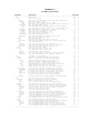
LIST OF FIGURES
1
P8 Main Menu Screen............................................ 5
2
P8 Device Types................................................ 8
3
P8 Mass-Balance Schematic...................................... 9
4
Schematic Diagrams - P8 Test Cases.............................13
5
Effect of Time of Concentration on Watershed Response..........19
6
Effects of Macrophytes on Wet Pond Removal Efficiencies........28
7
Comparison of Predicted Volume Capture Efficiencies............35
8
Comparison of Predicted Volume Capture Efficiencies - Great
Lakes Precipitation Sequence...................................36
9
Comparison of Predicted Suspended Solids Removal Efficiencies
for Wet Detention Ponds........................................37
10
Predicted Suspended Solids Removal Efficiencies vs. Particle
Class..........................................................38
11
Comparison of Predicted Phosphorus Removal Efficiencies........40
12
P8 Application to Hunt-Potowomut Watershed.....................47
13
Predicted and Observed Flows - Hunt-Potowomut River Calibration Period.............................................48
14
Predicted Instantaneous Peak Flow - Hunt-Potowomut River.......49
15
Predicted and Observed Flows - Hunt-Potowomut River Verification Period............................................50
16
Observed and Predicted Mean Daily Flows........................51
17
Observed and Predicted Monthly Total Streamflow................52
18
Observed and Predicted 12-Month Moving-Average Streamflow......53
19
Yearly Precipitation and Runoff TSS Concentration..............55
20
Longterm Average Removal Efficiencies for Dissolved Species,
Fine Particles, and Total Suspended Solids.....................56
21
Yearly Variations in TSS and Fine Particle Removal Efficiency..58
22
Yearly Deviations from Longterm Average TSS Removal............59
LIST OF FIGURES (ct.)
23
Yearly Deviations from Longterm Average TSS Outflow
Concentration..................................................60
24
Device Relative Areas Required to Achieve 70% and 85% TSS
Removal........................................................62
25
Relationship between Suspended Solids Removal and Violations in
Copper Toxicity Criterion for Wet Ponds Treating Median NURP
Sites..........................................................65
26
Particle Settling Velocity vs. Diameter and Density............67
LIST OF TABLES
1
Mass Balance Terms.............................................27
2
Calibration of Particle Parameters.............................30
3
Calibrated Runoff Concentrations...............................32
4
Water Quality Criteria.........................................32
5
Input Values for Sensitivity Analysis..........................42
6
Sensitivity Analysis Results...................................43
7
Input Values for Hunt-Potowomut Watershed......................46
8
Performance of Devices Designed for 70% TSS Removal............63
9
Performance of Devices Designed for 85% TSS Removal............64
1.0 INTRODUCTION
1.1 Overview
P8 is a model for predicting the generation and transport of
stormwater
runoff
pollutants
in
urban
catchments.
Continuous
water-balance and mass-balance calculations are performed on a
user-defined system consisting of the following elements:
-
WATERSHEDS (nonpoint source areas)
DEVICES (runoff storage/treatment areas, BMP's)
PARTICLE CLASSES
WATER QUALITY COMPONENTS
Simulations are driven by continuous hourly rainfall and daily air
temperature time series.
The model has been developed for use by
engineers and planners in designing and evaluating runoff treatment
schemes for existing or proposed urban developments.
This report
documents the structure, calibration, testing, potential uses, and
limitations of the program.
P8 is short for "Program for Predicting Polluting Particle Passage
through Pits, Puddles & Ponds".
It consists primarily of algorithms
derived from other urban runoff models (e.g., SWMM, STORM, HSPF, D3RM, TR20). Unique features include:
(1) minimal requirements for site-specific input data, typically
available from drainage plans, soil surveys, and other local
sources;
(2) expression of input data in terms which should be familiar
to local engineers and planners who normally deal with
hydrologic aspects of urban developments;
(3) initial calibration of certain water-quality parameters
(particle settling velocities, particle buildup/washoff
parameters, particle contaminant contents) so that predicted
runoff concentrations correspond to median (50th percentile)
or extreme (90th percentile) values measured under the EPA's
Nationwide Urban Runoff Program (NURP, Athayede et al.,
1983); these parameters may be modified by the model users
with alternative bases for calibration;
(4) capability for simulating a variety of treatment devices,
including swales, buffer strips, detention ponds (dry, wet,
extended), flow splitters, infiltration basins (offline,
online);
(5) extensive user interface, including interactive operation,
spreadsheet-like menus, help screens, and high-resolution
color graphics.
The program runs on IBM-PC-compatible microcomputers. Computers equipped
with 80286 processors (AT-class or higher) and numeric coprocessors are
recommended.
1.2 Limitations of P8 and Other Urban Runoff Models
Results of the Nationwide Urban Runoff Program indicate that runoff
quality is highly variable from site-to-site and from storm-to-storm at a
given site (Athayede et al., 1983). The availability of calibration data
limits the accuracy and use of urban runoff water quality models (Huber,
1986). Site-specific runoff quality data sufficient for model calibration
purposes are generally not available to the engineer/planner, particularly
when dealing with future developments. By relying upon generalized data
sources for calibration of certain key parameters, this model does not
"solve" data availability problems, but it does provide a reasonable
starting point for calibration and a consistent frame of reference for
evaluating proposed developments with respect to compliance with local
treatment guidelines.
One important concept is that runoff model predictions are more
accurate in a relative sense than in an absolute sense (Huber, 1986). For
example, because it is independent of assumed runoff concentrations,
prediction of suspended solids removal efficiency in a detention pond is
likely to be more accurate than predictions of inflow or outflow
concentrations of suspended solids or other water quality components.
Removal efficiency depends upon the distribution of particle settling
velocities (as estimated from NURP studies; Driscoll, 1983; USEPA, 1986)
in relation to the hydraulic characteristics of the treatment device
(area, depth, overflow rate, hydraulic residence time).
These
relationships are simulated by the physically-based model.
Predicted
removal efficiencies are independent of assumed inflow concentrations,
which are highly variable from site-to-site.
Predictions of total suspended solids (TSS) removal efficiency are
useful for evaluating the adequacy of urban runoff water quality controls
proposed for a given development.
For example, the Rhode Island
Department of Environmental Management (1988) has proposed that BMP's in
new urban developments be designed to provide average TSS removal
efficiencies of 85% in "sensitive" areas (e.g., watersheds of water supply
reservoirs, coastal ponds) and 70% in "non-sensitive" areas.
P8 is
designed for evaluating site compliance with these guidelines or others
expressed in terms of a target removal efficiency for a specific particle
class or water quality component.
Because of data limitations and site-to-site variations in the
factors controlling runoff quality, absolute predictions generated by the
model (inflow and outflow concentrations, loadings, violation frequencies)
are more likely to deviate from actual conditions at a given site than are
relative predictions of removal efficiency. Conservative input values
(e.g., NURP 90th percentile concentrations) can be used to generate worstcase projections of contaminant concentrations and loadings, but these
values should be interpreted cautiously because they may considerably
over-estimate contaminant levels at specific sites.
The difficulties and potential errors associated with predicting
absolute values at a given site may not be large a problem in a planning
context, because it is generally impossible to evaluate the downstream
water quality implications of over-predicting or under-predicting
contaminant loadings from a specific development. Over a large number of
sites, absolute predictions based upon the NURP 50th percentiles are
expected to provide more accurate assessments, although significant
regional biases in absolute predictions may still exist. Calibration of
model parameters to regional runoff monitoring data should help to reduce
local biases.
Another limitation of this and other urban runoff models is that
water quality predictions are developed by assigning contaminant contents
(mg/kg) to particle fractions.
The only removal mechanisms directly
simulated by the model are sedimentation and filtration.
Filtration
occurs when water infiltrates into the soil. Biological and/or chemical
mechanisms for contaminant removal in treatment devices are not directly
considered.
Given adequate data, however, such mechanisms could be
considered to the extent that they can be represented by the kinetics
formulations included in the model (filtration, first-order settling,
first-order decay, second-order decay).
1.3 Intended Uses
Based upon the above considerations, the model is intended primarily
for making "relative" predictions:
(1) Evaluating site plans for compliance with treatment
objective, expressed in terms of removal efficiency for
total suspended solids or a single particle class.
(e.g.,70%, 85% TSS removal, RIDEM, 1988);
(2) In a design mode, selecting and sizing BMP's to achieve a
given treatment objective. The program automatically scales
BMP's to match user-defined watersheds, storm time series,
target particle class, and target removal efficiency.
These applications are insensitive to errors associated with predicting
untreated runoff water quality and are therefore more accurate than
predictions of concentrations or loads. Note that a treatment objective
(removal efficiency and particle class) must be defined by the user.
Section 8.0 discusses treatment objectives.
Secondary uses of the model are for making "absolute" predictions of
the following types:
(1) Predicting
runoff
frequencies;
water
quality,
loads,
(2) Predicting
water
quality
impacts
due
to
developments (e.g., upstream vs. downstream
existing vs. future changes);
violation
proposed
changes,
(3) Generating loads for driving receiving water quality models;
(4) Watershed-scale
zoning issues).
or
basin-scale
landuse
planning
(e.g.,
These applications are subject to greater error because of the high degree
of site-to-site and storm-to-storm variability associated with urban
runoff quality. Local calibration may reduce absolute prediction error,
but is rarely feasible.
2.0 PROGRAM MECHANICS
P8 runs on an IBM-PC or compatible microcomputer with 640K memory,
hard disk, and MS-DOS operating system. To speed computations, an AT
(80286 processor) or higher class with a numeric coprocessor is
recommended. The program and sample input files occupy approximately 1.2
megabytes of disk space.
An additional 1 megabyte of disk space is
recommended for working files (more for long simulations). Typical run
times are on the order of .4 to 3 minutes per device per year of storms
simulated for AT or higher class machines with numeric coprocessors.
The program is written in FORTRAN-77 and compiled using the Microsoft,
Inc. Version 5.0 optimizing compiler (emulator library).
Supporting
subroutine libraries (graphics, screen control, character manipulation)
include ASMUTIL2 and BUTILE from Impulse Engineering, San Francisco.
The structure and capabilities of the program are summarized in the
Appendices to this report:
APPENDIX
APPENDIX
APPENDIX
APPENDIX
A
B
C
D
-
Menu Structure
Data Entry Screens
Output Screens
Help Screen Index
Appendix E contains step-by-step procedures for installing the program,
running sample problems or "CASES", entering new cases, and using the
program for designing BMP's.
The program is operated from a MENU, which occurs in a blue box at
the top of the screen, as illustrated in Figure 1. The bottom portion of
the menu screen describes the current case. The menu provides access to
~120 program functions, as outlined in Appendix A. Major menu headings
include:
'Case'
'Run'
'List'
'Plot'
'Utilities'
'Help'
'Quit'
-
Enter, Edit, Read, List, or Save Input Data
Execute Model
List Output (Several Formats)
Plot Output (Several Formats)
Supplementary Functions
View Help Screens
End Session and Return to DOS
Operation is similar to a spreadsheet.
Cursor arrows can be used to
maneuver around the menu. A faster method is to enter the first letter
associated with the desired choice at each menu level (e.g., 'CEDI' 'Case Edit Device Index'). Press <F7> to get help on menu operation.
HELP SCREENS provide online documentation for the program. These are
accessed by pressing the HELP KEY <F1> from the main menu, edit screens,
or data-entry screens. To view a help screen for any procedure in the
main menu, move the cursor to that procedure and press <F1>. To view a
help screen for any output screen, press <F1> in response to screen hold
<H> prompt in lower left-hand corner.
In addition, help screens are
accessed from the 'Help' selection on the menu, or by running the
independent utility 'HELP.EXE' from DOS. These utilities permit the user
to view help screens in groups, organized by topic, or to search the help
file for all screens containing a user-defined phrase.
The program runs in either of two USER MODES, depending upon the
user's level of experience:
NOVICE MODE
ADVANCED MODE
The NOVICE MODE (default) provides access to basic program functions but
prevents access to supplementary functions which new users may find
relatively difficult to follow. The number of choices available from the
program menu is limited.
The ADVANCED MODE provides access to all
functions and options. At startup, the program is set to NOVICE MODE. To
change to ADVANCED MODE (or vice-versa), press <SHIFT><F1> keys
simultaneously from any location in the program menu. A message will
appear indicating the new mode. Press any key to continue. A symbol in
the lower right hand corner of the menu box indicates the user mode ((
( =
NOVICE MODE, ) = ADVANCED MODE). Appendix A indicates procedures which
are available in each mode.
3.0 MODEL INPUTS
Input data for each model application or "CASE" are specified on
input screens described in Appendix B.
Each CASE has the following
maximum dimensions:
24
24
5
10
WATERSHEDS
DEVICES
PARTICLE CLASSES
WATER QUALITY COMPONENTS
General features of these input groups are described below.
3.1 Watershed and Device Characteristics
WATERSHEDS are the sources of flow and particles simulated by the
program.
They are defined based upon factors controlling runoff and
particle export (total area, impervious fraction, depression storage, SCS
curve number for pervious areas, street-sweeping frequency). The model
simulates runoff from pervious and impervious surfaces and particle
buildup/washoff from impervious surfaces.
Watershed runoff and
percolation can be routed to specified DEVICES.
DEVICES provide collection, storage, and/or treatment of watershed
discharges. Devices are defined based upon factors controlling hydraulic
response and particle removal efficiency (elevation/area table and
elevation/discharge tables for up to three outlets (1 = infiltration, 2 =
normal outlet, 3 = overflow/spillway). Specific inputs vary with device
types, as illustrated in Figure 2:
1 = Detention Pond (Wet, Dry, Extended)
2 = Infiltration Basin (Online, Offline)
3
4
5
6
7
=
=
=
=
=
Swale/Buffer
(Overland Flow Area)
General (User-Defined Elev/Area/Outflow Table)
Pipe/Manhole (Collector with One Outlet)
Splitter (Collector with Two Outlets)
Aquifer (Approx. Groundwater Budget, Baseflow Calc.)
Routing from one device to another is accomplished by specifying
downstream device numbers for each outlet. A downstream device number of
0 is used to route flow and loads out of the system (to receiving waters).
The linkage of watersheds and devices is illustrated in Figure 3. The
program keeps track of volume and mass fluxes into and out of each device,
as well as changes in storage. Program output formats (tables, graphs)
summarize this information in various ways.
3.2 Particle and Water Quality Component Characteristics
PARTICLE CLASSES are defined based upon factors controlling watershed
export (accumulation/washoff parameters for impervious areas, fixed runoff
concentrations for pervious and/or impervious areas, street-sweeping
efficiency) and behavior in treatment devices (settling velocity, decay
rates, filtration efficiency).
WATER QUALITY COMPONENTS are defined based upon their weight
distributions across particle classes (mg/kg).
Three standards or
criteria may be specified for each water quality component. These can be
used to estimate violation frequencies, based upon comparison with the
frequency distributions of event-mean outflow concentration for any device
and storm sequence.
Default values for PARTICLE CLASSES and WATER QUALITY COMPONENTS are
provided, based upon calibration to "typical urban runoff" values measured
under the EPA's Nationwide Urban Runoff Program (Athayede et al, 1983).
The following WATER QUALITY COMPONENTS are considered in the default
calibrations: total suspended solids, total phosphorus, total Kjeldahl
nitrogen, lead, copper, zinc, hydrocarbons. Section 6.0 of this report
describes the default calibrations. They may be modified by the user to
reflect
site-specific
measurements
and/or
alternative
modeling
assumptions.
To load a particle/component input file from the main menu, type
'CRP' (Case Read Particles) and press <Enter>.
A list of available
particle files will appear. Use the cursor arrows or space bar to point
to desired file name, and press <Enter>. The following sample input files
containing particle and water quality component parameters are provided:
NURP50.PAR
distribution of particle settling velocities derived from NURP
studies (USEPA, 1986); component concentration calibrated to
NURP 50th percentile (median) sites (Athayede et al, 1983).
NURP90.PAR
same as NURP50.PAR, except component concentrations calibrated
to NURP 90th percentile sites; these will generally predict
runoff concentrations which are 2-3 times higher than those
predicted by NURP50.PAR.
SIMPLE.PAR
a simple case (one particle class = NURP 10th percentile setting
velocity) for preliminary runs; requires less run time than
other files, which include five particle classes; runoff
treatment criteria may be based upon a single particle class
(See Section 8.0).
BARESOIL.PAR
NURP50.PAR with pervious runoff parameters adjusted to give TSS
concentrations typical of runoff from construction sites (~10,000
ppm, Schueler, 1987).
Any additional particle input files are listed and described in the
'PARTIC.DOC' file contained on the distribution disk.
3.3 Precipitation and Air Temperature
The distribution diskette contains precipitation and air temperature
measurements from Providence Airport. Runoff simulations are driven by
hourly precipitation time series, summarized on a storm-event basis. A
routine is provided to convert hourly precipitation files available from
the National Climatic Data Center for any NOAA Weather Station into the
appropriate format. There is no limit (except for disk storage capacity)
on the length of rainfall files.
Longer files and larger cases will
naturally require more computer time.
The following input files containing storm event sequences for use
with the model are provided:
PROV##.STM
yearly file from Providence Airport
## = year
type (see Section 7.4)
= 65, 81
"dry years"
= 74, 76, 80 "average years"
= 79, 83
"wet years"
= 6987
1969 thru 1987
TYPE2.STM
24-hour, SCS Type 2 Storm, 1-inch, 75-hr interval
Longterm average TSS removal efficiencies can be estimated by running
this storm file (see Section 7.4).
AVERAGE.STM
one average storm, .4 inches, 6-hr duration, 75-hr interval
The desired file name is entered in the first case input screen; from the
main menu, type 'CEF' (Case Edit First).
Any additional storm input
files are listed and described in the 'STORMS.DOC' file contained on the
distribution diskette.
Before starting a simulation, model state variables (particle buildup
on impervious watershed surfaces, device storage volumes, device
concentrations) are initialized. In order to purge effects of initial
conditions, it is necessary to run the model for a number of storms before
saving results. This is done by specifying the following dates on the
first 'CEF' input screen:
START DATE (YYMMDD format)
KEEP DATE
"
STOP DATE
"
The storm file 'PROV6987.STM' can be specified for simulating any date
interval between 1969 and 1987, inclusive. The model skips storms in the
specified storm file until the START DATE is encountered, at which point
the simulation begins. If the START DATE = 0, simulation begins with the
first storm contained in the storm file.
Simulation continues (but
without saving results) until the specified KEEP DATE is encountered, on
and after which results are saved.
If KEEP DATE = 0, all simulation
results are saved.
The simulation continues until the STOP DATE is
encountered, or until the end of the storm file, whichever occurs first.
The minimum duration of the startup period (KEEP DATE - START DATE)
depends upon the storage or "memory" of the devices included in the
simulation. A month is usually more than adequate for simulating runoff
treatment devices. Cases involving aquifers or other devices with long
times of concentration would require longer warmup periods to flush out
initial conditions (at least >= time of concentration). When in doubt,
sensitivity to startup period can be investigated on a case-by-case basis
(e.g., compare removal efficiencies computed with 1-month vs. 2-month
startup period for same KEEP and STOP DATES).
As alternatives to real rainfall sequences, single 'design storms'
can also be simulated. These are defined based upon an hourly rainfall
sequence, followed by a specified dry-weather period.
Examples are
'TYPE2.STM' and 'AVERAGE.STM'. When using a design storm, set the START
DATE, KEEP DATE, and KEEP DATE to 0. To purge initial conditions, the
design storm can be repeated for a specified NUMBER OF PASSES. Results
are saved only on the last PASS. Five PASSES are usually adequate for
simulating runoff treatment schemes using TYPE2.STM (1-inch, 24-hr storm
with 51-hour dry-weather period). Effects of alternative PASSES can be
easily checked by adjusting the input value and re-running the model.
Air temperature data are required only if the device network includes
an AQUIFER (TYPE=7) for simulation of baseflow. The daily air temperature
record for Providence Airport between 1969 and 1988 is contained in the
file 'PROV6988.TMP'. This file is specified on the evapotranspiration
input screen ('CEE' = 'Case Edit Evapotrans'). Specification of daily air
temperature data is transparent to the model user, as long as storm dates
between 1969 and 1988 are simulated. If storm dates are outside of this
range or if the air temperature file is not specified, longterm monthly
mean air temperatures are used, as defined on the evapotranspiration input
screen.
3.4 Sample Case Files
The program distribution disk contains a number of sample input files
which illustrate various model applications and can serve as templates for
building new applications. The 'CASES.DOC' file contains an updated list
and description of sample cases.
Running sample cases is recommended
before attempting to define and enter new cases. To load a sample case
file from the main menu, type 'CRA' ('Case Read All'), press <Enter>, use
cursor or space bar to point to desired input file, and press <Enter>.
Sample input files describe simple cases for program demonstration
purposes:
DEFAULT.CAS
simple case for preliminary testing one watershed, one device
(wet pond), one particle class; automatically read when program
is first loaded.
TEST.CAS
illustrates each type of treatment device; many devices are run
simultaneously in parallel; each device has same watershed
characteristics
The following case input files describe actual stormwater control systems
under design/operation in New England:
TRACER.CAS
One Tracer Lane Development, Lexington, MA
Offline Infiltration Basin, Detention Pond in Series
ESM_L.CAS
Emerald Square Mall, N. Attleborough, MA
Lower Watershed
2 Detention Ponds, Swale, 3 Wetland Cells in Series
ESM_U.CAS
Emerald Square Mall, N. Attleborough, MA
Upper Watershed
Detention Pond, 3 Wetland Cells in Series
HUNT.CAS
Hunt-Potowomut River, Narragansett Bay, RI
Watershed-Scale Application, with Baseflow Simulation
Schematic diagrams for selected cases are shown in Figures 4.
3.5 Entering New Cases
Appendix E outlines recommended procedures for defining and entering
a new case. The process is facilitated by first constructing a schematic
diagram of the site which illustrates the linkage of watersheds and
treatment devices (similar to diagrams used in TR-20 applications).
Appendix B illustrates the screens which are used to enter or edit data.
Help screens designed to assist the user in estimating various input
values (curve numbers, infiltration rates, etc.) are also printed in
Appendix B. Data entry/editing is performed using the following commands:
COMMAND
CEF
CEDI
CEDD
CEWI
CEWD
DATA GROUP
Case Title & Storm File
Device Index
Device Data (Separate Screen for Each Device Type)
Watershed Index
Watershed Data (Separate Screen for Each Watershed)
CEE
CET
CEP
CECF
Evapotranspiration Parameters (Optional)
Simulation Time Steps
Particle Characteristics
Water Quality Components
Editing of particle and water quality component input data is permitted
only in the program's ADVANCED USER MODE; press <Shift-F1> to switch user
modes.
A HELP SCREEN (shown on the bottom of each page in Appendix B)
provides online documentation for each data entry screen. Help screens
are accessed by pressing <F1>.
In addition, a one-line help message
appears at the bottom center of each data-entry screen and refers to the
current cursor location. More detailed help on certain data input values
(e.g., infiltration rates, Curve Numbers, Manning's n) are accessed by
pressing <F8> when pointing to the input field on a data-entry screen.
Some input fields are checked for valid ranges and warning messages are
flashed accordingly. To access the program's general HELP utility from a
data entry screen, press <F9>.
Input data can be listed using the 'CLS' (= Case List Site) command,
stored in a disk file using 'CSI' (= Case Save Inputs), and subsequently
retrieved using 'CRA' (= Case Read All).
In order to track results for each time step, devices must be TRACED.
Trace switches are set using the 'UT' = 'Utilities Trace' command
(ADVANCED USER MODE). Tracing is not required unless plotting of withinevent variations or daily-average values is desired.
Since tracing
consumes disk space and computer time, devices should be traced only when
necessary.
Once the input data have been entered for a given case, the model
must be executed via the 'RM' (= 'Run Model') command. Input values are
checked for validity and error messages (if any) are issued. The sequence
of storms is tracked on the screen until the simulation is completed. A
red message 'MODEL EXECUTED' appears in the lower right corner of the menu
screen to indicate that the simulation is complete.
When the model is executed for a given set of input values and storm
sequence, results are saved in temporary disk files for subsequent use by
listing and plotting routines. Stored values normally include event total
flows and loads for each device, particle class, and mass-balance term.
Output routines (tables, graphs) are accessible from the menu as long as
the "MODEL EXECUTED" message appears. This message disappears when input
values are edited or when a new case is loaded from disk.
To store output values on disk for later retrieval and review, use
the 'Case Save Archive' command. This saves both the input and the output
values for the current case. Use 'Case Save Inputs' to save input values
only.
The archive format consumes more disk space but permits future
review of output without re-running the simulation.
4.0 MODEL OUTPUTS
4.1 Simulation Results
Simulation results are stored in temporary disk files for access by
reporting and graphing routines.
Tabular output formats include the
following:
BALANCES - water and mass balances by device and component
REMOVALS - removal efficiencies by device and component
TERMS - comparison of flow, loads, and concs. across devices
VIOLATIONS - violation frequencies for event-mean concentrations
PEAKS - elevation and outflow ranges for each device
SEDIM - sediment accumulation rates by device
MEANS - mean inflow or outflow concs by device and component
DETAILS - detailed statistical summaries by device and component
CONTINUITY - continuity (mass-balance) check on simulation results
Tabular output may be displayed on the screen or routed to a disk file for
subsequent printing or other use (see 'UO' = 'Utilities Output').
Graphic output (to screen only) is available in the following
formats:
EVENTS
precip., flows, loads, concs., etc., in 5 formats:
time series
cumulative time series (running totals)
cumulative frequency distributions
lognormal frequency plots
scatter plots
DAILY
time series of daily total precip., volumes, or flows
(available for TRACED devices only)
MONTHLY
time series of monthly total precip., flows, or loads
YEARLY
time series of yearly total precip., flows, or loads
TRACED
detailed time series of precipitation, elevation, volume,
discharge, concentrations, or loads for specific devices.
Independent screen-dump utilities may be used to print screen displays.
(See 'Help - Program Operation - Printing Graphs' for a list of such
utilities). Plot data may be dumped to disk in ASCII format convenient
for input to spreadsheets or word processors (Press "d" when viewing
graphic screen). Graphic routines have been developed primarily for use
in model development and testing. Advanced users will find these routines
helpful for developing an understanding of the hydraulic and water quality
dynamics of individual cases. Graphic routines are accessible only in the
ADVANCED USER MODE <Shift-F1>.
Appendix C illustrates tabular and graphic output formats.
Help
screens associated with each output screen (shown on the right in Appendix
C) and are accessed by pressing <F1> in response to the screen hold prompt
<H> which appears in the lower left hand corner of the screen. Aside from
holding the screen and providing help access, the <H> prompt provides a
way of stopping execution of a current procedure. Some output procedures
produce several screens in series; to stop the output sequence and return
to menu, press <Esc> when the <H> prompt occurs. In general, the <Esc>
key (sometimes hit more than once) provides the fastest route back to the
program menu.
4.2 Design Functions
The model can be used in a "design mode" to select and size devices
appropriate for treating runoff from specified watershed(s). Appendix E
contains step-by-step procedures for using the program in a design mode.
One procedure ('RDL' = 'Run Design Lookup') selects and sizes a
device to achieve ~70% or ~85% total suspended solids removal for one
user-defined watershed. To use this routine, a valid case with at least
one watershed and one device must be pre-defined.
The program disk
contains a catalogue of devices sized to achieve total suspended solids
removal efficiencies of 70% and 85%, based upon simulation of Providence
1980 rainfall data (see Sections 7.4 and 8.0, Figure 24, Tables 8-9).
Devices are defined based upon type (wetpond, buffer, etc.) and other
factors determining TSS removal (mean depth, flood pool drawdown time,
infiltration rate, etc.).
The user specifies the watershed to be treated, the device prototype,
and the location (device number) for the new device (overwrites any predefined device). To size the device for the specified watershed, device
areas and volumes are rescaled based upon ratio of device area to
impervious watershed area. This represents an "initial guess" of design
requirements for a particular watershed, device type, and TSS removal
objective. This design can be modified to suit site characteristics and
constraints. Performance can be estimated using the 'RM' (= Run Model)
command.
Another procedure ('RDT' = 'Run Design Tune') tunes or rescales
device(s) to achieve a user-defined removal efficiency for any particle
class or water quality component. In order to use this procedure, the
user must first define a case containing a preliminary design and execute
it via the 'Run Model' command. The user is prompted for the list of
devices to be rescaled, target particle class, and target removal
efficiency.
Rescaling options include areas, volumes, and outlet
capacities (for detention ponds only). The model is run repeatedly using
the specified storm sequence. An iterative solution is attempted for the
device SCALE FACTOR, using the Newton-Raphson technique (Burden et al.,
1981). Device dimensions are multiplied by the SCALE FACTOR to achieve
the target removal efficiency. Solutions are not always feasible. A
maximum of 12 iterations is performed.
4.3 Sensitivity Analysis
Another procedure ('RS' = 'Run Sensitivity') tests sensitivity of
removal efficiency and device outflow concentration to each model input
value. Each input value is increased by a fixed percentage (one at a
time).
The model is re-executed.
Effects on removal efficiency and
outflow concentration are tabulated.
Tested inputs include watershed
variables, device variables, particle parameters, and storm scale factors.
This procedure is especially useful for obtaining perspectives on which
model inputs have the greatest impact on model predictions and are
therefore most important to estimate accurately (Walker, 1982).
Calculations may be lengthy; overnight computer runs may be convenient.
Trial runs on short storm sequences are recommended. The procedure can be
stopped at any time by pressing <Esc>.
Because it has a maximum feasible value of 100, the SCS curve number
(used for predicting runoff from pervious watersheds) is treated
differently than other input values in the sensitivity analysis. Instead
of increasing the curve number by 25% (which may lead to curve numbers
exceeding 100), the corresponding value for the maximum soil moisture
retention (= 1000/CN-10, inches, USDA/SCS(1964)) is decreased by 25%.
4.4 Flow Calibration
Calibration of the model to predict measured daily flow time series
is facilitated by the 'RC' (= 'Run Calibrate') command. This procedure
compares predicted daily-mean outflow time series from a specified device
with measured values contained in a disk file. Observed flow data are
stored in free-format, ASCII files, one line per month (example =
'HUNT.FLO'). The model must be executed beforehand ('RM' command) and the
device used in the calibration must be traced in order to obtain daily
output values ('UT' = 'Utilities Trace' command).
The program merges
observed and predicted daily flows by date.
Moving averages are
calculated at a user-defined interval. Observed and predicted time series
are plotted and compared statistically.
Flow calibration typically
involves adjusting times of concentration (for surface runoff and
baseflow) to match observed time series for short (1-day) and long (e.g.
30-day) averaging intervals. Application to the Hunt-Potowomut watershed
is described in Section 7.3. This procedure is not relevant to designing
BMP's for individual developments.
5.0 SIMULATION METHODS
5.1 Watershed Runoff Volumes
Runoff from pervious areas is computed using the SCS curve number
technique (USDA,1964). Haith and Shoemaker (1987) demonstrate use of the
SCS method for continuous watershed simulations.
Antecedent moisture
conditions (AMC's) are adjusted based upon 5-day antecedent precipitation
and season. In calculating AMC's, the "growing season" is assumed to
extend from May through October (Haith and Shoemaker,1987).
Although several other techniques are available for predicting runoff
from pervious areas (Huber and Dikinson,1988; Donigian et al., 1984), the
SCS technique has been selected because it is easily parameterized in
terms which are familiar to the planner/engineer (Curve Numbers). The
model is designed primarily for use in urban watersheds, where impervious
surfaces are the primary sources of runoff and contaminant load. Since
pervious and impervious areas are modeled separately, curve numbers refer
to the pervious portion of the site only (reflecting soil types and
vegetative cover, not impervious area!).
Use of SCS tabulated curve
numbers for urban land uses in P8 will result in double-counting of
impervious areas and will overpredict runoff volumes. A help screen is
provided to facilitate estimation of curve numbers (press <F8> when
pointing to Curve Number input field on data entry screen, or see 'Help Site Parameter Estimation'). Pervious portions of urban watersheds may
suffer from compaction; curve numbers should be estimated conservatively
(on the high side).
Percolation from pervious areas is estimated by difference (rainfall
- runoff - evapotranspiration).
Percolation is not tracked unless
explicitly routed to an "AQUIFER" (Device Type = 7), which can be used to
predict stream baseflow.
Evapotranspiration is computed from air
temperature and season using Hamon's (1961) method, as implemented by
Haith and Shoemaker (1987). Air temperatures can be specified on a daily
basis (linked by date to rainfall sequence) or on a longterm monthlyaverage basis (as entered via the 'Case Edit Evapotrans' input screen).
Both daily and monthly air temperature data from Providence Airport are
supplied with the program (Section 3.3).
Specification of air
temperatures and routing of percolation are relevant only if the device
network contains an AQUIFER and predictions of baseflow are desired.
Runoff from impervious areas starts after the cumulative storm
rainfall exceeds the specified depression storage. Thereafter, runoff
rate equals rainfall intensity.
All precipitation is assumed to be
rainfall.
Consideration of snowfall and snowmelt is recommended for
future versions of the program. A help screen is provided to facilitate
estimation of watershed impervious fraction based upon land use.
Watershed runoff is transported directly to downstream devices
(without lag). This assumes that the watershed time of concentration is
small in relation to the rainfall time step (1 hr), generally the case for
individual urban developments. Large watersheds will respond more slowly
than predicted. To retard watershed responses, runoff can be routed to a
"pipe" (Device Type = 5) with a positive time of concentration. Figure 5
shows watershed responses for various times of concentration. Putting two
or more pipes in series will impose a delay on the response (in addition
to decreasing peak flow). Sensitivity analyses (Section 7.2) indicate
that BMP removal efficiencies are usually insensitive to watershed time of
concentration. Note that lags or delays in storm hydrographs which are
caused by storage in upstream devices (e.g., detention ponds) are
simulated by the model.
5.2 Watershed Loads
Particle concentrations in runoff from pervious areas are computed
using the following empirical equation:
Cp =
Cpo If
where,
Cp = particle concentration in pervious runoff (ppm)
Cpo = concentration at a runoff intensity of 1 inch/hr (ppm)
I
= runoff intensity from pervious area (in/hr)
f
= exponent (~1)
This is similar to the sediment rating model included in SWMM (Huber and
Dikinson, 1988). Based upon typical sediment rating curves for rivers,
values of the exponent (f) range from 0.1 to 1.6, with most values near
1.0 (Huber and Dikinson, 1988). If percolation from pervious areas is
routed to an aquifer (Device Type= 7), concentration in percolating flow
is assigned to the runoff concentration (Cp), reduced based upon the
"filtration efficiency" defined for each particle class (Section 6.3).
Particle
techniques:
loads
from
impervious
areas
are
computed
using
two
Either or both of these methods may be used; results are totaled.
first method is used in default particle data sets.
The
(1) particle accumulation and washoff
(2) fixed runoff concentration
The following differential equation describes the simulation of
particle buildup and washoff on impervious surfaces, as implemented by the
model:
d B
----d t
=
L
- k B
- f s B -
a rc
B
where,
B = buildup or accumulation on impervious surface (lbs/acre)
L = rate of deposition (lbs/acre-hr)
k = rate of decay due to non-runoff processes (1/hr)
s = rate of street sweeping
(passes per hr)
f = efficiency of street sweeping (fraction removed per pass)
a = washoff coefficient
c = washoff exponent
r = runoff intensity from impervious surfaces
(in/hr)
The exponential washoff relationship is similar to that employed in EPA's
Stormwater Management Model (SWMM, Huber and Dikinson, 1988).
The
parameters "a" and "c" are analogous to SWMM's "RCOEFX" and "WASHPO",
respectively. Values are updated using the analytical solution of this
equation for each time step. At the start of the simulation, B values are
set equal to one day's worth of deposition.
Computed loads from pervious and impervious areas are multiplied by
a constant "Pollutant Load Factor" specified for each watershed. This
factor (normally = 1) can be used to adjust for differences in loading
intensity due to land use, for example, if sufficient calibration data are
available.
The load factor can also be adjusted to account for areas
which are not expected to contribute contaminants (e.g., = 0 for a
'watershed' representing the surface of a pond).
5.3 Device Flows
When the model is executed (via the 'RM' = 'Run Model' command), the
watershed/device network is first sorted in downstream order. If this is
impossible, the network contains feedback loops and a warning is issued.
An elevation/volume/discharge table is calculated for each device based
upon input information. This information is entered directly by the user
in the case of a General Device (Type=4). The table directs flow-balance
calculations using methods described below.
Flow and mass routing is performed in downstream order. For each
device and outlet, the relationship between storage volume and outflow is
represented by the following linear approximation:
Q
=
d0 + d1 V
where,
Q
= outflow for a given device and outlet
V
= current device volume
(ac-ft)
(ac-ft)
do = intercept of outflow vs. storage volume curve
(ac-ft/hr)
d1 = slope of outflow vs. storage volume curve
(1/hr)
Values of d0 and d1 are updated at each time step, based upon interpolation
from the elevation/area/volume/outflow table developed for each device.
Linearization of the storage/outflow relationship in the above manner
permits analytical solution of the device flow balance at each time step:
d V
--d t
=
Qin - SUM [ Q ]
The analytical solution for volume increase is as follows:
V2 - V1 = F(V,t)
=
A/K + (V1 - A/K) exp(- K t) - V1
A
= Qin - SUM [ d0 ]
K
= SUM [ d1 ]
where,
V1, V2
Qin =
= volume at start and end of time step (ac-ft)
total inflows to device; from watersheds and upstream
devices (ac-ft/hr)
SUM = sum over device outlets (infiltration, normal, spillway)
t = time step length (hours)
Since the slope and intercept (d1 & d0) may vary with volume and elevation,
a three-stage procedure is used to estimate the volume change at each time
step. The following calculations are performed in sequence:
Vm = V1 + .5 F(V1,t)
V2 = V1 +
F(Vm,t)
Vm = (V1 + V2)/2
V2 = V1 +
F(Vm,t)
Vm = ( V1 + V2 ) / 2.
where,
Vm = average volume during time step (ac-ft)
Device volumes are constrained to maximum values consistent with input
data specifications. Excess inflows are discharged through the "spillway"
(Outlet Number 3).
Device areas and elevations are updated by
interpolating against Vm in the elevation/area/discharge table.
Continuous water-balance and mass-balance checks are maintained on
each device and on the overall device network.
A warning message is
issued if continuity errors exceed the maximum value specified on the
timestep input screen ('Case Edit Timesteps'). Continuity errors can be
reduced by specifying shorter simulation time steps. Continuity errors
are more likely for devices with large, rapid fluctuations in volume
(e.g., buffers/swales). Typical time step lengths are .25-1 hours during
storm periods and 2-8 hours for dry periods for volume continuity errors
less than 2%. Sensitivity of device performance to time step lengths can
be tested by adjusting lengths and re-running the model.
5.4 Device Outlet Capacities
Manning's equation (Bedient and Huber, 1988) is used for predicting
flow velocities in overland flow areas (buffers/swales, device type = 3):
u
= 1.49 r2/3 s1/2 / n
where,
u = overland flow velocity (ft/sec)
r = hydraulic radius = cross-section/wetted perimeter (ft)
s = slope (ft/ft)
n = Manning's n
A trapezoidal geometry is assumed for calculating the hydraulic radius at
any elevation, based upon input buffer dimensions (bottom width, side
slope, maximum depth).
The maximum depth of overland flow (input variable) is defined as the
maximum depth at which the specified value of Manning's n applies.
According to TR-55 (USDA/SCS, 1985), this value is on the order of .1
feet. High values of n typically used for grassed areas (.2-.4) assume
that flow is in contact with the vegetation. The specified maximum depth
should not exceed the effective vegetation height. The model constrains
buffer flow depth to the specified maximum value.
If this depth is
reached, routing based upon Manning's equation stops and excess inflows
are forced through the device at a fixed water depth and hydraulic crosssection.
This procedure is conservative with respect to predicting
overland flow velocities because flow depths would actually continue to
increase, but be governed by lower n values. Model testing indicates that
predicted particle removal efficiencies are generally insensitive to the
specified maximum depth of overland flow. Predicted peak flow velocities
(for comparison with erosion/scouring criteria, typically ~4 ft/sec, RIDEM
(1988)) can be sensitive to maximum flow depth, however, and are likely to
be conservative (over-estimated).
Future investigation of alternative
procedures for handling high flow depths in buffers (including direct
simulation of particle scouring) is recommended.
Detention pond (type=1) outlet capacities are calculated from input
dimensions using standard hydraulic formulae for weirs and orifices
Bedient and Huber, 1988):
qw = cw lw h1.5
qo = co ao (2 g h)1/2
where,
qw = weir flow (cfs)
cw = weir coefficient ~ 3.33
lw = weir length (ft)
h
= height above weir crest or above orifice centerline (ft)
qo = orifice flow (cfs)
co = orifice coefficient ~ .6
ao = orifice area (ft2)
g
= acceleration of gravity = 32.2 ft/sec2
Outlet dimensions (orifice diameter, weir length) and discharge
coefficients are supplied on the data-entry screen for detention ponds
(see Appendix B). If flood pool drawdown time is input directly (based,
for example, upon output from TR-20 or other flood routing model), the
assumed shape of the drawdown curve is similar to that obtained for a
weir. Vertical perforated risers are assumed to consist of a number of
holes (orifices) of a given diameter distributed uniformly over the
specified riser height. The orifice discharge coefficient (co) is also
used for computing riser flows.
Only one controlled outlet can be specified for the flood pool of a
detention pond (orifice, weir, riser, or direct input of drawdown time).
The is referenced as the "normal" outlet (see Figures 2 and 3). When the
flood pool of a detention pond is full, the pond elevation is fixed and
the "spillway" outlet is activated to pass excess overflows. In the case
of a wet detention pond with no flood storage, the "normal outlet" is not
used and all outflows occur through the "spillway". User's should take
care to assign appropriate device numbers to each detention pond outlet.
Ponds with more complex designs (multiple outlets at different elevations)
can be handled by defining them as "general" devices (type=4); this
requires direct entry of the elevation/area/discharge table.
Such
information is often available from TR-20 input or output tables.
5.5 Device Concentrations
Each device is assumed to be completely mixed for the purposes of
computing concentrations and outflow loads. The following equations are
solved:
d M
--d t
D
=
=
W -
D M
Q/Vm + f K1 + f K2 Cm
+ f U Am/Vm
Analytical Solution:
M2
= W/D + (M1 - W/D) exp(-D t),
= M1 + W t
,
if D > 0
if D = 0
where:
D
= sum of first-order loss terms
(1/hr)
Cm = average concentration during step (ppm)
Vm
= average device volume during time step
(ac-ft)
M1,M2 = particle mass in device at start and end of time step (ac-ft*ppm)
t = time step length (hours)
W
= total inflow load to device, from watersheds and upstream devices
(ac-ft*ppm/hr)
Q
= average outflow from device, from flow balance (ac-ft/hr)
U
= particle settling velocity (ft/hr)
Am = average device surface area during time step (acres)
K1 = first-order decay coefficient (1/hr)
K2 = second-order decay coefficient (1/hr-ppm)
f
= particle removal scale factor, device-specific
The solution technique is similar to that used in the SWMM Transport Block
(Huber & Dikinson, 1988), except it is based upon mass rather than
concentration. Concentrations are computed as follows:
C2
=
M2/V2
Cm
=
[ W + (M1 - M2)/t ]
Vm / D
(from mass balance)
where,
C2 = concentration at end of time step (ppm)
V2 = volume at end of time step (ac-ft)
Cm = average concentration during time step, used for routing outflows
to downstream devices (ppm)
If a nonzero 2nd-order decay rate (K2) is specified, three iterations are
performed, updating the first-order loss term (D) each time based upon the
average concentration (Cm) computed in the previous iteration.
Depending upon device type, up to 15 mass-balance terms are
considered in the simulations, as identified in Table 1 and Figure 3. The
following mass-balance equations apply to simulations of volume and
particle mass in each treatment device:
Inflows = Outflows + Incr.-in-Storage + Removals + Continuity Error
Inflows = Watershed Disch. + Inflows from Upstream Devices
Outflows = Infiltration + Normal Outlet + Spillway
Increase-in-Storage = Final Storage - Initial Storage
Removals = Sedimentation + Decay + Filtration
5.6 Particle Removal Scale Factors
Using the above equations and parameter estimates discussed in the
next section, the model simulates the inflow, removal, and outflow of
particles in devices. Calibrated particle settling velocities are based
upon settling column tests conducted using urban runoff (Driscoll, 1983;
USEPA, 1986, see Section 6.1). Settling velocities may be modified in any
device by adjusting the 'Particle Removal Scale Factor', which is
specified on the input screen for each device type. This factor (usually
= 1) modifies settling velocities and decay rates specified on particle
input screens to account for device-specific characteristics.
One potentially important use of the 'Particle Removal Scale Factor'
is to account for effects aquatic vegetation in detention ponds and
wetlands. Theoretically, macrophytes can increase particle removal rates
under a given hydraulic regime by increasing the effective surface area
for settling (tray-settling concept), stabilizing bottom sediments, and/or
through biological mechanisms.
Design methodologies developed in
Australia account for a ~5-30%% increase in sediment and phosphorus
removal at a given hydraulic residence time in ponds with macrophytes vs.
ponds without macrophytes (Phillips & Goyen, 1987; Lawrence, 1986). Their
removal efficiency curves are consistent with scale factors of 2-3 for
suspended solids and 3-6 for total phosphorus attributed to macrophyte
presence in wet detention ponds (Figure 6). The effect of vegetation is
to shift the removal vs. residence time curves to the left, so that lower
residence times (and treatment areas) are sufficient to achieve the same
removal efficiency, as compared with ponds with similar hydraulic features
but without macrophytes.
Alternatively, removal scale factors less than 1.0 can be assumed to
account for poor hydraulic design (outlet next to inlet, promoting
short-circuiting of inflows). Such adjustments would have to be made on
a case-by-case basis, depending upon design characteristics and user
judgement. Such designs should be avoided.
6.0 MODEL CALIBRATION
The model can be calibrated to simulate contaminants with first-order
settling, first-order decay, and/or second-order decay kinetics. Several
approaches are feasible. The preliminary calibrations described below are
based upon NURP monitoring results for median and 90th percentile sites.
These calibrations (stored in data files 'NURP50.PAR' and 'NURP90.PAR',
respectively) provide initial frames of reference for users lacking sitespecific runoff water quality data. Sensitivity to particle parameter
values is in Section 7.2.
Additional testing and refinement of the
particle/water quality component calibrations are recommended for future
research.
6.1 Particle Classes
The following particle
files distributed with the
primarily upon calibration to
distributions measured under
Class
P0%
Description
Dissolved
classes are included in the particle input
program (NURP50.PAR and NURP90.PAR), based
runoff concentrations and settling velocity
the Nationwide Urban Runoff Program:
% of TSS
0
Settling Veloc.(ft/hr)
0
P10%
P30%
P50%
P80%
10th
30th
50th
80th
Percentile
Percentile
Percentile
Percentile
20
20
20
40
.03
.3
1.5
15
The first class permits consideration of dissolved (non-settling)
fractions of runoff water quality components. The remaining classes are
based upon NURP settling velocity distributions (Driscoll, 1983; USEPA,
1986). Other particle input parameters are described in Table 2.
Watershed buildup/washoff parameters have been calibrated to so that
median, event-mean TSS concentrations for both pervious and impervious
areas equal those reported under NURP (100 ppm for median site, 300 ppm
for 90th percentile site).
As a consequence of the particle
buildup/washoff dynamics, the predicted flow-weighted-mean concentration
of total suspended solids (used for computing annual load) is
approximately equal to the median, event-mean concentration (100 ppm for
median site).
Athayede et al. (1983) used a flow-weighted-mean
concentration of 180 ppm for computing annual loads from impervious areas.
This concentration was calculated by applying a factor of 1.8 to the
median, event-mean concentration. The factor accounts for the lognormal
distribution of event-mean concentrations (transformation from median to
arithmetic mean).
The adjustment assumes that concentration is
independent of runoff volume and ignores particle buildup/washoff
dynamics, which typically cause decreases in mean concentration at high
storm volumes ("first-flush" effect). The NURP mean TSS concentration of
180 ppm was not directly calibrated against runoff data.
The flow-weighted-mean TSS concentration of ~100 ppm predicted using
the parameter values in Table 2 is consistent with values reported by
Schueler (1987, p. A6) for ~19 urban watersheds in the Washington DC area
with drainage areas less than 100 acres (range ~20 to ~190 ppm, average
~75 ppm). Users wishing to make alternative assumptions regarding TSS (or
other contaminant) concentrations can do so by adjusting the appropriate
values. The easiest way to adjust runoff concentrations is by using the
'scale factors' on the water quality component input screens (Appendix B,
Procedure = 'CEC' = 'Case Edit Components'). For example, to assume a
mean runoff TSS concentration of 180 ppm (vs. 100 ppm), assign a value of
1.8 to the TSS scale factor (particle file = NURP50.PAR).
Computed
particle removal efficiencies will be insensitive to such adjustments.
6.2 Particle Composition
Particle compositions (mg/kg) are used to translate particle
concentrations into concentrations of total suspended solids, total
phosphorus, total Kjeldahl nitrogen, copper, lead, zinc, and hydrocarbons.
Compositions have been calibrated so that median, event-mean runoff
concentrations correspond to values reported by the Nationwide Urban
Runoff Program (Athayede et al., 1983), as listed in Table 3.
The
calibration is based upon simulation of 1983-1987 Providence Airport
rainfall. A high degree of site-to-site variability is reflected by the
2- to 3-fold differences between the NURP median and 90th percentile
sites. Because of this variability, specification of particle composition
and prediction of runoff concentrations at a given site are subject to
considerable uncertainty. Calibration of the model to local or regional
runoff data may help to reduce this uncertainty.
NURP lead EMC's (.144 ppm for median site, .350 ppm for 90th
percentile site) have been reduced to .02 and .05 ppm, respectively, to
account for the more than ten-fold reduction in the maximum lead content
of gasoline which occurred after NURP monitoring. A recent urban runoff
study in Minnesota (Oberts et al., 1989) reported annual, flow-weightedmean concentrations ranging from .004 to .027 ppm at 5 sites. Schueler
(1987) reported a median, event-mean concentration of .02 ppm for urban
runoff in Washington, DC.
Distribution of water quality components among particle classes is
based upon results of direct runoff measurements, settling column tests,
and typical pollutant removal efficiencies in treatment devices (see
Section 7.1). TSS concentration is computed as the sum of the individual
particle fractions. For lead and hydrocarbons, approximately 10% of the
total runoff concentration is assumed to be associated with the dissolved
class (P0%); the remainder is evenly distributed among the remaining
particle classes.
For total phosphorus, 30% of the total runoff
concentration is assumed to be associated with the dissolved particle
class (P0%). A dissolved fraction of 40% is assumed for total kjeldahl
nitrogen, copper, and zinc. Non-dissolved portions of total phosphorus,
Kjeldahl nitrogen, copper, and zinc are distributed equally among the
three smallest particle classes (P10%, P30%, P50%). Soluble fractions are
based partially upon results of runoff monitoring conducted under the NURP
Priority Pollutant Monitoring Project (Cole et al.,1983), settling column
tests (Whipple and Hunter, 1981), modelling studies by Driscoll (1983),
and removal efficiencies for wet ponds (Schueler, 1987, Figure 4.6).
Removal efficiencies for nutrients and heavy metals predicted with these
parameter values may be conservative because chemical and biochemical
mechanisms responsible for removal of dissolved fractions are not
considered.
A fundamentally different approach to simulating contaminant
partitioning and behavior in devices would assign each contaminant to a
separate particle class and use second-order decay kinetics (instead of
first-order settling). The effect of second-order kinetics is to slow
down the rate of removal as concentrations decrease. The same effect is
achieved in the above calibration by distributing each contaminant among
dissolved and particulate fractions with different setting velocities.
This partitioning is artificial because size fractions and effective
settling velocities are actually distributed continuously.
The
applicability of second-order decay kinetics has been demonstrated for
hydrocarbons in NURP settling column tests (Athayede et al., 1983, Volume
II), phosphorus removal in reservoirs and detention ponds (Walker, 1985,
1987), and TSS, phosphorus, and zinc removal in settling columns (author's
unpublished analysis of settling column data reported by Grizzard et al.,
1986).
Second-order kinetics are consistent with removal mechanisms
involving
particle interactions (e.g., flocculation), as opposed to
discrete settling.
Such processes may be very important in treatment
devices, as well as in receiving waters. Investigation of this modeling
approach is recommended for future work.
6.3 Filtration Efficiency
Filtration efficiency (percent of particle class removed when water
infiltrates a device or pervious watershed area) is assumed to be 100% for
each suspended solids fraction (P10% - P80%). A filtration efficiency of
90% is assumed for the dissolved fraction (P0%), to account for
adsorption, precipitation, and other reactions between dissolved runoff
contaminants and the soil matrix. Such reactions are responsible for the
generally low concentrations of phosphorus and heavy metals found in
groundwaters beneath runoff swales and retention basins (Wigington et al.,
1986; Youseff et al., 1986; Nightingale, 1987ab, Schiffer, 1988). The
effects of assuming alternative values for filtration efficiency can be
easily investigated by editing the filtration efficiency contained on the
particle input screen ('CEP' = 'Case Edit Particles').
With these parameter values, the predicted total phosphorus
concentrations in groundwater is ~.01 ppm (median runoff total P = .33
ppm, 30% dissolved, 90% removal of dissolved fraction upon infiltration),
which is typical of this region.
Predicted average streamflow total
phosphorus concentrations (baseflow + runoff) range from .014 to .15 ppm
for impervious fractions ranging from 0% to 25%. This range is similar to
that derived from regression analysis of average stream phosphorus
concentrations in 116 Northeastern watersheds sampled by the EPA National
Eutrophication Survey (Walker, 1978, 1982).
6.4 Water Quality Criteria
Water quality criteria included in the particle/component files
NURP50.PAR and NURP90.PAR are listed in Table 4.
The 'LV' (='List
Violations') procedure compares these values with the distribution of
event-mean concentrations for any device and mass-balance stream. Output
summarizes the percent of events in which the event-mean concentration
exceeds each of three criteria specified for each water quality component.
Criteria can be modified via the 'CEC' (= 'Case Edit Components')
procedure (ADVANCED USER MODE only).
The concept of using violation
frequencies for evaluating urban runoff impacts is discussed in the NURP
final report (Athayede et al., 1983). The lack of criteria which are
realistic for urban runoff situations (Mancini and Plummer, 1986) limits
the interpretation of violation frequencies and the extent to which they
can be properly used in the context of site planning, design, or impact
assessments. Predictions violation frequency are also uncertain because
of high site-to-site variations in runoff quality.
7.0 MODEL TESTING
7.1 Device Performance
As stated in the introduction, the program is intended primarily for
use in evaluating compliance with a treatment goal expressed in terms of
percentage removal for total suspended solids or a single particle class.
One method for testing the model is to compare predicted removal
efficiencies with predictions based upon other theoretical or empirical
models which have been tested against observed performance data (Driscoll,
1983; USEPA, 1986; Schueler, 1987; Walker, 1987).
Figures 7 and 8 compare simulated volume capture efficiencies for
infiltration basins with predictions of a probabilistic model developed by
Driscoll (USEPA, 1986). The curves relate volume capture efficiency to
ratio of basin area to watershed area for different regions, basin mean
depths, and infiltration rates. The simulations are based upon Providence
1983-1987 rainfall. Since Driscoll's methodology assumes a fixed runoff
coefficient, runoff from pervious areas is not included in the P8
simulations. Figure 8 is based upon typical precipitation patterns for
the Great Lakes area.
The Providence rainfall time series has been
adjusted to give the same mean storm volume and intensity used in the
Driscoll's simulations. Symbols on the lower graph in each figure show
Driscoll's predictions (extracted from upper graph) in relation to P8
predictions.
Agreement between the two methodologies for predicting
volume capture in infiltration basins is good.
Figure 9 compares simulated suspended solids removal efficiencies for
wet detention ponds with Driscoll's (1983; USEPA, 1986) results.
The
curves relate removal efficiency to the ratio of basin area to watershed
area for different regions of the country. To permit comparison of model
results for equivalent watershed dynamics, constant runoff coefficients
and constant runoff concentrations have been used in the P8 simulations.
Supplementary testing indicates that predicted removal efficiencies are
insensitive to washoff dynamics.
The settling velocity used in the
simulations is equivalent to that developed by Driscoll (1983), based upon
NURP data.
Predicted removal efficiencies in each particle class are
shown in Figure 10.
Figure 9 shows that while the methodologies agree on the average, P8
over-predicts Driscoll's results at low Ab/Aw and under-predicts Driscoll's
results at high Ab/Aw ratios.
As noted by Driscoll (1983), particle
removal under dynamic conditions occurs when the settling velocity exceeds
the basin overflow rate (ft/hr). The average basin overflow rate (outflow
per unit area) can be estimated as follows:
Qs
= Aw r I / 12 Ab
where,
Qs = average overflow rate (ft/hr)
Ab = basin surface area (acres)
Aw = watershed area (ac-ft)
r
= watershed runoff coefficient
I
= mean storm intensity (in/hr) ~.06 in/hr
For the lowest area ratio shown in Figure 9 (.01 %), the above expression
evaluates to 10 ft/hr, much less than the settling velocity of the largest
particle fraction (65 ft/hr), which is assumed to account for 20% of the
total suspended solids. When removal under quiescent conditions is also
considered, TSS removals in excess of 20% would be expected for Ab/Aw =
.01%, yet Driscoll's method predicts removals less than 10% (~5% for NE
rainfall).
At high Ab/Aw ratios, P8 under-predicts Driscoll's results by 5-10%.
Driscoll (1983) compared measured TSS removal efficiencies for NURP basins
with predictions of his model.
In a total of four cases, predicted
removal efficiencies exceeded 90%.
In each of these cases, however,
observed removals were ~6 to ~30% lower than model predictions. The fact
that P8 under-predicts results of Driscoll's model at high removal
efficiencies is consistent with observed performance data.
Walker (1987) showed that an empirical model originally developed for
predicting phosphorus retention in reservoirs (Walker, 1985) could be used
to predict phosphorus removal in urban runoff detention basins. Figure 11
compares phosphorus removal efficiencies computed by P8 with predictions
of the empirical model, based upon Providence 1983-1987 rainfall.
Saturation at high Ab/Aw ratios reflects assignment of 30% of the runoff
total phosphorus to the conservative particle class (P0%). Results are in
good agreement.
The above comparisons indicate that P8 predictions of removal
efficiency in infiltration basins and wet detention ponds are in
reasonable agreement with predictions derived from other models.
Additional testing of the model and refinement of the preliminary
calibration using regional monitoring data are recommended for future
work.
7.2 Sensitivity Analysis
Specification of model input values defining watershed, device,
particle, and storm characteristics is based partially upon direct
measurement, estimation, and the generalized calibrations discussed above.
The sensitivity analysis procedure ('Run Sensitivity') provides insights
into which input values have the greatest impact on computed removal
efficiencies and outflow concentrations.
This, in turn, helps to
prioritize inputs (and their inherent assumptions) with respect to their
importance. This procedure is demonstrated below for six device types
(pipe, wet pond, dry pond, extended pond, infiltration basin, and buffer
strip/swale) with identical watershed characteristics.
Using the 'Run Design Tune' procedure, each device was originally
sized to achieve 70% TSS removal for a 1-inch, 24-hour, Type-2 storm with
75-hour period between storm midpoints (storm file = 'TYPE2.STM'). Device
and watershed characteristics are given in Table 5. Input values are
stored in the file 'SENSIT.CAS' on the program distribution disk.
Simulations were then run using Providence rainfall time series for 1984
through 1986. Results from the 'Run Sensitivity' procedure are shown in
Table 6. Each input variable was increased by 25% (one at a time) and
impacts on TSS removal efficiency and flow-weighted-mean outflow
concentration were tabulated. Note that this type of calculation is time
consuming (~4 hours on an 80386/80387/20 mhz machine) because the entire
3-year simulation is repeated 38 times (once for each model input
variable).
Input variables are grouped in four categories: watershed, device,
particle, and storm. In typical applications, the first two groups are
specified by the model user and the last two groups are specified in the
default particle file ('NURP50.PAR') and storm data files. The following
points are based upon review of sensitivity analysis results in Table 6:
(1)
Removal efficiencies are much less sensitive to variations in
input values than are outflow concentrations.
For example,
changes in wet pond removal efficiencies range from -5.7% to
+1.7% for a 25% increase in input values. Corresponding changes
in outflow concentrations range from -14.5% to +25%. This
reflects the fact that variations in factors determining runoff
(inflow) concentrations are "canceled out" in computing removal
efficiencies. As discussed in Section 1.2, removal efficiencies
("relative predictions") are expected to be more accurate then
outflow concentrations or loads ("absolute predictions").
(2)
The 'washoff exponent' for impervious surfaces has a high
sensitivity ranking for removal efficiencies.
Reductions in
removal efficiency resulting from a 25% increase in this
parameter range from 2.7% to 6.6% for the various devices
(exclusive of 'pipe'). Sensitivity reflects the fact that this
parameter is an exponent (rather than a coefficient or linear
term). The value selected for this parameter (2.0) provides
intensity-dependent washoff, as included as an option in the
most recent version of SWMM (Huber and Dikinson, 1988). Early
versions of SWIM and other models (e.g., STORM) assumed a
washoff exponent of 1. The effect of a higher washoff exponent
is to attribute a higher portion of the annual washoff load to
intense storms, when device residence times and particle removal
efficiencies tend to be lower. In essence, use of a higher
washoff exponent (2 vs. 1) decreases the importance of firstflush responses over long storm time series. This will cause
conservative estimation of particle removal efficiencies below
watersheds which have strong first-flush responses.
(3)
Changes in removal efficiency resulting from a 25% increase in
particle settling velocities range from +1.7% to +2.4%.
Although settling velocity ranks high in relation to other input
values, the degree of sensitivity is low.
(4)
Removal efficiencies are more sensitive to storm volume (-3.1%
to -9.3%) than to storm duration (+.5% to +2.2%). This reflects
the fact that removals are more dependent upon the total runoff
volume (e.g., "quiescent removal", Vb/Vr relationships) than to
overflow rate during storm periods ("dynamic conditions",
Driscoll, 1983). Because it has the lowest effective storage
volume, the swale/buffer has the highest sensitivity to storm
duration (2.2% increase removal efficiency for a 25% increase in
storm duration).
The low sensitivity to storm duration (or
intensity) means that removal efficiencies will be insensitive
to errors in predicting the temporal distribution of runoff
flows and loads within storm events (e.g., time of
concentration, watershed lag).
7.3 Watershed-Scale Application
This section describes calibration and testing of the model against
measured streamflows in the Hunt-Potowomut watershed.
Watershed
characteristics derived from GIS data bases are summarized in Table 7.
Segmentation of the model to predict surface runoff and baseflow at the
mouth of the watershed is illustrated in Figure 12. An 'AQUIFER' device
is used to simulate baseflow and a 'PIPE' is used to collect surface
runoff. Outflows from these devices are routed to a second 'PIPE' for
prediction of total streamflow. The model has been calibrated against
streamflows measured by the USGS (Gauge 01117000) for Water Years 19811983 and tested against data for Water Years 1984-1986.
Calibration involves adjusting times of concentration for baseflow
and surface runoff to match observed peak flows over various averaging
intervals. Observations and predictions are compared using the 'RC' (=
'Run Calibrate') procedure, as illustrated in Figure 13. The baseflow
time of concentration (700 hours or ~ 30 days) has been calibrated against
the measured 30-day-moving-average peak flow for Water Years 1981-1983
(~230 cfs, April 1983). The 30-day-moving average is used for baseflow
calibration because it is insensitive to runoff time of concentration
(much shorter than 30 days). The surface runoff time of concentration (70
hours) has been calibrated against the instantaneous peak flow observed on
April 11, 1983 at 4:30 am (968 cfs). As shown in Figure 14, the model
accurately predicts both the magnitude and the time of this peak with the
calibrated times of concentration.
Results of model testing against measured daily streamflows for Water
Years 1984-1986 are shown in Figures 15 and 16. Observed and predicted
monthly total flows (expressed in inches over entire watershed) for the
entire period of flow record (Water Years 1970-1986) are compared in
Figure 17.
Yearly moving-average flows are compared in Figure 18. The
model over-predicts yearly-mean flows during drought periods (1971, 1977,
1981). This may be related to errors in the prediction of evapotranspiration or to the effects of diversion from the watershed for water
supply purposes (not considered in simulations). The USGS (1977) reports
that measured flows are affected by water supply diversions for East
Greenwich, North Kingstown, Warwick, and Quonset Point (magnitudes of
diversions not reported).
Such diversions would tend to have greater
impacts on measured streamflows during drought periods. Provision for
flow diversions into or out of watersheds is suggested for future versions
of the model; diversions would tend to be more important for simulation of
large watersheds, as compared with simulations of individual urban
developments.
The above comparisons support the structure and calibration of the
hydrologic components of the model for predicting streamflow. Calibration
and testing of water quality components against site-specific data (sitescale and watershed-scale) are recommended for future work.
7.4 Effects of Precipitation Variations
Climatologic variations influence the quantity and quality of
watershed runoff and the performance of runoff treatment devices.
This
section evaluates these variations using the entire precipitation record
from Providence Airport (1948-1988).
Results have implications for
selecting appropriate time periods for simulating device performance,
given the objective of estimating longterm means and/or extremes.
Figure 19 shows yearly variations in precipitation and flow-weightedmean total suspended solids concentration. Simulations are for a typical
urban watershed (25% impervious, pervious curve number = 74, NURP50.PAR
parameter
estimates).
An
inverse
relationship
between
annual
precipitation and mean TSS concentration is apparent.
This reflects
washoff dynamics inherent in the particle parameter estimates.
The simulated loads have been routed through five treatment devices,
each initially sized for 70% TSS removal from a 1-inch, 24-hour, SCS Type2 storm with a 75-hour time between storm midpoints. These are the same
devices used in the sensitivity analysis discussed in Section 7.2. Figure
20 shows predicted longterm average removal efficiencies for TSS, fine
particles (P10%), and dissolved species (P0%).
Removal of dissolved
species (filtration) occurs only in the infiltration basin and buffer
strip.
Longterm average TSS removal efficiencies range from 71.6%
(extended detention pond) to 78.9% (infiltration basin), as compared with
the 70% initial design basis. This indicates that the 1-inch, Type-2
storm provides a conservative basis for estimating longterm average TSS
removal efficiency, particularly for infiltration basins. The advantage
of using the 1-inch storm (in place of simulating the entire rainfall
record) is that it requires much less computer time. The 1-inch storm can
be used in preliminary design calculations to evaluate compliance with TSS
removal objectives. Final evaluations should be based upon simulation of
historical records (choice of time periods discussed below). Results are
relatively insensitive to intensity distribution within the storm (e.g.,
Type-2 vs. Type-3 vs. triangular).
The Type-2 distribution has been
selected arbitrarily.
Figure 21 shows yearly variations in TSS and fine particle (P10%)
removal in each device. The strong year-to-year covariance in these time
series reflects the influences of storm intensity and volume on device
performance. It is apparent from Figures 20 and 21 that devices sized to
achieve a given TSS removal objective will not necessarily have the same
removal efficiencies for fine particles (or dissolved species). The dry
pond and extended ponds, in particular, are considerably less effective
than the other devices at removing fine particles at a given TSS removal.
This is one important limitation of using TSS removal as the exclusive
design objective. It may be more desirable to target a specific particle
class. This limitation is discussed further in Section 8.0.
Figures 22 and 23 show yearly variations in TSS removal and outflow
TSS concentrations for each device, respectively. Values are expressed as
deviations from the 1948-1988 means. These plots can be used to identify
years in which predicted removal efficiencies and outflow quality are
similar to longterm averages. For years 1951, 1968, 1974, 1976, and 1980,
both removal efficiencies and outflow concentrations are within two units
(% or ppm) of the longterm mean for each device type. Results are similar
for individual particle fractions. Annual rainfall was also within 2inches of the longterm mean (43 in/yr) in 1951, 1968, and 1976. These
years are logical choices for evaluating BMP's, given the objective of
estimating the longterm-average removal efficiency or outflow quality.
"Worst-case" (wet) years would include 1955, 1979, and 1983.
(dry) years would include 1965 and 1981.
"Best-case"
8.0 TREATMENT CRITERIA
As discussed in the Section 1.3, the primary intended use of the
program is for designing BMP's to achieve compliance with removal
objectives, expressed in terms of removal efficiency for a given particle
class and time period. Appendix E outlines suggested procedures for using
the model to design BMP(s) for a given site and objective. RIDEM (1988)
has recommended two longterm TSS removal objectives (70% and 85%),
depending upon receiving water characteristics. This section describes
typical device designs to achieve these objectives and examines the water
quality implications of meeting these objectives.
The model has been used to size four basic device types to achieve
70% and 85% TSS removal for an average year.
Based upon results in
Section 7.4, precipitation data from 1980 have been used for this purpose.
The following device types have been considered:
(1)
Wet detention ponds with mean depths of 2, 3.5 and 5 feet.
(2)
Dry detention ponds with flood pool mean depths of 3.5 feet and
drawdown times of 3, 6, 12, 24, and 48 hours.
(3)
Infiltration basins with infiltration rates of .1, .25, .5, and
1.0 inches/hr and maximum drawdown time of 72 hours (maximum
drawdown time and infiltration rate determine maximum depth of
storage volume).
(4)
Buffer strips with infiltration rates of 0, .25, .5, and 1.0
inches/yr and slope of 2% and manning's n of .2.
This is not intended to be a comprehensive list of all possible device
types.
Alternative designs can be investigated using the model and
approach described below.
The model's 'Run Design Tune' procedure, has been used to estimate
the area of each device required to achieve each treatment objective for
1980 rainfall.
Each device treats runoff from a watershed with 25%
imperviousness and pervious curve number of 74.
Resulting device
dimensions are expressed in terms of ratio of device surface area to
impervious watershed area.
Relative areas are plotted in Figure 24. Any
of these devices can be rescaled to a user-defined watershed by applying
the 'Run Design Lookup' procedure (see Section 4.2).
Removal efficiencies and average outflow concentrations for each
particle class, water quality component, and device are summarized in
Tables 8 and 9 for TSS removals of 70% and 85%, respectively.
Because of
differences in dynamics, different device types designed to achieve the
same total suspended solids removal will not necessarily have the same
removal efficiency for each particle class or the same distribution of
outflow quality. This is also apparent in Figure 21.
One important factor is the reduction in concentration variability
which is achieved in devices with appreciable storage volume (e.g., wet
ponds), as compared with devices without storage (e.g., buffers, dry
ponds).
This reduction in variability causes maximum outflow
concentrations to be lower in ponds, as compared with buffers, even though
mean concentrations may be similar. For example, compare mean and maximum
outflow copper concentrations in wet detention ponds (~.018 and ~.021 ppm)
with values for buffer strips (~.013 and ~.027) for the same TSS removal
objective (Table 9).
NURP identified copper as a key urban runoff
contaminant based upon comparison of typical runoff concentrations with
aquatic toxicity criteria (Athayede et al., 1983). A concentration of .02
ppm was proposed as an appropriate criterion for onset of toxic effects
attributed to intermittent exposure in soft waters.
Figure 25 justifies the 85% TSS removal objective based upon
predicted violation frequencies of the NURP .02 ppm copper criterion.
Copper violation frequency is plotted against TSS removal efficiency,
based upon simulation of wet detention ponds with a range of
basin/watershed area ratios and 1980 rainfall.
At low solids removal
efficiencies, violation frequency averages ~70%, which essentially
reflects the distribution of untreated runoff concentrations simulated by
the model.
As TSS removal efficiency increases, violation frequency
decreases and drops below ~5% at or above a TSS removal of ~85%.
A
similar relationship is shown for fine particle removal efficiencies (P10%
= NURP 10th percentile, settling velocity = .03 ft/hr); copper violations
are eliminated at P10% removal efficiencies exceeding ~60-65%.
These results indicate that a TSS removal objective of 85% for wet
pond design is consistent with avoiding violations in the NURP .02 ppm
copper criterion for the 1980 storm sequence. The Rhode Island freshwater
toxicity standard (.0048 ppb, Table 4) is practically unachievable in
runoff treatment systems (at least insofar as the model is concerned
because soluble copper removal mechanisms are not considered).
The
applicability of such standards (based upon laboratory dosing studies
using dissolved copper) to runoff situations (intermittent exposure,
appreciable particulate fraction) has been questioned, however (Athayede
et al.,1983; Daves, 1986; Mancini and Plummer, 1986).
Figure 25 applies to a typical NURP monitoring site (median runoff
copper concentration ~.034 ppm, Table 3). A logical extension of these
results would be to incorporate effects of site-to-site variability in
runoff concentrations. In this way, predictions of violation frequency
could be made which reflect both the temporal variability simulated by the
model (driven by storm sequence, watershed characteristics, device
characteristics, particle characteristics) and uncertainty in predicting
untreated runoff concentrations. As discussed in Section 6.4, lack of
realistic toxicity criteria limits interpretation of violation frequencies
and extent to which they can be used as direct bases for BMP design or for
impact analyses.
Alternative design criteria targeting fine particles (e.g., P10%) may
provide better protection of downstream water quality than criteria based
upon TSS alone, given the tendency of many runoff contaminants to be
associated with fine particles. For example, a 60-65% removal efficiency
for P10% is typical of wet ponds designed for 85% total suspended solids
removal (Table 9) and is consistent with reductions in copper violation
frequency (Figure 25). The development of new performance standards or
design criteria for BMP's has important economic and environmental
implications and is beyond the scope of this report. The model could be
used to evaluate the engineering implications of adopting alternative
performance standards on a site-specific or regional basis.
Figure 26 shows particle settling velocities predicted from Stoke's
Law as a function of particle diameter and specific gravity over ranges
which are typical of urban runoff (Stahre and Urbonas, 1990). The NURP
settling velocity distribution used in model calibration was based upon
direct measurement of settling velocities in ~50 runoff samples (Driscoll,
1983; USEPA, 1986).
Figure 26 shows that the NURP 10th percentile
velocity (.03 ft/hr) corresponds to particle diameters from ~2 to ~8
microns for specific gravities between 2.65 and 1.08.
Through analysis of site-specific or regional runoff data, it should
be possible to identify local runoff treatment objectives, expressed in
terms of a target settling velocity (or equivalent particle diameter and
density) and removal efficiency.
If the water quality contaminant of
primary concern is found to be concentrated in particles of a certain
particle diameter and density, Figure 26 can be used to estimate an
equivalent settling velocity for use in the model. For example, if the
key contaminant is associated with particles exceeding 10 microns in
diameter with a specific gravity of 1.5, then simulations of a particle
class with a settling velocity of .3 ft/hr would provide a conservative
estimate of the degree of contaminant control. Alternatively, settling
velocity distributions for individual contaminants could be measured
directly from runoff samples using methodologies described by Whipple and
Hunter (1981), Driscoll (1986), Grizzard et al. (1986), and USEPA (1986).
In this way, model parameters and treatment objectives can be adapted to
regional or site-specific conditions.
9.0 MODEL LIMITATIONS
Model limitations must be considered by the user in running the model
and interpreting its output.
Following are the major limitations
associated with watershed simulations:
(1)
All precipitation is assumed to be rainfall. No snowfall or snowmelt.
(2)
Effects of variations in vegetation type on evapotranspiration are
not considered. This relationship is not easily parameterized and
influences the computation of baseflow only. Reasonable simulations
of observed streamflows in the Hunt-Potowomut River have been
produced without adjusting default evapotranspiration coefficients or
accounting for snowfall/snowmelt.
(4)
Watershed runoff response to excess precipitation is instantaneous.
A "PIPE" can be used to retard response if watershed time of
concentration is sizeable in relation to the rainfall time step (1
hour). This will be more important in simulating intensity-sensitive
devices (buffers, swales) than in simulating devices with appreciable
storage volumes (detention ponds, infiltration basins). Watershed
lag is not simulated.
(5)
Erosion is not directly simulated. The model is geared to stable
urban watersheds in which impervious surfaces are the primary sources
of runoff and loads.
The empirical concentration vs. intensity
relationship used for pervious areas is sufficient for relative
predictions (removal efficiency).
If absolute predictions are
desired, the empirical "load factor" must be adjusted to account for
variations in erosion factors (soil types, slopes, slope lengths,
vegetative cover, land use practices) from one watershed to another.
(6)
The model is oriented more to predicting effectiveness of onsite or
regional treatment devices (detention ponds, etc.) than to predicting
effectiveness of source controls (erosion controls, street sweeping,
etc.).
The calibration of street-sweeping efficiencies is
approximate and should be revised based upon site-specific data if
the model is used to evaluate benefits of street sweeping.
(7)
Effects of land uses on particle and contaminant loadings are
related to impervious area and soil type. Particle and contaminant
concentrations in surface runoff from pervious and impervious areas
are similar.
For a given impervious fraction and curve number,
runoff concentrations are assumed to be independent of land use.
Essentially, this reflects NURP conclusions (Athayede et al, 1983).
Alternative assumptions may be made by adjusting the appropriate
watershed input parameters (e.g., watershed pollutant scale factors).
Future versions of the model may provide greater flexibility for
predicting contaminant loads by permitting specification of multiple
particle/component matrices (to reflect different land uses, for
example). Lack of calibration data would preclude exercise of this
freedom in most cases, however.
(8)
Runoff from impervious surfaces is equated to rainfall, once
depression storage has been filled.
This is a conservative
assumption which is consistent with SWMM and other models. Direct
field measurements of rainfall and runoff from various surface types
(flat roofs, pitched roofs, roadways) suggest that actual runoff
volumes often tend to be lower than those predicted based upon this
assumption because of water losses attributed to interception by
overhanging vegetation, evaporation, infiltration through pavement,
and sorption by dirt/debris (Pitt, 1987; Pitt and Potter, 1990).
Because of the complexities, data needs, and uncertainties involved
in predicting these losses, they are ignored in this version of the
model.
(9)
Runoff from pervious surfaces is predicted using the SCS Curve Number
methodology. This methodology is geared to large storms. Field data
indicate that the procedure may under-estimate runoff volumes from
pervious surfaces in small storms (Pitt, 1987).
This effect is
relatively small and partially compensates for over-prediction of
runoff volumes from impervious areas.
(10) Tests of alternative model formulations for typical urban watersheds
and BMP designs indicates that the current version of the model will
lead to conservative BMP designs because the overprediction in
impervious runoff tends to exceed the underprediction in pervious
runoff.
These limitations are not serious enough to warrant
modifying the model structure and expanding input data requirements
for this version of the model. They should be considered, however,
in calibrating/testing the model against measured hydrographs from
urban watersheds. In such cases, adjusting the impervious fraction
to represent an "effective impervious fraction" may be necessary in
order to achieve calibration.
(11) The calibration of particle buildup/washoff parameters to predict the
NURP median, event-mean runoff TSS concentration is based simulation
of Providence 1983-1987 rainfall. Since buildup/washoff processes
are intensity-dependent and volume-dependent, recalibration may be
necessary to predict NURP TSS levels using rainfall data from other
regions. This would involve rescaling particle accumulation rates
and pervious runoff concentrations (Procedure = 'Case Edit
Particles') to predict the NURP median TSS concentration (100 ppm)
for a given rainfall period. Alternatively, the 'Scale Factors' on
the component input screens ('Procedure = 'Case Edit Components') can
be adjusted.
Recalibration may be necessary if "absolute"
predictions (concentrations, loads) are desired for rainfall patterns
which are significantly different from Providence rainfall patterns.
Recalibration should not be necessary if the model is being used only
for "relative" predictions (removal efficiencies).
(12) The emphasis of NURP data in the initial calibration of the model
does not imply that other sources of data on runoff quality are
unimportant or should be ignored. High site-to-site variability in
urban runoff quality dictates that actual runoff quality will rarely
equal that predicted using the default calibration. Calibration of
the model to local runoff data should be considered, particularly in
cases where absolute predictions (concentrations, loads) are
emphasized over relative predictions (removal efficiency).
Following
simulations:
are
the
major
limitations
associated
with
device
(1)
No backwater effects.
These may be important in linking devices
(e.g., series of wet ponds with small downstream changes in
elevation).
Backwater conditions may cause the model to underestimate or to over-estimate removal efficiencies, depending upon the
device linkage.
Over-estimation would occur, for example, if a
backwater condition causes a device to overflow into a receiving
water instead of discharging to a downstream device.
(2)
Devices are assumed to be completely-mixed. Effects of plug flow can
be simulated by splitting one device into two or more consecutive
devices. Driscoll (1986) notes, however, that performance of wet
ponds is relatively insensitive to geometry (plug flow vs. completely
mixed conditions) because most of the particle removal occurs under
quiescent conditions.
(3)
Ideal sheet flow is assumed for swales and buffers (Type = 3).
Potential effects of channelization must be considered by the user in
interpreting output.
Although the use of Manning's equation is
generally accepted for swales and buffers (McCuen, 1982; Wanieliesta
and Youseff, 1986), the model has not been tested against observed
performance data or against other methodologies for such devices.
(4)
Particle resuspension is not simulated. Maximum simulated velocities
in buffers and swales are tabulated for comparison with independent
souring criteria (typically ~4 ft/sec, RIDEM, 1988). Scouring of
recently settled particles may occur at lower flow velocities,
however, leading to overall removal efficiencies which are lower than
those predicted by the model, particularly in swales and dry ponds.
High maintenance frequencies (sediment removal) may be required to
achieve the removal efficiencies predicted by the model for such
devices, particularly when the predominant removal mechanism is
settling (vs. infiltration).
(5)
Particle interactions (flocculation) are not directly simulated,
except insofar as NURP settling velocities (measured) reflect such
processes.
Regional calibration of particle settling velocity
distributions may be appropriate.
(6)
Chemical and biological mechanisms responsible for contaminant
removal in devices are not considered in the default particle
calibrations. Possibilities for modifying P8 calibrations and/or
structure to account for these mechanisms should be explored in
future work.
(7)
Engineering aspects of BMP design (e.g., length/width ratio, avoiding
short circuiting, side slope stability, aquatic benches) are not
considered in the model.
The model provides perspectives on BMP
scales only. It is assumed that devices are otherwise engineered
correctly (Schueler, 1987; Stahre and Urbonas, 1990).
(8)
The model does not account for precipitation and evaporation directly
to and from devices. Since devices generally occupy a small portion
of the contributing watershed, this is usually not a problem.
Rainfall onto devices can be considered by accounting for device
areas when specifying watershed characteristics.
Future refinements to the model should address the above limitations.
Further testing and refinement of the preliminary calibrations using
regional runoff monitoring data are recommended.
Although there is room
for refinement in treatment criteria, the 70%/85% TSS removal objectives
recommended by RIDEM(1988) are reasonable with respect to water quality
protection and achievability.
REFERENCES
Alley, W.M. and P.E. Smith, "Estimation of Accumulation Parameters for
Urban Runoff Quality Modeling", Water Resources Research, Vol. 17, No. 6,
pp. 1657-1664, December 1981.
Alley, W.M. and P.E. Smith, "Multi-Event Urban Runoff Quality Model", U.S.
Geological Survey, Open File Report 82-764, 1982.
Athayede, D.N. et al, "Results of the Nationwide Urban Runoff Program,
Volume I - Final Report", U.S. Environmental Protection Agency, Water
Planning Div., Washington, NTIS PB84-185552, Dec 1983.
Cole, R.H., R.E. Frederick, R.P. Healy, R.G. Rolan, "NURP Priority
Pollutant Monitoring Project: Summary of Findings", prepared for U.S.
Environmental Protection Agency, Office of Water Regulations and
Standards, Monitoring and Data Support Division, Washington, NTIS PB84175686, December 1983.
Bedient, P.B. and W.C. Huber, Hydrology and Floodplain Analysis, AddisonWesley, 1988.
Burden, R.L., J.D. Faires, A.C. Reynolds, Numerical Analysis, Prindle,
Weber, & Schmidt, Boston, Second Edition, 1981.
Davies, P.H., "Toxicology and Chemistry of Metals in Urban Runoff", in B.
Urbonas and L.A. Roesner, Urban Runoff Quality - Impact and Quality
Enhancement Technology, American Society of Civil Engineers, pp. 60-78,
1986.
Donigian, A.S., Jr., J.C.Imhoff, B.. Biknell, and J.L. Kittle, Jr., "Guide
to the Application of the Hydrologic Simulation Program - FORTRAN (HSPF)",
U.S. Environmental Protection Agency, Athens Environmental Research
Laboratory, EPA-600/3-84-065, 1984.
Driscoll, E.D., "Performance of Detention Basins for Control of Urban
Runoff Quality", presented at International Symposium on Urban Hydrology,
Hydraulics, and Sediment Control, University of Kentucky, July 1983.
Driscoll, E.D., "Detention and Retention Controls for Urban Runoff", in B.
Urbonas and L.A. Roesner, Urban Runoff Quality - Impact and Quality
Enhancement Technology, American Society of Civil Engineers, pp. 381-393,
1986.
Grizzard, T.J., C.W. Randall, B.L. Weand, K.L. Ellis, "Effectiveness of
Extended Detention Ponds", in B. Urbonas and L.A. Roesner, Urban Runoff
Quality - Impact and Quality Enhancement Technology, American Society of
Civil Engineers, pp. 323-337, 1986.
Hamon, W.R., "Estimating Potential Evapotranspiration", Proceedings of the
American Society of Civil Engineers, Journal of the Hydraulics Division,
Vol. 87, NO HY3, pp. 107-120, 1961.
Haith, D.A. and L.L. Schoemaker, "Generalized Watershed Loading Functions
for Stream Flow Nutrients", Water Resources Bulletin, American Water
Resources Association, Vol. 23, No. 3, pp. 471-48, June 1987.
Hoffman, E.J., "Urban Runoff Pollutant Inputs to Narragansett Bay:
Comparison to Point Sources", EPA 440/5-85-001, pp. 159-164, 1985.
Huber, W.C., "Modeling Urban Runoff Quality: State-of-the-Art", in
Urbonas, B. and L.A. Roesner, eds., Urban Runoff Quality - Impact and
Quality Enhancement Technology, Proceedings of an Engineering Foundation
Conference, Henniker, New Hampshire, ASCE Publications, New York, pp.3448, 1986.
Huber, W.C. and R.E. Dikinson, "Storm Water Management Model, Version 4:
User'S Manual", Environmental Research Laboratory, USEPA, Athens, Georgia,
August 1988.
Lawrence, I., "Source and Fate of Urban Runoff Constituents and Their
Management", Proc. of 12th Symposium on Stormwater Quality in Urban Areas,
Water Research Foundation of Australia, University of Woollongong, July
1986.
Mancini, J.L. and A.H. Plummer, "Urban Runoff and Quality Criteria", in
Urbonas, B. and L.A. Roesner, eds., Urban Runoff Quality - Impact and
Quality Enhancement Technology, Proceedings of an Engineering Foundation
Conference, Henniker, New Hampshire, ASCE Publications, New York, pp. 133149, 1986.
Nightingale, H.I., "Water Quality Beneath Urban Runoff Water Management
Basins", Water Resources Bulletin, Vol. 23, No. 2, pp. 197-203, April
1987.
Nightingale, H.I., "Accumulation of As, Ni, Cu, and PB in Retention and
Recharge Basins Soils from Urban Runoff", Water Resources Bulletin, Vol.
23, No. 4, pp. 663-668, August 1987.
Oberts, G.L., P. J. Wotzka, J.A. Hartsoe, "The Water Quality Performance
of Select Urban Runoff Treatment Systems", Part One of a Report to the
Legislative Commission on Minnesota Resources, Metropolitan Council, St.
Paul, Minnesota, Publication No. 590-89-062a, June 1989.
Phillips, B.C. and A.G. Goyen, "Guidelines for Improving Urban Stormwater
Quality Using Water Quality Control Structures", Proc. Seminar on Urban
Runoff Water Quality, I.E. Australia/ A.W.W.A., Sydney, 12 July 1987.
Pitt, R.E., "Small Storm Urban Flow and Particulate Washoff Contributions
to Outfall Discharges", Ph.D. Thesis, University of Wisconsin, University
Microfilms 8800379, 1987.
Pitt, R.E. and K.W. Potter, "General Urban Runoff Model for Water Quality
Investigations: 1) Development and Comparisons", Unpublished Manuscript,
1990.
Rhode Island Department of Environmental Management, "Recommendations of
the Stormwater Management and Control Committee Regarding the Development
and Implementation of Technical Guidelines for Stormwater Management",
Office of Environmental Coordination, June 1988.
Sartor, J.D., G.B. Boyd, and F.J. Agardy, "Water Pollution Aspects of
Street Surface Contaminants", Journal of the Water Pollution Control
Federation, Volume 46, No. 3, pp. 458-0467, March 1974.
Schiffer, D.M., "Effects of Three Highway-Runoff Detention Methods on
Water Quality of the Surficial Aquifer System in Central Florida", U.S.
Geological Survey, Water Resources Investigation Report 88-4170, 1988.
Schueler, T.R., "Controlling Urban Runoff: A Practical Manual for Planning
and Designing Urban BMP'S, Metro. Washington Council of Gov., July 1987.
Stahre, P. and B. Urbonas, Storm-Water Detention for Drainage, Water
Quality, and CSO Management, Prentice Hall, New Jersey, 1990.
U.S. Department of Agriculture, Soil Conservation Service, "National
Engineering Handbook. Section 4. Hydrology." 1964.
U.S. Department of Agriculture, Soil Conservation Service, "Guidelines for
Soil & Water Conservation in Urbanizing Areas of Massachusetts", Amherst,
MA, October, 1977.
U.S. Department of Agriculture, Soil Conservation Service, "Urban
Hydrology for Small Watersheds - Technical Release Number 55", Engineering
Division, May 1985.
U.S. Environmental Protection Agency, "Methodology for Analysis of
Detention Basins for Control of Urban Runoff Quality", Nonpoint Source
Branch, Washington, EPA 440/5-87-001, September 1986.
U.S. Geological Survey, "Water Resources Data for Massachusetts and Rhode
Island - Water Year 1977", Water-Data Report MA-RI-77-1, 1977.
Walesh, S.G., "Case Studies of Need-Based Quality_Quantity Control
Projects", in B. Urbonas and L.A. Roesner, Urban Runoff Quality - Impact
and Quality Enhancement Technology, American Society of Civil Engineers,
pp. 423-437, 1986.
Walker, W.W., "Land Use - Nutrient Export Relationships in the Northeast",
prepared for Meta Systems, Inc. and New Haven Water Company, June 1978.
Walker, W.W., "A Sensitivity and Error Analysis Framework for Lake
Eutrophication Modeling", Water Resources Bulletin, American Water
Resources Association, Vol. 18, No. 1, pp. 53-61, February 1982.
Walker, W.W., "Empirical Methods for Predicting Eutrophication in
Impoundments
- Report 3 - Model Refinements", prepared for Chief of
Engineers, U.S. Army, Technical Report E-81-9, U.S.A.E. Waterways
Experiment Station, Vicksburg, Mississippi, March 1985.
Walker, W.W., "Phosphorus Removal by Urban Runoff Detention Basins", Lake
and Reservoir Management, Volume III, North American Lake Management
Society, pp. 314-326, 1987.
Wanielista, M. P. and Y.A. Yousef, "Best Management Practices", in
Urbonas, B. and L.A. Roesner, eds., Urban Runoff Quality - Impact and
Quality Enhancement Technology, Proceedings of an Engineering Foundation
Conference, Henniker, NH, ASCE Publications, New York, pp.314-322, 1986.
Whipple, W. and J.V. Hunter, "Settleability of Urban Runoff Pollution",
Journal of the Water Pollution Control Federation, Vol. 53, No. 12, pp.
1726-1731, December 1981.
Wigington, P.J., C.W. Randall, and T.J. Grizzard, "Accumulation of
Selected Trace Metals in Soils of Urban Runoff Swale Drains", Water
Resources Bulletin, Vol. 22, no. 1, pp. 73-80, February 1986.
Yousef, Y.A., M.P. Wanielista, and H.H. Harper, "Design and Effectiveness
of Urban Retention Basins", in B. Urbonas and L.A. Roesner, Urban Runoff
Quality - Impact and Quality Enhancement Technology, American Society of
Civil Engineers, pp. 338-350, 1986.
Table 7
Input Values for Hunt-Potowomut Watershed
Total Imperv. Dominant
Perv.
Area Fraction Soil Grp Curve No.
Watershed
acres
-----------------------------------------------------Mauny Frenchtown
4486.6
0.049
B
58
Fry Brook
1986.8
0.093
B
58
Sandhill River
2351.2
0.126
A
32
Hunt River
2621.5
0.140
A
32
Unnamed - 2
918.1
0.015
B
58
Scrabbletown
1727.6
0.055
A/B
45
Unnamed - 1
603.6
0.210
A/B
45
-----------------------------------------------------Total
14695.4
0.089
Table 3
Calibrated Runoff Concentrations
Median, Event-Mean Concentration (ppm)
COMPONENT
NURP MEDIAN SITE 90th % SITE %DISSOLVED
----------------------------------------------------------------Total Suspended Solids
100
300
0%
Total Phosphorus
.33
.70
30%
Total Kjeldahl Nitrogen
1.50
3.30
40%
Total Copper
.034
.093
40%
Total Lead
.020 a
.050 a
10%
Total Zinc
.160
.500
40%
Hydrocarbons
2.5 b
5.0 b
10%
---------------------------------------------------------------P8 Particle File --------> NURP50.PAR
NURP90.PAR
---------------------------------------------------------------a - NURP lead values reduced to account for >10-fold reduction in
gasoline lead content since NURP monitoring.
b - Hydrocarbons estimated from load factors reported by Hoffman et al.
(1985)
Table 4
Water Quality Criteria
COMPONENT (ppm)
LEVEL A
LEVEL B
LEVEL C
-------------------------------------------------------Total Sus. Solids
5
10
20
Total Phosphorus
.025
.05 d
.10 e
Total Kjeldahl N
2.0
1.0
0.5
Total Copper
2.0 a
.0048 b
.02 c
Total Lead
.02 a
.0140 b
.15 c
Total Zinc
5.0 a
.0362 b
.38 c
Total Hydrocarbons
.1
.5
1.0
-------------------------------------------------------a - USEPA primary drinking water standard
b - RI standard, acute toxicity, fresh waters, hardness = 25 ppm
c - NURP threshold for aquatic life, intermittent exposure, soft waters
(Athayede et al, 1983)
d - USEPA (1976) guideline for eutrophication in streams
e - USEPA (1976) guideline for streams entering lakes
others are arbitrary benchmarks (no standards or criteria)
Table 1
Mass Balance Terms
Term
Description
-----------------------------------------------------------------------01 Watershed Inflows
Inflow from watersheds linked to device via
surface runoff or percolation (aquifer)
02 Upstream Device
Inflow from upstream devices
03 Infiltrate
Outflow passing through bottom/sides of device
through outlet # 1
04 Exfiltrate
Equals Infiltrate(03) minus Filtered(05)
05 Filtered
06 Normal Outlet
07 Spillway
Mass removed during infiltration (trapped
in soil)
Outflow passing thru outlet 2
Outflow thru outlet 3, used as a "relief"
when device is full
08 Sedim.+Decay
Mass removed via sedimentation and/or decay
09 Total Inflow
Sum of inflows from watershed and upstream
devices
10 Surface Outflow
Sum outlets 2 and 3; also includes outlet 1, if its
device number > 0
11 Groundw Outflow
Outflow thru outlet 1, if its device number = 0
12 Total Outflow
Sum of surface and groundwater outflows
13 Total Trapped
Sum of sedimentation, decay, and filtration
14 Storage Increase Increase in storage volume (or mass)
15 Mass Bal. Check
Error term in mass-balance equation; should be small
in relation to total inflows if appropriate time
steps are used
------------------------------------------------------------------------
Table 2
Calibration of Particle Parameters
Impervious Washoff Parameters - Particle Classes P10%-P80%:
Accumulation Rates
= 1.75 lbs/ac-day (P10%,P30%,P50%)
= 3.5 lbs/ac-day (P80%)
calibrated so that sum of particle fractions yields median EMC = 100 ppm
TSS), using Providence Airport 1983-1987 rainfall time series applied to
impervious watershed.
Accum. Decay Rate = .25 1/day
assumes buildup on impervious surfaces reaches 90% of steady-state after
10 days of dry weather without sweeping
Washoff Exponent
= 2
provides intensity-dependent washoff, as in SWMM (Huber et al., 1988)
Washoff Coefficient = 20
calibrated so that runoff load vs. storm volume relationship for
impervious watersheds saturates at ~1 inch of rainfall; provides 92%
washoff for a 1-inch, 8-hour storm.
Filtration Efficiency = 100%
assumes complete particle removal during infiltration in a device or
pervious watershed area.
Street Sweeper Efficiencies = 4-16%
lower range of sweeper efficiencies reported by Sartor et al. (1974)
Impervious Washoff Parameters - P0%:
Impervious Runoff Conc = 1 mg/liter
arbitrary; used for calibrating dissolved fractions of water quality
components
Pervious Runoff Concentrations - Particle Classes P10%-P80%:
C0 = Conc at Runoff Intensity of 1 in/hr = 100 ppm (P10%,P30%,P50%)
= 200 ppm (P80%)
calibrated so that flow-weighted mean TSS EMC from pervious watersheds =
100 ppm (NURP median site); calibration period = 1983-1987; curve number
= 74
f = Pervious Concentration/Runoff Intensity Exponent = 1
provides linear log(C) vs. log(Runoff) relationship; typical of
watershed sediment rating curves (Huber & Dikinson,1988)
Pervious Runoff Concentrations - P0%:
Pervious Runoff Conc = 1 mg/liter
arbitrary; used for calibrating dissolved fractions of water quality
components
APPENDIX A
P8 Menu Structure
PROCEDURE
DESCRIPTION
HELP MODE
-----------------------------------------------------------------------------------------------Case
Define Case
180
0
Edit
Edit Case Variables
180
0
First
Edit Title, Data File Names, Storm File Names, Storm Dates
5
0
Devices
Edit Device Index or Data
70
0
Index
Edit Device Index (Device Labels & Types)
9
0
Data
Edit Device Data (Dimensions, Infiltration Rates, Slopes, etc.)
10
0
Watersheds
Edit Watershed Index or Data
40
0
Index
Edit Watershed Index (Watershed Labels & Outflow Devices)
7
0
Data
Edit Watershed Data (Area, Imperv. Frac., Curve Number, etc.)
8
0
Particles
Edit Particle Data (Runoff Conc., Settling Veloc., etc.)
4
1
Components
Edit Water Quality Components & Criteria
17
1
First
Edit First Group (Components 1 - 5)
17
1
Second
Edit Second Group (Components 6 - 10)
17
1
Evapotrans
Edit Evapotranspiration Factors
98
1
TimeSteps
Edit Time Step Lengths & Continuity Error Limit
18
1
All
Edit All Site Input Data Groups
19
0
Read
Read Input Data File
20
0
All
Read All Input Data Groups from a Disk File
20
0
Particles
Read Particle/Component Input Data Groups from Disk File
20
0
Save
Save Input Data File
22
0
Inputs
Save all Input Data Groups in a Disk File
22
0
Particles
Save Particle/Component Input Groups in a Disk File
22
1
Archive
Save All Input Data Groups and Output Files
22
1
Zero
Erase All Case Input Values
24
0
List
List Input Values for Current Case
1
0
Site
List Watershed & Device Input Data
1
0
Network
List Watershed / Device Network
1
0
Tables
List Device Morphometry & Outflow vs. Elevation Tables
33
0
Parameters
List Particle & Water Quality Component Input Data
1
0
Run
Model
Design
Lookup
70%
85%
Tune
One
All
Sensitivity
Watersheds
Devices
Both
Particles
All
Calibrate
Run Model or Size Devices
Run Model for Current Watershed/Device Network
Select / Size Devices for Defined Watershed(s)
Retrieve Preliminary Designs for One Device
Retrieve a Device to Achieve TSS Removal = 70%
Retrieve a Device to Achieve TSS Removal = 85%
Rescale Device(s) to Achieve Target Removal Efficiency
Target Removal Efficiency for One Device
Target Removal Efficiency for Entire Device Network
Run Sensitivity Analysis on Model Input Variables
Run Sensitivity Analysis on Watershed Input Variables
Run Sensitivity Analysis on Device Input Variables
Run Sensitivity Analysis on Watershed & Device Inputs
Run Sensitivity Analysis on Particle Parameters
Run Sensitivity Analysis on All Input Variables
Run Flow Calibration - Compare Observed & Predicted Flows
180
25
77
78
78
78
79
79
79
89
89
89
89
89
89
97
0
0
0
0
0
0
0
0
0
1
1
1
1
1
1
1
List
List Model Output (Must Run Model First)
23
0
Balances
Water & Mass Balances by Device & Component
27
0
All
Water & Mass Balances for All Storms
27
0
Each
Water & Mass Balances for Each Storm Separately
27
1
Removals
List Removal Efficiencies (%) by Device & Component
29
0
Terms
List/Plot Flow & Mass-Balance Terms by Device & Component
90
0
Outflow
List/Plot Device Total Outflows (Infilt.+Normal+Spillway)
90
0
Surface
List/Plot Device Surface Outflows (Normal + Spillway)
90
0
Inflow
List/Plot Device Total Inflows
90
0
Any
List/Plot Any Mass-Balance Term
90
0
Violations
Violation Frequencies for Event-Mean Concentrations
28
1
Outflow
Violation Frequencies for Total Outflow Concentrations
28
1
Surface
Violation Frequencies for Surface Outflow Concentrations
28
1
Inflow
Violation Frequencies for Total Inflow Concentrations
28
1
Any
Violation Frequencies for Any Mass-Balance Term
28
1
Peaks
List Maximum Elevations, Outflows, and Velocities by Device
81
0
Sedim
List Sediment Accumulation Rates by Device
37
0
Means
List Flow-Weighted-Mean Concentrations Device & Component
21
1
Inflow
List Flow-Weighted-Mean Inflow Concentrations
21
1
Outflow
List Flow-Weighted-Mean Total Outflow Concentrations
21
1
Surface
List Flow-Weighted-Mean Surface Outflow Concentrations
21
1
Any
List Flow-Weighted-Mean Concs for Any Mass-Balance Term
21
1
------------------------------------------------------------------------------------------------
P8 Menu Structure (ct.)
PROCEDURE
DESCRIPTION
HELP MODE
-----------------------------------------------------------------------------------------------Detail
Detailed Statistical Summaries of Simulation Results
30
1
Flows
Summarize Event-Total Flows (acre-ft)
30
1
Loads
Summarize Event-Mean Loads (lbs)
30
1
Concs
Summarize Event-Mean Concentrations (ppm)
30
1
Precip
Summarize Event-Mean Precipitation (inches)
30
1
Traced
Detailed Output Statistics by Time Step for Traced Devices
31
1
Continuity
List Continuity (Water-Balance & Mass-Balance) Errors
32
1
Plot
Events
Timeser
Volumes
Loads
Concs
Precip
Elev
Flows
Other
Cumulatives
Flows
Loads
Precip
Frequency
LogNormal
Scatter
1CvsQ
2CvsP
3CvsI
4Other
Yearly
Flows
Loads
Precip
Monthly
Flows
Loads
Precip
Daily
Precip
Elevations
Volumes
Flows
Traced
Precip
Elevations
Volumes
Flows
Concs
Loads
Plot Simulation Results (Must Run Model First)
Plot Event Summary Values
Plot Event Time Series
Plot Event Total Flow Volume (ac-ft) vs. Time (Julian Day)
Plot Event Total Loads (lbs) vs. Time (Julian Day)
Plot Event Mean Concentrations (ppm) vs. Time (Julian Day)
Plot Event Total Precipitation (inches) vs. Time (Julian Day)
Plot Event Maximum Elevations (ft) vs. Time (Julian Day)
Plot Event Maximum Flows (cfs) vs. Time (Julian Day)
Plot Other Storm Values vs. Time (Julian Day)
Plot Event Cumulative Totals vs. Time (Julian Day)
Plot Cumulative Flows (ac-ft) vs. Time (Julian Day)
Plot Cumulative Loads (lbs) vs. Time (Julian Day)
Plot Cumulative Precip. (inches) vs. Time (Julian Day)
Plot Cumulative Frequency Distributions of Event Values
Plot Frequency Distributions of Event Values - Lognormal Scale
Scatter Plots for Event-Mean Values
Plot Event-Mean Concentration (ppm) vs. Event-Mean Flow (cfs)
Plot Event-Mean Concentration (ppm) vs. Event Total Precip (in)
Plot Event-Mean Concentration (ppm) vs. Precip Intens (in/hr)
Scatter Plot of Other Variables
Plot Yearly Total Flows, Loads, or Precip. vs. Year
Plot Yearly Total Flows (ac-ft) vs. Year
Plot Yearly Total Loads (lbs) vs. Year
Plot Yearly Total Precipitation (inches) vs. Year
Plot Monthly Total Flows, Loads, or Precip. vs. Date
Plot Monthly Total Flows (ac-ft) vs. Date
Plot Monthly Total Loads (lbs) vs. Date
Plot Monthly Total Precipitation (inches) vs. Date
Plot Daily-Average Time Series - for Traced Devices Only
Plot Daily Avg. Precipitation Intensity (in/hr) vs. Julian Day
Plot Daily Avg. Device Elevations (ft) vs. Julian Day
Plot Daily Avg. Storage Volumes (ac-ft) vs. Julian Day
Plot Daily Average Surface Outflows (cfs) vs. Julian Day
Plot Time-Step Results for Traced Devices
Plot Precipitation Intensity (in/hr) vs. Julian Hours
Plot Device Elevations (ft) vs. Julian Hours
Plot Device Storage Volumes (ac-ft) vs. Julian Hours
Plot Device Surface Outflows (cfs) vs. Julian Hours
Plot Surface Outflow Concentrations (ppm) vs. Julian Hours
Plot Surface Outflow Loads (lbs/hr) vs. Julian Hours
188
71
71
71
71
71
71
71
71
71
72
72
72
72
73
74
75
75
75
75
75
99
99
99
99
99
99
99
99
34
34
34
34
34
36
36
36
36
36
36
36
1
1
1
1
1
1
1
1
1
1
1
1
1
1
1
1
1
1
1
1
1
1
1
1
1
1
1
1
1
1
1
1
1
1
1
1
1
1
1
1
1
Utilities
Output
Screen
File
Trace
Some
None
All
View
NOAA
Batch
NoArchive
Archive
Program Utilities
Select Destination for Program Output
Send Output to Screen (Default)
Send Output to Disk File
Select Devices to be Traced - Save Time-Step Results
Trace Simulation Results for Specific Devices
Do Not Trace Results (Default)
Trace All Devices
( Careful !! - Ample Disk Space Required )
View any DOS Text/ASCII File
Translate NOAA/NCDC Hourly Precipitation File
Batch Processing - Run Model for List of Cases
Batch - Do Not Archive Results
Batch - Archive Results - Save Output for Future Analysis
180
194
194
194
38
38
38
38
186
43
76
76
76
1
1
1
1
1
1
1
1
1
1
1
1
1
Help
View Supplementary Help Screens
195
0
Quit
End Session
180
0
-----------------------------------------------------------------------------------------------USER MODES <SHIFT><F1>: 0=NOVICE, 1=ADVANCED,
HELP: Screen Numbers Listed in Appendix D
APPENDIX B
Data Entry Screens
B-1
B-2
B-3
B-4
B-5
B-6
B-7
B-8
B-9
B-10
B-11
B-12
B-13
B-14
B-15
B-16
B-17
Case Title and Data File Names
Watershed Index
Watershed Data
Device Index
Device Data - Type=1 - Detention Pond
Device Data - Type=2 - Infiltration Basin
Device Data - Type=3 - Swale/Buffer Strip
Device Data - Type=4 - Generalized Device
Device Data - Type=5 - Pipe/Manhole
Device Data - Type=6 - Splitter
Device Data - Type=7 - Aquifer
Evapotranspiration Parameters
Simulation Time Steps *
Particle Characteristics *
Water Quality Components *
Translate NOAA/NCDC Precipitation Files *
Misc. Help Screens for Site Parameter Estimation
* Accessed from ADVANCED USER MODE only
APPENDIX C
Output Formats
Output screens are shown on left, corresponding help screens, on right.
These screens were generated by running the sample case 'TEST.CAS'
contained on the distribution disk. Procedures are outlined in Appendix
A.
C-1
'Run Model', 'List Balances'
C-2
'List Removals'
C-3
'List Terms Outflow'
C-4
'List Violations Outflow', 'List Sedimen'
C-5
'List Peaks', 'List Details Events'
C-6
'List Means Outflow'
C-7
'List Continuity', 'Case List Tables'
C-8
'Plot Events Timeser','Plot Events Cumulative',
'Plot Events Frequency'
C-9
'Plot Events Lognormal','Plot Events Scatter','Plot Events Monthly'
APPENDIX D
Help Screen Index
Titles to help screens provided with the program are listed below. These titles are indexed numerically,
but are otherwise in no particular order. These screens are accessed through the main program (<F1>,
<F8> keys) or through the independent utility 'HELP.EXE' provided with the program. This program can be
used to search the entire help data base for any user-defined phrase. For additional details, see USER's
MANUAL.
1
2
3
4
5
6
7
8
9
10
11
12
13
14
15
16
17
18
19
20
21
22
23
24
25
26
27
28
29
30
31
32
33
34
35
36
37
38
39
40
42
43
44
45
46
47
48
49
50
51
52
53
54
55
56
57
58
59
60
61
62
63
'Case List'
Particle Removal Scale Factor
Orifice & Weir Coefficients
'Case Edit Particles' - Define Particle Characteristics
'Case Edit First'
Storm Data File Format
'Case Edit Watersheds Index'
'Case Edit Watersheds Data'
'Case Edit Devices Index'
'Case Edit Devices Data'
'Case Edit Devices Data' - Detention Pond (TYPE = 1)
'Case Edit Devices Data' - Infiltration Basin (TYPE = 2)
'Case Edit Devices Data' - Swale/Buffer (TYPE = 3)
'Case Edit Device Data' - General Device (TYPE = 4)
'Case Edit Device Data' - Pipe (TYPE = 5)
'Case Edit Device Data' - Flow Splitter (TYPE = 6)
'Case Edit Components'
'Case Edit TimeSteps'
'Case Edit Data All'
'Case Read'
'List Means'
'Case Save'
'List'
'Case Zero'
'Run Model'
Run Times
'List Balances'
'List Violations'
'List Removals'
'List Detail'
'List Detail Traced'
'List Continuity'
'Case List Tables'
'Plot Daily'
'Case Edit Device Data' - Aquifer (TYPE = 7)
'Plot Traced'
'List Sedim'
'Utilities Trace'
Simulation Methods - Device Concentrations (ct.)
'Case Edit Watersheds'
Simulation Methods - Device Flows (ct.)
'Utilities NOAA'
Simulation Methods - Watershed Runoff
Simulation Methods - Watershed Loadings
Simulation Methods - Buildup and Washoff
Simulation Methods - Device Flows
Simulation Methods - Device Concentrations
Device Outlets
Warning: Device Overflow
Run Times vs. Hardware
File Errors
Device Elevations
Time of Concentration
Illegal Device Linkage
Computer System Requirements
Mass Balance Terms 01-05
Mass Balance Terms 06-12
Mass Balance Terms 13-15
Mass Balance Equations
Particle/Component Files
Air Temperature Files
Storm Data Files
Help Screen Index (ct.)
64
65
66
67
68
69
70
71
72
73
74
75
76
77
78
79
81
82
83
84
85
86
87
88
89
90
91
92
93
94
95
96
97
98
100
101
102
103
104
105
106
107
108
109
110
111
112
113
114
115
116
117
118
119
120
121
123
180
181
182
183
184
185
186
187
188
189
193
194
195
196
Case Data Files - Simple Examples
Case Data Files - Real
Modeling Construction Sites
Maximum Flow Depth - Buffer/Swale
File Naming Conventions
Recent Program Enhancements
'Case Edit Devices'
'Plot Events'
'Plot Events Cumulatives'
'Plot Events Frequency'
'Plot Events LogNormal'
'Plot Events Scatter'
'Utilities Batch'
'Run Design'
'Run Design Lookup'
'Run Design Tune'
'List Peaks'
Infiltration Rates
Particle Settling Velocities
Particle Composition
Runoff Curve Numbers
Manning's n
Depression Storage
Run Design Tune - Error Message
'Run Sensitivity'
'List Terms'
Washoff Parameters - Particle Fractions P10%-P80%
Pervious Runoff Concentrations
Water Quality Criteria
Detention Pond Outlet Hydraulics
Swale/Buffer Hydraulics
Particle Scouring Velocities
Watershed Impervious Fractions
'Case Edit Evapotrans'
P8
INTRODUCTION
PRIMARY USES OF PROGRAM ("Relative Predictions")
SECONDARY USES OF PROGRAM ("Absolute Predictions"):
WATERSHEDS
DEVICES
PARTICLE CLASSES
WATER QUALITY COMPONENTS
PRECIPITATION & AIR TEMPERATURE DATA
MODEL LIMITATIONS - WATERSHEDS
MODEL LIMITATIONS - DEVICES
MODEL LIMITATIONS - GENERAL
TABULAR OUTPUT FORMATS
GRAPHIC OUTPUT FORMATS
TYPICAL APPLICATION SEQUENCE
PROGRAM DISTRIBUTION & SUPPORT
MODEL TESTING
Recommended Procedure for Defining New Cases
Recommended Procedure for Site BMP Design
Case List Areas
P8-PLUS
'Run Calibrate'
'Plot Monthly' or 'Plot Yearly'
Menu Operation
Screen Editor Control Keys
<H> Message
Single Choice Windows
Multiple Choice Windows
Define Graphics Mode
View DOS File
User Mode
Plots
Printing Graphs
Programming Details
Directing Program Output
Help
Program Mechanics
APPENDIX E
Installation and Application Procedures
E-1
Installing Program
E-2
Running Sample Cases
E-3
Entering New Cases
E-4
Designing Site BMP's
Note: See P8 User's Manual (IEP, Inc., 1990) for more detailed, step-bystep instructions and examples.
Table E-1
Installing Program
1.
Verify that your computer conforms to the following:
IBM/PC Compatible (AT or higher class strongly recommended)
MSDOS or PCDOS operating system (Version >=3.2 recommended)
At least 460K available memory (beyond that required by DOS)
Hard disk with at least 2.2 megabytes of available storage
Numeric Coprocessor (strongly recommended)
CGA, MONOCHROME CGA, EGA or VGA graphics (optional)
2.
The program is distributed on a 1.2 megabyte (AT style), 5.25 inch
floppy disk. If you require other media (e.g., 3.5 inch disk)
contact program source.
3.
Place distribution diskette in Drive A: and enter the following:
>A:
>type readme
(file contains updated info. on installation)
4.
To install on hard disk 'C' in directory 'P8' (you may use other
names), enter one of the following lines:
For computers with EGA graphics:
>INSTALL C P8 EGA
For computers with VGA (PS/2) graphics:
>INSTALL C P8 VGA
For computers with CGA (standard IBM-PC) color graphics:
>INSTALL C P8 CGA
For computers with CGA monochrome graphics:
>INSTALL C P8 MCGA
For computers with other graphics:
>INSTALL C P8 XXX
(note: program will run, but without plotting routines)
5.
Add the following line to the CONFIG.SYS file in the root directory
of your hard disk and reboot computer:
FILES=20
(note: can be >20 )
6.
Change to P8 directory (required each time you run program):
>C:
>CD\P8
7.
Review and/or print documentation update files:
>TYPE XXX.DOC
(where, XXX = BUGS, CASES, PARTIC, or STORMS)
8.
To review help screens, enter the following line:
>HELP
9.
To run program, enter the following line:
>P8
Table E-2
Running Sample Cases
1.
Type/print list of sample cases provided with program:
>Copy CASES.DOC prn
2.
Run program:
>P8
3.
Review introductory help screens. Press any key to continue with
next screen, or press <Esc> to move directly to program menu.
4.
Try moving around the menu with the cursor keys without pressing
<Enter>. To view help screens associated with any procedure on the
menu, press <F1>. To get help on operating the menu, press <F7>.
5.
The program
initially.
'CLS' =
'RM' =
'LR' =
'LBA' =
6.
Try editing input values and re-running model:
'CEA' = Case Edit All
Each edit screen is presented. Move around edit screen with
cursor. Try making changes to input fields. Try help keys
<F1>,<F7>,<F8>. Press <F2> to save results or <Esc> to move onto
next screen without making changes. Repeat Step 5 to see how
changes affect outputs.
7.
Now try loading and running a sample case. Review the CASES.DOC
listing (Step 1) and select a case. To load a sample case:
'CRA' = Case Read All
8.
You will be asked to specify a 'PATH' to search for the input case.
The default PATH is '*.CAS', which specifies that all files with
the 'CAS' extension will be searched. Press the <Enter> key to
accept the default PATH.
9.
A list of all '.CAS' files will be displayed. Use the cursor
arrows to locate the desired file. Note that the file list may
extend beyond the bottom of the window. When you have located the
file, press <Enter>. The file will be loaded. The network of
devices and watersheds will be listed. Press any key to return to
menu. Repeat Steps 5-6 with the new case.
10.
Try entering the ADVANCED USER MODE. From the main menu, press
<SHIFT><F1>. A message should appear indicating the new user mode.
Press any key to continue. Note expansion of the menu. Review
other output formats ('List' or 'Plot' procedures).
loads 'DEFAULT.CAS' automatically. Work with this case
Enter the following commands from the main menu:
Case List Site = list input values for case
Run Model
List Removal Efficiencies
List Water and Mass Balances
Table E-3
Entering New Cases
1.
Assemble reference materials for site (maps, engineering reports).
2.
Construct schematic diagram illustrating downstream linkage of
watersheds and devices.
3.
Assign a name (<=8 characters) and number (1-24) to each watershed.
Write these on your schematic.
4.
Tabulate basic watershed characteristics needed for model input, as
listed in Appendix B.
5.
Assign a name (<=8 characters), number (1-24), and device type code
(1-7) to each device. It is often convenient (but not necessary)
to assign device numbers in downstream order. Write these on your
schematic.
6.
Tabulate basic device characteristics needed for model input, as
listed in Appendix B.
7.
Run program. Move to program directory on hard disk and enter 'P8'.
8.
Review introductory help screens (to skip these, press <ESC>).
9.
Clear existing data (Procedure = 'CZ' = 'Case Zero').
10.
Enter site data (Procedure = 'CEA' = 'Case Edit All'). Refer to
your schematic to identify device/watershed numbers and names.
11.
Load desired particle file (Procedure = 'CRP' = 'Case Read
Particles'); suggest using 'SIMPLE.PAR' and 'TYPE2.STM' in
preliminary runs; this will speed computations.
12.
Print a copy of the watershed/device network linkage for future
reference; Procedure = 'CLN' = 'Case List Network'; hit 'Print
Scrn' key at <H> prompt.
13.
Save input case values on disk (Procedure = 'CSI' ='Case Save
Inputs').
14.
Run simulation (Procedure = 'RM' = 'Run Model') etc...
Table E-4
Designing Site BMP's
1.
Define treatment objectives, expressed in terms of target particle
class, removal efficiency, and time period.
e.g.: (a) - 85% TSS removal for average year (~1980, 1974, 1976)
(b) - 60% Fine Particle Removal (P10%) for average year
2.
Enter a rough site plan, accounting for basic hydrologic units
(subwatersheds) and likely locations for BMP's (use 'pipes'
temporarily, if device types are unknown) (see Table E-3).
3.
In preliminary design runs, use the 1-inch TYPE2.STM file with 5
PASSES and the NURP50.PAR parameter file. SIMPLE.PAR can be used
if your target particle class is P10% (this will speed
computations, relative to NURP50.PAR).
4.
Verify that watershed/device linkage is correct ('LCN' = 'List Case
Network') and execute model 'Run Model'. Correct inputs as needed.
5.
'Run Design Lookup' to retrieve preliminary designs(s) and place at
appropriate locations in site plan. Or enter your own designs,
based upon your preferences and site constraints. If your
objective is 1.(b) above, retrieve designs for 85% TSS removal as
starting points.
6.
'Run Design Tune' to rescale device(s) based upon target removal
efficiency. Or modify BMP design manually to achieve target for
TYPE2.STM.
7.
Rerun model using design rainfall period (e.g., 1980) and 1-month
startup period
(STORM FILE=PROV6987.STM,
START DATE=791201,
KEEP DATE=800101, STOP DATE=81001, PASSES=1, on screen 'Case Edit
First'). Other "average years" are 1974 or 1976.
8.
Adjust design to achieve compliance with treatment objective for
yearly rainfall sequence. Do this manually or use the 'Run Design
Tune' procedure.*
9.
'Run Sensitivity' analysis to evaluate sensitivity of removal
efficiency to site input values.* Refine input value estimates and
adjust design, as appropriate.
10.
Check that BMP design also complies with engineering guidelines
(e.g., Schueler,1987) and iterate as needed.
*
May require lengthy computer run (overnight execution may be most
convenient).