
1
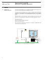
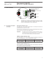
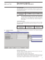
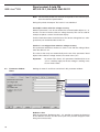
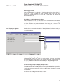
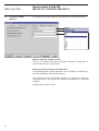
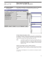
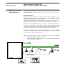
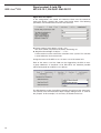
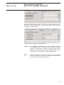
User Manual
ABB i-bus® EIB
Zone terminal FM
MT/U 2.12.1
Intelligent Installation Systems
®
ABB i-bus EIB
Zone terminal, 2-fold, FM
MT/U 2.12.1, GH Q631 0060 R0111
Contents
1
Page
General
1.1 Product and functional overview . . . . . . . . . . . . . . . . . . . . . . . . . .
2
1.2 System benefits . . . . . . . . . . . . . . . . . . . . . . . . . . . . . . . . . . . . . .
3
2
Device configuration
2.1 Technical data . . . . . . . . . . . . . . . . . . . . . . . . . . . . . . . . . . . . . . . .
4
2.2 Device connection . . . . . . . . . . . . . . . . . . . . . . . . . . . . . . . . . . . .
5
2.3 Description of the inputs and outputs . . . . . . . . . . . . . . . . . . . . . .
5
2.4 Functional overview . . . . . . . . . . . . . . . . . . . . . . . . . . . . . . . . . . .
6
3
Function and operation
4
Project design and programming
4.1 Communication objects . . . . . . . . . . . . . . . . . . . . . . . . . . . . . . . .
7
4.2 Parameter window: General . . . . . . . . . . . . . . . . . . . . . . . . . . . . .
9
4.3 Parameter window: Zones . . . . . . . . . . . . . . . . . . . . . . . . . . . . . .
10
4.4 Parameter window: Supply Voltage . . . . . . . . . . . . . . . . . . . . . . .
11
4.5 Parameter window: Walk Test . . . . . . . . . . . . . . . . . . . . . . . . . . . .
12
4.6 Parameter window: Setting/Arming . . . . . . . . . . . . . . . . . . . . . . .
13
4.7 Behaviour on bus voltage failure and recovery . . . . . . . . . . . . . . .
14
4.8 Behaviour on supply voltage failure and recovery . . . . . . . . . . . .
14
5
Planning and application
5.1 Overview and general recommendations . . . . . . . . . . . . . . . . . . .
15
5.2 Stand-alone operation without central security logic . . . . . . . . . .
15
5.3 Operation in connection with intruder alarm control unit L208 . . .
17
6
Appendix
6.1 Ordering information . . . . . . . . . . . . . . . . . . . . . . . . . . . . . . . . . . .
20
This manual describes the function of the EIB zone terminal MT/U 2.12.1.
Subject to change without prior notice. Irrtümer vorbehalten?
1
®
ABB i-bus EIB
1
General
1.1
Product and
functional overview
Zone terminal, 2-fold, FM
MT/U 2.12.1, GH Q631 0060 R0111
The zone terminal MT/U 2.12.1 is used for the monitored connection of sensors from security technology to the ABB i-bus® EIB.
The device has two monitored circuits (”zones“) available, which continuously
supervise an EOL resistor of 2.7 kΩ. The device thus offers security against
deliberate or unintentional disconnection/short-circuiting of the detector
zones.
Since the device is flush-mounted, it can be positioned in the vicinity of the
detectors. It is suitable for the connection of conventional detectors such as
●
●
●
magnetic contacts,
passive infrared movement detectors,
glass-breakage sensors.
The connection of potential free contacts is possible in applications with
increased security requirements.
ER/U 1.1
MT/U 2.12.1
AT/S ...
Diagram 1: Example of room monitoring with lighting and heating control
2
US/U 4.1
®
ABB i-bus EIB
1.2
System benefits
Zone terminal, 2-fold, FM
MT/U 2.12.1, GH Q631 0060 R0111
The connection of EIB to security technology offers the user considerable
advantages.
Clear operation
The clear operation and display possibilities of EIB help to maintain an overview. The building thus always informs the user in clear text about the current
status of the building and security functions. If necessary, the user can also
be alerted via telephone.
Economic efficiency
New possibilities create economic benefits: detectors have multiple functions.
A movement detector can thus switch the lighting when the alarm system is not
set or the heating in the room is automatically lowered when a window is
opened (see diagram).
When the alarm system is set, these same detectors protect the building
from intruders.
Functions for convenience
Central functions can also be triggered in the building when the system is
set.
When leaving the building, the lighting is switched off and the room temperature is reduced if the alarm system has been set.
When the system is unset, the building creates pleasant lighting conditions
for the occupants on their return.
The lighting can be switched and the room temperature can be controlled
with the setting/unsetting of the alarm system in the building.
3
ABB i-bus EIB
Zone terminal, 2-fold, FM
MT/U 2.12.1, GH Q631 0060 R0111
2
Device configuration
The device functions of the MT/U 2.12.1 are outlined in this section.
2.1
Technical data
®
Power supply:
Supply voltage:
Bus voltage:
Inputs:
2 zones:
A and B
Primary circuit, EOL resistor. 2,7 kΩ
Open-circuit voltage 12 V DC
Short-circuit current max. 6 mA
Permitted cable resistance: max. 200 Ω
Outputs:
2 control outputs:
”Set/unset“, ”Walk test“
Output impedance 1,5 kΩ
Operating and
display elements:
Red LED and push button:
For entering the physical address
Connections:
Conductor cross-section:
ABB i-bus® EIB:
0,2 – 1 mm2
Bus connecting terminal
Miscellaneous:
Type of protection:
CE-mark:
IP 20 according to DIN EN 60 529
According to EN 50090-2-2 EMC-guideline
and low voltage guideline
– 5°C to + 45°C
In flush-type box ø 55 mm
54 x 28 mm
0.05 kg
Operating temperature rang:
Installation:
Dimensions (Ø x H):
Weight:
4
12 V DC ± 2 V SELV
Residual ripple ≤ 1,0 Vss
Power consumption < 35 mA, typ. 25 mA
via the ABB i-bus® EIB
Power consumption < 10 mA
®
ABB i-bus EIB
2.2
Zone terminal, 2-fold, FM
MT/U 2.12.1, GH Q631 0060 R0111
Device connection
Supply voltage
12 V DC
–
8
+
7
s/u +12 V
6
Test +12 V
5
+
4
–
3
+
2
–
1
Us = 12 V DC
B
A
to movement detector
EOL-resistor
2,7 kΩ
MT/U 2.12.1
c
EOL-resistor
2,7 kΩ
Un = 12V DC
ABB i-bus EIB
Detector contacts
The MT/U 2.12.1 requires an external power supply of 12 V DC.
A backup supply for the EIB bus voltage in the event of mains
failure is recommended for security applications.
Note:
2.3
Description of the inputs
and outputs
Zone inputs: (terminals 1 to 4)
The device has 2 zone inputs (terminal pairs 1-2 and 3-4). The zones are
provided with EOL resistors of 2.7 kΩ.
The zone input is undisrupted if the resistance value deviates from the reference value of 2.7 kΩ by less than approx. 200 Ω.
Important:
To enable the zone terminal to function correctly, even unused zone inputs must be terminated with a 2.7 kΩ resistor.
This can be carried out directly at the input terminals.
‘Walk test’ output: (terminal 5 ‘Test’)
The ‘Test’ output is a 12 V DC transistor output. The ‘Walk test’ function of
passive infrared detectors can be activated with this output.
‘Test‘ outputs
Walk test OFF
Walk test ON
0 V (high-resistance)
12 V (1,5 kΩ)
‘Set/unset’ output: (terminal 6 ‘s/u’)
The ‘s/u’ output is a 12 V DC transistor output, which indicates whether the
zone terminal is activated or deactivated.
‘s/u’ output
Device unset
Device set
0 V (high-resistance)
12 V (1,5 kΩ)
5
®
ABB i-bus EIB
Zone terminal, 2-fold, FM
MT/U 2.12.1, GH Q631 0060 R0111
Supply voltage inputs: (terminals 7 and 8)
The required 12 V DC supply voltage is connected at this point (terminal 7:
+12 V DC, terminal 8: 0 V DC). Terminal 8 is also used as the common reference potential for the outputs ‘Test’ and ‘s/u’.
2.4
Functional overview
Setting
The zone terminal is set via the EIB (communication object ”Set/Unset
Request“).
When the zone terminal is set, it is triggered by a fault in one of the zones
and the alarm memory (see below) is activated.
It is not possible to set the device if an alarm is active, if there is a fault in a
zone or if the supply voltage has failed; if an attempt is made to set the device, the communication object ”Set/Unset Request“ responds with the value
”0“.
Alarm and alarm memory
The alarm memory is activated if the device switches to the alarm state. An
alarm is triggered if there is a fault in one of the zones or on receipt of the
value ”1“ at the communication object ”Alarm“.
The alarm memory ensures that the value of a zone is not reset to ”0“ after
an alarm. It is thus possible to trace which detectors were triggered during
the alarm. When the device is unset, the values of the zones remain unchanged until a reset is carried out.
Walk test
Some detectors (e.g. infrared movement detectors) have a walk test input so
that the detection range can be set. When the walk test is activated, an LED
on the movement detector indicates whether movement has been recorded.
The zone terminal therefore has a walk test function available with the associated output. When the walk test is activated, the voltage at the ‘Test’ output
is 12 V DC.
The ‘Test’ output can be set with a time limit. In this case, it switches off automatically once the set time has elapsed.
The walk test function is switched on and off via the bus (communication
object ”Walk Test“).
Reset
A reset must be carried out after an alarm to delete the alarm state. A reset
can only be carried out when the device is unset. This process deletes and
deactivates the alarm memory.
The reset request is received via the bus (communication object ”Reset“).
Switch off zones
It is possible to switch off any zones via the bus. If a zone is switched off,
it does not trigger any alarms or prevent the device from being set.
6
ABB i-bus EIB
Zone terminal, 2-fold, FM
MT/U 2.12.1, GH Q631 0060 R0111
3
Function and
operation
This section does not apply.
4
Project design and
programming
4.1
Communication objects
®
The application software has ten 1 bit communication objects.
Some of the communication objects are dynamic and only visible if the corresponding parameters have been activated in the application software.
Zone objects ”Status Zone A/B“ (1 bit)
Each zone has a separate 1 bit communication object which can send the
status of the zone to the EIB bus.
Status
of zone
Telegram value ”0“
Telegram value ”1“
No fault
Fault
If the alarm memory is activated, the telegram value does not revert to ”0“
until a reset has been carried out. A reset is only possible if the device is
deactivated.
”Set/Unset Request“
With the communication object ”Set/Unset Request“, the device receives a
request for setting or unsetting. If it is not possible to set the device, this
communication returns the value ”0“. This also prevents other devices from
being set.
7
®
ABB i-bus EIB
Zone terminal, 2-fold, FM
MT/U 2.12.1, GH Q631 0060 R0111
Telegram value ”0“
Telegram value ”1“
Receive
”Unset“
request
”Set“
request
Send
Response
”Setting
is not possible“
”Alarm“
If an alarm is triggered while the device is set (e.g. due to a fault in a zone),
the communication object ”Alarm“ is sent on the bus with the value ”1“.
An alarm can only be deleted by a reset when the device is unset
(see communication object ”Reset“).
If the device receives the value ”1“ at the communication object ”Alarm“,
(e.g. from another zone terminal), the alarm memory is switched on.
Status
of the device
Telegram value ”0“
Telegram value ”1“
No alarm
Alarm,
alarm memory ON
”Walk test“
The walk test function of the zone terminal can be switched on with the communication object ”Walk Test“ (value ”1“) or switched off (value ”0“).
Status
of the ‘Test’ output
Telegram value ”0“
Telegram value ”1“
Switched off (0 V)
Switched on (12 V)
If the zone terminal switches the walk test function off automatically during
timed operation, this information is not sent on the bus.
”Reset“
A reset of the zone terminal can be requested via the communication object
”Reset“.
A reset is only possible when the device is deactivated.
Receipt
of telegram
Telegram value ”0“
Telegram value ”1“
–
”Reset“ request
”Supply Voltage Fault“
The status of the 12 V DC supply voltage is reported with this communication object. By sending this telegram cyclically, the presence of the zone terminal can be monitored on the bus.
Status
of the supply voltage
8
Telegram value ”0“
Telegram value ”1“
OK
Fault
®
ABB i-bus EIB
Zone terminal, 2-fold, FM
MT/U 2.12.1, GH Q631 0060 R0111
”Set Confirmation“
The communication object ”Set Confirmation“ contains the current state of
the zone terminal. The status is sent on the bus once the device has been
successfully set or unset.
Status
of the device
Note:
Telegram value ”0“
Telegram value ”1“
Unset
Set
This communication object can generate a high telegram load
on the bus when many devices are set or unset. If the state of
an alarm system is to be displayed on several zone terminals
MT/U 2.12.1, the communication object ”Set/Unset Request“ is
more suitable.
”Switch Off Zone A/B“
Zones can be switched off individually. A disconnected zone does not trigger
any alarms and does not prevent the device from being set; its status is displayed on the bus.
Function
of the zone
4.2
Parameter window:
General
Telegram value ”0“
Telegram value ”1“
Switched on
Switched off
General settings for the device are carried out in the ”General“ parameter
window:
Activate alarm memory
The alarm memory is normally activated in the alarm state. This can be prevented by setting the parameter value to ”no“.
Inactive waiting time after bus voltage recovery
The initialisation time determines the period when no telegrams are sent by
the device after bus voltage recovery. If various devices have different initialisation periods, a telegram overload on the bus can be prevented.
9
®
ABB i-bus EIB
Zone terminal, 2-fold, FM
MT/U 2.12.1, GH Q631 0060 R0111
Note: The minimum period of 5 seconds corresponds to the minimum period in the technical specifications.
During this period, the outputs ‘Test’ and ‘s/u’ are undefined.
Send object values after bus voltage recovery
With this parameter, it can be set whether the communication objects 0, 1, 3,
6 and 7 are sent on the bus after bus voltage recovery. This can be used for
example to update a central visualisation display.
Further information about the behaviour of the device during/after bus voltage recovery can be found under section 4.7.
If device is set: trigger alarm after bus voltage recovery
This parameter determines whether an alarm is sent after bus voltage failure
when the device is set.
The value is then only sent automatically on the bus if the parameter ”Send
object values after bus voltage recovery“ has been set to ”yes“.
Important:
4.3
Parameter window:
Zones
To prevent false alarms, this parameter should only be set to
”yes“ if a backup supply for the bus voltage is existing in the
case of mains failure.
Settings for zones A and B are carried out in this parameter window:
Debounce time
With the parameter ”Debounce time“, it is possible to support the bouncing
of the detector contacts and the zone inputs. This prevents telegrams from
being sent unnecessarily.
10
®
ABB i-bus EIB
Zone terminal, 2-fold, FM
MT/U 2.12.1, GH Q631 0060 R0111
Zone triggers alarm
If the parameter value is selected as ”no“, the value of the object ”Alarm“ is
not set to ”1“ after a fault in this zone when the device is set. The alarm
memory is also disabled for this zone and a signal does not prevent the
device from being set.
Possibility to switch off zone via object
If this parameter is set to ”yes“, the zone can be switched off via the communication object ”Switch Off Zone A/B“. A disconnected zone does not trigger
an alarm and does not prevent the device from being set; its status is still
displayed on the bus.
4.4
Parameter window:
Supply Voltage
Settings for the communication object ”Supply Voltage Fault“ are carried out
in this parameter window. This can for example be used to monitor the presence of the device.
Fault of supply voltage triggers alarm
In the event of a fault in the 12 V DC supply voltage, it can be set whether
the communication object ”Alarm“ also contains the value ”1“ (parameter value ”yes“) in addition to the communication object ”Supply Voltage Fault“.
Cyclic sending of object ”Supply Voltage Fault“
The function ”Cyclic sending of object ”Supply Voltage Fault“ can be activated or deactivated. The sending interval can be specified with the parameters
”Cyclic sending: time base“ and ”Cyclic sending: factor“. The time is calculated as follows:
Duration of the sending interval = Base x Factor.
11
ABB i-bus EIB
Zone terminal, 2-fold, FM
MT/U 2.12.1, GH Q631 0060 R0111
4.5
The settings for the ‘Test’ output are carried out in this parameter window.
®
Parameter window:
Walk Test
Walk test after bus voltage recovery
It can be set whether the walk test function should be ”switched on“ or
”switched off“ after bus voltage failure.
Normal operation and time-limited operation
In the operating mode ”normal operation“, the ‘Test’ output is switched on or
off via the ”Walk Test“ communication object.
If the operating mode ”time-limited operation“ is selected, the output is
switched off after a set interval. This maximum operating time is calculated
as follows:
Operating time = Base x Factor
12
®
ABB i-bus EIB
4.6
Parameter window:
Setting/Arming
Zone terminal, 2-fold, FM
MT/U 2.12.1, GH Q631 0060 R0111
The settings for behaviour on setting/unsetting the device as well as the
settings for the ”s/u“ output are carried out in this parameter window.
Prevent setting if zone detects a fault
If a zone or the supply voltage has a fault or the ”Alarm“ communication objects displays an alarm, it is normally not possible to set the device. Using
this parameter, it is however possible to specify that the device can be set in
spite of an active signal, fault or alarm (parameter value ”no“).
Note:
You should only modify this parameter in conjunction with an intruder alarm control unit or a central alarm logic which controls
the arming of the device. If an attempt is made to set the zone
terminal when an active zone is triggered, an alarm will immediately be issued.
Negative acknowledge via object ”Set/Unset Request“
If it not possible to set the zone terminal, one device will normally respond to
the request with the value ”0“ and thus reset other devices to the ”unset“
mode.
This negative acknowledgement can be prevented by selecting the parameter value ”no“.
13
®
ABB i-bus EIB
Zone terminal, 2-fold, FM
MT/U 2.12.1, GH Q631 0060 R0111
Time delay of confirmation
Using this parameter, it is possible to set a delay between the setting of the
device and the confirmation that the device is set via the communication
object ”Set Confirmation“ and the output ‘s/u’.
Normal operation and time-limited operation
During normal operation, the voltage at the ‘s/u’ output in set mode is 12 V;
when the device is deactivated the voltage at the output is 0 V (highresistance).
If the operating mode ”time-limited operation“ is selected, the output is switched off after a set interval. This maximum operating time is calculated as
follows:
Operating time = Base x Factor.
4.7
Behaviour on bus voltage
failure and recovery
During a bus voltage failure, all the outputs and zone inputs are switched off
(0 V).
After bus voltage recovery, the device waits for an adjustable initialisation
period. During this interval, no telegrams are sent on the bus and the status
of the outputs remains unchanged. Any received telegrams are detected
approx. 5 seconds after bus voltage recovery.
Provided that the relevant settings have been made in the parameters, the
device sends the following communication objects on the bus on bus voltage
recovery:
– Object 0: Status Zone A
– Object 1: Status Zone B
– Object 3: Alarm
– Object 6: Supply Voltage Fault
– Object 7: Set Confirmation
The set/unset state of the device remains unchanged after bus voltage
recovery.
4.8
Behaviour on supply voltage If the 12 V supply voltage of the device fails, the device sends the value ”1“
failure and recovery
to the communication object ”Supply Voltage Fault“.
The zones cannot be evaluated without supply voltage and the display of the
zones on the bus is thus undefined.
If the device is armed, the communication object ”Alarm“ is set to ”1“ and
sent provided that the relevant parameter settings have been selected.
No alarms are sent when the device is unset.
The fault signal of a zone can only be deleted by a reset when the device is
unset. The deletion is possible if the fault has been rectified.
14
®
ABB i-bus EIB
5
Planning and
application
5.1
Overview and
general recommendations
5.2
Stand-alone operation
without central security
logic
Zone terminal, 2-fold, FM
MT/U 2.12.1, GH Q631 0060 R0111
●
For applications with standard security requirements, the MT/U 2.12.1
normally operates on the EIB without any central security logic (”standalone operation“).
●
In installations with increased requirements for functionality and security,
it is advisable to operate the MT/U 2.12.1 in connection with an intruder
alarm control unit L 208 with an EIB interface.
●
A backup supply for the bus voltage in the case of mains failure is recommended.
●
The communication object ”Set Confirmation“ is not generally required in
the configurations described. If you however use this object – for example
to display the arming of each individual MT/U 2.12.1 – please note that
a high telegram load can arise while setting and deactivating the device.
Planning overview
It is possible to operate several zone terminals MT/U 2.12.1 without an
intruder alarm control unit. In this configuration, the device makes basic
security functions available such as controlling the setting/unsetting of the
device, triggering alarms and resetting the system.
Please note the following points:
●
It is advisable to provide a backup supply for the EIB bus voltage and the
12 V DC supply voltage in the case of mains failure.
●
If the alarm system should distinguish between internal and external
set, outdoor and indoor detectors should be connected to different zone
terminals.
15
®
ABB i-bus EIB
Zone terminal, 2-fold, FM
MT/U 2.12.1, GH Q631 0060 R0111
US/U 4.1
8
Us = 12 V DC
8
Us = 12 V DC
8
Us = 12 V DC
AT/S x.x.x
TS/AP
8
Us = 12 V DC
8
Us = 12 V DC
8
Us = 12 V DC
+
7
+
7
+
7
+
7
+
7
+
7
s/u +12 V
6
s/u +12 V
6
s/u +12 V
6
s/u +12 V
6
s/u +12 V
6
s/u +12 V
6
Test +12 V
5
Test +12 V
5
Test +12 V
5
Test +12 V
5
Test +12 V
5
Test +12 V
5
+
4
+
4
+
4
+
4
+
4
+
4
B
B
3
+
A
2
B
3
+
A
1
2
B
3
+
A
1
2
B
3
+
A
1
2
B
3
+
A
1
2
3
+
A
1
2
1
aBB
MT/U 2.12.1
aBB
MT/U 2.12.1
aBB
MT/U 2.12.1
aBB
MT/U 2.12.1
aBB
MT/U 2.12.1
aBB
MT/U 2.12.1
ABB i-bus EIB
Un = 12V DC
ABB i-bus EIB
Un = 12V DC
ABB i-bus EIB
Un = 12V DC
ABB i-bus EIB
Un = 12V DC
ABB i-bus EIB
Un = 12V DC
ABB i-bus EIB
Un = 12V DC
n x MT/U 2.12.1
Application description
The following section describes the procedure for creating a linked alarm
system from several MT/U 2.12.1 devices.
Link the communication objects
●
●
●
”Set/Unset Request“
”Alarm“
”Reset“
with the same group address each. You can thus ensure that basic security
functions for setting the device, issuing alarms and resetting the system are
carried out together.
The parameters of the MT/U 2.12.1 can remain in the default setting.
A minimum requirement for operating the alarm system - apart from the
arming device – is a push button with a ”reset“ function. An option for setting
the device internally can also be provided for example.
If the user stays inside the building, a so-called ”internal set“ only activates
the detectors for outdoor surveillance. Since the zone terminal does not
distinguish between the different ways of setting the device, only the devices
which are connected to the outdoor detectors are setted in this case.
When the system is set externally, it is important to disable the internal arming device or to prevent unintentional operation.
The alarm can be issued for example via an EIB switch actuator with a siren
and/or flashing light. These external devices that are outside the security
area can also be monitored for tampering via an individual zone.
Important: An external siren should only issue timed alarms
(typically: 120 seconds).
16
®
ABB i-bus EIB
5.3
Operation in connection
with the intruder alarm
control unit L208
Zone terminal, 2-fold, FM
MT/U 2.12.1, GH Q631 0060 R0111
The interaction between the MT/U and the intruder alarm control unit L208
with EIB interface L208/EIB (application program ”Alarm Panel Interface/1“)
is described here.
Planning overview
The intruder alarm control unit L208 with EIB interface L208/EIB can be
extended by EIB detectors. It is also possible to link professional security
functions with the ease of operation of EIB.
Since the L208 takes over the central control of the security functions in this
configuration, the highest level of functionality and reliability is achieved.
Detectors can be connected to zones 1 to 8 of the control unit both conventionally and via the EIB. It is possible to carry up to four EIB signals logically
to one zone of the control unit, so that a maximum of 32 EIB zones can be
managed. The EIB zones can still be displayed individually on the EIB.
Up to 8 zone terminals can be monitored cyclically for activity. If no cyclical
monitoring is required and/or a further monitoring logic is used, it is possible
to increase the number of zone terminals.
Note: The L208 requires at least one battery SAK 7 and an operator
keypad L208/PT or L840/PT to function.
The L208 makes a backup supply of 12 V DC available for the zone
terminal via the EIB interface.
17
®
ABB i-bus EIB
Zone terminal, 2-fold, FM
MT/U 2.12.1, GH Q631 0060 R0111
Application description
In this configuration, the control unit L208 has taken over the control for
arming the device, resetting the system and issuing alarms. The following
parameters can therefore be set on the zone terminal:
●
●
Prevent setting if zone detects a fault = ”no“:
The alarm control unit prevents the device from being set.
„Negative acknowledge via object ”...“ = ”no“:
A zone terminal cannot cancel the activation of the system. This function
is reserved for the alarm control unit.
Assign the zones of the MT/U 2.12.1 to zones 1–8 of the control unit.
Each of the zones 1-8 of the L208 can be triggered by the EIB via max.
4 group addresses. A maximum of 32 EIB zones are therefore possible
which corresponds to 16 MT/U 2.12.1 devices.
The EIB interface makes it possible to monitor the activity of the zone terminal cyclically. The communication object ”Supply Voltage Fault“ is used for
this purpose. In this example, it is sent every 9 seconds on the bus:
18
®
ABB i-bus EIB
Zone terminal, 2-fold, FM
MT/U 2.12.1, GH Q631 0060 R0111
The object ”Supply Voltage Fault“ is linked via a group address with an
”EIB-Tamper“ communication object of the L208/EIB. This is parameterised
as follows on the EIB interface:
Within 30 seconds of the monitoring time, the communication object ”Supply
Voltage Fault“ of the zone terminal would have to be sent at least 3 times
on the bus (9 x 3 = 27). If it is missing during this period or sends the value “1“,
a tamper alarm is triggered on the control unit.
Caution:
The L208/EIB has 8 ”EIB-Tamper“ communication objects and
can therefore monitor the activity of max. 8 devices cyclically.
Further zone terminals can display a supply voltage fault by
linking the communication object ”Supply Voltage Fault“ with an
”EIB Tamper“ object without the cyclical sending function.
Note:
Cyclical monitoring of activity can lead to a high telegram
load on the bus. Please take this into consideration when setting
the cyclic interval and monitoring period.
19
Zone terminal, 2-fold, FM
MT/U 2.12.1, GH Q631 0060 R0111
®
ABB i-bus EIB
6
Appendix
6.1
Ordering information
Description
Zone terminal FM
20
Ordering info.
Short description
Order no.
bbn
40 16779
EAN
MT/U 2.12.1
GH Q631 0060R0111
51380 7
Unit
weight
in kg
Pack
units
0.05
1
Publication No. G SK 09098 01 S0201
ABB STOTZ-KONTAKT GmbH
Postfach 10 16 80
D-69006 Heidelberg
Telefon (0 62 21) 7 01-434
Telefax (0 62 21) 7 01-724
www.abb-stotz-kontakt.de


![取扱説明書 [PDF形式]](http://vs1.manualzilla.com/store/data/006702826_2-8afa28eabb59708af9b20ba1724b287b-150x150.png)