1
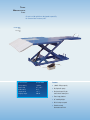
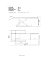
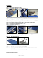
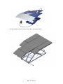
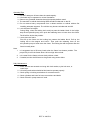
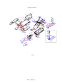
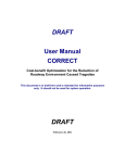
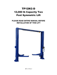
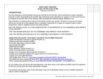
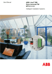
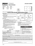
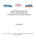
M-1300C-TRIKE
1300 lb Capacity Trike Lift
USER’S MANUAL
REV A-1025513
TRIKE
MOTORCYCLE
LIFT
An extra wide platform designed especially
for three-wheel motorcycles.
M-1300 -TRIKE
Trike
Motorcycle
Lift
SPECIFICATIONS:
M-1300 -TRIKE
Features:
Lifting capacity
Height range
Width overall
Length overall
Shipping weight
1,300 lbs.
6 3⁄4”- 38 1⁄2”
62 1⁄4”
132 1⁄4”
660 lbs.
✦
1,300 lb. lifting capacity
✦
Air/hydraulic pump
✦
Designed especially for
three-wheel motorcycles
✦
Extra-large platform
✦
38” working height
✦
Built in drop-out panel
✦
Powder-coated,
diamond tread finish
TUXEDO DISTRIBUTORS LIMITED WARRANTY
Structural Warranty:
The following parts and structural components carry a five year warranty:
Columns
Legs
Top Rail Beam
Carriages
Uprights
Arms Swivel Pins
Tracks Overhead Beam Cross Rails
Limited One-Year Warranty:
Tuxedo Distributors, LLC (“Tuxedo”) offers a limited one-year warranty to the original purchaser of
Tuxedo lifts and Wheel Service in the United States and Canada. Tuxedo will replace, without charge, any
part found defective in materials or workmanship under normal use, for a period of one year after purchase.
The purchaser is responsible for all shipping charges. This warranty does not apply to equipment that has
been improperly installed or altered or that has not been operated or maintained according to specifications.
Other Limitations:
This warranty does not cover:
1.
2.
3.
4.
Parts needed for normal maintenance
Wear parts, including but not limited to cables, slider blocks, chains, rubber pads and pulleys
Replacement of lift and tire changer cylinders after the first 30 days. A seal kit and installation
instructions will be sent for repairs thereafter.
On-site labor
Upon receipt, the customer must visually inspect the equipment for any potential freight damage before
signing clear on the shipping receipt. Freight damage is not considered a warranty issue and therefore must
be noted for any potential recovery with the shipping company.
The customer is required to notify Tuxedo of any missing parts within 72 hours. Timely notification must
be received to be covered under warranty.
Tuxedo will replace any defective part under warranty at no charge as soon as such parts become available
from the manufacturer. No guarantee is given as to the immediate availability of replacement parts.
Tuxedo reserves the right to make improvements and/or design changes to its lifts without any obligation
to previously sold, assembled or fabricated equipment.
There is no other express warranty on the Tuxedo lifts and this warranty is exclusive of and in lieu of all
other warranties, expressed or implied, including all warranties of merchantability and fitness for a
particular purpose.
To the fullest extent allowed by law, Tuxedo shall not be liable for loss of use, cost of cover, lost profits,
inconvenience, lost time, commercial loss or other incidental or consequential damages.
This Limited Warranty is granted to the original purchaser only and is not transferable or
assignable.
Some states do not allow exclusion or limitation of consequential damages or how long an
implied warranty lasts, so the above limitations and exclusions may not apply. This warranty
gives you specific legal rights and you may have other rights, which may vary from state to state.
1905 N Main St Suite C, Cleburne, TX 76033
Ph 817-558-9337
Fax 817-558-9740
Lift Specifications:
Lift Frame:
Overall Width:
Overall Length:
Raised Height (max):
Lifting Capacity:
Air-hydraulic pump:
62-1/4”
132-1/4”
53”
1320lbs
(compressed air) 8 bar / 116 psi
5
REV A-1025513
Installation
STEP 1 Open the box, take out the lift frame.
STEP 2 Lift up the deck until it rest on the lock position.(Fig. 2)
STEP 3
STEP 4
STEP 5
STEP 6
STEP 7
STEP 8
Fig. 2
Fig. 3
Fig. 4
Connect the hose and the hydraulic foot pump.( Fig. 3) Remember to change the oil
tank plug with the ventilating one supplied.
Connect the compressed air to the foot pump. ( Max. pressure 8bar/ 112 psi) (Fig.4)
Lift up the deck with the foot pump.
Mount the long and short connecting rods on the main deck for side boards.
Put on the side boards and lock them (Fig. 5-6) .
Put on the rear ramps (Fig. 7)
Fig.5
Fig.6
STEP 9 Mount the front extension board if purchased.(Fig. 8)
STEP 10
Inset the front stop bar.
STEP 11
STEP 12
Fig. 7
Fig.8
Fig.9
Mount the front wheel vise if purchased.(Fig. 9)
Raise the deck to the highest position then lower it down to bottom for two or
three circles.
Note: the lock shall be released before lowering.
Now the lift is ready for operation.
6
REV A-1025513
The side boards can be mounted on front also. See picture below.
7
REV A-1025513
Operating Tips:
1. DO NOT attempt to lift more than the rated capacity.
2. Lift should only be operated on a level foundation.
3. Remove any potential obstacles that might impede platform travel.
4. The machine or vehicle that is being lifted should be balanced on the lift.
5. Do not remove heavy components from a raised machine or vehicle without first
installing adequate supports .The vehicle may become unbalanced and fall.
6. Lock the frame at heights.
During lifting, when the locking bar’s end just pass the ladder block of the height,
stop the air-hydraulic pump, then push the releasing lever to lower down the frame.
The lift will be lock at the position.
7. Lower down the frame.
First lift up the frame so the locking bar passes the ladder block. Pull up the
locking bar to the magnet and hold it. Then push the releasing lever on the
air-hydraulic pump to lower down the frame. The locking bar will drop down after the
frame is totally down.
Note:
1. It is suggested not to lift heavy loads when the frame is at bottom position. The
proper way is to lift the frame about 100 mm high without load.
2. It is normal for the frame to lower slowly without a load.
3. If needed, anchor the lift frame to the ground using anchor bolts.
Daily Maintenance:
1. Insure all bolts are secured and snug with lock washer, nylon lock nuts, or
cotter keys.
2. Lift locking mechanism should be lubricated to operate properly.
3. Check spring on locking mechanism for constant tension.
4. Check cylinders and hose for loose connections and leaks
5. Check oil level in pump reservoir / tank.
8
REV A-1025513
Troubleshooting:
1. Air-hydraulic pump will not operate.
- Check compressed air supply.
2.
Lift mechanism does not move up and down smoothly.
- Move vehicle location on the lift for more equal weight distribution.
- Raise the lift all the way to the top and then return to floor. Repeat 4-6 times
in order to get the air out of the hydraulic system.
3.
Lift does not lift its rated capacity.
- Move vehicle location on the lift for equal weight distribution.
- Check the pressure of the compressed air supply.
Make sure the pump is getting adequate air.
4.
Cylinder leak under rated load
- Check for leaks at the hydraulic hose, fittings, cylinders and pumps.
- Contamination may be in the check valve preventing the valve from completely
closing.
If cylinder continues to leak down, pump may have a faulty valve. Contact the
service engineer.
5.
Lift will not lower
- Raise the lift up one to two inches. Let the sliding block bar fully pass the locking
ladder then pull the bar to magnet. If the magnet does not work, change it
with a new one.
- Check the lift frame for any obstacles preventing lowering.
9
REV A-1025513
PARTS DRAWING
9
8
20
23
5
2-1
7
6
12-1
2-1
27
21
4
28
20
10
3
13
24
26 25
22
20
23
20
11 3
2
32
20
2-2
12
33
17
1
31
20
19-17
19-16
19-15
19-14
19-13
25
19-12
29
19-11
30
19-6
19-10
19-5
19-9
19-8
19-4
19-7
19-3
19-2
19-1
20
10
5
13
19 18
18
15-1
7
15-2
11
8
14-9
15-3
14
38
3420
14-8
37
14-7
14-6
14-4
14-5
14-3
14-2
35
15-4
15-5
15-6
15-7
14-13
14-12
14-10
14-11
15-13
15-12
15-11
15-10
15-9
15-8
4:1
14-1
17
36
15
14-1
16
Fig. A
10
REV A-1025513
PARTS LIST
ITEM
CODE
DESCRIPTION
QTY
1
JP17-08000-000
rear plate
1
2
JP19-00003-000
short connecting rod
2
2-1
JP19-00004-000
fixing rod
2
2-2
JP19-00005-000
long connecting rod
1
3
5202-00008-000
nut
8
4
JP17-00001-000
main ramp
1
5
JP19-00001-000
side board
2
6
JP04-00004-000
pin
4
7
5301-00008-000
flat washer
8
8
5101-08020-000
bolt
8
9
JP17-00011-000
front stop bar
1
10
5105-10030-000
socket head bolt
8
11
5303-00008-000
spring washer
4
12
JP18-01000-000
main deck
1
12-1
JP19-00006-000
front extension
1
13
JP19-00002-000
side ramp
2
14
QY030S-00
air-hydraulic pump
1
14-1
5308-00014-000
copper wash
2
14-2
JP17-07204-000
output connector
1
14-3
5901-00010-000
O-ring
1
14-4
JP17-07202-000
connector
1
14-5
JP17-07203-000
locking nut
1
14-6
5308-00012-000
copper wash
1
14-7
JP17-14001-000
output connector
1
14-8
JP01-08003-000
protection
1
14-9
JP01-08005-000
fixing board
1
14-10
JP01-08004-000
holding board
1
14-11
5110-06010-000
screw
6
14-12
5306-00006-000
spring washer
6
14-13
5301-00006-000
flat washer
6
15
JP17-13000-000
single way valve
1
15-1
JP17-13002-000
knob
1
15-2
5112-04006-000
threaded pin
1
15-3
JP17-13001-000
valve pin
1
15-4
JP17-13004-000
Back ring
1
15-5
5901-25718-000
O-ring
1
15-6
5112-05005-000
threaded pin
1
11
REV A-1025513
ITEM
CODE
DESCRIPTION
QTY
15-7
JP17-13005-000
washer
1
15-8
JP17-13009-000
valve body
1
15-9
5601-00005-000
ball
1
15-10
JP17-13006-000
ball seat
1
15-11
JP17-13007-000
spring
1
15-12
JP17-13008-000
screw
1
15-13
JP17-13003-000
threaded sleeve
1
16
JP17-00012-000
extension connector
1
17
JP08-04004-000
hose
1
18
JP17-00004-000
cylinder shaft
2
19
JP17-04000-000
cylinder
1
19-1
JP17-04200-000
piston rod
1
19-2
5901-00190-000
O-ring
1
19-3
5309-00052-000
Circlip
1
19-4
5906-00300-000
dust ring
1
19-5
JP08-04005-000
Guide ring
1
19-6
JP17-04002-000
position ring
1
19-7
JP08-04003-000
piston
1
19-8
JP08-04002-000
guide ring
1
19-9
5901-00400-000
O-ring
1
19-10
5905-00400-000
U-ring
1
19-11
5304-00025-000
Circlip
1
19-12
JP17-04100-000
cylinder body
1
19-13
JP17-04004-000
board
3
19-14
QY02-02101-000
spring
3
19-15
SJ05-03015-000
limit valve
3
19-16
5308-00140-000
copper washer
1
19-17
JP08-04001-000
connector
1
20
5304-00020-000
circlip
18
21
JP17-00002-000
shaft 1#
2
22
JP17-02000-000
scissor frame 1#
1
23
JP17-00012-000
roller
4
24
5110-05035-000
screw
2
25
5301-00005-000
flat washer
4
26
JP17-06000-000
safety bar
1
27
JP08-00009-000
magnet
2
28
5110-03008-000
screw
4
12
REV A-1025513
29
CODE
5306-00005-000
DESCRIPTION
spring washer
QTY
2
30
5201-00005-000
nut
2
31
JP17-00007-000
shaft 4#
1
32
JP17-05000-000
scissor frame 2#
1
33
JP17-03000-000
bottom frame
1
34
JP17-00003-000
shaft 2#
2
35
JP17-00010-000
screw cap
1
36
JP17-00009-000
balance bar
1
37
5206-00006-000
self locking bar
2
38
5101-06050-000
bolt
2
ITEM
13
REV A-1025513