1
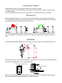
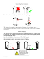
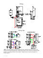
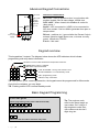
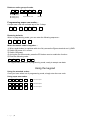
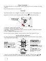
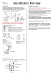
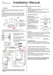
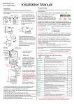
Installation & User Manual
For
605 DECT+2.4G Intercom
W ireless Video Inter com System
Models 605AB, 605ABK
P a g e |1
Contents
Overview of system
Site Survey
Mounting the Transmitter
Power supply
Mounting Architectural Panels
Mounting Hooded Panels
Mounting Flush Panels
Wiring
Code Lock Keypad Connections
Wiring Tips
Keypad Overview
Basic Keypad Programming
Full Keypad programming
Using the Keypad
The Handset
Recoding / Adding a Handset
Testing
Using the Intercom Handset
Maintenance of the Intercom
Troubleshooting
P a g e |2
…………….Pg 3
…………….Pg 3
…………….Pg 3
…………….Pg 3
…………….Pg 4
…………….Pg 4
…………….Pg 4
…………….Pg 5
…………….Pg 5
…………….Pg 6
…………….Pg 6
…………….Pg 7
…………….Pg 7
…………….Pg 9
…………….Pg 9
…………….Pg 9
.………….Pg 10
.………….Pg 10
.………….Pg 10
.………….Pg 11
Overview of System
Please read this entire manual before attempting to install this system.
This system should only be installed by a professional automatic gate installer or access control
specialist installer.
It is recommended that the system be range tested on site BEFORE being fully installed.
Site Survey
Before installing this system, you need to be sure that the range of the system will be sufficient.
The transmitter and speech unit can be powered up, call button pressed, and then check that the
handset will ring from all areas in which it will be used.
Tip: For longer range installations, locate the handset close to the front of the property, near a
window if possible. Concrete walls can reduce the open air range of 350 metres by 30-50% per
wall.
Installation
Assuming satisfactory operation at full range, you are ready to fully install the product.
Mount the intercom at the desired height for pedestrian or car users. The camera angle
is wide at 90 degrees to cover most scenarios.
Loosen top 2 screws only
Hinge front door
Side View
Tip: Do not drill holes in the wall with the intercom in positon, otherwise dust may get
around the camera window and impair the camera view.
P a g e |3
Mounting the Antenna
Mount the antenna as high as possible to achieve longest range.
TIP: Antenna beam width is approximately 40 degrees. For short range door
intercoms, ask your distributor or dealer for an omni-pole type antenna with 360 degree
beam angle.
Power Supply
TIP: Most technical calls received are due to installers using CAT5 or alarm cable
to power the unit. Neither are rated to carry enough power (1.5 amp peak). Please
use following cable sizes…
Up to 2 metres (6 feet) – Use minimum 0.75mm2 (18 gauge)
Up to 4 metres (12 feet) – Use minimum 1mm2 (16 gauge)
Up to 8 metres (24 feet) – Use minimum 1.5mm2 (14 gauge)
Call point
Call point
Power supply
Excessively long
cable!!
P a g e |4
Mains power
Power supply
Wiring
Wiring Tips
Note: The manufacturer can only support the use, operation and functionality of the
intercom and keypad themselves. Professional wiring to door release or automatic gate
systems is the responsibility of the installer. Please consult a security integrator for
further support.
P a g e |5
Advanced Keypad Connections
Tamper
N/C
OUT3
Advanced connections
INT Lock – Used to operate a door in conjunction with
another keypad. 24v dc max voltage, 100mA sink.
O/P1 inhib – When closed, this disables all codes for
relay group 1.
Sense – N/C connected to (-)GND, to be connected to
N/C door contact. Can be used to generate door open or
tamper alarm.
DU out – switches to (-) ground after the Duress Code is
entered. Used to trigger alarm zone, or buzzer to notify
guard. 100mA sink, 24VDC.
K or A – Not used.
INT Lock
O/P1 inhib
Sense
(-)GND
DU out
K or A
N/O
COM
N/C
+ egress
N/O
COM
N/C
N/O
COM
N/C
12v d.c
From power
supply
OUT1 OUT2
Keypad overview
This keypad has 3 outputs. The diagram below shows the LED indicators which indicate
programming and relay status information.
ON when incorrect codes entered and outputs are locked out.
GREEN when output 1 activated.
RED when output 2 activated.
1
2
3
FAST FLASHING – Wrong code entered / error.
4
5
6
SLOW FLASHING - in normal standby mode.
7
8
9
ON in programming mode.
*
0
#
ON when relay 3 activated.
TIP: After power up, as a security precaution, the keypad cannot be programmed for 60 seconds.
Once this time elapses, you may begin.
TIP: Flashing amber LED is normal standby mode!
Basic Keypad Programming
Quick start guide
1) Enter programming mode (amber LED should be ON)
0
0
0
0
*
*
2) Enter a new user code...
1
0
2
0
0
0
?
?
?
?
3) Exit programming mode
*
*
4) Enter the new user code to check the relay clicks.
P a g e |6
#
Tip: The engineer code
must be the same length as
user codes. So if using a 6
digit engineers code, then
user codes must also be 6
digits long etc.
Full Keypad programming
Enter programming mode..
0
0
0
0
*
The unit is now in programming mode. Amber LED on the
keypad should remain permanently on. 0000 is the default
programming passcode.
*
Exit programming mode..
*
The unit should exit programming mode and the amber LED
should start flashing again.
*
Enter a new ENGINEERS code…
Go into programming mode firstly then enter the following sequence…
0
1
?
Location
?
?
?
#
4-8 digit code
Replace ???? with your new ENGINEERS
code.
Validate
Enter or delete new user codes
There are 3 groups of user codes. Group 10 for relay 1, group 20 for relay 2, and group 30 for
relay 3. The programming sequence is shown below…
1
0
2
10= relay 1 codes
(1000 available)
20= relay 2 codes
(100 available)
30= relay 3 codes
(100 available)
0
0
0
?
?
Memory locations
000-999 for relay 1
001-100 for relay 2
001-100 for relay 3
2= add code
5= delete code
?
?
#
Pin code 4-8 digits
Validate
Example: Add user 31 to have access code 5555 operating relay 2….
2
0
2
Group 2
0
Add code
3
1
5
Location 31
5
5
5
Pin code 5555
#
Validate
Programming relay output times and modes…
?
?
0
or
1
-
9
9
9
9
0 = start / stop toggle mode (latching)
1-99999 = seconds momentary operation
51=relay1
52=relay2
53=relay3
Delete a user code even if you don’t know the code…
?
?
10=relay1
20=relay2
30=relay3
P a g e |7
5
Delete code
?
?
?
#
ID location to be deleted
Validate
9
#
Validate
Delete an entire group of codes
?
?
0
9
10=relay1 group
20=relay2 group
30=relay3 group
9
9
Super delete code
#
Validate
Programming super user codes…
A super user code can activate any of the 3 relays
0
2
?
Location
?
?
?
4-8 digit code
#
Validate
Restoring defaults
When in programming mode, you can enter the following sequence…
9
9
9
9
#
When the master code is forgotten….
1) Wire a push button (or replicate with wire link) across the Egress terminal and (-)GND.
2) Switch off power for 1 minute.
3) Switch ON power.
4) during the first 60 seconds, press the EG button once to enable the function.
5) Enter the following code..
8
0
8
0
*
*
The keypad should now be in programming mode, ready to accept new data.
Using the keypad
Using the standard codes…
Once you have exited out of programming mode, simply enter the user code.
Using super user codes
?
?
?
?
#
1
Activate output 1
?
?
?
?
#
2
Activate output 2
?
?
?
?
#
3
Activate output 3
P a g e |8
The Video Handset
The handset should be charged for 8 hours before use. It is recommended to give it at least 1
hour charge before range testing.
Answering Calls
1. When the intercom calls, identify the visitor on the screen.
40-80c
m
2. Press the OK button to answer the call.
3. Speak clearly into the top of the handset at a distance of 10-20cm.
10cm
4. During the call press < or > to increase or decrease volume.
5. Press
to activate door or gate release and press OK to end the call.
Note: The video will remain active for 1 minute after the audio call is ended.
P a g e |9
New Voicemail
The handset will store up to 16 voicemails if missed callers decide to leave a message at the door
/ gate unit.
Press OK button to listen to a new voicemails.
Settings
The following settings can be changed in the system. To make any of the following settings, put
the system into monitoring mode by pressing and holding the
key for a few seconds.
1. Brightness – Adjusts screen brightness.
2. Language – Select English, French or German.
3. Messages – Listen to or delete saved or older voicemails. (press KEY to delete any message).
4. Bell – Change ring tone.
5. Colour – Increase or decrease screen colour.
Use up and down arrows to navigate, and OK to select an option. Press right arrow to exit.
Optional Audio Handset
The audio handset should be charged for 8 hours before use. It is recommended to give it at least
1 hour charge before range testing.
Voicemail
When a call is not answered
within 40 seconds, the visitor
can leave a message. Once
complete, the handset will
display the
symbol. The unit
can store up to 16 messages.
Reception
indicator
Battery
Level
12.21
Voicemail
Symbol
Vibration
ON/OFF
ON/OFF
MENU
Charging
base
Power
LED
Code
Button
Change Ring Volume
Press and
to increase
and decrease ring volume
and press MENU to save.
Change Ring Tone
Press
and the handset will
ring with its currently selected
tone.
Press and
to cycle
through available ring tones
and press MENU to select
and save.
To listen to voicemail, press MENU to play. If there are more than 1 message, press
and
to select the message required and press MENU to play.
= Delete. Long press = delete all.
P a g e | 10
Using the Audio Handset
12.21
Answer /
end call
Change
ring tone
Open
door / gate
MENU
Select or enter
Up and down arrows
increase / decrease ring
and speech volume
Re-coding the Handsets / Adding an Extra Handset
Occasionally a system may need re-coded when it arrives on site. If the handset does not ring
when the call button is pressed, please perform the following steps..
1. Press and hold the code button on the speech panel as shown for 3 seconds.
2. Press and hold the code button on the handset (use a fine object like ball point pen) for up to 10
seconds.
3. While holding, the handset should bleep once, then bleep again, then emit a melody
confirmation tone.
Once the melody is heard, the handset should then be working. The system should now be ready
for testing.
P a g e | 11
Testing
1. Press the call button on the intercom and all coded handsets should ring (max 4 handsets).
2. Answer the call on any handset and adjust speech volume while on the call as per instructions.
3. Activate the door or gate release and check the relay activates.
Adjusting time on Audio Handset
Press MENU for more than 2 seconds, and then use up and down arrow keys to set hour. Press
MENU again to cycle to minutes and adjust. Press MENU once more to end the process.
Maintenance of the Intercom
The stainless steel can dull or discolour over time in weather conditions or in winter if exposed to
road salt. This can be polished with a suitable stainless steel cleaner or re-brushed with an
abrasive pad or sand paper, observing the directionality of the grain.. Take care when cleaning
the acrylic face. This should be gently wiped with a soft damp cloth to prevent scratching.
P a g e | 12
Troubleshooting guide
Q. The unit will not ring the handset.
A. Try re-coding the handset and transmitter as per instructions.
- Check push button wiring to the transmitter with multi-meter.
-Check power cable distance from power adaptor to transmitter is less than 4 metres.
Q. The person on the handset can hear interference on the call.
A. Check cable distance between the speech unit and transmitter. Shorten this if possible.
-Check cable used between the speech unit and transmitter is screened CAT5.
-Check that the screen of the CAT5 is connected to ground in the transmitter as per wiring
instructions.
Q. Keypad code not operating the gate or door
A. Check if the corresponding relay indicator light comes on. If it does, then the fault is either a
power problem with excessive cable run, or wiring. If the relay can be heard clicking, then it is a
wiring problem. If a click cannot be heard, then it is likely a power problem. If the light does not
activate and the keypad emits an error tone, then the issue is likely a programming error.
Q. My handset will not recode
Try the process again. If it still does not work, delete the code from the transmitter. To delete
code, press the code button for 3 seconds and release. Then press it 7 times after which a tone
should be heard. Then press another 7 times. Now try re-coding the handset again as per the
procedure.
Q. Range problem – Handset works beside the intercom, but not from inside the building
A. Check that the power cable to the transmitter is within guidelines and is heavy enough gauge.
Insufficient power cabling will reduce transmission power! Check that there are not excessive
objects blocking the signal, like large dense shrubs, vehicles, foil lined wall insulation etc. Try to
achieve line of sight between both devices.
Q. No speech in either direction
A. Check CAT5 wiring between speech panel and transmitter. Disconnect, re-strip cables and reconnect again.
Q. Handset will not charge
A. Try replacing both batteries with equivalent Ni-Mh batteries firstly. It is possible to have a dead
cell in a battery which can prevent both batteries from charging.
-Check for contamination or grease on the charging pins at the base of the handset (gently
scratch with screwdriver or wire wool).
Q. The unit will not power up / there is a short circuit on the power supply
A. This can be caused by the inbuilt surge protection being short circuited due to a surge, over
voltage, or wiring fault. Disconnect all wiring, check, and re-wire again. If the fault still appears,
contact your dealer for service.
P a g e | 13
P a g e | 14
P a g e | 15
P a g e | 16