1
US006408429B1
(12) United States Patent
(10) Patent N0.:
(45) Date of Patent:
Marrion, Jr. et al.
(54) MACHINE VISION SYSTEM FOR
IDENTIFYING AND ASSESSING FEATURES
OF AN ARTICLE
(75)
Inventors: Cyril C. Marrion, J r., Acton; Ivan A.
Bachelder, Newton, both of MA (US);
Edward A. Collins, Jr., N. Smith?eld,
4,744,084 A
4,831,580 A
5/1988 Beck et al. .................. .. 703/2
5/1989 Yamada ....................... .. 717/2
4,849,880 A
4,868,785 A
7/1989
9/1989
4,872,167 A
10/1989
4,901,221 A
4,914,568 A
*
(JP); Sateesh G. Nadabar,
Framingham, MA (US)
5,095,204
*
A
(73) Assignee: Cognex Corporation, Natick, MA (US)
( * ) Notice:
5/1990
9/1990
Leonard et al.
Saito et al. .... ..
3/1992
Novinl
. ... ... .
707/101
.. . 382/8
717/3
. . . ..
250/223
5/1992 Cipolla et al. ........... .. 29/25.01
(List continued on neXt page.)
OTHER PUBLICATIONS
ecution application ?led under 37 CFR
1.53(d), and is subject to the tWenty year
patent term provisions of 35 U.S.C.
Solomon: “Visual Programming for a Machine Vision Sys
tem” Technical Paper, Society of Manufacturing Enginers,
MS92—175, pp. 175—175—14., Jun. 1—4, 1992.
(List continued on neXt page.)
Primary Examiner—Tuan Q. Dam
Subject to any disclaimer, the term of this
patent is extended or adjusted under 35
Assistant Examiner—John Q. Chavis
U.S.C. 154(b) by 0 days.
(74) Attorney, Agent, or Firm—Anthony Miele
(57)
ABSTRACT
(21) Appl. No.: 09/522,885
Mar. 10, 2000
(22) Filed:
An improved vision system is provided for identifying and
assessing features of an article. Systems are provided for
developing feature assessment programs, Which, When
Related US. Application Data
(51)
(52)
(58)
(56)
..... .. 714/38
This patent issued on a continued pros
154(a)(2).
(63)
MaeZaWa et al.
.. . 717/3
. 345/440
4/1990 Kodosky et al.
4,928,313 A
4,956,773 A
5,113,565 A
Bhaskar et al. ..
Jordan et al. ..... ..
2/1990 Kodosky et al. .......... .. 345/771
4/1990 Kodosky et al. .......... .. 345/763
4,914,586 A
RI (US); Masayoki Kawata, Ohmiya
US 6,408,429 B1
*Jun. 18,2002
deployed, may inspect parts and/or provide position infor
Continuation of application No. 08/784,406, ?led on Jan. 17,
mation for guiding automated manipulation of such parts.
1997.
The improved system is easy to use and facilitates the
development of versatile and ?exible article assessment
programs. In one aspect, the system comprises a set of step
tools from Which a set of step objects is instantiated. The set
Int. Cl.7 ................................................ .. G06F 9/45
US. Cl. ......................................................... .. 717/1
Field of Search ............................................ .. 717/1
References Cited
of step tools may comprise machine vision step objects that
comprise routines for processing an image of the article to
U.S. PATENT DOCUMENTS
provide article feature information. A control How data
4,064,394 A
4,445,137 A
structure and a data How data structure may each be pro
vided. The control How data structure charts a How of
12/1977 Allen .......................... .. 717/1
4,315,315 A
2/1982 Kossiakoff
*
717/1
4/1984 Panofsky .... ..
control among the step objects. The data How data structure
358/101
4,455,619 A
6/1984 Masui et al.
717/3
4,656,603 A
4,663,704 A
4/1987 Dunn ......... ..
5/1987 Jones ......... ..
716/1
717/1
includes a data How connection providing access to portions
of the data How data structure for at least one of individual
accessing and individual de?ning of a data source for a given
4,677,587 A
6/1987 Zemany, Jr. .... ..
703/2
step object.
4,725,970
2/1988
A
4,729,105 A
Burrows et al.
.....
. . . . ..
703/2
44 Claims, 9 Drawing Sheets
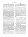
3/1988 Thompson et al. ....... .. 700/219
40
‘(6, COMMON ELEMENTS
42
r _
DEVELOPMENT-SPECIFIC
ELEMENTS
44
US 6,408,429 B1
Page 2
US. PATENT DOCUMENTS
5,133,075 A
7/1992 Risch ....................... .. 707/201
5,136,705 A
8/1992 Stubbs et a1.
.. 714/27
5,166,985 A * 11/1992 Takagi et al.
382/8
5,168,441 A
5,231,675
A
12/1992 Onarheim et a1.
*
5,255,363 A
5,261,043 A
7/1993
Sarr et al.
.........
.. 700/17
. . . . ..
382/8
10/1993 Seyler ...................... .. 707/526
11/1993 Wolber et al. ............ .. 345/809
5,291,587 A
3/1994 Kodosky et a1. ..
5,293,476 A
3/1994 Wolber et al.
5,301,301 A
4/1994 Kodosky et a1. ..
.... .. 703/2
345/763
700/86
5,301,336 A
5,371,690 A
4/1994 Kodosky et a1. .......... .. 345/846
12/1994 Engel et al. .............. .. 382/151
5,475,851 A
12/1995 Kodosky et a1. ..
5,481,712
A
1/1996
5,481,740 A
5,481,741 A
5,497,235 A
5,504,917 A
*
5,576,946 A
Silver et al.
......
345/763
. . . . ..
Algebra and Morphological Image Processing II (1991), pp.
113—124.
D. Scott Dyer, “A Data?ow Toolkit for Visualization”, IEEE
Computer Graphics & Applications (1990), pp. 60—69.
Craig Upson et al., “The Application Visualization System:
A Computational Environment for Scienti?c Visualization”,
IEEE Computer Graphics & Applications (1989), pp. 30—42.
Paul Otto et al., “Design and Implementation Issues in VPL,
AVisual Language For Image Processing”, SPIE vol. 1659
Image Processing and Interchange, (1992), pp. 240—253.
John Rasure et al., “Image Processing and Interchange:
Implementation and Systems”, SPIE vol. 1659 Image Pro
cessing and Interchange, (1992), pp. 300—310.
1/1996 Kodosky ........ ..
345/839
1/1996 McKaskle et a1.
345/522
Michael E. Clarkson, “An Intelligent User Interface for the
3/1996
4/1996
356/430
345/522
Detection of Arbitrary Shapes by Mathematical Morphol
ogy”, SPIE vol. 1769 Image Algebra and Morphological
Image Processing III, (1992), pp. 82—93.
Bell ............... ..
Austin ........ ..
11/1996 Bender et a1.
5,610,828 A
717/1
M. Flicker et al., “An Object—oriented Language for Image
and Vision Execution (OLIVE)”, SPIE vol. 1568 Image
700/17
3/1997 Kodosky et a1. ..
.... .. 717/1
382/110
James Martin, et al., “A Consumer’s Guide to Diagramming
Bell ........... ..
Pearson ...... ..
Kodosky et a1. ..
356/430
700/223
.... .. 717/4
James Martin, et al., “Data Flow Diagrams” Diagramming
5,734,863 A
3/1998 Kodosky et a1. ..
.. 703/27
5,742,504 A
4/ 1998
5,784,275 A
7/1998 Sojoodi et a1.
5,847,953 A
12/1998 Sojoodi et al.
5,659,624 A
*
5,703,688 A
5,703,784 A
5,732,277 A
* 12/1997
* 12/1997
3/1998
5,862,372
A
5,887,073 A
*
Meyer et a1.
.....
. . . .. 700/83
700/86
Techniques”; Diagramming Techniques for Analysts and
Programmers, (1985); Chapter 23, pp. 327—348.
Techniques for Analysts and Programmers, (1985): Chap
ter7, pp. 93—108.
3/1999 Fazzari et a1.
382/110
Tilak Agerwala, et al., “Data Flow Systems”, Computer,
Feb., 1982, pp. 10—14.
“Images” Imaging Technology; Winter 1998; pp. 1—6.
5/1999 Sojoodi et a1.
7/1999 Sojoodi et al.
700/83
700/86
Checkpoint Marketing Materials; Cognex, 1995.
“Cognex Announced On—Sight in Detroit”; Mass High Tech;
700/83
Jul. 1, 1990; pp. 4.
1/1999
5,905,649 A
5,920,479 A
5,940,296
8/1997 Fazzari et a1.
Morris et a1.
.. 700/83
.....
.. ... .. ...
. . . . ..
. . . ..
717/1
A
*
8/1999
Meyer
6,122,065 A
*
9/2000
Gauthier ................... .. 356/394
OTHER PUBLICATIONS
Brown:. “DSP design with DADiSP”, Electronics World +
Wireless World, Dec. 1989, pp. 1152—1154.
Buxbaum:, “Scienti?c/Industrial Image Processing on the
Mac”, Advanced Imaging, Apr. 1991, pp. 22, 24, 26, 28 &
31.
“Reviews”, MacUser, Jul. 1991, pp. 82—87, 89—91.
Mort, et al:, “Low cost image analysis workstation which is
menu driven and extensible”, Medical Imaging IV: Image
Capture and Display, Proceedings, SPIE—The International
Society for Optical Engineering, vol. 1232, pp. 380—385 &
387—389.
Hollinger, et al:, “A Six—Pack for the Mac”, ESD: The
Electronic System Design Magazine, Jun. 1989, pp. 26—28,
30, 32, & 35—37.
Sensor Review: the International Magazine of Sensing for
Industry, vol. 10, No. 4, (2 pgs).
Morris:, “Image processing on the Macintosh”, Product
Reviews, Reader Service, Aug. 1990, pp. 103—107.
“Reviews”, MacUser, Jul. 1990, pp. 55, 57 & 58.
Kleinman: “The Macintosh as a Scienti?c/Industrial Image
“Vision System Offers Power, Easy—Of—Use”, Advanced
Manufacturing Technology, v11, n7, Jul. 15, 1990; pN/A.
“New Players, Different Strategies in Robotics”; Metal
working News; Jun. 18, 1990; p. 5.
Michael Fallon; “New robots and vision systems emphasize
ease of use”; Aug., 1990; Plastics Technology, v36, n8,
p37(4).
Cathy Rossi; “Cognex preps easy—to—use vision system”;
Metalworking News, Jun. 4, 1990; v17, n788, p4(2).
Thompson, et al., Cognex Presentation at New York Society
of Security Analysts; Business Wise, 1990.
Cognex Next—Generation Machine Vision System Com
bines Power With Ease of Use; Jun. 5, 1990 p1.
Alison Calderbank; “Macs Mix Among Robots: Macintosh
developers display their wares” Macintosh News; Jun. 18,
1990; p12.
“Vision System is Easily Con?gured”; Advanced Manufac
turing Technology; Oct. 15, 1990; v11, n10, pN/A.
“Cognex Corp. Establishes Support and Marketing Office in
Japan”; Dec. 3, 1990; News Release p1.
Gary Slutsker, et al.; “The vision thing”; Forbes; Dec. 10,
1990, V146, n13, p284(2).
Mark McLaughlin; “Visions of an Expanding 1991”; Boston
Globe; V238 N183 51 p76.
Processing Platform”, Advanced Imaging, Apr. 1991, (16
“Vision Restored”; Design News; Feb. 25, 1991; p91.
L. G. Shapiro et al., “INSIGHT: A Data?ow Language for
“Cognex Corporation Company Report”; May 4, 1990;
p1—1.
pages).
Programming Vision Algorithms”, IEEE 1986 Computer
Raines Cohen; “GTFS tunes up imaging application, instru
Vision and Pattern Recognition, 1986, pp. 375—380.
A. Meygret et al., “Segmentation of Optical Flow and 3D
Data For the Interpretation of Mobile Objects”, IEEE, 1990,
ment library for Lab View”; MacWeek, v6, n8, p6(1); Feb.
pp. 238—245.
24, 1992.
William B. Ackerman, “Data Flow Languages”, Computer,
Feb., 1982, pp. 15—25.
US 6,408,429 B1
Page 3
Alan L. Davis & Robert M. Keller, “Data FloW Program
“Ultimage User’s Manual”, Image processing and analysis
Graphs”, Computer, Feb., 1982, pp. 26—41.
softWare for the Apple Macintosh II, Graftek France, 1988.
Arvind & Kirn P. GosteloW, “The U—Interpreter”, Computer,
Feb. 1982, pp. 42—49.
D. D. Gajski, et al., “A Second Opinion on Data FloW
Machines and Languages”, Computer, Feb., 1982, pp.
58—69.
Ian Watson & John Gurd, “A Practical Data FloW Com
Steven Rosenthal and Larry Stahlberg, AutornatiX Inc.:
“New Approach to Machine Vision Application Develop
ment”, International Robots & Vision Autornation Confer
ence, 1990; Detriot, Michigan, US.
puter”, Computer, Feb., 1982, pp. 51—57.
AndreW W. Davis & Ari Berrnan, Recognition Technology,
CogneX 4000/5000 SMD PGP Technical Guide Fiducial
Inc.: “Intergratea' Software Package for Machine Vision”
Interantional Electronic Irnaging Exposition & Conference,
1987; Anaheim, California.
Finder, Revision B, CogneX Corporation, Chapter 4—Train
ing a Model, 1995, p. 18.
CogneX 4000/5000 SMD PGP Technical Guide Fiducial
5—Searching for a Fiducial Mark, 1995, pp. 25—35.
The Itran 8000 (Product Brochure), Itran Corporation;
Manchester, NH; 1983.
“IPLab Users’s Guide ”, Signal Analytics Corporation,
1989, 1990, 1991.
* cited by eXarniner
Finder, Revision B, CogneX Corporation, Chapter
U.S. Patent
Jun. 18,2002
Sheet 1 0f 9
US 6,408,429 B1
my. 1
(PRIOR ART)
ARTICLE
INSPECTION
PROCESSOR
U.S. Patent
Jun. 18,2002
Sheet 2 0f 9
US 6,408,429 B1
Q2 NN
x
MN
N
5zo5Ew$m530E2%
~
wm O
Ew90Lz2ao0?m,
5wzamw5~oNm 0
20, o 5
a:mm
6520962é58io-:am
SN
o8o
0
H
8m8W
O"o
o_o
r
lIll
o
N.mQAMPO M<FU
E6200850m
j
a R
P
U.S. Patent
Jun. 18,2002
Sheet 3 of9
US 6,408,429 B1
my. 3
(PRIOR ART)
3
~24
~30
W
'.
2
26
34
32
3
\"" ' '
18b
3
‘ '
2
PROCESSING
SYSTEM
U.S. Patent
Jun. 18,2002
Sheet 4 0f 9
US 6,408,429 B1
O
40, COMMON ELEMENTS
DEVELOPMENT-SPECIFIC!
ELEMENTS
,
GUI
48
DEPLOYMENT-SPECIFIC’ ' <__+
ELEMENTS
Ilu'
5s), COMPUTER-READABLE
MEDIUM
4
P
u
STEP
OBJECT
CONTROL _________.>
FLOW
‘
4
\
\
52
I
1
I
\
54
I
\
\I
ll.\ \\ll1ll
STEP
3: OBJECT
I
,7
l
a
\
II
\\ N-1
‘i
n
2
L
STEP TOOLS
U.S. Patent
Jun. 18,2002
Sheet 5 0f 9
US 6,408,429 B1
350
62
2
-
_
_
_
_
..
_>
7
STEP LIBRARY
''''
STEP OBJECT
8
54
e4
66
2
2
STEP INSTALLER
68
2
USER l/F
STEP TABLE
\_
U.S. Patent
Jun. 18,2002
Sheet 6 0f 9
US 6,408,429 B1
‘
971g. 6
7/0
‘ _______________ _ _>'_ __________ _ _ 1
I ———————————————————————————— - - I
I
I ———————————————————————————— — —I
|
I
l
l
I
I
l
I
I
I
I
STEP TABLE
~ 66
I I I
lI
I
I
I
|
I
I
I
I
I
I
I
I
I
I
I
I
72
‘I
‘I
I I I
IMAGE (FOV)
II II II
I I I
I
I
I
I
I
|
I
I
lI
74
54
‘I
I
2
STEP OBJECT
I I I
CALIBRATION
I
I
I
I
l
DATA
I
I
DEVICE MODEL ~76
I
'I I I
I
I
I
I
I
I
l
I
I
I
I
I
I
I
I
I
l
I
I
I
l_
I_I
I ____________________________ __ _|
78
820
OTHER
82
STEP
INSPECTION
pggég'gs
CONTROLLER
CIBRNQEZALIILAESR
CONTROLLER
2
CENTRAL
CONTROLLER
U.S. Patent
Jun. 18, 2002
Sheet 7 0f 9
US 6,408,429 B1
c
m 7
INSPECTION
~ 86
PRQCESSlNG
SYSTEM
API
GUI
~94
CLI
3
9O
922
ARTICLE PLACEMENT
CONTROL PROCESSOR
U.S. Patent
Jun. 18,2002
Sheet 8 0f 9
US 6,408,429 B1
CONTROL-FLOW
(All Steps)
To Other Steps:
PASSED ——> PASS SID
FAILED ——> FAIL SID
DATA-FLOW
From Other Steps: (Determined by Step Category)
Data SID 1 ——>
Data SID2 -—*-> |NpUT
DATA
.580
J
TO
58b‘ OUTPUT ——>
1
OTHER
DATA
TYPES
TYPES
*
——->
Data SID n ——->
TOOL SPECIFIC
100~ TooI
Model Parameters
Operation Parameters
STEPS
1IIlI‘
U.S. Patent
Jun. 18,2002
Sheet 9 0f 9
US 6,408,429 B1
,‘Fig. 9
s46~
CENTRAL CONTROLLER PROCESSING
‘"vExecute (MODE=RUN or $8)
:
Empty DATA
~S48
Set S = CSID
‘ Reset
Set CSID =
874 ~
S50
BEGIN SID
S76
.
I
NO
Reset All Installed
S ValId?
Tools
YES
s52
I
Set INSPECTION
e~S78
‘
/ STATUS = FAILED
'
Latch T, CFP, CFF,
DF, &1
l
854
T = t;
ABORT
__/
I
‘ DONE
Set INSPECTION
>
STATUS = PASSED
'
Set INSPECTION
»
.
DF valld W T '-’
CSID Category = ?
.
.
Execute T with DATA, I,
and Device Model
S60 584
T STATUS = '2
S86
RUN
Set CSID = CFP
S82
4'
$62
Add TOOL to DATA
866
8538
FA'L
>
l PASS
S70
'
Set S = 1st DF SID
{I
S68
C
t
4'
Add Results
of TOOL
to DATA
'
OperatIon orApplIcatIon
1, OTHER
> Set S = next DF SID
"88°C
l
‘ STATUS = INVALID
.
S58~
4e
CSID Category = 7
F0":
1, OTHER
872890
MODE = 7
set CSID = CFF
SS :
US 6,408,429 B1
1
2
MACHINE VISION SYSTEM FOR
IDENTIFYING AND ASSESSING FEATURES
OF AN ARTICLE
device inspections, front lit chip inspections, and so on.
Further information about such softWare systems and sub
systems is provided in the COGNEX 4000/5000 SMD
Placement Guidance Package User’s Manual Release 3.1,
This is a continuation of application Ser. No. 08/784,406,
?led Jan. 17, 1997.
PN590-1039, Cognex Corporation (1996), the content of
Which is hereby expressly incorporated herein by reference
in its entirety.
BACKGROUND OF THE INVENTION
1. Reservation of Copyright
The disclosure of this patent document contains material
NeW or odd form SMDs Which do not fall into any one of
the categories for Which inspection programs are already
10
Which is subject to copyright protection. The copyright
oWner has no objection to the facsimile reproduction by
anyone of the patent document or the patent disclosure, as it
appears in the US. Patent and Trademark Of?ce patent ?les
or records, but otherWise reserves all copyright rights What
and perfection of a neW inspection program for a neW or
15
2. Field of the Invention
The present invention relates to a machine vision system
SMD into a product, force-?tting an existing inspection
20
parts and/or provide position information for guiding auto
mated manipulations of such parts.
3. Description of Background Information
Machine vision systems play an important role in auto
mated systems. Cameras are used to obtain images of
The complications associated With creating a neW vision
inspection program increase for multiple ?eld of vieW
(MFOV) inspections, i.e., inspections performed using more
25
30
35
the inspection, assembly, and/or handling of various types of
articles, parts, and devices, including automotive parts (e.g.,
In order to accommodate such limitations in the ?eld of
vieW siZe, the scene is divided into several ?elds of vieW. A
scene is an area of physical space, Which may include the
for example, an industrial controller, a robotic arm, or a
positioning table. Such machine vision systems may aid in
than one ?eld of vieW (FOV). The geometry of some devices
Will make it impossible to successfully run an inspection
program using only one FOV, i.e., a single ?eld of vieW
(SFOV). MFOVs are required either When the device is very
large or When the device has ?ne details that must be picked
up in the image data. When the device has ?ne details, the
resolution of the image of the device must remain high,
Which requires that the physical space corresponding to each
?eld of vieW be much smaller than the total device.
articles, and image processing is performed to identify
features of the article. Further image processing may be
performed to identify the article’s position, measure its
dimensions, and/or to check for article defects. Image pro
cessing results may then be used to aid in the control of
automated systems, such as factory equipment, including,
program to accommodate the neW device, or otherWise
mounting (e.g., manually mounting) the SMD.
of an article. The assessments may include determining the
position of one or more features and/or inspecting features
of the object to determine if they conform to a set of
constraints. An aspect of the present invention relates to a
system for developing feature assessment programs. The
resulting programs, When deployed, can be used to inspect
odd-form SMD. NeW inspection programs Will not be imme
diately available Whenever a neW or odd-form SMD
emerges. For this reason, manufacturers or assemblers may
consider delaying the introduction of a neW or odd form
soever.
for identifying and a assessing (i.e., characterizing) features
available require that a neW inspection program be devel
oped. The dif?culty, hoWever, With creating a neW inspection
program is that sophisticated programming skills are
required, and there are usually delays in the development
40
device and a portion of the background, that should be
considered in order to perform a successful inspection. The
scene may comprise the complete device and background
information surrounding the device, or it may comprise only
portions of the device that are needed to perform the
inspection. When the complete scene cannot be captured
With one image Within the ?eld of vieW of a single camera,
fuses, gaskets, and spark plugs), electrical components (e.g.,
connector pins, keyboards, LED, LCD, VFD displays),
medical and pharmaceutical products (e.g., disposable test
While maintaining adequate resolution of the image, the
scene must be divided into several such images or ?elds of
kits, syringes, needles, and date-lot codes), and consumer
products (e.g., raZor blades and ?oppy disks).
vieW called multiple ?elds of vieW (MFOVs).
The lead pitch and other small features of today’s and
Whenever a neW article, part, or device is inspected by a
upcoming SMDs are decreasing in siZe. Such ?ne SMD
given machine vision system, the vision processing compo
nent of the machine vision system Will usually be modi?ed
features Will require higher image resolution, Which Will
and provided With a neW inspection program for the neW
item. The vision processor Will typically include a different
likely cause MFOV inspections to become more common
place.
visual inspection program for each type of device. For
One type of conventional article assessment development
example, a system for automatically assembling (mounting)
system includes standard development softWare provided by
surface-mounted devices (SMDs) may have a vision pro
cessor Which uses a unique visual inspection program for
assessing each SMD as part of the mounting process.
Many SMD placement manufacturers Will use a vision
55
softWare designed to facilitate code development and debug
ging.
processor in their automated SMD placement system, in
order to increase production rates and to accommodate
60
accuracy demands associated With SMDs having dense,
?ne-pitch leads. In such systems, accurate siting of SMDs is
accomplished using a different inspection program for each
type of SMD involved. For example, COGNEX’s SMD
Placement Guidance Package provides unique respective
softWare programs for large-leaded device inspections, front
lit small-leaded device inspections, back lit small-leaded
Cognex, Which includes a library of high-level vision soft
Ware and image processing tools. It also includes system
In order to create a vision-based inspection program With
these COGNEX products, a user Writes a C-language pro
gram that connects the softWare blocks appropriate for a
desired feature identi?cation and assessment.
Another type of development system Which may be used
to create a vision-based system for identifying features of an
65
article and assessing those features is the CHECKPOINT
system, provided by COGNEX. The CHECKPOINT system
uses a graphical user interface for aiding in the development
US 6,408,429 B1
4
3
Instantiate
of vision programs. A developer may utilize the CHECK
POINT interface to combine high-level vision, I/O and
To create an object Which is an instance of a class.
operator interface tools With conventional programming
Library
elements. Such conventional programming elements can
include menu-selected program statements, such as condi
tional statements (If/Then, If/Else), assigning a value or
result of an expression to a variable name (Set/Set
A collection of routines, or a collection of objects,
modules, or other entities Which each comprise one or more
routines.
Module
Acollection of routines and data structures. Amodule Will
Reference), de?ning conditional or iterative looping (For/
While/Break/Next), using or invoking a function, or ending
a function and returning a value (Call/Return), calculating
10
the value of an expression (Calc), jumping to a statement
(Go to/Label), and providing program comments (Notes).
routines, and code (accessible only to the module) Which
facilitates implementation of the routines into the module.
Such program statements are built automatically from a
dialog input box. As these system commands are entered, the
CHECKPOINT system checks the entered commands for
syntax errors. The CHECKPOINT system is also provided
include an interface, Which comprises constants, data types,
variables, and routines accessible by other modules or
Multiple ?eld of vieW (MFOV) inspection
15
With dialog boxes for inputting important tool parameters,
An inspection process performed using more than one
FOV. Partial inspection processes may be performed on each
?eld of vieW, and all partial inspections then combined to
WindoWs for accessing data and functions of the checkpoint
create a ?nal result.
development system, and debugging capabilities. The sys
Object
tem is also provided With a mechanism for simple editing of
a vision routine by using statements to cut, copy, and paste
utilities.
The COGNEX standard development softWare is ?exible
and facilitates the development of inspection programs. On
A variable comprising both routine(s) and data treated
discretely from the routine(s).
Physical Space
A coordinate system using physical units to describe
the other hand, the CHECKPOINT system uses a more 25 features of a device With respect to a reference point that is
simpli?ed user interface and provides more guidance to aid
independent of the device.
in faster and easier development of inspection programs.
Routine
A section of code Which can be invoked (executed) Within
a program being run by a computer.
Scene
Image data corresponding to an area of physical space
used to perform an inspection. Ascene may include all of an
article and a portion of the background.
There is a need for an improved inspection program devel
opment system Which Will be ?exible and sophisticated, and
Will facilitate quicker development of inspection programs
Without requiring a high level of programming pro?ciency.
4. De?nitions of Terms
The folloWing term de?nitions are provided to assist in
conveying an understanding of the various exemplary
35
embodiments and features disclosed herein.
Class
SUMMARY OF THE INVENTION
The present invention is provided to improve upon
machine vision systems for identifying and assessing fea
A data structure descriptive of (de?ning basic attributes
of) objects Which may be instantiated therefrom.
tures of an article. The present invention may be further
Computer-Readable Medium
provided to improve upon systems for developing feature
assessment programs, Which, When deployed, may inspect
parts and/or provide position information for guiding auto
Physical material, including, for example, a disk, tape, a
RAM, a ROM, and so-on for storing computer-readable
information. A computer-readable medium may comprise
one or more data storage media, and, if plural data storage
media are utiliZed, those media may comprise different types
of media.
end, one or more aspects of the present invention may be
45
folloWed in order to bring about one or more speci?c objects
and advantages, such as those noted beloW.
Device Space
A coordinate system using physical units (e.g., microns)
improved easy-to-use system for developing vision-based
mated manipulations of such parts. In order to achieve this
One object of the present invention is to provide an
to describe features of a device With respect to a reference
article assessment programs.
point ?xed With respect to the device.
Field of VieW (FOV) or Single Field of VieW (SFOV)
Image data representing an image obtained by a single
A further object of the present invention may be to
provide such a program development system Which facili
tates the development of versatile and ?exible article assess
ment programs.
image acquisition. Usually, a single ?eld of vieW comprises
image data corresponding to the area of physical space that
55
tating the identi?cation and assessment of features of an
article. Such a method or system may involve the develop
ment of feature assessment programs, Which, When
Image Space
A coordinate system using virtual units (e.g., pixels) to
describe features of a device.
deployed, may inspect articles and/or provide position infor
Install
To set up and prepare for operation. For example, When a
mation for guiding automated manipulation of such articles.
In accordance With one aspect of the present invention, a
step object is installed, it is set up and prepared for opera
tion.
Instance
An object created (by allocating memory therefor) from a
particular class.
The present invention, therefore, may be directed to a
method or system, or one or more parts thereof, for facili
a particular camera acquires as image data.
system may be provided Which comprises, among other
65
elements, a set of step tools from Which a set of step objects
is instantiated. The set of step tools may comprise machine
vision step objects that comprise routines for processing an
image of the article to provide article feature information. A
US 6,408,429 B1
5
6
control How data structure and a data How data structure may
each be provided. The control How data structure charts a
The camera 18a obtains image data corresponding to a
scene Which may include the area encompassing all perti
nent portions of article 11 and the area around article 11. The
resulting image data of the scene is then forWarded to article
How of control among the step objects. The data How data
structure includes a data How connection providing access to
portions of the data How data structure for at least one of
individual accessing and individual de?ning of a data source
5
for a given step object.
BRIEF DESCRIPTION OF THE DRAWINGS
from the conveyor by a diverter 16.
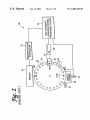
FIG. 2 shoWs an automated system 10b, Which comprises
The above and other objects, features, and advantages of
the present invention are further described in the detailed
description Which folloWs, With reference to the draWings by
Way of non-limiting exemplary embodiments of the present
invention, Wherein like reference numerals represent similar
parts of the present invention throughout the several vieWs
inspection processing system 14 for subsequent inspection
processing. If the article passes the inspection, article 11 is
kept on conveyor 12, for subsequent processing or handling.
HoWever, if the inspection fails, the article may be removed
15
a turret-type SMD mounting system. As shoWn in FIG. 2,
such a system may comprise, among other elements, mount
ing elements, including a turret mounter 24, an SMD feeder
20, and a feeder position controller 22. The illustrated
system further comprises a circuit board X-Y position con
troller 27, an image acquisition subsystem 31, and an SMD
and Wherein:
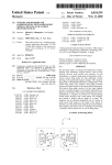
FIG. 1 is a simpli?ed diagram of one type of automated
placement guidance and control processing system 34.
The image acquisition subsystem 31 comprises a mirror
part manipulation system;
assembly 32 and a camera 18b, Which may comprise a CCD
FIG. 2 is a simpli?ed diagram of another type of auto
camera.
mated part manipulation system, i.e., a turret-type SMD
In operation, a circuit board 28 is supported by X-Y board
position controller 27, Which positions circuit board 28 for
mounting system;
FIG. 3 is a side vieW of portions of the SMD mounting
system shoWn in FIG. 2;
mounting of SMDs 26 onto circuit board 28. Feeder 20 feeds
SMDs onto turret mounter 24. Turret mounter 24 supports
FIG. 4 is a block diagram of an exemplary embodiment of 25 each SMD With a vacuum noZZle 30. For that purpose, turret
an integrated inspection program processing system of the
mounter 24 comprises a large number of vacuum noZZles 30
present invention;
periodically positioned about the periphery region of the
The integrated inspection processing system 40 may be
under-side surface of turret mounter 24.
con?gured to have a development mode, in Which a user
may create, debug, and test an inspection program. This
The system illustrated in FIG. 2 may be provided With a
?ducial camera (not shoWn) for obtaining image data used to
might be done by stepping through the intermediate execu
tions of each step object 54 (one inspection step at a time)
identify ?ducial descriptions located on circuit board 28.
and vieWing on a computer screen, e.g., via GUI 48,
intermediate results as they are obtained. The integrated
guiding the placement of the SMDs 26 onto circuit board 28.
inspection processing system 40 may further comprise a
deployment mode, Where the inspection program is
The automated system 10b employs vision processing for
35
may perform such processing functions as system
calibration, failed board identi?cation, board alignment,
device inspection, and placement site location.
deployed and thus behaves like any other SMD SFOV or
MFOV device inspection program.
During system calibration, the image acquisition sub
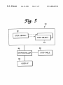
FIG. 5 is a block diagram of an exemplary embodiment of
system 31 obtains an image and the vision processing
component of processing system 34 Will learn the relation
an inspection program development system according to the
present invention;
ship betWeen picture elements (pixels) and physical units.
Images obtained by image acquisition subsystem 31 may
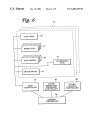
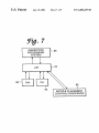
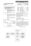
FIG. 6 is a block diagram of an exemplary embodiment of
also be used by the vision processing component of pro
an inspection program deployment system according to the
present invention;
45
another device such as an article placement control proces
sor;
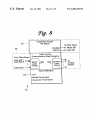
FIG. 8 is a diagram of an exemplary embodiment of an
data obtained by image acquisition subsystem 31. Finally,
instantiated step object; and
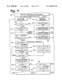
FIG. 9 is a How chart of a process that may be performed
55
Based upon the placement guidance information provided,
the control portion of processing system 34 Will then direct
the manipulation of both SMD 26 and circuit board 28 to
effect mounting of the SMD.
FIG. 3 provides a side vieW of portions of the SMD
mounting system shoWn in FIG. 2. A portion of turret
FIGS. 1—3 illustrate some exemplary automated systems
10a, 10b for processing or otherWise acting upon articles of
a similar type in a repeated and automated fashion. FIG. 1
shoWs an automated system 10a Which comprises a con
to a camera 18a and a diverter 16.
before placement of an SMD on circuit board 28, the precise
site location on circuit board 28 is identi?ed, and the
position of circuit board 28 is guided, as a result of an SMD
position assessment program run by processing system 34.
DETAILED DESCRIPTION OF AN
EXEMPLARY EMBODIMENT
veyor belt 12 supporting a plurality of articles (here, ?oppy
disks) 11. An inspection subsystem 13 is provided as part of
automated system 10a, and comprises, among other
elements, an article inspection processing system 14 coupled
cessing system 34 to identify defects, for example, by
locating marks placed by manufacturers on failed circuit
boards 28, indicating that such boards should not be popu
lated.
Board alignment is performed after the circuit board 28 is
inspected, but before placement of a particular SMD.
Inspection of the SMDs is then performed based upon image
FIG. 7 is a block diagram of an exemplary embodiment
illustrating the interfaces among an inspection processing
system (development and/or deployment), a user, and
by the step controller shoWn in FIG. 6.
A vision processing component of processing system 34
mounter 24 is shoWn, together With a single vacuum noZZle
30 Which is holding an SMD. Image acquisition subsystem
65
31 includes a mirror assembly 32 Which directs light
re?ected off of SMD 26 toWard an image plane of camera
18b.
US 6,408,429 B1
8
7
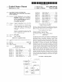
an integrated inspection processing system 40 of the present
On the other hand, if the edge detection routine portion of
the given step object is not determinable, then the type of
invention.
result of that routine Would be a FAIL result, in Which case
FIG. 4 is a block diagram of an exemplary embodiment of
a second folloWing step object may entail modifying or
obtaining neW parameters used to perform that edge detec
Integrated inspection processing system 40 generally
comprises a development-speci?c element 42 (e.g., a special
interface Which aids in the development of an inspection
program), deployment-speci?c elements 44 (e.g., a com
tion.
FIG. 5 is a block diagram of an exemplary embodiment of
an inspection program development system 60. The illus
mand interface Which can be used to control the deployment
trated inspection program development system 60 is shoWn
of inspection programs), and common elements 46.
Common elements 46 comprise such items as a user
10
to comprise a user interface 68, a step installer 64, a step
table 66, a step library 62, and a plurality of step objects 54.
An inspection program development system 60 as illus
interface, for example, a graphical user interface (GUI) 48,
and a computer-readable medium 50 encoded With a pro
gram. The program may comprise a set of step tools 52 from
Which a set of step objects 54 may be instantiated, a control
How data structure 56, and a data How data structure 58.
15 tions taking into account the characteristics of a neW or odd
Step objects 54 comprise, among other elements, machine
vision step objects that comprise routines for processing an
form device to be inspected (such as body and lead
measurements) that are directly measurable from physical
image of an article to provide article feature information.
instances of the device or that may be ascertainable by other
means such as mechanical draWings. The illustrated inspec
trated in FIG. 5 Will alloW a user to easily develop an
inspection program by combining vision processing func
Control ?oW data structure 56 charts a How of control among
Which provides access to portions of control How data
tion program development system 60 Will further facilitate
the designation of the control How betWeen vision process
structure 56 to facilitate at least one of individual accessing
ing functions performed by the inspection program and the
step objects 54, and comprises a control How connection
and individual de?ning of a folloWing step object 54 speci
sources of data used by each vision processing step Within
?ed by control How data structure 56 to folloW a given step
object 54. A plurality (0, 1, . . . N-l) of step objects 54
the resulting inspection program.
More speci?cally, the illustrated inspection program
25
together comprise the general routines and interconnections
development system 60 shoWn in FIG. 5 may alloW a user
needed to perform an inspection program.
to develop an inspection program by specifying such param
eters as:
Data ?oW data structure 58 charts a How of data among
step objects 54, and comprises a data How connection. The
(1) A geometric device model for a target device class.
(2) A set of step objects, instantiated from a set of tools,
Which may comprise a hierarchical tool library. Tools
data How connection provides access to portions of data How
data structure 58 for facilitating at least one of individual
accessing and individual de?ning of a data source for a given
may be categoriZed in accordance With input/output
step object 54.
The set of step tools 52 may facilitate the instantiation of
characteristics (data types). Some tools that are pro
35
other types of step objects, Which do not comprise machine
vision step objects, but rather are management/program ?oW
type of step objects. These management/program ?oW step
objects facilitate the development of an inspection program
and/or they may facilitate the deployment of a resulting
inspection program formed With both machine vision type
(being tools from Which machine vision step objects are
instantiated), While other tools are program How tools
(from Which program How step objects are instantiated)
Which manage transitions to or from machine vision
step objects. Such managing of transitions to or from
machine vision step objects may entail direction of the
How of data and/or control into and out of a system
step objects and management/program ?oW type step
objects.
In other Words, the step tools may comprise machine
vision step tools from Which machine vision step objects are
vided in the library provide machine vision capabilities
deploying the resulting inspection program.
(3) A speci?cation of the control How betWeen step
45
instantiated and program How step tools from Which pro
gram ?oW step objects are instantiated. The machine vision
objects, based upon the execution-time success or
failure of each step object.
(4) A speci?cation of the data How betWeen instantiated
step objects, in accordance With tool category input/
output data types.
step objects may comprise routines for processing an image
of the article to provide article feature information, While the
program How step objects comprise routines for managing
An inspection program may be developed by specifying
transitions to or from the machine vision step objects.
In order to facilitate the How betWeen step objects, so that
the end deployment of a resulting inspection program is not
these types of information. More speci?cally, a user may
limited to a particular ordering of the step objects, the How
of control may be speci?ed by separately specifying for a
interact With user interface 68 and install each step object by
specifying its parameters Within a step table 66. Such
parameters may include control-?oW information, data-?oW
given individual step object a ?rst folloWing step object for
information, device model information, and tool parameters.
The inspection program development program 60 shoWn
one type of result of a routine of the given step object and
a second folloWing step object for another type of result of
in FIG. 5 may operate as folloWs. Step library 62 may
comprise a variety of both machine vision and program How
the routine of the given step object.
In the speci?c embodiment illustrated herein, the ?rst type
tools, instances of Which are available for installment as
of result is a FAIL result, While the second type of result is
a PASS result. By Way of example, an edge detection routine
may be performed as part of a particular machine vision step
installer 64 may receive inspection step installation com
55
object. If the edge detection performed by that step object
results in a successful determination of an edge, the result 65
Would be a PASS type of result, and the ?rst folloWing step
object could be de?ned as a neW machine vision step object.
inspection steps into step table 66 by step installer 64. Step
mands originating from user interface 68, Which specify
particular tools Within step library 62 to be installed,
together With control ?oW information, data ?oW
information, and operational and model parameters corre
sponding to each speci?ed tool to be installed. Upon receiv
ing such a command, and the accompanying information,
US 6,408,429 B1
10
step installer 64 creates an instance of a speci?ed tool in the
Other inspection programs controller 80 may comprise a
form of a step object 54, and as part of installing that tool,
mechanism for controlling the deployment of other standard
inspection programs, for example, inspection programs that
places information identifying the instantiated step object
together With other speci?ed data (control-?oW information,
data-?oW information, operational and model parameters)
are commercially available and direct the inspection of
standard devices. For example, such standard inspection
programs may comprise softWare programs for large-leaded
device inspections, front lit small-leaded device inspections,
back lit small-leaded device inspections, front lit chip
into step table 66.
Each instantiated step object 54 may be uniquely identi
?ed (indexed) by an inspection step ID (SID). An SID may
inspections, and so on, depending upon the types of devices
identify a tool category, to be de?ned further hereinbeloW,
together With an index value, such as a number. Data ?oW
10
being handled by the overall automated system.
information and control How information may be speci?ed
in step table 66 in the form of providing an SID representing
the identity of a step from Which data for the present step
object Will originate, While control How information may be
the handling and manipulation of the device. For example,
should the automated system comprise an SMD mounting
speci?ed in step table 66 by specifying an identi?cation,
15 ler 82 may facilitate the gathering of an SMD onto a vacuum
SID, of a step object to Which the control How Will proceed
depending upon the result of execution of the functions of
noZZle 30 and subsequent mounting of SMD 26 onto a
that given step object. Step installer 64 Will also provide
Central controller 84 may be provided to control the
overall operation of each of the categories of programs
Other process controller 82 may control processes such as
system generally as shoWn in FIG. 2, other process control
circuit board 28 With the use of a turret mounter 24.
identifying information, in the form of a model index, for
each instantiated step object.
Step installer 64 may also be con?gured to respond to
inspection step inquiry commands originating from user
interface 68. Such an inquiry command Would specify the
SID being inquired about. Step installer 64 may respond to
the speci?ed SID by extracting from step table 66 control
?oW SIDs, data-?oW SIDs, and operational and model
parameters for the installed step object corresponding to that
SID. In addition, step installer 64 may be provided With a
mechanism for deleting installed step objects from step table
66, in response to an appropriate request or command, Which
handled by step controller 78, other inspection programs
controller 80, and other process controller 82, respectively.
Central controller 84 may further serve as an interface point
through Which a user can control operation of the entire
system, turn the system on or off, and otherWise adjust
25 parameters before, during, or after operation of one or more
pieces of the overall system.
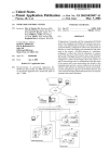
FIG. 7 is a block diagram of an exemplary embodiment
Which illustrates the interfaces among an inspection pro
cessing system 86 (Which may comprise a development
and/or deployment system) and a user and/or another device,
may originate from user interface 68 or from elseWhere.
FIG. 6 is a block diagram of an exemplary embodiment of
such as an article placement control processor 92. The
an inspection program deployment system 70. The illus
trated inspection program deployment system 70 is shoWn to
system 86 coupled to an application program interface (API)
comprise one or a plurality of deployments Which may be
system shoWn in FIG. 7 includes an inspection processing
35
94. A graphical user interface (GUI) 88 and a command line
interface (CLI) 90, are each coupled to a text-based (or other
implemented Within a given computer system, and they may
code-type (e.g., binary code)) API 94. An article placement
comprise softWare program residing on a computer-readable
medium. Each deployment may comprise, among other
elements, a step table 66, image data (comprising one or
more ?elds of vieW) 72, and a set of instantiated step objects
54. Calibration data 74 and device model information 76
may also be provided, but may be put in a central location
common to all of the deployments of the deployment
control processor 92 is further coupled to API 94.
system.
These plural deployments may comprise different inspec
The interface betWeen inspection processing system 86
and API 94 may be a command/response type of interface.
Similar command/response interfaces may be provided
betWeen API 94 and GUI 88, CLI 90, and article placement
control processor 92, respectively. The speci?c embodiment
illustrated in FIG. 7 illustrates such interfaces With the use
of bidirectional arroWs.
45
API 94 may comprise a command/response processor, or
tion programs Which together are used in an overall article
an API such as the SAPP interface Which is a product
inspection and manipulation system.
commercially provided by COGNEX.
The deployments of the inspection programs are coupled
to a step controller 78, Which is in turn connected to a central
controller 84. Central controller 84 is further connected to
TWo alternate types of user interfaces may be provided,
including GUI 88 and CLI 90. GUI 88 may comprise a
sophisticated graphical user interface Which makes it easier
other inspection programs controller 80 and other process
controller 82.
ment of an inspection program in a sophisticated manner, but
Step controller 78 receives inspection commands from
central controller 84 and relays inspection data from the
understand. On the other hand, should just simple command
inspection program back to central controller 84. It may
further control the execution of the inspection steps as
to develop inspection programs, and to control the deploy
in a manner Which is more simple and easier for the user to
55
line interface be suf?cient to control the deployment of an
already-developed inspection program, a simple CLI 90 may
speci?ed in the set of step objects 54, While using other
information in step table 66, image data 72, calibration data
be used.
A CLI 90 may comprise a common CLI Which already
74, and device model information 76. It Will control execu
tion of an inspection program in accordance With step
exists in many present-day mounting systems and other
types of automated systems. Accordingly, an already
objects 54 and control-?oW and data-?oW SIDs speci?ed in
step table 66. Step controller 78 further receives FOV data
from image data 72 Which may be created using an image
acquisition system together With calibration data 74. The
device model relevant to a particular deployed inspection
program may be speci?cally identi?ed in step table 66, as
noted above.
existing CLI can be used to turn on and control deployment
of the custom-created inspection programs created With the
use of the inspection processing system 86 of the present
invention, While using that same CLI is also used to control
65
and turn on other inspection programs and processes asso
ciated With the inspection and manipulation of an article.
API 94 further acts as a generic intermediary betWeen
US 6,408,429 B1
11
12
inspection processing system 86 and an article placement
PASS SID: The inspection step ID of the inspection step
containing the step object to execute after the present
step object corresponding to the current inspection step
control processor 92, Which may use a particular type of
interfacing protocol for interacting With an inspection pro
cessing system, Whether the inspection processing system be
has ?nished executing and has resulted in a PASS
result.
an inspection program development system and/or an
FAIL SID: The inspection step ID of the inspection step
containing the step object to execute after the step
object corresponding to the current inspection step has
inspection program deployment system.
The CLI 90 may be con?gured so that it can interpret
specialiZed ASCII or binary commands, While the GUI 88
may be con?gured so that it can interpret graphical and/or
?nished executing and has resulted in a FAIL result.
The data ?oW betWeen inspection steps may also be
textual inputs.
speci?ed on a step-by-step basis, With the use of the data
?oW data structure 58 of the illustrated embodiment. The
user may name, at installation time, each of the inspection
FIG. 8 is a diagram of an exemplary embodiment of the
overall structure of an instantiated step object 54. Instanti
ated step object 54 may comprise, among other elements, a
control ?oW data structure 56, a data ?oW data structure 58,
and a tool speci?c data structure 100. Control ?oW data
structure 56 may be designed so that it is of similar con
15
steps that Will provide the installed inspection step With its
required input data. The system may be implemented so that
one data originating inspection step is identi?ed for each
input of the present step object. Of course, only certain step
struction for all tools Within step library 62.
As shoWn in the exemplary embodiment of FIG. 8, the
objects (inspection steps) Will be alloWable “data providers”
control ?oW data structure 56 comprises tWo control ?oW
directions, including a PASS control ?oW direction
indicator, and a FAIL control ?oW direction indicator. Those
use of an input data type data structure 58a.
As Was noted above for control ?oW, a data-?oW graph
for any given input data type, Which Will be speci?ed With
may be created, for example, With an appropriate application
program together With a graphically used interface, identi
fying inspection steps as nodes, and data connections With,
control ?oW directions are identi?ed With the use of a PASS
SID and a FAIL SID Which identify respective ?rst and
second folloWing step objects to Which the control ?oW Will
move in execution of the inspection program. Data ?oW data
structure 58 is shoWn in the example embodiment of FIG. 8
for example, arcs. Such a graph may serve as a diagnostic
25
feedback to the user for graphically vieWing an inspection
program, or even a graphical mechanism for specifying the
that information may be identi?ed With the use of SIDs
?oW of data by alloWing the user to graphically connect
inspection steps to each other.
corresponding to other step objects from Which data is
obtained for the present step object 54.
shoWn in the speci?c illustrated embodiment, makes it
as comprising information identifying input data types, and
This ?exible data ?oW data structure, for example, as
possible to share both tools and data across different FOVs.
It also alloWs more ef?cient implementations of both retry
Data ?oW data structure 58 further includes a data struc
ture for identifying input data types 58a, and another data
structure for identifying output data types 58b. The output
and iterative strategies (for example, using a REPEAT tool,
described later herein). In addition, the ?exible illustrated
data types Will then serve as input data for other step objects
54, should another step object 54 identify, by identifying a
35
data ?oW data structure 58 alloWs inspection programs to
conserve memory resources, by alloWing tool output data to
data type and an SID, that particular data as its input.
be removed With the use of a data ?oW or other type of
The step objects of the present invention, for example as
shoWn in the example embodiment of FIG. 8, may include
three main categories of information, including control ?oW
information, data ?oW information, and tool parameters.
The control ?oW controls the ?oW betWeen step objects,
management step object (e.g., a CLEAR tool, as described
later herein). The data ?oW data structure of the embodiment
shoWn in FIG. 8 may be de?ned as folloWs.
The requirements of such a data ?oW data structure may
vary according to the tool category Within Which the present
step object resides. A string of data SIDs may be speci?ed
and may be speci?ed on a step-by-step basis. The user may
identify, at installation time, the next step to be executed,
depended upon the execution result of the present step object
54. Accordingly, the ?oW of control betWeen step objects
to identify the data sources Which Will serve as the various
inputs to the present step object. Such a string of identi?ers
45 may be in the form of Data SID 1, . . . , Data SID n. These
are the ordered inspection step IDs of the inspection steps
containing the tools from Which the tool contained Within
the current inspection step obtains its input. One such SID
may be speci?ed for each of the n data inputs required by the
tool contained in the current inspection step. Only SIDs for
may be speci?ed in a manner comparable to a “state
machine,” Which can be represented by or With the use of a
control ?oW graph, or a comparable simpli?ed mechanism
using a graphical user interface. Such a control ?oW graph
could provide diagnostic feedback to a user While an inspec
tion program is under development. It could also provide a
steps containing tools that are capable of providing input of
graphical mechanism for specifying the ?oW of control by
the appropriate types for the tool contained in the current
alloWing the user to graphically connect the inspection steps.
This ?exible control ?oW data structure makes it possible
step are considered valid data SIDs.
Each installed step object Will also have a set of param
55 eters that governs its execution. Some of these parameters
to ef?ciently implement retry strategies (inspection steps to
may pertain directly to the operation performed by the step
objects. Others may implicitly describe geometric model
perform in the event any of the inspection steps of a given
strategy fail) for both SFOV and MFOV inspection, by
specifying control tree structures. It also makes it possible to
data not contained in a device model. For example, mea
implement iterative strategies, forming control loops Which
surements for the siZe of certain regions of the image may
be required for some tools, and may be speci?ed in terms of
minimum, nominal and maximum siZes of device regions in
the device model. Thus, model data may be Widely distrib
uted throughout a developed inspection program. An inter
could be executed during deployment of a resulting inspec
tion program. Finally, this control ?oW data structure can
facilitate the implementation of either open loop or closed
loop MFOV inspection programs. Open-loop and closed
loop MFOV inspection programs Will be further explained
hereinbeloW.
In the speci?c embodiment illustrated herein, the control
?oW may be speci?ed as folloWs:
active graphical user interface may be provided to aid a user
65
in setting up device coordinate space parameters for each
tool, by graphically displaying geometric parameters in
device space.
US 6,408,429 B1
13
14
Tool speci?c information may be provided in the form of
a tool speci?c data structure 100, and may be unique for each
particular tool. Such a tool speci?c data structure may
During execution of an inspection program, images rep
resentative of the article being inspected may be obtained,
e.g., by an image acquisition system controlled by central
controller 84. Accordingly, in the illustrated embodiment,
central controller 84 (Which may be a mounter program) Will
communicate With the inspection program via step controller
78, and Will provide image data to the inspection program as
it executes its various steps in deployment of the inspection
comprise the following information:
Tool: At installation time, the name of the desired tool
must be speci?ed. From this name (and model and
operational parameters described beloW) step installer
64 (see FIG. 5) may be able to construct an instance of
a step object from step library 62, and place that
instance Within step Table 66.
Model parameters: Certain tools may require information
program.
10
(e.g., indices) indicating portions of a central/target
deployment system 70, stored in image data section 72, and
device model (if any) Which the inspection tool Will
attempt to use. If a tool does not require a device model,
or requires an entire device model, no parameter indi
ces may be necessary.
15
Operational parameters: These parameters may simply
comprise “other” parameters needed to adjust perfor
controller 78, a next FOV during the execution of an MFOV
inspection program, it may or may not suggest to central
controller 84 a particular FOV position (e.g., in physical
space). Central controller 84 Will control the image acqui
The user interface 68 of an inspection program develop
ment system 60, as shoWn in FIG. 5, may be provided With
sition system (not shoWn in FIG. 6) to obtain that next FOV
data and forWard the same back to inspection program
a mechanism for preventing the entering of illegal data,
25
model data, and invalid device parameters, including model
parameters and operational parameters. Such checking may
be performed -on a step object by step object basis during
MFOV inspection programs may be con?gured to execute
Independent Open-loop Mode
In this mode, the image tiling sequence may be com
pletely determined by a central controller 84. Central con
reset, or executed, in order to alloW a user to build a
complete inspection program incrementally.
troller 84 may acquire all of the ?elds of vieW (FOVs) before
executing the inspection program, in Which case the inspec
As shoWn in FIG. 6, a device model 76 may be provided,
and may comprise geometric model data, preferably speci
35
tion program Will execute to completion. In the alternative,
central controller 84 may aWait the processing of each FOV
by the inspection program before acquiring a next FOV,
Which Will cause control to pass back and forth betWeen step
be de?ned by the user before con?guring the inspection
program. This may be done by simply providing a calibra
tion object and an initial device position estimate at
execution-time. The device model may include tool-speci?c
model data particular to certain steps forming the inspection
program, and global geometric model data, such as body
siZe, and lead location and siZe. The tool-speci?c model data
may be implicitly contained Within each of the step objects
for each tool, and they may be directly speci?ed by tool
parameters corresponding to each step object. The global
deployment system 70 for storage in image data section 72
and for use by step objects 54.
any of a number of Ways, e.g., as folloWs:
the development of the inspection program, or may be
deferred until a complete inspection program is created, and
?ed in device coordinate space. There may be some physical
and image coordinate space parameters that are also pro
vided in some instances. The device coordinate space may
acted upon in accordance With the step objects 54. HoWever,
if a multiple ?eld of vieW (MFOV) inspection program is
being deployed, MFOVs Will be provided on a per FOV
basis by central controller 84 to step controller 78 and thus
to the inspection program deployment system 70. When the
inspection program deployment system 70 requests, via step
mance of the tool, or needed by the tool but not
normally otherWise provided. These parameters may
determine, for example, hoW the installed tool should
precisely behave.
including invalid control How or data How data, invalid
When a single ?eld of vieW (SFOV) inspection program
is executed, an SFOV is provided to the inspection program
controller 78 and central controller 84. If the inspection
program deployment system 70 is being implemented in an
overall SMD mounting system, the mounter can be moved
and/or FOV data can be acquired from a camera. It is
important that central controller 84 facilitate a tiling
sequence that is commensurate With a particular inspection
45
geometric model data may be assembled by the user, all at
strategy.
Dependent Open-loop Mode
In this mode, the image tiling sequence is completely
determined by the inspection program, but the suggested
positions of each FOV acquisition do not depend upon the
current device position estimate, since they are speci?ed in
once, or in parts, and kept in a central location called a
device model, such as device model 76 as shoWn in FIG. 6.
This central device model structure 76 Will facilitate the
physical coordinate space at installation time. When control
sharing of device model data by different tools in the
is passed from the inspection program deployment system
inspection program, thus saving on memory and on the
70 to central controller 84, central controller 84 uses the
con?guration time needed for each of the tools.
suggested FOV provided by inspection program deployment
A GUI may be con?gured so that users can vieW and
interactively change a device model. Such a GUI may
55
contain a graphical editor as Well as a numerical editor, and
may alloW a user to draW and graphically modify represen
tations of a device model in device coordinate space (or
system 70 to acquire a next FOV data. This mode of
execution is convenient, since it alloWs even a ?xed tiling
sequence to be contained in the inspection program, and
relieves the requirement that central processor 84, or another
external processor, have knoWledge about the inspection
other coordinates), the results of Which may be automati
cally transferred in parameters necessary to install a central
device model.
strategy.
Closed-loop Mode
As shoWn in FIG. 6, a central controller 84 may be
provided Which manages the overall execution of an inspec
tion program through the use of step controller 78. Such a
central controller 84 may comprise a system Which forms
part of an automated mounting or article manipulation
pletely determined by inspection program deployment sys
system.
In this mode, the image tiling sequence is again com
tem 70, but the suggested positions Will depend upon the
65
state of the inspection program execution, since the sug
gested position of a next FOV is speci?ed in device coor
dinate space at installation time, Which is converted into
physical coordinate space at execution time using the current
US 6,408,429 B1
15
16
estimate of the device’s position. This mode may be espe
from the image acquisition system to the appropriate
installed FOV tool, simply by specifying the SID for the
corresponding installed step. Upon return of control from
this other entity (e.g., central controller 84) to step controller
cially useful When the optimal tiling strategy depends upon
the status of the inspection program, and When another
external system, such as a mounting system, has the ability
described MFOV tiling strategies may be chosen on a per
78, execution may resume at the step containing the FOV
tool, Where it left off.
In terms of data ?oW, FOV tools are the keepers of their
associated FOV data, and therefore may provide image-type
FOV basis, due, in part, to the step-by-step manner in Which
data to other installed tools.
to move an image acquisition camera to various locations.
Hybrid combinations of the closed-loop and open-loop
modes may be possible. For example, each of the above
In addition, the BEGIN FOV tool may specify the starting
a set of step objects may be de?ned to create an inspection
program in the illustrated embodiment of the present inven
tion.
TABLE 1 exempli?es some of the tools that may form a
step library 62, for example, as shoWn in FIG. 5. All of the
tools provided in TABLE 1 are arranged hierarchically. At
the top level of the hierarchy, all tools in the tool library
point in an inspection program for a ?rst FOV during an
MFOV inspection, or a data entry point for image data
during an SFOV inspection. This BEGIN FOV tool may be
automatically installed When the inspection program is
15
contain a status, Which is PASSED if it has executed since
the last reset condition and Was able to compute the infor
table, Will thus typically alWays originate from the installed
mation that it has been con?gured to provide, and FAILED
BEGIN FOV tool, folloWing an inspection or Whenever the
inspection program is started or an inspection program reset
and execution command is provided to inspection program
otherWise. Some error code and appropriate message may be
provided in the event of a FAIL status. Beyond this
deployment system 70. The inspection program develop
commonality, tools may be grouped into categories accord
ing to What they require for input and What provide as
output.
In the illustrated embodiment, all inspection tools of a
ment system 60, as shoWn in FIG. 5, may be implemented
so that the BEGIN tool may never be deleted, but may be
25
particular category require a number of inputs and provide
a number of outputs With particular data types. Data types
may include, for example, image data (an image and a
calibration betWeen image and physical coordinate spaces),
threshold data (a grey scale threshold value), position data
(an estimate of a device position in physical coordinate
space), and feature data (features extracted from images With
or Without correspondences to model features).
Within each tool category, the tool library (step library)
may offer a variety of different tools. Some examples are
created, and there should be a need for only one BEGIN
FOV tool per inspection program.
The How of control, as speci?ed, for example, by a step
replaced With another step containing a BEGIN tool so that
the control-?oW con?guration may be altered to specify the
desired next inspection step to execute in the inspection
program.
For an MFOV inspection, an inspection step containing a
NEXT FOV tool may be manually installed by a user for
each ?eld-of-vieW beyond the ?rst.
Termination tools serve as ?nal data and control How exit
points from an inspection program. They may permanently
35
given in TABLE 1. Some of the tools provided in TABLE 1
comprise machine vision tools, While others are program
How tools, for example, data How or program handling tools,
Which provide data How or control How functionality for
interfacing betWeen an inspection program deployment sys
return control from an inspection program deployment sys
tem 70 to another entity, such as central controller 84, along
With the ?nal results of an inspection program execution.
Like the BEGIN FOV tool, termination tools may be auto
matically installed When the inspection program is created,
and there Will only be a need for one of each type of
termination tool per inspection program.
tem 70 and a central controller 84, for example, as shoWn in
FIG. 6. Such program How tools include, in the illustrated
The How control may be set so that it alWays returns to a
common entity, such as central controller 84, from an
embodiment, ?eld of vieW (FOV), Termination, Application,
and Operation categories (listed under the tool category).
passing inspections. For failing inspections, the How of
These program How tools may include such tools as BEGIN,
inspection step containing a DONE termination tool for
45
NEXT, DONE, ABORT, REPEAT, and CLEAR tools, Which
control may alWays return from the inspection step contain
ing the ABORT tool.
are listed under Available Tools. These program How tools
Each application tool may be con?gured so that it must be
provide signi?cant advantages to an inspection program
developed in accordance With the embodiment provided
manually installed by the user. Such application tools
execute a version of a vision tool contained in another
installed inspection step, at an entirely different point in the
inspection program, and With its oWn independent control
and data How speci?cations. The input for application tools
may comprise the tool to be applied, in addition to the data
herein, are described in TABLE 2, and are further described
as folloWs.
The ?eld-of-vieW (FOV) tools serve both control and data
How functions betWeen the inspection program and an
required for the applied tool.
external entity, such as a central processor 84 as shoWn in
FIG. 6. Each of these tools represents the control and data
55
A REPEAT application tool may be provided Which
How entry point into the inspection program folloWing the
acquisition of data (comprising image and calibration
information) for a particular FOV in an image tiling
tool-speci?c installation parameters. This application tool is
particularly useful for repeating tools in different ?elds of
sequence.
vieW.
executes an installed tool Without any modi?cations in the
Each operation tool may comprise steps Which require
Installed FOV tools alloW control to be temporarily
passed back to another entity, such as a central controller 84,
if necessary, in order to obtain data for the associated FOV
in the image tiling sequence. In this situation, an FOV tool
may provide a suggestion to the other entity for positioning
the mounter/camera during the acquisition process. At this
manual installation, and may perform some sort of operation
on another vision tool contained in an installed inspection
65
step. The input for operation tools may simply be a tool to
be operated upon. The CLEAR operation tool resets the
“state” of another installed tool, thereby freeing any result
time, or at any time in Which another processor such as a
data associated With the other installed tool and any memory
central controller 84 has control, FOV data can be routed
used to store that data.