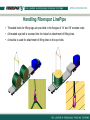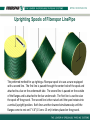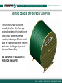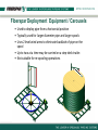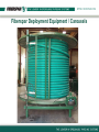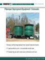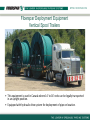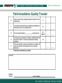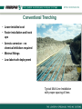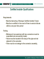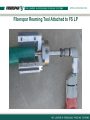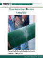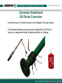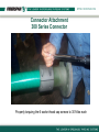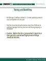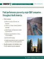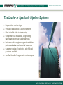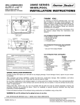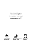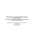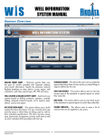
1
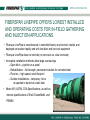
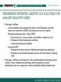
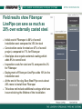
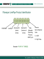
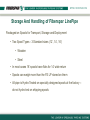
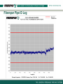
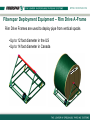
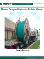
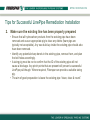
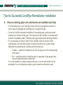
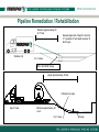
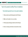
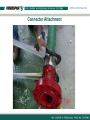
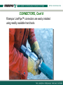
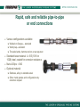
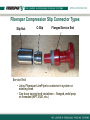
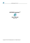
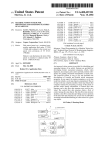
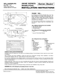
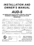
Fiberspar LinePipe The Leader In Spoolable Pipeline Systems TM “Full Reel” Program Certified Installer Training Tuesday, December 07, 2010 INTRODUCTION TO FIBERSPAR • Founded in 1986 as a spin-off from Massachusetts Institute of Technology • Market leader in high tech sporting goods from advanced composite materials from 1989 –2000 (Sold Division to concentrate on oilfield products) – Fiberspar products used to win 12 successive world championships in windsurfing, 3 consecutive National Hockey League scoring titles, and 3 America’s Cup Yacht Races • Development of patented Spoolable Pipe undertaken with the participation of major oil field participants – Conoco, Halliburton, and Weatherford. • Between 2003 – 2009, nearly 25 million feet of Fiberspar LinePipe installed for in field gathering service in North America, for more than 500 operators. • LinePipe offered between 2 ½”– 6 ½”, in 300psi, 750psi, 1,500psi, and 2,500psi operating pressures. FIBERSPAR LINEPIPE OFFERS LOWEST INSTALLED AND OPERATING COSTS FOR IN-FIELD GATHERING AND INJECTION APPLICATIONS • Fiberspar LinePipe is manufactured in controlled factory environment, tested, and deployed on location rapidly and with low labor and low cost equipment • Fiberspar LinePipe does not corrode (no corrosion vs. slow corrosion) • Innovative installation methods allow large cost savings – Open ditch – pipeline on a spool – Rehabilitation – full strength, permanent solution for corroded steel – Plow Ins – high speed, small footprint – Surface Installations – temporary, to be re-spooled or buried at a later date • Meets API, ASTM, CSA Specifications, as well as internal specifications of Shell, ExxonMobil, and PEMEX FIBERSPAR’S PATENTED LINEPIPE IS A SOLUTION FOR A MAJOR INDUSTRY NEED • Fiberspar LinePipe: – Lower installed costs compared to steel or stick fiberglass, and this lowers our customers CAPEX and improves returns on capital – Reduced operating costs – lower OPEX • No corrosion vs. slow corrosion (no inhibitors, inspection, etc.) • Reduced in-field maintenance activities • Improved uptime and reliability – Improved HSE • Reduced loss time injuries in facilities and pipelining operations • Reduced environmental and land owner costs from failed or leaking lines • Fiberspar LinePipe is a field proven, fully qualified pipeline technology which results in lower installed and operating costs compared to current alternatives, and can uniquely be used to rehabilitate failing infrastructure Field results show Fiberspar LinePipe can save as much as 20% over externally coated steel. Initial cost of Fiberspar is 60% of overall installation cost compared to 35% for steel Construction costs for steel are 47% of overall project, compared to 17% for Fiberspar Steel pipe also requires external coating which adds 9% to overall cost Inspection costs for steel are 5% compared to 2% for Fiberspar Deployment of Fiberspar LinePipe adds 10% to the installation cost At the end of the day, Bare Steel Pipe costs about 20% more to install than Fiberspar This does not include additional savings which are incurred during the lifetime of the installation Faster, easier installation – less than half the time with less manpower and equipment Projects staged at our deployment centers and delivered installation ready Long lengths (610 feet up to 9,000 feet) with minimal joints or connectors to reduce pipe handling and to expedite installation Light weight for improved safety and speed of installation No welds, coatings or x-ray inspections required Fiberspar Field Technician on location to operate specialized equipment, and to provide expert, continuous on-site support Projects on-stream faster FIBERSPAR LINEPIPE CAN BE USED FOR ALL OILFIELD APPLICATIONS Applications • • • • • Gas or oil gathering Water disposal Gas injection Water injection CO2 injection Installation Methods • • • • Conventional trench Surface Lay Plow-in Rehabilitation Typical Multi-Line Installation Note lack of separation of lines Fiberspar LinePipe has been installed in all types of environments • Over 500 end-user customers • Nearly Every Major E&P Company has used or is using Fiberspar LinePipe • Includes ExxonMobil, Shell, BP, ConocoPhillips, Chevron, Encana, Anadarko, PennWest, Apache, PEMEX • Installed in all kind of conditions including very low temperatures • The design, manufacturing process and materials used are virtually unchanged over the last several years • The pipe is manufactured on a highly automated process in a modern factory with excellent quality assurance practices FIBERSPAR IS THE MARKET LEADER IN SPOOLABLE HIGH PRESSURE LINEPIPE 1st Commercial Installation in 1999 in West Texas • Initially installed 40,000’ of 2 ½”-1500(E) for a Saltwater injection/waterflood system • Injection pressures began increasing during the first year and as a result, the customer was overpressuring the product • Replaced 38,000 ft (8,500m) with 2,500 psi, 297 fittings • Continuous operation through present – over 10 years in continuous service FIBERSPAR IS THE MARKET LEADER IN SPOOLABLE HIGH PRESSURE LINEPIPE Nearly 3.5 Million feet installed inside of failed steel lines • More than 1,500 rehabilitation jobs • Mix of emulsion, water, gas and some in sour service FIBERSPAR MANUFACTURING PLANT •Fully automated process lines •Capacity 10 million feet/ year (future 13.5 mm) •Expansion to include 4th production line Fiberspar LinePipe is manufactured in a state-of-the-art facility • Production capability for 1” to 6” nominal ID • Continuous lengths to 36,000 ft • Full statistical process control, in-line marking, serialization • Liner and Jacket extrusion inhouse • Fiber reinforcement process lines • climate controlled • Line speeds from 9-12ft /minute depending on pipe size • Includes in- line curing Innovative technology – more than 25 million feet (7.6 million meters) installed Exclusive and unique patented design Temperature rated from −29°F (-34°C) to 140°F or 180°F (82°C) continuous operation Full range of sizes – 2 1/2” to 6 1/2” plus custom diameters Full range of operating pressures – 300 to 2500 psi plus custom pressures 21 US and Canadian patents Meets or exceeds the flow rates of conventional steel lines of comparable diameter Wear resistant outer jacket Unique integrally bonded structure Various Layers in Fiberspar LinePipe Polyethylene Inner Liner Epoxy and Fiberglass Laminate Outer Poly Jacket Fiberspar LinePipe Product Identification FIBERSPAR LinePipeTM Nominal OD (whole inches) Nominal OD (fraction of inches) Max. Allowable Operating Pressure, MAOP, (psi) Example: FS LPJ 3 ½” 1500 (E) Pressure Barrier Material Code: E = HDPE X = High Temp. Fiberspar LinePipe Connector Identification Connector Design Revision Series: A = 300 Series B = 750 Series C = 750 Series D = 1000 Series E = 1500 Series End Termination Size: Nominal OD End Termination: X = Whole Inches W = Flanged Assembly Z = Nominal Pipe Size in Inches x = decimal parts of an inch L = NPT Threaded Assembly z = ANSI Flange Rating 0=150 Series F = 2250 Series 1=300 Series G = 2500 Series 2= 600 Series Example: CLE35W32 3=900 Series (3 ½” Service End with 3” ANSI 600 Flange) 4=1500 Series FIBERSPAR CONNECTORS • Full Strength – Burst, Tension – Max. Rated Temp. • Rapid Field Installation (30 minutes or less typical) • Welded on flanges, threaded ends, hammer unions or other fittings as required. • Wetted surface coated to resist corrosion Storage and Handling of Fiberspar LinePipe Storage And Handling of Fiberspar LinePipe Packaged on Spools for Transport, Storage and Deployment • Two Spool Types - 3 Standard sizes (12’, 14’, 16’) • Wooden • Steel • In most cases 16’ spools have flats for 14’ wide return • Spools can weigh more than the FS LP stored on them • All pipe is Hydro-Tested on specially designed spools at the factory – do not hydro-test on shipping spools Fiberspar Pipe OD Log Fiberspar Pipe ID Log Handling Fiberspar LinePipe Caution: FS LP wound on spools has some stored energy. Ensure that the pipe end is restrained during all operations to avoid rapid release of this energy and potential injury to personnel and damage to pipe and equipment. Handling Fiberspar LinePipe Handling Fiberspar LinePipe Handling Fiberspar LinePipe Caution: Improper handling of spools of FS LP can result in personal injury as well as damage to the product. Ensure that the lifting equipment used, including straps, slings and spreader bars are in good working condition and are rated for the load and conditions. Tools / Equipment Required •A mechanical lifting device (e.g., a forklift or crane) •Spreader bar with properly rated chains or cables and shackles •Taglines •Personal Protective Equipment •Two-Way Radios (optional) •Detailed procedures are outlined in the manual under “Procedure for Spool Handling” Handling Fiberspar LinePipe • Normally transported to location already on spooling equipment • Specialized equipment is used to minimize spool handling • For some larger installations spool change outs are necessary • Fiberspar representative must be on location for spool handling. Handling Fiberspar LinePipe • Spreader bars should always be used during lifting of spools from both horizontal and vertical positions. • Shackles are used to attach the lifting lines to the lifting lugs provided on the AFrames and the larger diameter spool flanges. Handling Fiberspar LinePipe • Threaded holes for lifting lugs are provided in the flanges of 14’ and 16’ wooden reels. • A threaded eye-bolt is screwed into the holes for attachment of lifting lines. • A shackle is used for attachment of lifting lines to the eye bolts. Uprighting Spools of Fiberspar LinePipe The preferred method for up-righting a Fiberspar spool is to use a crane equipped with a second line. The first line is passed through the center hole of the spool and attached to a bar on the underneath side. The second line is passed on the outside of the flanges and is attached to the bar underneath. The first line is used to raise the spool off the ground. The second line is then raised until the spool rotates into a vertical (upright) position. Both lines are then lowered simultaneously until the flanges come to rest on 6” X 6” (15 cm x 15 cm) timbers placed on the ground. Storing Spools of Fiberspar LinePipe The ground surface should be smooth, level and free from any protruding objects that might come into contact with the LinePipe resulting in damage. Chocks should also be placed on top of the timbers and under the flanges to prevent the spool from rolling. DO NOT STORE SPOOLS IN THIS POSITION ON SLOPES! Storing Spools of Fiberspar LinePipe Spools stored in a horizontal position should also be placed on 6” X 6” timbers to prevent damage to the lower flange from rot. This is the preferred position for storing pipe for extended periods of time. The pipe should also be protected from freezing if it is to be stored for extended periods at extremely low temperatures. Field Transport When transporting spools for deployment, the spool must be on a trailer, mounted in a suitable spooling frame. The trailer should be as close to the ground as practical. Be aware of overhead obstructions. The flanges of the spool should be in contact with the deck of the trailer during transportation and then raised after arrival on location. Field Transport Caution: Spools make top-heavy loads that are easily overturned. The spool and frame should be mounted as close to the ground as practical and the frame securely chained to the trailer. During transport, speed should be reduced and turns negotiated with care. Low Temperature Applications •Minimum operating/installation temperature of -29°F (-34°C) •Can be stored at temperatures as low as -50°F (-45°C) •Pipe that has been stored at temperatures lower than this should be allowed warm up to a temperature that is safe prior to unspooling and handling. •Do not pump fluids into a line at temperatures low enough to allow the fluids to freeze. Fiberspar LinePipe Installation Fiberspar LinePipe Installation • It is recommended that a Fiberspar Service Representative or a Fiberspar Certified Installer supervise all installations. • FS LP is designed for storage, handling and deployment from spools. • Fiberspar spools are manufactured from wood or steel and are typically 12’, 14’ or 16’ in diameter. • Core diameters of spools are critical to insure bending strains are kept at or below the allowable limits. • Only Fiberspar-supplied spools should be used. • Only approved Fiberspar deployment or re-spooling equipment should be used for these operations. Fiberspar Deployment Equipment – Rim Drive A-Frame Rim Drive Frames are used to deploy pipe from vertical spools •Up to 12 foot diameter in the US •Up to 14 foot diameter in Canada Fiberspar Deployment Equipment – Rim Drive A-Frame Fiberspar Rim Drive A-Frame Fiberspar Deployment Equipment – Chain Drive • Used to deploy pipe from a vertical spool position • Typically used for larger diameter pipe and larger spools • “A-Frame” type with a chain and sprocket drive mechanism for a positive drive system. • Not suitable for deployment from a trailer as excessive height would be a hindrance. • Also necessary for re-spooling operations. Fiberspar Chain Drive A-Frame Fiberspar Deployment Equipment / Carousels • Used to deploy pipe from a horizontal position • Typically used for larger diameter pipe and larger spools • Uses 2 level wind arms to eliminate backlash of pipe on the spool • Up to two at a time may be carried on a step-deck trailer. • Not suitable for re-spooling operations Fiberspar Deployment Equipment / Carousels Fiberspar Deployment Equipment / Carousels • Fiberspar LinePipe being deployed from Carousel Deployment System • 2nd spool available on truck – to be switched out with crane • 2nd Carousel may be used in some cases to eliminate use of crane Fiberspar Deployment Equipment Vertical Spool Trailers • This equipment is used in Canada where 14’ to 16’ reels can be legally transported in an upright position. • Equipped with hydraulic drive system for deployment of pipe on location. Pulling Devices •Used to pull Fiberspar LinePipe from deployment equipment onto right-of-way or into ditch •Must provide sufficient , but not excessive pulling forces to ensure the pipe is not damaged •Calibrated shear loops or other tension-limiting devices are available from Fiberspar to prevent accidental over-tensioning of the FS LP •Load indicators may also be used to monitor the tensile load being applied to the FS LP during some installations such as slick bores or remediations. •Examples of pulling devices: Backhoe, Track hoe, Dozer, Wireline unit or winch Pulling Devices • Backhoe used for deployment of Fiberspar LinePipe products. • 90 – 100 HP 4-Wheel Drive recommended Securing LinePipe for Deployment • Typical method for securing LinePipe to equipment for deployment •Uses a multi-grip pulling assembly (Finger Trap Style) •Contains a calibrated shear loop in the linkage to protect the pipe from over tension •Swivel may be used to isolate LinePipe from torque. • Pull through installations •Uses a specially designed pullhead •Contains a calibrated shear loop in the linkage to protect the pipe from over tension Note: If a weight indicator is available the shear loop may be omitted from the assembly Multi-grip pulling assembly Flush Pull-head assembly Pulling Devices • Shear Loop with Safety Sling attached Miscellaneous Installation Equipment Fiberspar Liner Reaming Tool – used for sizing ID of FS LP before attaching connector Fiberspar Calibrated Shear Loop – attaches FS LP to pulling devices and limits the amount of tensile load that can be applied during installation. Power Hacksaw – preferred method of cutting FS LP. Uses bi-metallic 8 – 12 teeth per inch blades. Tie Downs – Used to restrain any remaining FS LP on the spool. Normally utilizes two ½”X10” carriage bolts through the pipe wall and then through the spool flange. Straps or slings may be used for temporary restraint while moving the spool on location. Pipe Cradles – A series or rollers attached to a cable that allows the pipe to bend around a curve in the installation while preventing the FS LP from exceeding the minimum allowable bend radius. Miscellaneous Hand Tools – various small tools and wrenches to facilitate the installation process. Job Documentation Job Documentation Pre-Job Checklist • Proper pre-job planning is essential for trouble-free installation • DM or assigned tech contacts customer prior to job to confirm job details • Provides recommended job plan • Addresses site-specific issues Job Safety Analysis • FS representative conducts daily “tailgate” meetings to discuss specific safety aspects of job • JSA’s should be “task specific” Pre-Job Checklist Job Safety Analysis (JSA) Job Safety Analysis Worksheet Location: Date: Job Description: Installation of Fiberspar LinePipe Time: Gas Control Emergency Phone Numbers: 1-888-829-2251 or 281-293-1232 Identify Potential Hazards Visual Survey of Area Snakes, Wildlife & Bees Pulling FS LP in Ditch Unbolting pipe from spool Pinch points between pipe and flange Keep hands and fingers out from areas in between pipe and flange and between pipe wraps. Secure pipe to prevent end from coming loose and striking someone. Attaching Pulling Grip or Pullhead to pipe Pinch points between mesh on pulling grip and pipe Wear gloves and keep clear of wire mesh on grips. Hooking pipe to pulling device (dozer) Pinch points between pulling cable and strap Wear gloves and keep hands and fingers away from pipe. Installing Connectors Identify Potential Hand and Finger Hazards Steps to Eliminate Hazards or Reduce Risks to Acceptable Level Sequence of Basic Job Steps Be certain all personnel are wearing proper PPE (hard hat, safety glasses, steel-toed shoes, FRC) Walking with Dozer Stay in sight of dozer operator while at the same time staying far enough away from hazards. PI in ditch Stay to the outside of curve in ditch while pulling pipe around a PI. Putting Pipe in Ditch Be certain footing is stable and use proper lifting techniques while putting pipe in ditch. Generator Electric Hand Tools Electric Cord Potential burn areas near exhaust and hot areas of generator Wear gloves and keep hands away from "hot zones". Use GFI to prevent electrical shock. Keep hands and fingers clear of cutting tools. Be certain tools are unplugged while attaching or making adjustments. Wear gloves and proper eye protection. Insure proper hand placement when plugging in cords. Pinch points between cord and receptacle when plugging in. Inspect cord for breaks or worn areas in insulation. Wear gloves. Cutting or reaming pipe Slip / Trip potential Keep tools and electrical cords properly stowed when not in use. Secure footing while walking. JSA Performed to Protect the Undersigned Employees: __________________________________________________________ _________________________________________________________ ____________________________________________________________________ ________________________________________________________ __________________________________________________________ _________________________________________________________ ____________________________________________________________________ ________________________________________________________ __________________________________________________________ _________________________________________________________ ____________________________________________________________________ ________________________________________________________ JSA Up Graded After Job was Completed: Yes: ______________ No: _______________ Job Documentation (Continued) Job Log • FS representative will document details of installation including • SN of pipe & foot markers • Connector locations • Chronological account of activities • Other pertinent detailed information Fiberspar Job Log Fiberspar Job Log Job Documentation (Continued) Quality Traveler • Documents major steps • Inspection of installation conditions & methods • Signed by FS Tech & Customer Rep Field Service Ticket • Contains detailed installed product information • Pipe Serial Numbers & Footage installed • Connectors Installed • Service rep time • Equipment used Field Installation Quality Traveler Field Installation Quality Traveler Fiberspar Field Service Ticket Fiberspar Field Service Ticket Installation Types •Conventional Trenching •Surface Installations •Pipeline Remediation •Plow-in •Slick Bores Conventional Trenching • Lower installed cost • Faster installation and hook ups • Arrests corrosion – no chemical inhibitors required • Minimal fittings • Low labor/safe deployment Typical Multi-Line Installation with proper spacing of lines Conventional Trenching • Trenches must be properly prepared for accepting the FS LP • Insure the bottom is relatively smooth and level • Utilize bedding both below and above the FS LP when necessary • Bends should have as large a radius as possible – preferably more than 1.5 times the minimum bend radius as specified on the pipe data sheet. • For narrow trenches, the pipe can be deployed alongside the ditch and then carefully lowered into the trench after connections have been made or bell holes can be dug at necessary locations for connector make-up. • Pipe must be inspected prior to testing or backfilling to ensure there are no sharp edges coming into contact with the pipe. Conventional Trenching • FS LP should preferably pass under existing pipelines with good padding placed between the two • A minimum of 2 feet of distance between the two should be maintained • Direct contact between FS LP and other lines can result in rapid wear from even minor movement (i.e., pulsations, fluid movement or vibration) • Road or river crossings are handled in a manner similar to pull-through or slick-bore installations Tips for Successful LinePipe Trench Installation The Four Most Common Reasons for Damage to Fiberspar LinePipe: 1. LinePipe is damaged while being moved after unspooling. 2. LinePipe is damaged by equipment. 3. Line pipe is damaged by improper backfill. 4. LinePipe is damaged through misalignment of connectors, the trench bottom or the LinePipe itself. Tips for Successful LinePipe Trench Installation 1. LinePipe is damaged while being moved after unspooling • Deploying LinePipe directly into the ditch minimizes the likelihood of damage during field operations. However, this is not always possible due to access or scheduling. In these cases, the pipe is deployed along the right of way for later movement into the ditch, and additional steps have to be taken to prevent damage. The following are best practices and hazards to avoid when it is necessary to handle LinePipe • If pipe is to be deployed and then moved into proper position afterwards, it is important to provide enough slack in the areas where movement is required. • For example, if the pipe is deployed around the inside of a field bend and must be moved to a trench in the center of the bend, the pipe requires slack to make up the additional linear distance through the bend. • Do not attempt to move pipe that has insufficient slack by using a chain or sling tied on at one point. This will result in a point load that will damage the pipe. Tips for Successful LinePipe Trench Installation 1. LinePipe is damaged while being moved after unspooling (cont.) The following are best practices and hazards to avoid when it is necessary to handle LinePipe – The proper method is to pull slack into the point where the pipe is to be moved and then to move it into place. – Slack can be pulled into the line by attaching a sling at a point where the pipe has no bend and pulling on the sling in a direction parallel to the pipe. – If the pipe is farther than 20 feet from the trench, move the pipe in multiple passes. – Any time the pipe is to be moved it is recommended that a Fiberspar certified installer be present. Handling Pipe on Right-of-Way This is a good example of what must not be done!!! Pipe is raised much too high and could easily be damaged from the excessive weight hanging below the lift points. Pipe should never be lifted any higher than absolutely necessary in order to move it into the ditch. Tips for Successful LinePipe Trench Installation 2. LinePipe is damaged by equipment • The most common cause of damage is from excavation equipment such as backhoes used to the move the pipe or backfill. • This can be avoided through care and diligence, but additional steps can be taken to minimize the likelihood of this occurring. • When the LinePipe is laid in the right of way for future trenching it should be located in a safe spot away from traffic and other operations and should be properly marked or flagged. • In cases where the pipe is accidentally contacted by heavy equipment it is imperative that the location of the contact be marked and brought to the attention of the Fiberspar certified installer for assessment. • Contractors should understand that it is easier to repair a point of known damage than it is to find the damage after failure on test or in service. Tips for Successful LinePipe Trench Installation 3. LinePipe is damaged by improper backfill – Backfill that comes into contact with LinePipe should be loose dirt that contains no heavy or sharp objects. – The trench bottom should also be smooth, with no sharp objects beneath the pipe. – The pipe should first be shaded with loose dirt for the first 1-2 feet of cover. Large rocks or objects can then be placed on top. – Where local soil conditions make it difficult to control backfill quality, additional steps should be taken such as grading, using imported padding, or jacketing the pipe. – When soil is frozen, extra care must be taken not to allow frozen lumps to come into contact with the pipe. – The ditch should also be filled in a controlled manner that does not introduce any lateral or shearing loads on the pipe. Tips for Successful LinePipe Trench Installation 4. LinePipe damaged through misalignment – Fiberspar LinePipe connectors are proven to be extremely reliable when correctly installed. Proper alignment of the pipe and connectors is critical for successful installation. Particular attention should be paid to the following issues: – At risers and connectors it is important that the LinePipe is not installed with a bend at the back of the connector. The transition in stiffness between the LinePipe and the metal connector can cause significant point stress on the pipe if it is installed in or close to a bend. – The trench bottom should be level and the pipe and riser properly supported at the point where the pipe enters the connector and attaches to the riser. This may require sandbags or a driven pile. – The LinePipe must also be properly aligned and supported at the entrance and exit of steel casings or bores. If misaligned, the weight of the backfill causes a shearing load on the pipe against the edge of the casing. – Again the trench bottom should be level and the pipe supported so that when the trench is backfilled the pipe is not pressed against the edge of the casing. Temporary or Permanent Surface Lines • Rapid installation, fast hookups • UV protected for 20 year life • Retrievable and reusable • Good impact resistance Temporary or Permanent Surface Installations • Techniques are similar to trenched installations but require special considerations • Jacketed pipe will be used for all surface installations • Pipe should be installed and supported on smooth ground, not on pipe supports • Vehicles should not be driven over the FS LP - crossing points should be provided • Since it is not restrained in a surface installation, the pipe may shrink considerably during hydro-test. Care should be taken to ensure that the pipe cannot move and be damaged from pinch or kink points as a result of the shrinkage. • Pipe rollers or cradles must be used to route the pipe • Careful planning should be done ahead of time. • When pipe is re-spooled, only approved fiberspar re-spooling equipment and spools shall be used. Pipeline Remediation / Rehabilitation • Major cost savings compared to complete line replacement • Full strength repair • Continuous lengths up to 6,000 ft • No loss of flow or increased pressure drop is typical • More than 150k ft installed to remediate sub-sea flowlines Pipeline Remediation / Rehabilitation • Involves pulling FS LP inside an existing pipeline to effect repairs to the existing line • Wireline is normally utilized to pull the FS LP into the existing line • • • • Usually attached to a winch or wireline unit Only a single wireline can be used for a given run Should be capable of pulling to the recommended tensile load of the FS LP Plastic guide or rubber bushing used to prevent damage to the FS LP at entrance • Injection/pushing device can also be used rather than wireline • Combination of pushing and wireline pulling can be used in difficult installations Tips for Successful LinePipe Remediation Installation The four Most Important Factors for Successful Installation: 1. Follow Fiberspar pull-though procedures and techniques 2. Make sure the existing line has been properly prepared 3. Ensure bell holes are constructed in accordance with recommendations 4. Ensure existing pipe cuts and bends are handled correctly Tips for Successful LinePipe Remediation Installation 1. Follow Fiberspar pull-though procedures and techniques • Refer to the Fiberspar remediation procedure for detailed information on installation methods. The follow points are a guide and not meant to substitute for the full procedure. • Always maintain good communication between operators at both ends of the existing pipe. This is best done using two-way radios and clear signals. This is especially critical for long pulls when parties cannot see each other. • Shear loops should always be installed on the pulling head, and Weight indicators need to be maintained and operable. Shear loops will prevent overpull, which damages the Fiberspar LinePipe. • Always install a plastic or rubber guide for the wire-line at the entrance to the existing pipe to prevent damage. • Bends and changes in direction should be identified before installation begins and a plan to deal with them made and agreed upon with a Fiberspar representative. Tips for Successful LinePipe Remediation Installation 2. Make sure the existing line has been properly prepared • Ensure that all hydrocarbon products from the existing pipe have been removed and use an appropriate pig to clear any debris (foam pigs are typically not acceptable). Any wax build-up inside the existing pipe should also have been removed. • Identify any potential sharp bends in the existing pipe, remove them, and plan the bell holes accordingly. • A sizing pig must be run to confirm that the ID of the existing pipe will not cause a blockage. Any pinch points that are present will prevent a successful LinePipe pull-though. Where required, Fiberspar can provide a suitable sizing pig. • The aim of good preparation is leave the existing pipe “clean, clear & round”. Tips for Successful LinePipe Remediation Installation 3. Ensure bell holes are constructed in accordance with recommendations • The wire-line truck should be at least 60 ft (18 m) from the end of the existing pipe. • Bell holes of a sufficient size are necessary to ensure that the wire-line can pull cleanly. Bell holes should be cut back at an angle so there is a direct line of sight between the truck and the carrier pipe to ensure a clean and unimpeded pull. It is not desirable to have the wire pulled through the mud. Fiberspar can provide advice on suitable bell hole size and orientation. • It is most desirable to pull in a straight line with the pipe. Where this is not possible, a pulley or sheave should be used. This will ensure that the wire-line force is parallel to the existing pipe, facilitating an even pull. Tips for Successful LinePipe Remediation Installation 4. Ensure existing pipe cuts and bends are handled correctly • If the existing pipe is cut it should be fully de-burred and ground smooth so that it does not damage the LinePipe as it is pulled through. • Once the LinePipe has been installed in the existing pipe, packing must be employed at the end of the pipe. This will ensure the LinePipe is centered and prevent unnecessary wear. Fiberspar will supply appropriate packing material. • If it is necessary to make a bend in the LinePipe close to the end of the existing pipe, care should be taken to make sure there are no point loads. Methods for supporting the LinePipe around bends are: • Cradles – attached to stakes driven into the ground on the outside edge of the bend • Dirt – cutting the ditch so that the pipe is supported (virgin ground that has not been disturbed is preferred) If it is not possible to properly support the pipe, a corner pull should not be attempted. In such instances a pipe-to-pipe connection should be used. Pipeline Remediation / Rehabilitation Distance approximately 60 to 75 feet Wireline Unit Exposed pipe ratio of depth to burial is 3:1 (example: 6 feet depth exposes 18 feet of pipe 3 to 1 slope 300 or 600 ANSI Flange Length approximately 40 feet Fiberspar line pipe Spool Trailer Distance approximately 40 + feet 3 to 1 slope Flange Plow-in Technique • Low cost, rapid installation • Multiple lines can be installed in a single pass • Continuous lengths up to 8,000 ft. have been installed • Up to 8 ft. deep installation • Narrower right of ways • Less surface damage Plow-in Technique Shoe radius must be equal to or greater than the minimum bending radius of the FS LP being installed. Plow-in Technique • FS LP can be plowed in using a high-capacity plow • Must have sufficient capacity to bury the FS LP to the required depth • Due to the nature of the installation, the pipe cannot be inspected after plowin. This type of installation must be restricted to predictable areas and good soil conditions. • Avoid rocky ground, frozen ground or locations with severe elevation changes. • Examples of ground that is unsuitable for plow-ins would be: 1) if additional pulling force is required to maintain a reasonably constant speed, 2) if large rocks are being pushed to the surface or if the chute or guide is being sharply moved laterally or vertically by obstructions. Tips for Successful LinePipe Plow-in Installation The four Most Important Factors for Successful Installation: 1. Only use plows specifically approved by Fiberspar. 2. Make sure the plow is set up correctly. 3. Follow proper plowing procedures and techniques. 4. Ensure crossings and bends are executed correctly. Tips for Successful LinePipe Plow-in Installation 1. Only use plows specifically approved by Fiberspar • For Fiberspar LinePipe to be installed successfully only “spider”-style plows should be used. Conventional plows are far less adjustable and can cause pipe damage. For example, if the front wheels of a conventional plow hit a bump the whole plow will tip, causing the shoe to move and generating a point load on the pipe. On “spider” plows all of the wheels are independent, meaning the shoe can be held in steady, even over rough terrain. • The plow being used must have the capacity to bury the pipe to the required depth without exceeding its maximum bending radius. • The plow must have a guide on the front to control the bend in the pipe as it enters the top of the chute. Tips for Successful LinePipe Plow-in Installation 2. Make sure the plow is set up correctly • The chute should be properly sized and dimensioned for the particular size of pipe. Its radius must not exceed the pipe’s maximum allowable bend radius, and there should be no sharp edges that could cause damage. • The chute should be mounted onto the plow. The bend radius should always be greater than the allowable maximum, although it should be noted that larger bend radii will lower the efficiency of the installation. • The guide on the front of the plow should be adjusted so that it is the correct height. If it is set incorrectly the pipe will tend to rub against the top of the chute as it enters from above (too low and it rubs on the front edge, too high it rubs on the back edge). This causes stress on the pipe, which can cause failures. Tips for Successful LinePipe Plow-in Installation 3. Follow proper plowing procedures & techniques • During plowing it is necessary to ensure that there is the correct amount of tension in the pipe as it travels over the top of the plow into the top of the chute. If the pipe does not enter the chute centrally it will rub and get pinched. Tension can best be monitored by walking alongside the plow as it is moving. • It is especially important to monitor pipe tension when going around corners, as it is here where tension is most likely to vary. Sharp turns should be avoided. • Changes in plow depth should always be carefully controlled and avoided if at all possible. The reason is that the plow’s edges can cause point-loading on the pipe if depth change is done too rapidly. If the shoe must be raised out of the ground, it should be done slowly and closely monitored. Tips for Successful LinePipe Plow-in Installation 4. Ensure crossing & bends are executed correctly • Crossings and bends are the most vulnerable part of plowing operations and require special attention. If possible, a Fiberspar representative should be present. • The most common error occurs when the shoe is brought to the surface too rapidly, causing damage to the pipe by point-loading. The best way to avoid damaging the pipe is by always plowing into a bell hole at a crossing. This eliminates the need to raise the plow and, as there is normally a bell hole dug at these points anyway, no extra expense is involved. • When turning corners the maximum bend radius of the pipe should never be exceeded. Turning too sharply can also cause the pipe to rub on the edge of the shoe and can damage it. If a sharp bend is needed, a bell hole should be dug to ensure the pipe is not damaged. • As mentioned previously, pipe tension is critical at bends and crossings and should be closely monitored to avoid problems. Slick Bores • Similar to remediation but without parent casing • Used for installations under roadways, railroad right-of-ways, rivers, wetlands, etc. • Utilizes horizontal boring machine to bore hole and to pull FS LP back into bore • Tensile load must be monitored using weight indicator on boring machine Deployment Methods – Stationary Spool • This is the normal and preferred method in areas with soil that is not excessively rocky • In this type of installation the Spool is staged and the pipe pulled into the trench by equipment • Spooling off the top of the reel is the preferred method for deployment of Fiberspar LinePipe • In specialized cases if required for the pipe to be pulled off the bottom special care should be taken to protect the pipe from contact with the trailer • Pipe cradles will be necessary when pulling around bends in the ditch or obstructions on the right-of-way Deployment Methods – Stationary Spool CAUTION: Since the FS LP will be pulled from a stationary reel when using this installation method, care should be taken to avoid dragging the pipe over anything that could cause damage to the OD of the pipe. Note: When spooled onto the right-of-way, pipe cannot be moved into the ditch with a chain or straps. Proper coordination of the pipe and slack is required to shift the position of the pipe from surface to trench bottom without damaging the LinePipe. Deployment Methods – Moving Spool or Surface Lay for Future Burial Deployment Methods – Moving Spool or Surface Lay for Future Burial • Used in excessively rocky or abrasive soil types • Spool is driven down the right of way and then LinePipe moved into the trench after it is deployed • Extra care must be taken when moving the pipe into the ditch to avoid damaging or kinking the pipe during the extra handling • A set of rollers should be used to ensure that the pipe is not over strained during handling Deployment Methods – Moving Spool or Surface Lay for Future Burial CAUTION: This method should only be carried out where the access for the moving vehicle is flat and secure. The pipe represents a top-heavy load that could overturn. This type of installation should only be used with experienced drivers and performed slowly and with caution. An overturning load could result in injury to personnel and damage to equipment and the FS LP. Common Methods for End Terminations Surface Tie-In • Pipe is brought to surface in gradual bend and tied in with connection • Bell hole must have suitable shape to insure proper bend radius and support of LinePipe Common Methods for End Terminations Riser Chute • Fiberspar is brought to surface through a fabricated riser chute • Seals or pack-offs must be used to fill annular space Pack-offs at each end of steel Common Methods for End Terminations Rigid Riser • Pipe terminated sub-surface to rigid riser • Riser can be coated • Connector is often weld neck or flange • Fiberspar should be straight for at least 10’ before connector Tracer Wire • Tracer wire or tape should be used during installation to allow for easy location in the future if necessary. • Some regulations specify that the tracer wire be located in the ditch approximately 6” above the pipe • Continuous contact with the pipe should be avoided • Fiberspar can supply the tracer wire as requested Static Discharge • Fiberspar LinePipe is an electric insulator • Transportation of non-polar fluids such as dry gas, liquid fuels or pure hydrocarbons, may generate a static charge on pipe surfaces. • Grounding and static control procedures should be employed during any intervention Pipe Cradle - used for changing direction or going around corners or objects Connector Attachment CONNECTORS, Cont’d Fiberspar LinePipe™ connectors are easily installed using readily available hand tools. Introduction to Fiberspar Connectors Types Materials End Variations Introduction to Fiberspar Connectors • Full Strength - Burst, Tension - Max. Rated Temp. • Rapid Field Installation • Threaded ends. welded on flanges, hammer unions or other fittings as required Fiberspar ® Connectors are covered by 2 issued patents, with 7 additional US and foreign patents pending (US # 5,988,702 and GB # 2,321,288). Rapid, safe and reliable pipe-to-pipe or end connections Various configurations available Welded on flanges -- standard Weld prep—standard Threaded ends, hammer unions or as required Standard base material: A-105 (1018 or 1026) steel, coated for corrosion resistance Nuts & Slips: 4140 Optional material Stainless, alloy or weldable steel Other metal grades and configurations by customer request Fiberspar Compression Slip Connector Types Slip Nut C-Slip Flanged Service End Service End • Joins Fiberspar LinePipe to customer’s system or existing lines • Can have several end variations – flanged, weld prep or threaded (NPT, EUE, etc.) Fiberspar Compression Slip Connector Types Double Seal Carrier Slip Nut C-Slip Pipe-to-Pipe Connector • Used to join two lengths of Fiberspar LinePipe Certified Installer Qualifications Requirements • Must be trained by a Fiberspar Certified Installer Trainer • Must be re-certified in the event of three in-service failures within a one-year time period Testing • Minimum of one specimen with two connectors must be assembled and successfully tested. • Failure must be located in the body of the pipe and not adjacent to the connector. • There must be no leakage in the connector assembly. Connector Attachment Procedures Tools Required Procedure Miscellaneous Connector Attachment Procedures Minimum Tools Required • Fiberspar Pressure Barrier Removal Tool • Sawzall • Right Angle Drill • Pipe Wrenches (36” or 48”) • High Speed Drill Fiberspar Reaming Tool Attached to FS LP Connector Attachment Procedure Cutting FS LP Fiberspar LinePipe is cut with a Sawzall using bi-metallic blades with 8/12 teeth per inch. Connector Attachment Procedure Cutting FS LP After cutting, visually examine the FS LP • End face must be square. If necessary, re-cut with Sawzall. • No internal or external blemishes for the first six inches of the pipe. Connector Attachment Procedure External Jacket Removal •All Fiberspar LinePipe is now manufactured with an external polyethylene jacket which provides added protection during installation •A short length of this jacket must be removed prior to the reaming process •Length to be removed is determined by the length of the connector nut plus the length of the connector slips •On 300 series product, this length is determined by the length of the 3piece clamp assembly Connector Attachment Procedure Components of Pressure Barrier Reamer Shaft Chuck Reaming Blade Stop Collars Adjustable Clamp Arms (4) Connector Attachment Procedure Blade Selection All connector installations should require reaming. Select the proper blade size for the pipe and connector being installed. The blade size is determined by the mandrel size of the connector. A blade selection chart is provided on page 50 in Section 3.4 of the Full Reel Service Manual. Connector Attachment Procedure • Install the FS Pressure Barrier Removal Tool with the appropriate blade on the end of the pipe and proceed with the sizing process. • Do not over-tighten the tool so as to distort the geometry of the pipe. This is extremely important on the 300 and 750 series products. • The insertion of the reaming tool must be slow and deliberate, while the drill should run at the highest speed available. • Continue to rotate the blade while retracting the blade from the pipe to avoid any axial scratching of the internal pressure barrier surface. Connector Attachment Procedure Beveling the ID of the pipe for O-Rings Remove the pressure barrier removal tool and inspect the pressure barrier. • The internal surface of the pressure barrier shall be smooth and free of imperfections for the first six inches. • If necessary, use a flap-wheel sander on the end of a high-speed drill to smooth out the inner surface. • Use the flap-wheel sander to chamfer the leading edge of the pressure barrier to allow for easy insertion of the o-rings when the mandrel is installed. Connector Attachment Procedure Beveling the ID of the pipe for O-Rings •When completed, the bevel should extend out radially to the interface between the liner and the fiberglass laminate. •It should also extend into the pipe at an angle equal to approximately 30°. •Be careful to maintain the same angle around the entire inner circumference of the pipe. •The greatest difficulty comes in keeping the angle of the sanding flapwheel constant while rotating around the pipe ID. Connector Attachment Procedure Carefully inspect the inside surface of the liner to insure that it is smooth and free of imperfections. Connector Attachment - O-Ring Installation Prior to installation of o-rings, be certain that grooves and mandrel are clean and free of foreign material. Connector Attachment - O-Ring Installation • Apply a small amount of lubricant to the o-rings and carefully slip them over the mandrel into place. • The outermost two grooves are for the AFLAS o-rings (orange dots). Install these two o-rings first, followed by the HNBR (green dots) which goes in the groove nearest to the threads on the service end. Connector Attachment - O-Ring Installation • Apply a liberal amount of clean lubricant to the o-rings and the mandrel. Connector Attachment – Mandrel Insertion • The slip nut and slips are placed over the end of the LinePipe and the mandrel with the o-rings is carefully inserted into the LinePipe. • Use extreme caution to prevent damage to the orings during insertion into the LinePipe. Connector Attachment – C-Slip Position • • • The c-slip is positioned on the pipe with the 45° taper towards the flanged end of the service end and held in place with an oring. The segments of the c-slip should be spaced on the pipe so that the gaps between them are as equal as possible. Position the slip segments to that the 45° taper is firmly seated in the mating taper in the service end. Connector Attachment – Lubrication and Nut • • • Apply a good quality anti-seize lubricant to the 45° tapered surface of the slip segments. Position the slip segments so that the 45° taper is firmly seated in the mating taper in the service end while maintaining equal spacing between the slip segments. After the C-Slip is in position, apply anti-seize lubricant to the longer 15° taper. Connector Attachment – Lubrication and Nut • Carefully position the nut over the c-slip and start the threads onto the service end. Connector Attachment – Lubrication and Nut • Continue to thread the nut onto the service end until the nut begins to tighten (hand tight). • At this point there should be ½” to 1” of threads visible between the nut and the service end. Connector Attachment – Tightening • Using pipe wrenches, carefully tighten the nut to the service end. • The wrench on the service end can be positioned on either of the two flat shoulders. • It is very important that the pipe wrench on the nut be positioned towards the back end, away from the threads as shown in the photo at right. Connector Attachment – Tightening • • • Continue to tighten with pipe wrenches until further make-up is difficult. Adequate tightening of the slip nut is extremely important. Do not be afraid to over-tighten the slip nut. It is permissible to use extensions (torque multipliers) on pipe wrenches to provide additional leverage. Connector Attachment 300 Series Connector Connector Attachment 300 Series Connector Initial preparation of 300 series pipe is the same as previously shown to the point where the connector is inserted into the pipe. The connector mandrel with o-rings is inserted completely into the pipe and the end of the pipe rests squarely on the shoulder of the connector. Connector Attachment 300 Series Connector The 300 series connector utilizes a 3-piece “clamshell-type” clamp that replaces both the slips and the nut. The clamp is held together by 6 socket head cap screws. Connector Attachment 300 Series Connector The clam-shell type clamp is placed over pipe with “tongue” inserted into “groove” on mandrel. Spacing of segments is to be equal at all three gaps. Socket head cap screws are tightened evenly to maintain the proper spacing. Connector Attachment 300 Series Connector A small amount of Loctite is used on the threads of the cap screws. The 6 socket-head cap screws are then tightened to 30 ft-lbs of torque in a sequence similar to tightening bolts on a flange. 6 2 1 3 4 5 Connector Attachment 300 Series Connector Properly torquing the 6 socket-head cap screws to 30 ft-lbs each Hydrotesting Fiberspar LinePipe Testing and Backfilling • All Fiberspar LinePipe is tested to 1.5 times operating pressure prior to shipment from the plant • Field test must also be performed as a last line of defense to catch any damage that may have occurred during shipping or installation. • Caution: Before the line is pressurized, it must be at least partially covered and high-pressure fittings should be blocked. Testing and Backfilling • CAUTION: Testing with fluids under pressure can be hazardous. • Personal injury and/or equipment damage is possible. • Exercise care and follow safety precautions. • Never attempt to tighten a connector when pressurized • Testing with air or gas is extremely dangerous and should not normally be undertaken. • Gas is compressible, and the stored energy is much higher than with fluids. • If a gas test is proposed, consult with Fiberspar Technical Management. Fiberspar Pipe systems are typically tested after installation from 1.2 to 1.5 X MAOP • Final hydrostatic testing normally takes place after backfilling when installed in ditches for the following reasons: – In the unlikely event of a failure, the pipe will be contained – Covering the pipe during testing helps prevent fluctuations in pressure due to temperature changes – There are few connections to leak – The majority of damage to Fiberspar LinePipe occurs during the backfilling operation. Backfilling prior to hydrotesting will allow these leaks to be detected if in fact the damage occurs. – Fiberspar LinePipe has a tendency to contract slightly in length when pressurized higher than the pipe rated pressure. Backfilling helps to minimize this contraction during hydro test. Pipe Contraction FS LP contracts slightly during pressurization for hydro-test. One of the following steps can be taken to minimize the problems resulting from this contraction: • 1. Risers should be installed and attached to FS LP prior to hydro-test • 2. Attach the FS LP to a temporary pile or anchor during hydro-testing • 3. Wait until hydro-test is complete, then mark location for riser and fabricate riser accordingly For Pipeline remediation, the FS LP should be properly secured at exit points from conduit Backfilling Prior to Hydrotesting • FS LP should be inspected prior to backfilling to ensure that there is no visible damage • Be certain that pipe bedding is smooth and free of any large rocks or sharp objects that could damage the FS LP during backfilling. • First one foot of cover should not contain any large rocks that could damage the FS LP • Use Link Seal or similar soft packing at entrance and exit of conductor pipe or conduit • Special care must be taken to ensure that the pipe is adequately supported centrally to the conduit so that no shear load will be placed on the pipe during backfill • Use sand bags or Sakrete under the pipe for support prior to backfilling • Backfill carefully with frequent tamping to ensure consolidation Filling FS LP Prior to Testing •Fill pipe with water taking all reasonable steps to remove air. •Use only fluids (fresh water or salt water) when testing Fiberspar LinePipe. • Compressed gasses have much more stored energy than pressurized fluids and can result in damage to the product and injury to personnel. •It is recommended that a soft foam pig be inserted in the FS LP prior to pumping water into the line to facilitate removal of air. The pig should be inserted prior to connector makeup. •Water is then pumped into the FS LP at a controlled steady rate until the pig exits the opposite end of the pipe. •After the pig is retrieved, continue pumping fluid until there is no evidence of air coming from the end of the pipe. •When there is a clean stream of water exiting the pipe, close all valves and prepare the pipe for pressurization. Pressurizing the FS LP for Hydrotesting • Insure all test equipment is in good working condition and is rated for the test pressures that will be encountered. • Recommended equipment for hydro testing FS LP: • High Pressure Pump (including hoses and fittings) • Pressure Recorder • Dead Weight Tester • Temperature Recorder • FS LP should be pressurized at a rate not to exceed 100 psi/min. • Pressurize in 500 psi increments and hold at these pressures for 15 to 30 minutes until test pressure is reached. Pressurizing the FS LP for Hydrotesting • Raise pressure slowly (less than 20% rated pressure per minute) to 25% of test pressure and check for leaks at connections • Continue to raise pressure slowly in 25% increments and hold for 15 – 30 minutes at each increase, checking for leaks at each increment • Continue to increase in this manner until full test pressure is reached and hold • It is acceptable to slightly go over test pressure (max 200 psi) on initial pressurization to allow for slight pressure drops during stabilization • Complex piping systems should be broken down into smaller runs where practical Pressurizing the FS LP for Hydro testing • When the test pressure is reached (normally 1.5 X operating pressure), allow the FS LP to stabilize. Minimal radial growth will occur during pressurization which will result in minor pressure drops being observed. The stabilization may take from 1 to 4 hours depending on the length of the installation. This is a normal physical property of FS LP and should cause no concern. • After the pressure has stabilized, the test can be started. The charts on the pressure and temperature recorders can be installed. A dead weight tester is not absolutely necessary, but some companies will require it. Pressurizing the FS LP for Hydro-testing • It is recommended that careful notes be taken to document the test procedure, recording time, pressure and temperature. • After the specified test period has passed and the test judged to be a success, the pressure can be released at a slow, controlled rate. The pressure and temperature recorders can be removed and if necessary, the water can be removed from the FS LP by pigging. Field performance proven by major E&P companies throughout North America More miles in successful operation than any other spoolable pipeline product 25 million ft/7.6 million m installed and operating Flowline of choice for more than 500 operators Field worthiness independently confirmed by Canadian Energy Resources Conservation Board, formerly AEUB Field performance proven by major E&P companies throughout North America Other examples 6,500 ft in one day; 20% lower cost than steel 15,320 ft in 2.5 days; corrosion problems eliminated 4,500 ft flowline rehab prevents 6 months of lost production 700 man-hours trimmed from 12-mile, 37-line installation $45 million NPV savings Canadian steel gathering system remediated for less than 1/2 the cost of steel replacement Canadian operator cuts installation costs 1/3 with multiple line plow installation The Leader in Spoolable Pipeline Systems Unparalleled cost savings Unrivaled experience in all environments Most installed miles in the industry Comprehensive installation, engineering, training and technical support services Extensive online engineering and installation guides, and advanced technical resources Customer choice of contractor, with full-reel purchase available Certified Installer Program with online support Contact us – boost your bottom line SALES OFFICES Texas Sales Jim Chartier Fiberspar LinePipe LLC Tel: 281.854.2612 Fax: 713.849.9202 Email: [email protected] Rockies Sales Rufus Mullins Fiberspar LinePipe LLC Tel: 281.854.2611 Fax: 713.849.9202 Email: [email protected] Canadian Sales Jaret Burgoyne Fiberspar LinePipe Canada Ltd. Tel: 403.699.9405 Fax: 403.266.7111 Email: [email protected] OTHER U.S. TERRITORIES & INTERNATIONAL SALES Peter Quigley Fiberspar LinePipe LLC Tel: 713.849.2609 Fax: 713.849.9202 Email: [email protected] COMPANY HEADQUARTERS Main Office, U.S. Fiberspar LinePipe LLC Northwoods Industrial Park West 12239 FM 529 Houston, TX 77041 USA Tel: 713.849.2609 Fax: 713.849.9202 Email: [email protected] Main Office, Canada Fiberspar LinePipe Canada Ltd. 600, 816 – 7th Avenue S.W. Calgary, Alberta T2P 1A1 Canada Tel: 403.265.9900 Fax: 403.266.7111 Email: [email protected] Administrative Offices Fiberspar LinePipe LLC 800 Purchase Street, Suite 502 New Bedford, MA 02740 USA Tel: 508.999.5110 Fax: 508.999.5254 Email: [email protected] U.S. REGIONAL DEPLOYMENT CENTERS Houston, Texas Randy Bond Fiberspar LinePipe LLC Tel: 713.775.1186 Fax: 713.849.9202 Email: [email protected] Freer, Texas John Fowler Fiberspar LinePipe LLC Tel: 361.701.1562 Fax: 361.394.5955 Email: [email protected] Bakersfield, California Jim Chartier Fiberspar LinePipe LLC Tel: 281.854.2612 Fax: 713.849.9202 Email: [email protected] Grand Junction, Colorado Tom Morrison Fiberspar LinePipe LLC Tel: 713.417.6026 Fax: 307.362.7769 Email: [email protected] Big Spring, Texas Don Rasure Fiberspar LinePipe LLC Tel: 432.699.2430 Fax: 432.699.2430 Email: [email protected] Kilgore, Texas John Boutin Fiberspar LinePipe LLC Tel: 713.417.6603 Fax: 903.845.2768 Email: [email protected] Rock Springs, Wyoming Tom Morrison Fiberspar LinePipe LLC Tel: 713.417.6026 Fax: 307.362.7769 Email: [email protected] Charleroi, Pennsylvania Patrick Lay Fiberspar LinePipe LLC Tel: 740.241.2022 Fax: 713.489.9202 Email: [email protected] CANADIAN REGIONAL DEPLOYMENT CENTERS Nisku, Alberta Neil Mutch Fiberspar LinePipe Canada Ltd. Tel: 780.872.9773 Fax: 403.266.7111 Email: [email protected] Lloydminster, Alberta Curtis Hansen Fiberspar LinePipe Canada Ltd. Tel: 780.871.2730 Fax: 403.266.7111 Email: [email protected] Estevan, Saskatchewan Derek Daku Fiberspar LinePipe Canada Ltd. Tel: 306.634.6666 Fax: 403.266.7111 Email: [email protected] Grande Prairie, Alberta Neil Mutch Fiberspar LinePipe Canada Ltd. Tel: 780.872.9773 Fax: 403.266.7111 Email: [email protected] © 2009 Fiberspar LLC. LinePipe and Fiberspar are marks of Fiberspar Corporation. (FBS910/US/0609)