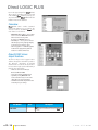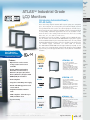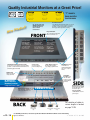
1
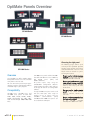
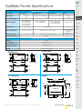
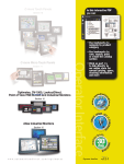
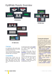
C-more Touch Panels
In this interactive PDF
you can:
Section 10
• Use bookmarks to
navigate by product
category
• Use bookmarks to
save, search, print
or e-mail the catalog
section
C-more Micro Touch Panels
Operator Interface
Section 11
• Click on part #s
to link to directly to
our online store for
current pricing, specs,
stocking information
and more
Optimates, DV-1000, LookoutDirect,
and Industrial Monitors
Section 12
Atlas Industrial Monitors
Section 12
w w w. a u to m at i o n d i re c t . c o m
Operator Interface
e12–1
OptiMate Panels Overview
OP-400 Series
OP-600 Series
Choosing the right panel
The following pages show a quick
summary of our OptiMate operator
interface panels and the key features
associated with them. Here are a few
helpful hints to consider as you’re
reviewing the features:
OP-1000 Series
Overview
Our OptiMate line offers another option
for operator interface users. The units offer
many features at a low cost.
You can connect the panels to your application by using the configuration software
and ladder logic in your program.
Compatibility
OP-400 series, OP-600 series and
OP-1000 series panels all work with
DL05, DL06, DL105, DL205, DL305,
DL405, Allen-Bradley SLC 5/03, 5/04,
5/05 and MicroLogix 1000/1200/1500
PLCs.
e12–2
Operator Interface
OP-1000 series panels and the OP-9001
also work with GE Fanuc Series 90 Micro,
GE
90/30
Series
(SNP)
and
Modbus RTU PLCs.
All panels require setup using our
OP-WINEDIT configuration software.
Simply choose the proper cable and particular type of CPU in our configuration
software.
A single OP-400 series panel can be used
with one CPU port, while single or
multiple (up to 31 panels using an
OP-9001
communications
panel)
OP-600 and OP-1000 series panels can
be used with one CPU port.
Do you need just a simple message
display? If so, look at the OP-420,
OP-440, OP-620 or OP-640.
Do you need pushbuttons or panel
lamps without message capability?
Then look at the OP-406, OP-609,
OP-613, OP-1124(-1), OP-1224
or OP-1212.
Do you need a simple setpoint
panel? If so, check out the
OP-413, OP-414, OP-613, or
OP-1312.
Do you need programmable function keys and a display? Then look
at
the
OP-420,
OP-620,
OP-640, OP-1500 or OP-1510.
1 - 80 0 - 633 - 0405
OptiMate Panels Specifications
Company
Info.
PLCs
OptiMate Panel Specifications
Specifications
OP-400 Series
OP-600 Series
Field I/O
OP-1000 Series
OP-9001
Software
Units per CPU
One per port
Service Power (Input)
1 or multiple (up to 31 with OP-9001)
5VDC
OP-406
OP-413
OP-414
OP-420
OP-440
Power Consumption
In-Rush Current
Serial Communication
Max. Cable Length
1 or multiple (up to 31 with OP-9001)
One per port
8-30VDC
0.25W @ 5VDC
0.80W @ 5VDC
0.85W @ 5VDC
0.58W @ 5VDC
0.75W @ 5VDC
8-30VDC
AC Drives
OP-1124 10W @ 8-30VDC
OP-1212 7W @ 8-30VDC
OP-1224 4W @ 8-30VDC
OP-609 2.4W @ 8-30VDC
OP-613 3 W @ 8-30VDC
3.85W @ 8-30VDC
.35-.44A for 1ms
1.5-2.0A for 2ms max.
n/a
PLC port RS-232 RJ12
PLC Port RS-232/422 15 pin D-sub (female)
One-RS-232/422 to PLC
Two-RS-422 to OP panels
(3 DB15 female)
RS-232: 50ft
RS-232: 50ft. RS-422/OP-9001: 4000ft
4000ft. shielded cable
30ft. ribbon cable
Configuration Software
Environmental Specifications
UL (file #G182843), CUL, CE
Motor
Controls
Limit
Switches
-4 to 158°F (-20 to 70°C)
Encoders
10-95% R.H. (non-condensing)
Current
Sensors
OP-600 SeriesBack
Side
Stud
0.33"
(8.3mm)
3.0"
(76.2mm)
5.40"
(137.2mm)
6.00"
(152.5mm)
Comm.
Cable
0.5"
(19mm)
1.0"
(25.4mm)
5.0 "
(127mm)
Panel Cutout
Dimensions
Stud
0.33"
(8.3mm)
3.55"
(90.2mm)
0.5"
(12.7mm)
Cable
c onnection
0.5"
(19mm)
1.15" 2.25"
(29.2mm)(57.1mm)
5.90"
(149.9mm)
3.56"
(90.4mm)
Panel
Cutout
Dimensions
Comm.
2.0"
(50.8mm)
0.75"
(19mm)
0.20"
(5mm)
Terminal
Blocks &
Wiring
0.20"
(5mm)
drill 11/64hole
Process
Relays/
Timers
0.75"
(19mm)
2.0"
(50.8mm)
Temp.
Sensors
Pushbuttons/
Lights
6.20"
(157.5mm)
6.80"
(172.7mm)
0.60"
(15.2mm)
drill 11/64 hole
Pressure
Sensors
Side
4.0"
(101.6mm)
0.60"
(15.2mm)
3.2"
(81.3mm)
Steppers/
Servos
32 to 122°F (0 to 50°C)
Power Cable
1.5"
(38.1mm)
Power
Transmiss.
Photo
Sensors
NEMA 4
OP-400 Series Back
3.5"
(88.9mm)
AC Motors
Proximity
Sensors
OP-WINEDIT
Enclosure
Agency Approval
Operating Temperature
Storage Temperature
Humidity
C-more &
other HMI
Power
OP-1000 Series
OP-9001
Back
3.55"
(88.9mm)
4.0"
(101.6mm)
8.850"
(224.8mm)
9.5"
(241.3mm)
Cable
c onn.
Stud
0.33º
(8.3mm)
0.75"
(19mm)
3.56"
(90.4mm)
1" (25.4mm)
0.85"
(21mm)
Front
drill 11/64 hole
2.0"
(50.8mm)
Appendix
Aprox.
Clearance
Req. for Cable
Connectors
3.5"
(88.9mm)
5.2"
(132mm)
J1
11.0"
(279.4mm)
J2
0.75"
(19mm)
drill 11/64hole
0.20"
(5mm)
w w w. a u to m at i o n d i re c t . c o m / o pt i m ates
Enclosures
Tools
Cable
c onnector
0.5"
(19mm)
1.55"
2.25"
(39.4mm)(57.1mm)
8.46"
(214.9mm)
Panel
Cutout
Dimensions
Circuit
Protection
Top
9.3"
(236.2mm)
Side
8.83"
(224.3mm)
Operator Interface
e12–3
Part Index
OptiMate 400/600 Series
OP-406
<--->
Indicator/pushbutton panel
• Four User-defined function keys
with LED indicators
• Six LED annunciator lamps
OP-413
• Read/write six PLC data registers
with a bank of data locations
• Four-digit numeric display
• Make setpoint adjustments by using
select button and arrows to change
values
<--->
Setpoint/display panel
• Read/write six PLC data registers
with a bank of data locations
• Eight-digit numeric display, allows
BCD double operations
• Make setpoint adjustments by using
select button and arrows to change
values
OP-420
<--->
Operator panel
• 2x20 character LCD display
• Four function keys with LEDs
• Display up to 160 pre-defined
messages which reside in the
panel’s memory
OP-440
<--->
4-line display panel
• 4x20 character LCD display with the
ability to display text, BCD double,
binary and floating-point numbers
• Display up to 160 predefined
messages which reside in the
panel’s memory
OP-PS400
<--->
Combination panel
• Nine user-defined function keys
with LED indicators
• Six LED annunciator lamps
<--->
Setpoint/display panel
OP-414
OP-609
<--->
Power Supply
OP-613
<--->
Setpoint/display panel
• Read/write 4 PLC data
registers with a bank of data
locations
• Four-digit numeric display
• Make setpoint adjustments by
using select button and arrows to
change values
• Four user-defined function keys
with LED indicators
• Two LED annunciator lamps
OP-620
<--->
Operator panel
• 2x20 character LCD display
• Five function keys with
LED indicators
• Five control keys with menu
tree capability
• Display up to 160 pre-defined
messages which reside in panel’s
memory
OP-640
<--->
4-Line display panel
• 4x20 character LCD display with
the ability to display text, BCD
double, binary and floating
point numbers
• Five function keys
• Three LED annunciator lamps
• Display up to 160 predefined
messages, which reside in
panel memory
• External 5 VDC power supply for
OP-400 series panels
• Plugs into standard 120 VAC
receptacle
Note: OP-PS400 is required for panel configuration and operation of all
OP-400 series panels. Do not power from PLC communications port.
e12–4
Operator Interface
1 - 80 0 - 633 - 0405
OptiMate 1000 Series
Company
Info.
PLCs
Field I/O
OP-1124
<--->
Software
Annunciator panel
C-more &
other HMI
• 24 high-intensity LED annunciator lamps
• Interchangeable colors (red, green, yellow)
• Create custom labels
• OP-1124-1 for <---> comes with one row each of
red, yellow and green light bars already installed
AC Drives
AC Motors
Power
Transmiss.
OP-1224
Steppers/
Servos
<--->
Motor
Controls
Pushbutton panel
• 24 individual pushbuttons with LED indicators
• Create custom labels
Proximity
Sensors
Photo
Sensors
Limit
Switches
OP-1212
Encoders
<--->
Current
Sensors
Combination panel
• 12 high-intensity LED annunciator lamps
• Interchangeable colors (red, green, yellow)
• 12 pushbuttons with LED indicators
• Create custom labels
Pressure
Sensors
Temp.
Sensors
Pushbuttons/
Lights
Process
OP-1312
<--->
Relays/
Timers
Setpoint/display panel
Comm.
• Read/Write 12 PLC data registers with 3 banks of
four data locations, each with a 4-digit display
• Create custom labels
• Three control keys for each bank of data
locations
• Make setpoint changes using the arrow
control keys
Terminal
Blocks &
Wiring
Power
Circuit
Protection
Enclosures
OP-1500/OP-1510
<--->
Tools
Operator panel
Appendix
• 2x20 character LCD display
• Full numeric keypad
• Five function keys with LED status
(OP-1510 uses 3 for menu functions)
• Three LED annunciator lamps
• Build and store up to 160 messages in the unit
• Menu capability (OP-1510)
w w w. a u to m at i o n d i re c t . c o m / o pt i m ates
Part Index
Operator Interface
e12–5
OptiMate Accessories
OP-9001
<--->
Communications master
Ribbon cable with DB15 male connectors
attached. Panels can be connected directly to the OP-9001 ports or be daisychained to other OP panels.
OP-9001
The OP-9001 is a communication master unit for connecting two
or more (up to 31) OP-600 and OP-1000 series OptiMate panels
to a single CPU communications port. It connects to any
DirectLOGIC, Allen-Bradley 5/03, 5/04, GE Series 90/30, GE
Series 90 Micro, and Modicon (Modbus RTU) CPU.
Note: The OP-9001 cannot be used with OP400 series panels.
The adjacent figure is a typical multi-drop arrangement using an
OP-9001 connected to four OptiMate Panels. The
OP-9001 is surface-mounted to the cabinet. Notice the adequate
space available to route cables and allow for proper clearance.
All the panels are configured using OP-WINEDIT software.
Power supply
(8 to 30 VDC)
OptiMate panels
Input power
connection
RS-232/422 port (to make
connections to PLC)
OP-9001
OP-WINEDIT
<--->
J1
J2
Configuration software
All of the OptiMate panels (including the OP-9001 communication master) are configured using the OptiMate OP-WINEDIT
configuration software.
Two RS-422 ports
to panels
OP-WINEDIT software is compatible with computers running
Windows 95/98/2000/NT/XP.
Simply load the software onto your personal computer. The simple
setup instructions are described in the supplied manual and in the
built-in HELP screens. The software allows setup of your complete
panel applications, including the type of PLC being used, communications protocol, type of panel (or panels) being used, and in
some cases, the format of the message text for the LCD display.
Some panels even include the ability to design a menu tree. The
setup steps are similar for all OptiMate panels. Use cable OPCCBL to connect a PC to OP-400 series panels, or
OP-ACBL-1 to connect to OP-600 or OP-1000.
Note: When using the OptiMate 600 series panels (except for the OP-640),
OP-WINEDIT software version 2.0 or later is required. When using the OptiMate
400 series panels or the OP-640, version 2.3 or later is required.
e12–6
Operator Interface
1 - 80 0 - 633 - 0405
OptiMate Cables
Company
Info.
PLCs
Cables for OptiMate Panel-to-PLC Connection
PLC Family
DirectLOGIC™
DL05
DirectLOGIC™
DL06
DirectLOGIC™
DL105
DirectLOGIC™
DL205
DirectLOGIC™
DL305
CPU (or other device)
OP-2CBL
OP-2CBL-2
Port 1
OP-2CBL
OP-2CBL-2
Port 2
OP-2CBL-1
not available***
DL105: F1-130
Only one
OP-2CBL
OP-2CBL-2
D2-230
Only one
OP-2CBL
OP-2CBL-2
Top port
OP-2CBL
OP-2CBL-2
Bottom port
OP-2CBL
OP-2CBL-2
D2-250-1
D2-260
Top port
OP-2CBL
OP-2CBL-2
Bottom port
OP-2CBL-1
not available***
D2-DCM (module)
Only one
OP-4CBL-2
not available***
D3-330
Requires DCU*
OP-4CBL-2
not available***
D3-330P
Requires DCU*
OP-4CBL-2
not available***
Top port
OP-3CBL
OP-3CBL-1
Bottom port
OP-3CBL
OP-3CBL-1
Top port
OP-2CBL
OP-2CBL-2
Bottom port
OP-4CBL-2
not available***
Top port (15-pin)
OP-4CBL-1
OP-4CBL-3
Bottom port (25-pin )
OP-4CBL-2
not available***
Top port
OP-4CBL-1
OP-4CBL-3
Bottom port
OP-4CBL-2
not available***
Phone jack
OP-2CBL
OP-2CBL-2
Top port (15-pin)
OP-4CBL-1
OP-4CBL-3
Bottom port (25-pin)
OP-4CBL-2
not available***
D4-DCM (module)
Only one
OP-4CBL-2
not available***
Slice I/O panels
Only one
OP-4CBL-1
OP-4CBL-3
IC610CPU105, 106
Requires DCU*
OP-4CBL-2
not available***
All models (311-351)
RS422 serial port
not available***
not applicable
All models
RS422
Serial port
not available***
not applicable
Relays/
Timers
ModBus
RJ45 port
OP-MCBL-1**
not applicable
Comm.
325-07, PPX:325-07
Requires DCU*
OP-4CBL-2
not available***
330-37, PPX:330-37
Requires DCU*
OP-4CBL-2
not available***
325S-07 (or 325 w/Stage Kit)
Requires DCU*
OP-4CBL-2
not available***
330S-37, PPX:330S-37
Requires DCU*
OP-4CBL-2
not available***
Only one
OP-3CBL
OP-3CBL-1
If DCU is used*
OP-4CBL-2
not available***
Circuit
Protection
Only one
OP-4CBL-1
OP-4CBL-3
Enclosures
Top port (15-pin)
OP-4CBL-1
OP-4CBL-3
Bottom port (25-pin)
OP-4CBL-2
not available***
Top port (15-pin)
OP-4CBL-1
OP-4CBL-3
Bottom port (25-pin)
OP-4CBL-2
not available***
Smart Slice™ I/O panels
Only one
OP-4CBL-1
OP-4CBL-3
5/03
5/04
Bottom port
OP-ACBL-1
OP-ACBL-3
MicroLogix 1000/1200/1500
Only one
OP-ACBL-2
OP-ACBL-4
DL06: D0-06
D2-240
D3-340
D4-450
425-CPU, PPX:425-CPU
Allen-Bradley™
SLC 500
Allen-Bradley™
Software
Port 2
335-37, PPX:335-37
TI405™/
SIMATIC®
TI405™
Field I/O
OP-2CBL-2
D4-440
TI305™/
SIMATIC®
TI305™
Cables for 400 Series
OP-2CBL
D4-430
GE® Series 1
GE® Series 90/30
GE® Fanuc™
Series 90 Micro
MODICON
Cables for 600/1000 Series
Port 1
DL05: D0-05
D3-350
DirectLOGIC™
DL405
CPU Port
430-CPU, PPX:430-CPU
435-CPU, PPX:435-CPU
* Requires RS-232 Data Communications Unit (D3-232-DCU)
** 1000 series panels only
w w w. a u to m at i o n d i re c t . c o m / o pt i m ates
C-more &
other HMI
AC Drives
AC Motors
Power
Transmiss.
Steppers/
Servos
Motor
Controls
Proximity
Sensors
Photo
Sensors
Limit
Switches
Encoders
Current
Sensors
Pressure
Sensors
Temp.
Sensors
Pushbuttons/
Lights
Process
Terminal
Blocks &
Wiring
Power
Tools
Appendix
Part Index
*** Cables for connecting to these ports must be built by the user.
Pinout diagrams are in the OptiMate panel user manual or online.
Operator Interface
e12–7
DirectView 1000
DV-1000
<--->
4-line by 16-character backlit LCD display
Overview
The DirectView DV-1000 is a small, lowcost operator interface. The DV-1000 can
be directly connected to DL05, DL06,
DL105, DL205, D3-350 or DL405 CPUs.
The DV-1000 is a "ladder logic dependent" terminal which relies entirely on PLC
ladder logic to perform its functions. The
DV-1000 does not require any configuration software. Instead, setup is performed
through special reserved memory locations inside of the CPU. These special
memory areas tell the DV-1000 which
modes to use, and more importantly,
where to get its display data. The
following functions can be performed by
the DV-1000:
View memory status: Display up to four
variable address values at a time on a
single screen.
View bit status: Display 32 bits (4 lines of
8 bits) or 64 bits (4 lines of 16 bits) at a
time on a single screen. Bit data types can
include I/O points, control relays,
timer/counter and stage bits.
Change values of memory locations: Up
to 16 different variable memory values
can be changed (32 for DL405). Just
move the cursor over the appropriate digit
and press the increment (+)/decrement
(-) keys.
Units per CPU: Only one DV-1000 per
CPU.
e12–8
Operator Interface
Specifications
Cable Required
Max. Distance
Connector
DV-1000CBL or
D4-1000CBL. See the
following page
15 feet from the CPU
Phone jack RJ12
150mA @ 5VDC max
Power Consumption (supplied by PLC
communication port)
NEMA Rating
Agency Approval
Storage Temp
Operating Temp
Humidity
None
UL, CUL, CE
-4 to 158°F (-20 to 70°C)
32 to 122°F (0 to 50°C)
5-95% (non-condensing)
STD 810C
Vibration Resistance MIL
Method 514.2
Shock Resistance
MIL STD 810C
Method 516.2
Noise Immunity
Atmosphere
Manufacturer
NEMA (ICS3-304)
Part
Number
DV-1000
Price
<--->
Display user-defined messages, even with
embedded V-memory values: Each line
may contain a maximum of four
embedded values. Messages are stored in
CPU variable memory. Therefore, the
number of messages is limited only by
available CPU variable memory.
Display system-defined error messages
and user-defined fault messages even in
list format: Scroll through errors and
messages. Error logs can even show time
and date stamps on DL06 family, D2-240,
D2-250-1, D2-260, D3-350, D4-440,
D4-450 CPUs.
No corrosive gases
Koyo Electronics
Description
Direct View 1000
Timer/Counter access unit
for Direct LOGIC PLCs
DV-1000CBL <--->
Shielded cable to connect to
Direct LOGIC PLCs,
(RS-232C)
D4-1000CBL <--->
Shielded cable to connect to
15-pin port on DL405 PLCs
(RS232C)
Is the DV-1000 right for you?
The DV-1000 is best suited for
displaying information and occasionally changing setpoint parameters. To
use the DV-1000 you should be very
comfortable with ladder logic
programming. If you’re looking for an
operator control panel, you should
consider the C-more family of panels.
They are better suited for applications
that require operator interaction as a
normal part of operation.
Which CPU is best to use with the
DV-1000?
The DL05, DL105, DL06, D2-240,
D2-250-1,
D2-260,
D3-350,
D4-440, and D4-450 have ACON
instructions that make the DV-1000
easier to work with. The DL105 and
D2-230 have only one communication
port, which can be a limitation in some
cases. The DV-1000 does not work
with D3-330 or D3-340 CPUs.
1 - 80 0 - 633 - 0405
DV-1000 Dimensions and Installation
PLCs
Installation
The DV-1000 is designed to snap into a
rectangular cutout in a control panel or
other surface panel. On each side of the
housing there is a retention clip to keep
the unit in place after installation. There
are no provisions for mounting screws, so
if your particular application is subject to
high amounts of vibration, this may be a
factor in your selection process. The
drawing gives the physical dimensions of
the DV-1000 housing.
The panel cut-out dimensions provide
necessary clearance for the body of the
unit and allow the outer housing bezel to
cover the edges of the cut-out for a
nice finished appearance. The optimum
panel thickness for using the retention
clips is 1/16”" to 1/8”.
The DV-1000 can be connected to a
DL205 or DL405 DCM, but you have to
build your own cable.
4.92"
(124.9mm)
Clip mount
Field I/O
Software
Back
2.64"
(67mm)
2.8"
(71mm)
C-more &
other HMI
AC Drives
Brightness adjustment
screw (bottom)
1.34"
(34mm)
5.12"
(130mm)
AC Motors
4.94"
(125.5mm)
Power
Transmiss.
Steppers/
Servos
Panel cut-out
Dimensions
2.65"
(67.3mm)
Motor
Controls
Proximity
Sensors
1.03"
(26mm)
Photo
Sensors
DV-1000CBL
Cabling requirements
Since the DV-1000 only works with the
DL05, DL06, DL105, DL205, D3-350
and DL405 CPUs, your cabling choices
are fairly simple.
• DV-1000CBL — connects to DL05, DL06,
DL105, DL205, D3-350 and D4-450 phone
jack.
• D4-1000CBL — connects to all DL405
CPU 15-pin ports.
Maximum cable length of 15 feet between
the DV-1000 and the PLC is recommended.
Company
Info.
Limit
Switches
6.6 ft./2m
Encoders
Current
Sensors
6-pin RJ12 connectors
on both ends
Pressure
Sensors
Temp.
Sensors
Back
Pushbuttons/
Lights
6-pin RJ12 connector
Process
Use DV-1000CBL cable for connecting to DL05,
DL06, DL105, DL205, D3-350, and D4-450.
Relays/
Timers
Comm.
C-more Micro-Graphic
The new C-more Micro-Graphic Panels
are a more enhanced small, low-cost
graphic operator interface that you may
want to consider when selecting a panel.
The C-more Micro-Graphic panels are
available in both a touch screen and nontouch version. The C-more panels will
work with all DirectLOGIC PLCs and will
also work with many different 3rd party
PLCs.
6.6 ft./2m
Terminal
Blocks &
Wiring
D4-1000CBL
Shielded cable
Power
6-pin RJ12 connector
Circuit
Protection
15-pin D-shell
connector
Enclosures
6-pin RJ12 connector
Tools
Appendix
Back
Part Index
Use D4-1000CBL cable for connecting DV-1000 to DL405,
including D4-450 middle port.
w w w . a u t o m a t i o n d i r e c t . c o m / d v 10 0 0
Operator Interface
e12–9
LookoutDirect Overview
Event-driven controls
Windows architecture
Trend Views
Objects
On-the-fly changes
Graphical animation
of process flow
Real-time alarm and
data logging
The “what
you need”
HMI
For those of you
familiar
with
human machine
interface (HMI)
products, you
might recognize
the
name
L o o k o u t ®.
Marketed
by
National Instruments, Lookout is one of
the industry’s leading HMI products. We
offer our own tailor-made version of the
Lookout program, LookoutDirect.
LookoutDirect is a feature-packed 500- I/O
version of the original package and
includes drivers for the top 10 PLC/RTU
products, plus our own DirectLOGIC driver.
LookoutDirect has an easy-to-use configuration package that requires no programming or scripting. Its object-oriented,
event-driven architecture provides an
outstanding graphical interface to your
process. Users can easily create graphical
representations of their devices and link
those objects to their PLC system for realtime data acquisition, graphical animation, alarm generation, report printing,
and network connection to your business
system.
e12–10
Operator Interface
What is object-oriented?
LookoutDirect is fundamentally objectoriented. An object is a software model of
something physical that is completely selfcontained. There are many object classes,
such as switches, trends, timers, drivers,
etc. An object is simply an individual
instance of an object class. For example, if
you use 10 timers and 20 switches, you
have selected only two different object
classes, but a total of 30 objects. Objects
have a predefined database, a set of
parameters and built-in functionality. They
encapsulate their data, parameters, and
functionality into one bundle. Once you
select the objects you need, simply
connect them together as if you were physically hardwiring a control panel.
Part Number
Price
Not a programmer?
Not a problem!
Developing
an
application
in
LookoutDirect only requires that you know
how to find the letters on your keyboard
and how to move and click your computer
mouse. Select a data point and connect it
to an object.
Debug online
Once you have installed your application
on the plant floor, you can debug and
modify
it
without
irritating
the
operators. Since the process is online,
even while you are editing, they won’t miss
important data or alarms, and you won’t
get kicked out of the control room! This
feature alone can save a lot of time and
agony.
Description
PC-LKD-DEV
PC-LKD-RTE
PC-LKD-DEVUPG
PC-LKD-RTEUPG
<--->
LookoutDirect development package
<--->
LookoutDirect runtime package
<--->
LookoutDirect development package upgrade
<--->
LookoutDirect runtime package upgrade
PC-DL-PLUS
<--->
Direct LOGIC Plus Driver Object for National Instruments Lookout Software.
Allows for connection from Lookout to the Direct LOGIC line of PLCs
1 - 80 0 - 633 - 0405
Event-Driven vs Loop-Driven
Company
Info.
PLCs
Events (active notification)
Logical value
Field I/O
Timer
Software
Switch
Protocol driver
C-more &
other HMI
Formula
Text value
Data logger
Rule 1
AC Drives
AC Motors
Rule 2
Integer value
Control-panel
Power
Transmiss.
PLC
Rule 3
Steppers/
Servos
Rule 4
Floating point value
Motor
Controls
Objects
Central database
Driver is another object
Conventional HMI software loops endlessly,
testing values that seldom change.
Proximity
Sensors
LookoutDirect is event-driven for
efficiency and performance.
Photo
Sensors
Limit
Switches
Encoders
What is event-driven?
It is very important to understand that
LookoutDirect is entirely event-driven, not
loop-driven
like
many
other
industrial automation software products.
The diagram above illustrates the big
advantage of an event-driven application. Each object is totally independent,
and remains in its current state until an
event occurs. There is no waiting for the
process to loop around to the top again
before changing state or starting another
process. However, with loop-driven software, as the loop database grows larger
and larger, the response times get slower
and slower. This wastes valuable time for
you, your computer, and your process.
This is commonly called a passive
notification system.
In LookoutDirect, everything is eventdriven – monitoring, data logging,
alarming, and supervisory control. An
event is triggered by changing a setpoint,
turning on a switch, or activating a timer.
When an event occurs, it sends a signal
throughout the object network, changing
only those objects related to that specific
event. All non-related objects remain in
their current state, using no processor
time. Also, the objects themselves may
generate a different event to start another
process, creating a chain reaction but
only affecting those objects in the chain.
This event-driven approach gives
LookoutDirect a dramatic speed advantage compared to loop-driven products.
This can be referred to as an active
notification system.
Current
Sensors
Event-driven vs.
loop-driven
Pressure
Sensors
If an event-driven program is described
as an active notification and a loopdriven program as passive notification,
you can clearly get the idea that one is
going to be more take-charge than the
other. Would you rather the information
get to you when you need it or as soon as
it’s ready, or do you want to constantly
keep asking “Is it ready, is it ready?” To
go a little further, imagine that you were
expecting information from a lot of
different sources. If you had to ask each
one of them over and over for the information, not only would you waste valuable time, but also the time of the entire
process. LookoutDirect uses event-driven
architecture to avoid all of the wasted
time
polling
or
searching
for
information. Instead, it detects the arrival
of the information.
Temp.
Sensors
Pushbuttons/
Lights
Process
Relays/
Timers
Comm.
Terminal
Blocks &
Wiring
Power
Circuit
Protection
Enclosures
Tools
Appendix
Part Index
w w w. a u to m at i o n d i re c t . c o m / l o o ko u t d i re c t
Operator Interface
e12–11
LookoutDirect Features
Communications
Data logging
Supervisory control
LookoutDirect can communicate with
various external physical devices such as
PLCs, RTUs, controllers, etc. In addition to
our DirectLOGIC PLCs and Ethernet
connections, the following drivers are
included:
• Allen-Bradley PLC5
• Allen-Bradley SLC500
• ASCII
• Delta-Tau (motion control)
• GE-Series 90
• Mitsubishi FX
• Modicon Modbus ASCII, Plus, RTU
• Omron
• OPC Client and Server
• TIWAY
• Field Point I/O
Having complete historical records of your
process is invaluable. LookoutDirect
creates and maintains your process history
automatically with a combination of
various archiving mechanisms.
• Distributed historical data logging —
allows LookoutDirect to save and retrieve
data anywhere in a network
• Spreadsheet logger — creates standard
ASCII that can be opened/edited with
most spreadsheet and database programs.
• Citadel threaded database logger —
creates a historical database that can be
retrieved by the ODBC driver.
• Event logger — creates a chronological
audit trail of “who did what and when”.
The control capabilities range from very
simple to very complex. Using object
classes and complex formulas, you can
create a wide variety of control devices.
The devices can be connected in almost
any combination to handle almost any
situation.
Networking
Trends
Browse and select networking makes
connecting multiple LookoutDirect stations
easy within a production facility or at
remote locations. Click to select and
connect to any other LookoutDirect PC in
a TCP/IP based network, online and in
real-time without shutting down your
process. With the communications capabilities of Ethernet modules, virtually any
number of users at any location can
access the network. Not only will you be
capable of sharing data across the
network with other machines, but you will
be able to link other Windows
applications (via OPC) directly to
LookoutDirect.
LookoutDirect combines historical and
real-time data in a single seamless trend
graphic called Hypertrend. You can easily
scroll or jump to any specific time along
the trend or you can use the pop-up
window to search for peaks, valleys or
specific values. The software is capable of
recalling and displaying data at a rate of
more than 25,000 values per second.
This performance provides the information
you need in real time.
Alarming
LookoutDirect provides you with an alarm
set that most other packages offer, plus
more. It triggers alarms with an event or
any combination of events you specify.
Alarms can be as simple or as complex as
needed. The alarming is so versatile that
you can group your alarms in any manner,
turn off any nuisance alarms, prioritize
them, and acknowledge alarms and
events from anywhere in the network.
Security
Simple path structure to access I/O points
on other LookoutDirect stations
Convenient tree-based
network structure
A well-designed security system prevents
unauthorized access while remaining
transparent to the user. LookoutDirect
allows you to quickly log on to respond to
any situation and keeps a permanent
record of all actions while you are logged
on.
Browse and select through
objects on multiple PCs
e12–12
Operator Interface
1 - 80 0 - 633 - 0405
LookoutDirect Features
PLC
Overview
DL05/06
PLC
LookoutDirect Features
Alarms
• Simple and complex alarm capabilities
• 10 priority levels and unlimited groups
• Unwanted/nuisance alarms filtered out
• Ability to acknowledge individually, by group, or priority
• Distributed alarming allows acknowledgement from any node on
network
• Automatic report generation of alarm history
• Audio wave (.wav) files attached to alarms
Architecture
• Unique object-oriented design makes LookoutDirect extremely easy to
learn and use and provides you with dozens of prebuilt tools.
• Event-driven engine: it is a high performance system that can handle
large projects with fast response time
• True on-line configuration: modify your application without shutting
down the process
Data
Logging
• Spreadsheet object creates standard ASCII text files in .csv format
• Simple or complex logging trigger mechanisms
• High-speed data logging with Citadel database
• Efficient data compression for minimal disk usage
• Filter signals to reduce unnecessary logging
• Event logging of setpoint adjustments and complex/custom events
Expressions/
Formulas
Graphics
Networking
• Logical (Boolean) functions
• Lookup functions
• Mathematical functions
• Statistical functions
• Text functions
• Trigonometric functions
• Date/time functions
• Ability to handle custom bitmaps and metafiles
• Extensive graphical library included
• Ability to import AutoCAD files as bitmaps or metafiles
• Complex animation in X, Y and Z axis
• Multi-state animation pumps, valves, motors and more
• Variable speed rotation
• Capable of Windows color depths and resolutions
• Browse and select networking
• View screens simultaneously on separate nodes
• Make setpoint adjustments from any node
• Acknowledge alarms from any node
• Configure specific nodes for monitoring only
• Configure peer-to-peer or client-server
DL105
PLC
Recipe
• Build recipes in Excel and import
• 255 ingredients and 1000 separate recipes per object
• Unlimited number of recipe objects; download new recipes on-line
DL205
PLC
DL305
PLC
Report
Generation
• Create reports on control panel and send to printer
• Launch third-party programs to generate complex reports
• Preconfigured alarm and event reports
Security
• 10 security levels with password protection
• Viewing security hides “sensitive” data
• Control security prevents low-level operators from adjusting setpoints
• Developer can “lock” executable to prevent unauthorized modifications
• System security “locks” and prevents access to other programs
• Action verification prompts you before making adjustments
• Event logger creates permanent audit trail
DL405
PLC
Field I/O
Software
Supervisory
Control
Telemetry
Trending
• View all object connections in a simple tree-based diagram
New
• Debug connections by using convenient right-click "follow connection"
command
Connection
Windows
and Object • Use drag-and-drop in creating objects for fast application development Connectivity
Browser
• Make connections to other LookoutDirect stations across the network in
real-time
• Neutral zone (on/off control)
• Sequencing
• Timers (elapsed, delay on, delay off, pulse, one shot, interval, time of xxx,
etc.)
• Complex functions (mathematical, Boolean, lookup, arithmetic, trigonometric, text, date/time)
• Radio with/without adjustable RTS/CTS timers
• Full duplex and half duplex
• Dial-up phone lines (Modbus RTU only)
• Leased phone lines
• Complex polling algorithms
• Multiple protocols over a single radio frequency or phone line
• Automatic data blocking
• Integrated historical/real-time data in a single trend
• Forward/backward scroll bar built in
• High-speed access to historical data on hard drive
• Cursor bar gives precise values at intersections
• Ability to “jump” to specific point in time
• Pan and zoom
C-more
HMIs
Other HMI
AC Drives
Motors
Steppers/
Servos
Motor
Controls
Proximity
Sensors
Photo
Sensors
Limit
Switches
Encoders
Current
Sensors
• 32-bit for Windows NT/98/2000/WIN ME/XP (NT, 2000 or XP Pro
recommended) (Does not support Windows Vista.)
• OPC Client/ server capability for business system connectivity
• Use the open database connectivity (ODBC) driver to retrieve data from the
Citadel database
• Use dynamic data exchange (DDE) to send/receive data to/from third-party
software
• Use spreadsheet object to create ASCII text files
Pushbuttons/
Lights
Process
Relays/
Timers
Comm.
TB’s &
Wiring
Power
Circuit
Protection
Enclosures
Appendix
Part Index
w w w. a u to m at i o n d i re c t . c o m / l o o ko u t d i re c t
Operator Interface
11–13
Direct LOGIC PLUS
Due to the popularity of our DirectLOGIC
driver object and other features included
in the LookoutDirect software package, we
are pleased to offer DirectLOGIC PLUS for
National Instruments Lookout.
Overview
DirectLOGIC PLUS enables National
Instruments Lookout users to add on the
exclusive features of LookoutDirect. The
main features included are:
• DirectLOGIC Driver Object — this enables
users to connect to DirectLOGIC PLCs via
Ethernet and serial using either
K-sequence or DirectNet protocol.
• Meter Object — an easy-to-use and scalable dial gauge or bar graph type display
for monitoring any numeric signal.
• Over 300 graphics — additional graphics
install into the appropriately defined
folders in a scalable .wmf format.
DirectLOGIC driver
object features
The Driver Object is the biggest feature
and the driving force behind this product.
The Ethernet connection to ECOM
modules that is included is the best feature
because of the high speed and flexibility it
provides your application.
• Allows for connection to DL05/06
DL205 and DL405 ECOMs
• Connection to DL105 and DL305 PLCs
• Capability of using DirectSOFT and
Lookout simultaneously over the same
cable (driver versions must match)
• Link Wizard automatically identifies CPU
and configures your settings
Part Number
PC-DL-PLUS
e12–14
Price
<--->
Operator Interface
Description
Direct LOGIC PLUS Driver Object for National Instruments Lookout
Software. Allows for connection from Lookout to the Direct LOGIC
line of PLCs
1 - 80 0 - 633 - 0405
LookoutDirect System Requirements
Company
Info.
PLCs
Ordering the software
Development package — includes one
Development Environment license, one
Run-time Engine license, one key that
supports development or runtime, and all
drivers.
One of the nice things about
LookoutDirect software is that it can easily
run on industrial PCs or inexpensive, offthe-shelf PCs. The software comes on
CD-ROM so your development system PC
will need a CD-ROM drive. Run-time
systems do not require a CD-ROM drive,
but if they don’t have one they will need a
network connection to load the run-time
engine and application.
System requirements
• Windows 98/2000, XP-compatible (2000
or XP Pro recommended) (Does not
support Windows Vista.)
Minimum:
Pentium/Celeron 233 Mhz
32MB RAM
Recommended:
Pentium/Celeron 333 Mhz
64 MB RAM or greater
• 50 MB available hard drive disk space
• CD-ROM drive
• Color monitor, with at least 640x480
resolution
• USB port
Defining the
software pieces
Field I/O
Run-time package — includes one runtime engine license, one run-time key,
and all drivers.
Development environment — is used to
develop and debug the control application program (like DirectSOFT in the case
of PLCs). You can use the Development
Software on one PC to create many
different projects which can run on many
Runtime Engines.
You need to purchase one Development
Package for each PC used for application
development.
Run-time engine — is like the firmware in
the CPU of a PLC. This software will run
the application for your process.
If the PC used in your run-time application
is not your development PC, you also
need to purchase a Runtime Package for
the HMI PC.
Software
C-more &
other HMI
AC Drives
AC Motors
Power
Transmiss.
Steppers/
Servos
Motor
Controls
Proximity
Sensors
Hardware key — The hardware key must
be connected to a USB port for the software to run.
Photo
Sensors
Limit
Switches
Encoders
Part Number
PC-LKD-DEV
PC-LKD-RTE
PC-LKD-DEVUPG (See
description below)
PC-LKD-RTEUPG (See
description below)
PC-DL-PLUS
Price
Description
Current
Sensors
<--->
LookoutDirect Development package
<--->
LookoutDirect Runtime package
<--->
LookoutDirect Development package upgrade
<--->
LookoutDirect Runtime package upgrade
<--->
Direct LOGIC Plus Driver Object for National Instruments Lookout
Software. Allows for connection from Lookout to the Direct LOGIC
line of PLCs
Pressure
Sensors
Temp.
Sensors
PC-LKD-DEVUPG — LookoutDirect Version 4.5 Development Package upgrade.
Upgrade development package for any LookoutDirect 3.8.x to Version 4.51 or higher.
Includes software on CD-ROM and manual.
PC-LKD-RTEUPG — LookoutDirect Version 4.5 Runtime Package upgrade. Upgrade
runtime package for any LookoutDirect 3.8.x to Version 4.5 or higher. Includes software
on CD-ROM and manual.
Pushbuttons/
Lights
Process
Relays/
Timers
Comm.
Terminal
Blocks &
Wiring
Power
Circuit
Protection
Enclosures
Tools
Appendix
Part Index
w w w. a u to m at i o n d i re c t . c o m / l o o ko u t d i re c t
Operator Interface
e12–15
Company
Info.
PLCs
TM
ATLAS Industrial Grade
LCD Monitors
Introducing AutomationDirect’s
ATLAS family
!
t
c
u
d
ro
P
w
e
N
Field I/O
Software
TM
C-more &
other HMI
AC Drives
These new heavy duty PC monitors offer superb quality at a competitive
price. Their compact size and very thin panel mounted depth (less than
2.75”) allows them to be used in size restricted projects. And the class I,
Div 2 listing makes them ideal for installation in harsh environments found
in many factory automation applications. All sizes are available in nontouch or with a 5-wire analog resistive touchscreens. There are currently
three sizes, 15”, 17”, and 19”, in this series.
UL Approved for
Class I Division 2
Hazardous Locations
Integrated Power Supply
Features
• Optional non-touch or 5-wire
analog resistive touch screen
available
• UL 508 and UL 1604 listed for
Hazardous Locations: Class I,
Division 2, Groups A, B, C, D and
Class II, Division 2, Groups F and G
• NEMA 4/4X/12 front bezel
• RoHS compliant
• Integral 100-240 VAC power supply
• RS-232 and USB support for touch
screen models
The ATLAS series includes 15” XGA, 17” SXGA, and 19” SXGA LCD monitors. All models come standard with 100-240 VAC input power supplies
and have NEMA 4/4X/12 panel-mountable front bezels. All units provide
Analog Video (VGA) connections, and 5-wire analog resistive touchscreen
“T” models supply connection via either USB or RS-232.
The ATM1700 and ATM1900 include Digital Video Inputs (DVI) as well.
The entire series is UL/cUL listed, complies with European CE and RoHS
requirements, and is UL approved for Class I and II, Division 2 hazardous
locations.
• 2-year warranty
Power
Transmiss.
Steppers/
Servos
Motor
Controls
Proximity
Sensors
Photo
Sensors
Limit
Switches
Encoders
Current
Sensors
ATM1500
<--->
ATM1500T
(touch)
<--->
Pressure
Sensors
ATM1500 - 15"
• 15" color TFT LCD display
• XGA, 1024 x 768 native resolution
• 16 million colors
• 40,000 hrs backlight Life
• Integral 100-240 VAC power supply
• Simplified installation with no studs
• Thin design - only 2.4" behind bezel
• Accepts analog 15-pin video input
Temp.
Sensors
Pushbuttons/
Lights
Process
Relays/
Timers
Comm.
ATM1700
<--->
ATM1700T
(touch)
<--->
ATM1700 - 17"
• 17" color TFT LCD display
• SXGA, 1280 x 1024 native resolution
• 16 million colors
• 50,000 hrs backlight life
• Integral 100-240 VAC power supply
• Simplified installation with no studs
• Thin design - only 2.6" behind bezel
• (DVI) Digital Video Inputs
• Accepts analog 15-pin video input
• Simplified installation with no
studs
• VESA compliant - all modes up to
SXGA, 16 million colors
AC Motors
Terminal
Blocks &
Wiring
Power
Circuit
Protection
Enclosures
Tools
Appendix
ATM1900
<--->
ATM1900T
(touch)
<--->
w w w. a u to m at i o n d i re c t . c o m / m o n i to rs
ATM1900 - 19"
Part Index
• 19" color TFT LCD display
• SXGA, 1280 x 1024 native resolution
• 16 million colors
• 40,000 hrs backlight life
• Integral 100-240 VAC power supply
• Simplified installation with no studs
• Thin design - only 2.7" behind bezel
• (DVI) Digital Video Inputs
• Accepts analog 15-pin video input
Operator Interface
e12–17
Quality Industrial Monitors at a Great Price!
TM
15” ATLAS
17” ATLAS
19” ATLAS
<--->
ATM1500
<--->
ATM1700
<--->
ATM1900
<--->
<--->
ATM1700T
<--->
ATM1900T
ATM1500T
Bezel Construction:
0.25" Machined Aluminum with a recessed
gasket pocket to keep moisture out and
powder coated treated with an attractive
dark gray textured powder coating
UL, cUL, CE approved
NEMA 4/4X/12, IP65
FCC 47 CFR, Part 15,
Class A Bezel
Construction
!
t
c
u
d
ro
P
w
e
N
“T” models
have resistive
touchscreens
Impact Window:
.125” Lexan(Polycarbonate)
with a clear hard coat
TFT Active Matrix
with auto-scaling,
auto-adjusting
(VESA compliant - all
modes up to SXGA).
Up to 1280 x 1024
native resolution.
Simplified installation with no studs,
housed in a heavy duty steel chassis with a
powder coated machined aluminum bezel
(mounting clips included)
5 wire analog resistive touch-screen
(xxxx T part #):
Allows fine-featured
touch control; works
with gloved hands and
is durable and reliable
in industrial
environments.
Screen setup
via rear keypad
prevents tampering
ELO provided
drivers for Windows
VISTA, WinXP,
Win2000, WinNT,
Win98, Win95
and DOS.
Software works
on USB 2.0 and
serial RS-232.
“Auto-adjust” button on
back panel keypad for
easy display optimization
VESA Ready
VESA arm mount
ready (100mm)
USB Cable
Bracket keeps
the USB cable
from loosening
(included with
monitor)
The 16-gauge RoHS compliant CRS steel chassis
provides corrosion resistance and extra strength.
UL Approved for
Class I Division 2
Hazardous Locations
Integrated Power Supply
DVI
Built in Power Supply 100- 240
VAC, 50/60 Hz simplifies and
reduces installation cost .
VGA
RS-232
Ventilation located
on all sides to
reduce heat buildup 0 to 50 °C (32 to
122 °F)
USB
Compact size and very
thin panel mount depth
of less than 2.75” saves
enclosure space
Recessed cable
connections conserve
panel space
CONNECTIONS
DVI
On 17” and
19” monitors
only
VGA
RS-232
USB
Touch models Touch models
only
only
Full selection of cables in
various lengths is located
on page 12-25
For detailed specifications, refer to the Specification Charts in the ATLAS Technical section of the Catalog
e12–18
Operator Interface
1 - 80 0 - 633 - 0405
Atlas Industrial Flat Panel PC Monitors
TM
Company
Info.
PLCs
LCD Monitor Specifications
Field I/O
LCD Monitor Specifications
Software
Part Numbers
Nominal Size
Price
ATM1500
ATM1500T
ATM1700
15”
ATM1700T
ATM1900
ATM1900T
17”
<--->
<--->
<--->
C-more &
other HMI
19”
<--->
<--->
<--->
AC Drives
DISPLAY
Display Type
Display Diagonal Size
Display Size (Active Area H x W)
Native Resolution
VESA Modes Supported
Displayable Colors
Brightness, Typical
Contrast Ratio, Typical
Horizontal/Vertical View Angle,
CR>5, Typical
Backlight Life
Display Input Signal
Impact Window
AC Motors
TFT Active Matrix
14.96”
17.04”
8.98" x 11.97"
10.64" x 13.30"
18.97”
11.85" x 14.82"
XGA, 1024 x 768
Steppers/
Servos
SXGA, 1280 x 1024
Up to 1280 x 1024 @75Hz
Motor
Controls
16M
250 Nit
270 Nit
Cutout Dimensions (H x W)
Chassis Depth
Bezel Construction
Bezel Finish
Chassis Construction
Weight
Shipping Weight
600:1
800:1
160 /140
160 /160
178 /178
Photo
Sensors
40,000 hrs, Minimum
50,000 hrs, Minimum
40,000 hrs, Minimum
Limit
Switches
Analog 15-Pin D-Sub
Analog 15-Pin D-Sub, DVI-D
Encoders
0.125” Lexan (polycarbonate), clear hard coat
Current
Sensors
12.80" x 15.80" x 2.65"
14.48" x 17.14" x 2.85"
15.7" x 18.66" x 2.95"
12.00" x 15.00"
13.70" x 16.35"
14.90" x 17.75"
2.4”
2.6”
2.7”
0.25” Machined Aluminum with recessed gasket pocket
Pushbuttons/
Lights
Dark Gray Textured Powder Coated
16 Gauge RoHS Compliant CRS Steel
Process
12.5 lbs
17.5 lbs
21 lbs
15 lbs
22 lbs
26 lbs
Relays/
Timers
Comm.
100 - 240 VAC, 50/60 Hz
0.5A Maximum
20W
Terminal
Blocks &
Wiring
1A Maximum
30W
35 W
Power
ENVIRONMENTAL
Operating Temperature
Storage Temperature
Operating Humidity
Storage Humidity
Operating Shock
Operating Vibration 5-2000 Hz
Operating Altitude
Circuit
Protection
0 to 50 °C (32 to 122 °F)
-20 to 60 °C (-4 to 140 °F)
Enclosures
20% to 80% RH, noncondensing
10% to 90% RH, noncondensing
Tools
15g peak acceleration, 11msec
Appendix
0.006" peak to peak, 1g max
Part Index
Sea level - 10,000 feet
AGENCY
Front Panel NEMA Rating
FCC
EU CE Marking Compliance
Safety Agency Approvals
Pressure
Sensors
Temp.
Sensors
ELECTRICAL
AC Input Voltage
AC Input Current
Input Power
Proximity
Sensors
550:1
PHYSICAL
Overall Monitor Dimensions
(H x W x D)
Power
Transmiss.
NEMA 4/4X/12, IP65
47 CFR, Part 15, Class A
CE, EN 55022: Class A, EN 61000-3-2: Class A, EN 61000-3-3, EN 61000-6-2, IEC 60950-1
UL 508 Listed (file #E191072), UL 1604 Listed* (file #E313546), cUL Listed CSA C22.2, #142, CSA C22.2, #143*
* Class I Division 2, Groups A, B, C, D; Class II, Division 2, Groups F and G
w w w. a u to m at i o n d i re c t . c o m / m o n i to rs
Operator Interface
e12–19
Atlas Industrial Flat Panel PC Monitors
TM
LCD Monitor Specifications (cont’d)
Touch Screen Specifications
Part Numbers
ATM1500T
ATM1700T
ATM1900T
TOUCH SCREEN (Optional)
Touch Screen Technology
Interface
Resolution
5- Wire Analog Resistive
USB 1.1 and Serial RS-232
4096 x 4096
Positional Accuracy
(Maximum Error)
0.18"
0.19"
Positional Accuracy
(Standard Deviation of Error)
<0.08"
Anti-Reflective, Surface Durability - 3H
per ASTM D3363
Screen Finish
Acetone, Methylene Chloride, MEK, Isopropyl Alcohol, Hexane, Turpentine, Mineral Spirits, Unleaded
gasoline, Diesel fuel, Motor oil, Transmission fluid, Antifreeze, vinegar, ammonia-based glass cleaner.
Chemical Resistance
Per EN 61000-4-2, 1995, Withstands
20 discharges up to 15 kV
Electrostatic Protection
Expected Life
>35,000,000 Activations
Supported PC Video Modes
Video Modes
Mode
Dot Clock
(MHz)
Horizontal Freq
(KHZ)
Vertical Freq
(Hz)
H Sync
Polarity
V Sync
Polarity
640 x 350 @ 70Hz
25.144
31.430
640 x 400 @ 70Hz
28.287
31.430
70.000
P
N
70.000
N
P
720 x 400 @ 70Hz
28.287
640 x 480 @ 60Hz
25.175
31.430
70.000
N
P
31.469
59.940
N
N
640 x 480 @ 72Hz
31.500
37.861
59.940
N
N
Display Modes for
Best Image Quality
640 x 480 @ 75Hz
31.500
37.500
75.000
N
N
800 x 600 @ 56HZ
36.000
35.156
56.250
P
P
800 x 600 @ 60Hz
40.000
37.879
60.317
P
P
800 x 600 @ 72Hz
50.000
48.077
72.188
P
P
800 x 600 @ 75Hz
49.500
46.875
75.000
P
P
1024 x 768 @ 60Hz
65.000
48.363
60.005
N
N
ATM1500/ATM1500T
1024 x 768 @ 70Hz
75.000
56.476
70.070
N
P
ATM1500/ATM1500T
1024 x 768 @ 75Hz
78.750
60.023
75.030
P
P
ATM1500/ATM1500T
ATM1700/ATM1700T &
ATM1900/ATM1900T
ATM1700/ATM1700T &
ATM1900/ATM1900T
1280 x 1024 @ 60Hz
108.000
63.981
60.020
P
P
1280 x 1024 @ 75Hz
135.000
79.976
75.035
P
P
e12–20
Operator Interface
1 - 80 0 - 633 - 0405
Atlas Industrial Flat Panel PC Monitors
TM
Company
Info.
ATM1500/ATM1500T
PLCs
The Atlas ATM1500/ATM1500T is a high performance 15" color TFT flat panel monitor
specifically designed for harsh industrial environments including Class I & II, Division 2
Hazardous Locations. The ATM1500/ATM1500T accepts standard analog VGA input
and can display all VESA video modes up to 1280 x 1024 at 75Hz with 16 million colors.
An optional 5-wire analog touch screen (ATM1500T) is available that offers both RS-232
and USB interface capability. The monitor is housed in a heavy duty steel chassis with a
powder coated machined aluminum bezel. The monitor is certified to NEMA 4/4X/12
standards, is UL/CUL listed, meets CE requirements and is RoHS compliant. Panel
mounting is simplified using convenient mounting clips instead of conventional studs. All
monitors are shipped with a power input wiring receptacle, 6’ VGA cable, 6’ RS-232
cable (ATM1500T only), 2m USB Cable (ATM1500T only), mounting hardware, Quick
Installation Guide, and CD-ROM containing Hardware User’s Guide (ATM-15-USER)
and touch screen driver software for Windows 98/NT/2000/XP/Vista.
Field I/O
Software
C-more &
other HMI
AC Drives
AC Motors
Power
Transmiss.
<--->/<--->
C
Specifications
UL
R
Steppers/
Servos
Motor
Controls
US
Dimensions
Proximity
Sensors
• 15" color TFT LCD display
• UL 508 and UL 1604 listed for Hazardous
Locations: Class I, Division 2, Groups A, B, C,
D and Class II, Division 2, Groups F and G
• NEMA 4/4X/12 front bezel
• 2-year warranty
• RoHS compliant
• Integral 100-240 VAC power supply
• Simplified installation with no studs
• Thin design - only 2.4" behind bezel
• Accepts analog 15-pin video input
• VESA compliant - all modes up to SXGA,
16 million colors
• Optional 5-wire resistive touch screen with
both RS-232 and USB interface
Photo
Sensors
Limit
Switches
Encoders
Current
Sensors
Pressure
Sensors
Temp.
Sensors
Pushbuttons/
Lights
Process
Relays/
Timers
NOTE: Don’t forget the optional
cables shown in the accessories.
Comm.
Terminal
Blocks &
Wiring
Mounting Cutout
Cable Connections
Power
Circuit
Protection
WARNING
Touch Screen is still
active while display
power is off
Enclosures
DISPLAY POWER
Tools
Appendix
Part Index
CUTOUT
VIDEO CABLE
w w w. a u to m at i o n d i re c t . c o m / m o n i to rs
TOUCH SCREEN
CABLES *
* NOTE: USE ONE OR THE
OTHER, NOT BOTH.
Operator Interface
e12–21
Atlas Industrial Flat Panel PC Monitors
TM
ATM1700/ATM1700T
The Atlas ATM1700/ATM1700T is a high performance 17" color TFT flat panel monitor
specifically designed for harsh industrial environments including Class I & II, Division 2
Hazardous Locations. The ATM1700/ATM1700T accepts standard analog VGA input, or
digital DVI input, and can display all VESA video modes up to 1280 x 1024 at 75Hz with
16 million colors. An optional 5-wire analog touch screen (ATM1700T) is available that
offers both RS-232 and USB interface capability. The monitor is housed in a heavy duty
steel chassis with a powder coated machined aluminum bezel. The monitor is certified to
NEMA 4/4X/12 standards, is UL/CUL listed, meets CE requirements and is RoHS
compliant. Panel mounting is simplified using convenient mounting clips instead of
conventional studs. All monitors are shipped with a power input wiring receptacle, 6’
VGA cable, 6’ RS-232 cable (ATM1700T only), 2m USB Cable (ATM1700T only),
mounting hardware, Quick Installation Guide, and CD-ROM containing Hardware
User’s Guide (ATM-17-USER) and touch screen driver software for Windows
98/NT/2000/XP/Vista
Specifications
<--->/<--->
C
UL
R
US
Dimensions
• 17" color TFT LCD display
• UL 508 and UL 1604 listed for Hazardous
Locations: Class I, Division 2, Groups A, B, C,
D and Class II, Division 2, Groups F and G
• NEMA 4/4X/12 front bezel
• 2-year warranty
• RoHS compliant
• Integral 100-240 VAC power supply
• Simplified installation with no studs
• Thin design - only 2.6" behind bezel
• Accepts analog 15-pin video input, DVI-D
• VESA compliant - all modes up to SXGA,
16 million colors
• Optional 5-wire resistive touch screen with
both RS-232 and USB interface
NOTE: Don’t forget the optional
cables shown in the accessories.
Mounting Cutout
Cable Connections
WARNING
Touch Screen is still
active while display
power is off
DISPLAY POWER
CUTOUT
VIDEO CABLE *
e12–22
Operator Interface
TOUCH SCREEN
CABLES *
* NOTE: USE ONE OR THE
OTHER, NOT BOTH.
1 - 80 0 - 633 - 0405
Atlas Industrial Flat Panel PC Monitors
TM
Company
Info.
ATM1900/ATM1900T
PLCs
The Atlas ATM1900/ATM1900T is a high performance 19" color TFT flat panel monitor
specifically designed for harsh industrial environments including Class I & II, Division 2
Hazardous Locations. The ATM1900/ATM1900T accepts standard analog VGA input, or
digital DVI input, and can display all VESA video modes up to 1280 x 1024 at 75Hz with
16 million colors. An optional 5-wire analog touch screen (ATM1900T) is available that
offers both RS-232 and USB interface capability. The monitor is housed in a heavy duty
steel chassis with a powder coated machined aluminum bezel. The monitor is certified to
NEMA 4/4X/12 standards, is UL/CUL listed, meets CE requirements and is RoHS
compliant. Panel mounting is simplified using convenient mounting clips instead of
conventional studs. All monitors are shipped with a power input wiring receptacle, 6’
VGA cable, 6’ RS-232 cable (ATM1900T only), 2m USB Cable (ATM1900T only),
mounting hardware, Quick Installation Guide, and CD-ROM containing Hardware
User’s Guide (ATM-19-USER) and touch screen driver software for Windows
98/NT/2000/XP/Vista.
Field I/O
Specifications
Software
C-more &
other HMI
AC Drives
AC Motors
Power
Transmiss.
Steppers/
Servos
<--->/<--->
C
UL
R
Motor
Controls
US
Proximity
Sensors
Dimensions
• 19" color TFT LCD display
• UL 508 and UL 1604 listed for Hazardous
Locations: Class I, Division 2, Groups A, B, C,
D and Class II, Division 2, Groups F and G
• NEMA 4/4X/12 front bezel
• 2-year warranty
• RoHS compliant
• Integral 100-240 VAC power supply
• Simplified installation with no studs
• Thin design - only 2.7" behind bezel
• Accepts analog 15-pin video input, DVI-D
• VESA compliant - all modes up to SXGA,
16 million colors
• Optional 5-wire resistive touch screen with
both RS-232 and USB interface
Photo
Sensors
Limit
Switches
Encoders
Current
Sensors
Pressure
Sensors
Temp.
Sensors
Pushbuttons/
Lights
Process
Relays/
Timers
NOTE: Don’t forget the optional
cables shown in the accessories.
Comm.
Terminal
Blocks &
Wiring
Mounting Cutout
Cable Connections
Power
Circuit
Protection
WARNING
Touch Screen is still
active while display
power is off
Enclosures
DISPLAY POWER
Tools
Appendix
CUTOUT
Part Index
VIDEO CABLE *
w w w. a u to m at i o n d i re c t . c o m / m o n i to rs
TOUCH SCREEN
CABLES *
* NOTE: USE ONE OR THE
OTHER, NOT BOTH.
Operator Interface
e12–23
Atlas Industrial Flat Panel PC Monitors
TM
Mounting Clip Installation
Connecting Power
To install the monitor, make a cutout (according to the cutout
diagram for the respective monitor) through one of the walls of
your NEMA enclosure. Next, hold the monitor in place and install
the mounting clips. The monitor uses "U"-shaped clips and a
special gasket to achieve a proper seal. Tighten the clips to the
point where the back of the monitor's bezel just begins to contact
the front of the NEMA enclosure. The use of an adjustable torque
driver is recommended. The screws should be tightened to 8 inchpounds. Tighten the clips in a cross pattern to develop an even
pressure on the sealing gasket. DO NOT OVERTIGHTEN AS
DAMAGE CAN RESULT, CAUSING LOSS OF SEALING
INTEGRITY.
The monitor is powered from 100-240 VAC, 50/60 Hz. Power is
connected to the monitor through a removable Phoenix Contact
plug (ADC P.N. ATM-AC-CON or Phoenix Contact P.N. 1777992)
that allows for screw termination of field wiring. The use of 18
AWG or greater (12 AWG maximum wore) wire is recommended.
Connect the field wiring according to the appropriate table below.
After the connections are made, make sure the power cnoconne
screws (the two screws shown in the "Front View" below) are
securely tightened. This will prevent the plug from pulling out.
Power Wiring Diagram
Mounting Clip Diagram
TOP VIEW
ADC P.N. ATM-AC-CON or
PHOENIX CONTACT P.N. 1777992
Plug Retention Screws
FRONT VIEW
L N
PE
Power
Connection
Label
CUT AWAY
VIEW
100 VAC - 240 VAC INPUT (1.0 Amps Min)
1 2 3
PIN No.
Definition
1
AC Line Input
2
AC Neutral Return
3
Protective Earth Ground
Setting the On Screen Display (OSD) Controls
The On Screen Display (OSD) controls are used for making adjustments to the monitor's settings and are located on the back of the
monitor. They consist of a single LED and five pushbuttons (functions are described in Chapter 3 of the respective monitor’s Hardware
User’s Guide) located on the Documentation and Driver CD, or downloadable from the Online Documentation area of the
AutomationDirect Web site.
OSD Controls
OSD Main Menu Display
Power
Indicator
Display Power
Button
DISPLAY POWER
RGB
MAIN MENU
BRIGHTNESS/CONTRAST
COLOR
POSITION
SETUP
EXIT
12 8 0 X 10 24
63.9KHZ/60HZ
WARNING
Touch Screen is still
active while display
power is off
e12–24
Operator Interface
1 - 80 0 - 633 - 0405
Atlas Industrial Flat Panel PC Monitors
TM
Accessories & Replacement Parts
Part Number
Company
Info.
PLCs
USB-CBL-AB3
Description
Field I/O
Price
ft. 15-pin coaxial VGA cable. Connects any Atlas
ATM-CBL-VGA10 10
monitor to a standard VGA card.
<--->
Software
ft. 15-pin coaxial VGA cable. Connects any Atlas
ATM-CBL-VGA25 25
monitor to a standard VGA card.
<--->
C-more &
other HMI
ft. 15-pin coaxial VGA cable. Connects any Atlas
ATM-CBL-VGA50 50
monitor to a standard VGA card.
<--->
ATM-CBL-DV2M
ATM-CBL-DV3M
ATM-CBL-10
ATM-CBL-25
ATM-CBL-50
USB-CBL-AB3
USB-CBL-AB6
USB-CBL-AB10
USB-CBL-AB15
ATM-AC-CON
ATM-CLIP
6 ft. (2 meter) DVI (type D) video cable. Connects M1700
and M1900 to a standard DVI-D port. DVI cables provide
a higher bandwidth video interface than the VGA cables.
10 ft. (3 meter) DVI (type D) video cable. Connects
M1700 and M1900 to a standard DVI-D port. DVI cables
provide a higher bandwidth video interface than the VGA
cables.
10 ft. serial communication cable. Connects Atlas
monitor to std. 9-pin RS-232 port.
25 ft. serial communication cable. Connects Atlas
monitor to std. 9-pin RS-232 port.
50 ft. serial communication cable. Connects Atlas
monitor to std. 9-pin RS-232 port.
3-ft (0.9 meter) Standard USB 2.0 cable with Standard-A
plug to Standard-B plug. Suitable for all USB devices.
6-ft (1.8 meter) Standard USB 2.0 cable with Standard-A
plug to Standard-B plug. Suitable for all USB devices.
10-ft (3 meter) Standard USB 2.0 cable with Standard-A
plug to Standard-B plug. Suitable for all USB devices.
15-ft (4.6 meter) Standard USB 2.0 cable with StandardA plug to Standard-B plug. Suitable for all USB devices.
Replacement Power Wiring Connector for AC Powered
Units.
Replacement flat panel mounting clip kit. Package of 16
clips and screws.
ATM-CBL-VGA10
AC Drives
USB-CBL-AB6
<--->
AC Motors
Power
Transmiss.
<--->
Steppers/
Servos
<--->
Motor
Controls
<--->
<--->
USB-CBL-AB10
Proximity
Sensors
<--->
Photo
Sensors
<--->
Limit
Switches
<--->
<--->
<--->
Encoders
USB-CBL-AB15
Current
Sensors
<--->
Pressure
Sensors
ATM-CBL-VGA25
Temp.
Sensors
Pushbuttons/
Lights
Process
Relays/
Timers
ATM-CBL-VGA50
ATM-CBL-DV2M
ATM-AC-CON
Comm.
Terminal
Blocks &
Wiring
Power
Circuit
Protection
ATM-CBL-DV3M
ATM-CBL-10
Enclosures
Tools
ATM-CLIP
Appendix
Part Index
ATM-CBL-25
ATM-CBL-50
w w w. a u to m at i o n d i re c t . c o m / m o n i to rs
Operator Interface
e12–25