1
Reference Manual
This page intentionally left blank
10%
20%
30%
40%
50%
60%
70%
80%
90%
100%
Table Of Contents
Introduction.................................................................. 3
Welcome!......................................................................................................... 3
DEQ230 Key Features................................................................... 4
How to Use This Manual .............................................................. 5
Important Safety Instructions ................................. 7
Important Safety Instructions (English) .................................. 7
Safety symbols used in this product .......................................................... 7
Please follow these precautions when using this product: .................... 7
Instructions de Sécurité Importantes (French)...................... 9
Symboles utilisés dans ce produit............................................................... 9
Veuillez suivre ces précautions lors de l’utilisation de
l’appareil: ......................................................................................................... 9
Lesen Sie bitte die folgende Sicherheitshinweise
(German) ......................................................................................... 11
Sicherheit Symbole verwendet in diesem Produkt.................................. 11
Folgen Sie bitte diesen Vorkehrungen, wenn dieses
Produkt verwendet wird:.............................................................................. 11
CE Declaration Of Conformity ................................................... 13
FCC Compliance Statement ........................................................ 13
Chapter One: Quick Start Guide.............................. 15
If you can't wait to get started.................................................................... 15
Step 1: Hook it up to a mixer....................................................... 15
Step 2: Try some equalization..................................................... 16
Step 3: Store the Program ........................................................... 16
Chapter Two: Connections ........................................ 19
Unpacking and Inspection .......................................................... 19
Installing in a Rack....................................................................... 19
Thermal Considerations in Rack Mounting ............................ 19
AC Power Hookup ......................................................................... 20
To use the DEQ230 in another country:.................................................. 20
Connecting Inputs and Outputs................................................. 21
Connecting to the Channel or Main Inserts of a mixing
console............................................................................................................. 21
Connecting to the inserts on an instrument amplifier ........................... 23
Connecting to equipment with XLR inputs and outputs...................... 23
Connecting to equipment with S/PDIF inputs and
outputs (DEQ230D only).............................................................................. 23
About Audio Cables ...................................................................... 25
Chapter Three: Basics of Equalization .................. 27
What is equalization? ................................................................... 27
Description of the Controls......................................................... 28
Description of the Basic Modes .................................................. 29
Basic operation: Program mode................................................. 31
Basic operation: Edit mode ......................................................... 32
Basic operation: Store mode ....................................................... 38
Channel Copy................................................................................................. 39
1
Table Of Contents
Basic operation: Audition mode................................................. 40
Basic operation: Channel Level mode....................................... 42
The "Hidden" Modes ...................................................................... 43
Demonstration mode ................................................................................... 43
Real-time Analysis mode (DEQ230D only):.............................................. 43
Setup mode..................................................................................................... 44
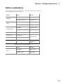
Button combinations .................................................................................... 49
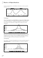
Equalization Artifacts .................................................................. 50
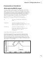
Constant Q vs. Variable Q............................................................ 51
Chapter Four: Applications ...................................... 55
Filtering effects ............................................................................. 56
Chapter Five: Program Charts................................. 59
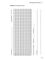
DEQ230 Settings Chart ................................................................ 69
Chapter Six: Troubleshooting .................................. 71
Restoring the Factory Programs & Defaults ........................... 71
Line Conditioners and Protectors ............................................. 71
Care and Maintenance ................................................................. 71
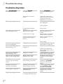
Troubleshooting Index................................................................................. 72
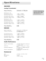
Specifications .................................................................. 75
Audio Performance....................................................................................... 75
Mechanical ...................................................................................................... 75
Warranty/Contact Alesis ............................................ 77
Alesis Limited Warranty ............................................................................... 77
Alesis Contact Information......................................................................... 78
2
Introduction
Welcome!
Thank you for purchasing the Alesis DEQ230. It is a versatile
product, and whether it becomes a part of your studio or finds
its place in your live setup, we know it will serve you well. Since
1984, we've been designing and building creative tools for the
audio community. We believe in our products, because we've
heard the results that creative people like you achieve with them.
Except as noted, when this
user guide refers to the
DEQ230 we will be
referring to both the
DEQ230 and the DEQ230D.
One of Alesis' goals is to make high-quality music technology
available to everyone. This Reference Manual is an important part
of that, because in it we try to present the DEQ230’s features in a
way that is easy to understand and remember. But even beyond
explaining each feature and parameter, this manual can be a key
that unlocks an application for the DEQ230 that you may not have
considered. So we try to write our manuals as carefully as we build
our products.
The goal of this manual is to get you the information you need as
quickly as possible, with a minimum of hassle. We hope we've
achieved that. If not, please drop us an email and give us your
suggestions on how we could improve future editions of this
manual.
We hope your investment will bring you many years of creative
enjoyment and help you achieve your goals.
Sincerely,
The people of Alesis
For more effective
service and product
update notices, please
register your DEQ230
online at:
http://www.alesis.com/
support/warranty.htm
3
Introduction
DEQ230 Key Features
1.
2.
3.
4.
5.
6.
7.
8.
9.
10.
11.
12.
13.
14.
15.
16.
17.
18.
19.
20.
21.
Offers the best of digital technology and analog-style control:
a graphic display with instant editing of any band or
combination of bands, plus the ability to store programs
60 programs total: 30 preset and 30 user-programmable
48 KHz sampling rate, 24-bit A/D/A, 28-bit internal
processing
Two channels of equalization, independent or linkable
30 EQ bands per channel, spanning 25 Hz-20 KHz in 1/3octave increments
+/- 12 dB boost/cut with center detente
Constant Q technology for finer control of audio
LOCK function for "set and forget" situations, which
prevents accidental reprogramming
AUDITION mode for automated program comparison
Individual Channel Level adjustment per program
Master Level adjustment
[LINK] button for quick creation of matched EQ curves
[BYPASS] button
Configurable editing modes to suit the way you work
Several methods of accelerated program selection
Ability to copy settings from Channel A to Channel B during
Store procedure
Easy-to-read 7-segment Numeric LED Display
Over 750 Band Gain LEDs, making it easy to read EQ curves
from a distance
SIGNAL and CLIP LEDs
Balanced input/impedance-balanced output (TRS)
Compact 1-space rackmount profile
DEQ230D only:
22. Real-time Analysis (RTA) mode for visual feedback of
incoming audio signal, with selectable metering modes
23. S/PDIF input/output, auto-senses incoming digital audio
24. Clock selectable between 44.1k and 48k sampling rates
25. MIDI in/out for program changes and sys-ex storage
26. Balanced input/output (TRS)
27. +4/-10 operating level switch (rear panel)
For full operating specifications, see page 75.
4
Introduction
How to Use This Manual
This manual is divided into the following sections describing the
various functions of and applications for the DEQ230. While it's a
good idea to read through the entire manual once carefully, those
having general knowledge about audio equipment should use the
table of contents to look up specific functions.
Chapter 1: Quick Start Guide. If you're already familiar with
equalization, this will get you started using the DEQ230 right away.
It's a short guide to the essential elements of hooking it up and
using it for the first time.
Chapter 2: Connections. This section gives detailed instructions for
connecting the DEQ230 to a variety of typical audio systems.
Helpful tips and advice are
highlighted in a shaded box
like this.
The names of specific buttons
on the DEQ230 are printed in
a bold font and bracketed:
i.e., the [BYPASS] button.
Chapter 3: Basics of Equalization. This section explains what an
equalizer does and explains the function of each of the controls.
Chapter 4: Applications. Skip to this section for tips on using the
DEQ230 in a variety of settings.
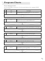
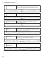
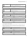
Chapter 5: Program Charts. Here you will find the names for all 60
Factory Programs, with a brief description of each and a small
graphic representation of the front panel settings.
Chapter 6: Troubleshooting. Near the end of the manual you will find
troubleshooting tips and a complete list of the DEQ230’s
specifications.
When something important
appears in the manual, an
exclamation mark (like the
one shown at left) will appear
with some explanatory text.
This symbol indicates that
this information is vital when
operating the DEQ230.
5
Introduction
This page intentionally left blank
6
Important Safety
Instructions
Important Safety Instructions (English)
Safety symbols used in this product
This symbol alerts the user that there are important
operating and maintenance instructions in the literature
accompanying this unit.
This symbol warns the user of uninsulated voltage within
the unit that can cause dangerous electric shocks.
This symbol warns the user that output connectors contain
voltages that can cause dangerous electrical shock.
Please follow these precautions when using
this product:
1.
2.
3.
4.
5.
6.
7.
8.
9.
10.
11.
Read these instructions.
Keep these instructions.
Heed all warnings.
Follow all instructions.
Do not use this apparatus near water.
Clean only with a damp cloth. Do not spray any liquid cleaner
onto the faceplate, as this may damage the front panel controls
or cause a dangerous condition.
Install in accordance with the manufacturer's instructions.
Do not install near any heat sources such as radiators, heat
registers, stoves, or other apparatus (including amplifiers) that
produce heat.
Do not defeat the safety purpose of the polarized or
grounding-type plug. A polarized plug has two blades with one
wider than the other. A grounding-type plug has two blades
and a third grounding prong. The wide blade or the third
prong are provided for your safety. When the provided plug
does not fit into your outlet, consult an electrician for
replacement of the obsolete outlet.
Protect the power cord from being walked on or pinched,
particularly at plugs, convenience receptacles, and the point
where they exit from the apparatus.
Use only attachments or accessories specified by the
manufacturer.
Continued next page
7
Important Safety Instructions
12. Use only with a cart, stand, bracket, or table designed for use
with professional audio or music equipment. In any
installation, make sure that injury or damage will not result
from cables pulling on the apparatus and its mounting. If a
cart is used, use caution when moving the cart/apparatus
combination to avoid injury from tip-over.
13. Unplug this apparatus during lightning storms or when unused
for long periods of time.
14. Refer all servicing to qualified service personnel. Servicing is
required when the apparatus has been damaged in any way,
such as when the power-supply cord or plug is damaged, liquid
has been spilled or objects have fallen into the apparatus, the
apparatus has been exposed to rain or moisture, does not
operate normally, or has been dropped.
15. This unit produces heat when operated normally. Operate in a
well-ventilated area with at least six inches of clearance from
peripheral equipment.
16. This product, in combination with an amplifier and
headphones or speakers, may be capable of producing sound
levels that could cause permanent hearing loss. Do not operate
for a long period of time at a high volume level or at a level
that is uncomfortable. If you experience any hearing loss or
ringing in the ears, you should consult an audiologist.
17. Do not expose the apparatus to dripping or splashing. Do not
place objects filled with liquids (flower vases, soft drink cans,
coffee cups) on the apparatus.
18. WARNING: To reduce the risk of fire or electric shock, do
not expose this apparatus to rain or moisture.
8
Important Safety Instructions
Instructions de Sécurité Importantes (French)
Symboles utilisés dans ce produit
Ce symbole alèrte l’utilisateur qu’il existe des instructions
de fonctionnement et de maintenance dans la documentation
jointe avec ce produit.
Ce symbole avertit l’utilisateur de la présence d’une
tension non isolée à l’intérieur de l’appareil pouvant engendrer des
chocs électriques.
Ce symbole prévient l'utilisateur de la présence de tensions
sur les raccordements de sorties, représentant un risque
d'électrocution.
Veuillez suivre ces précautions lors de
l’utilisation de l’appareil:
1.
2.
3.
4.
5.
6.
7.
8.
9.
10.
11.
Lisez ces instructions.
Gardez ces instructions.
Tenez compte de tous les avertissements.
Suivez toutes les instructions.
N’utilisez pas cet allareil à proximité de l’eau.
Ne nettoyez qu’avec un chiffon humide. Il est potentiellement
dangereux d'utiliser des pulvérisateurs ou nettoyants liquides
sur cet appareil.
Installez selon les recommandations du constructeur.
Ne pas installer à proximilé de sources de chaleur comme
radiateurs, cuisinière ou autre appareils (don’t les
amplificateurs) produisant de la chaleur.
Ne pas enlever la prise de terre du cordon secteur. Une prise
murale avec terre deux broches et une troisièrme reliée à la
terre. Cette dernière est présente pour votre sécurité. Si le
cordon secteur ne rentre pas dans la prise de courant,
demandez à un électricien qualifié de remplacer la prise.
Evitez de marcher sur le cordon secteur ou de le pincer, en
particulier au niveau de la prise, et aux endroits où il sor de
l’appareil.
N’utilisez que des accessoires spécifiés par le constructeur.
Suite de la page suivante
9
Important Safety Instructions
12. N’utilisez qu’avec un stand, ou table conçus pour l’utilisation
d’audio professionnel ou instruments de musique. Dans toute
installation, veillez de ne rien endommager à cause de câbles
qui tirent sur des appareils et leur support.
13. Débranchez l’appareil lors d’un orage ou lorsqu’il n’est pas
utilisé pendant longtemps.
14. Faites réparer par un personnel qualifié. Une réparation est
nécessaire lorsque l’appareil a été endommagé de quelque sorte
que ce soit, par exemple losrque le cordon secteur ou la prise
sont endommagés, si du liquide a coulé ou des objets se sont
introduits dans l’appareil, si celui-ci a été exposé à la pluie ou à
l’humidité, ne fonctionne pas normalement ou est tombé.
15. Puisque son fonctionement normale génère de la chaleur,
placez cet appareil au moins 15cm. des équipments
péripheriques et assurez que l’emplacement permet la
circulation de l’air.
16. Ce produit, utilisé avec un amplificateur et un casque ou des
enceintes, est capable de produite des niveaux sonores pouvant
engendrer une perte permanente de l’ouïe. Ne l’utilisez pas
pendant longtemps à un niveau sonore élevé ou à un niveau
non confortable. Si vous remarquez une perte de l’ouïe ou un
bourdonnement dans les oreilles, consultez un spécialiste.
17. N'exposez pas l'appareil à l'égoutture ou à l'éclaboussement.
Ne placez pas les objets remplis de liquides (vases à fleur,
boîtes de boisson non alcoolique, tasses de café) sur l'appareil.
18. AVERTISSEMENT: Pour réduire le risque du feu ou de
décharge électrique, n'exposez pas cet appareil à la pluie ou à
l'humidité.
10
Important Safety Instructions
Lesen Sie bitte die folgende Sicherheitshinweise (German)
Sicherheit Symbole verwendet in diesem
Produkt
Dieses Symbol alarmiert den Benutzer, daß es wichtige
Funktionieren und Wartung Anweisungen in der Literatur gibt, die
diese Maßeinheit begleitet.
Dieses Symbol warnt den Benutzer der nicht isolierten
Spannung innerhalb der Maßeinheit, die gefährliche elektrische
Schläge verursachen kann.
Dieses Symbol warnt den Benutzer, dem Ausgabestecker
Spannungen enthalten, die gefährlichen elektrischen Schlag
verursachen können.
Folgen Sie bitte diesen Vorkehrungen, wenn
dieses Produkt verwendet wird:
1.
2.
3.
4.
5.
6.
7.
8.
9.
10.
11.
Lesen Sie die Hinweise.
Halten Sie sich an die Anleitung.
Beachten Sie alle Warnungen.
Beachten Sie alle Hinweise.
Bringen Sie das Gerät nie mit Wasser in Berührung.
Verwenden Sie zur Reinigung nur ein weiches Tuch.
Verwenden Sie keine flüssigen Reinigungsmittel. Dies kann
gefährliche Folgen haben.
Halten Sie sich beim Aufbau des Gerätes an die Angaben des
Herstellers.
Stellen Sie das Gerät nich in der Nähe von Heizkörpern,
Heizungsklappen oder anderen Wärmequellen (einschließlich
Verstärkern) auf.
Verfehlen Sie nicht den Zweck des grounging Terminals auf
dem Netzstecker. Dieses Terminal wird für Ihre Sicherheit zur
Verfügung gestellt.
Verlegen Sie das Netzkabel des Gerätes niemals so, daß man
darüber stolpern kann oder daß es gequetscht wird.
Benutzen Sie nur das vom Hersteller empfohlene Zubehör.
Fortsetzung auf nächster seite
11
Important Safety Instructions
12. Verwenden Sie ausschließlich Wagen, Ständer, oder Tische, die
speziell für professionelle Audio- und Musikinstrumente
geeignet sind. Achten Sie immer darauf, daß die jeweiligen
Geräte sicher installiert sind, um Schäden und Verletzungen zu
vermeiden. Wenn Sie einen Rollwagen benutzen, achten Sie
darauf, das dieser nicht umkippt, um Verletzungen
auszuschließen.
13. Ziehen Sie während eines Gewitters oder wenn Sie das Gerät
über einen längeren Zeitraum nicht benutzen den Netzstecher
aus der Steckdose.
14. Die Wartung sollte nur durch qualifiziertes Fachpersonal
erfolgen. Die Wartung wird notwendig, wenn das Gerät
beschädigt wurde oder aber das Stromkabel oder der Stecker,
Gegenstände oder Flüssigkeit in das Gerät gelangt sind, das
Gerät dem Regen oder Feuchtigkeit ausgesetzt war und
deshalb nicht mehr normal arbeitet oder heruntergefallen ist.
15. Dieses Gerät produziert auch im normalen Betrieb Wärme.
Achten Sie deshalb auf ausreichende Lüftung mit mindestens
15 cm Abstand von anderen Geräten.
16. Dieses Produkt kann in Verbindung mit einem Verstärker und
Kopfhörern oder Lautsprechern Lautstärkepegel erzeugen, die
anhaltende Gehörschäden verursachen. Betreiben Sie es nicht
über längere Zeit mit hoher Lautstärke oder einem Pegel, der
Ihnen unangenehm is. Wenn Sie ein Nachlassen des Gehörs
oder ein Klingeln in den Ohren feststellen, sollten Sie einen
Ohrenarzt aufsuchen.
17. Setzen Sie den Apparat nicht Bratenfett oder dem Spritzen
aus. Plazieren Sie die Nachrichten, die mit Flüssigkeiten
(gefüllt werden Blumevases, Getränkdosen, Kaffeetassen)
nicht auf den Apparat.
18. WARNING: um die Gefahr des Feuers oder des elektrischen
Schlages zu verringern, setzen Sie diesen Apparat nicht Regen
oder Feuchtigkeit aus.
12
Important Safety Instructions
CE Declaration Of Conformity
See our website at:
http://www.alesis.com
FCC Compliance Statement
This device complies with Part 15 of the FCC rules. Operation is
subject to the following two conditions: (1) This device may not
cause harmful interference and (2) this device must accept any
interference received, including interference that may cause
undesired operation.
NOTE: This equipment has been tested and found to comply with
the limits for a Class B digital device, pursuant to Part 15 of the
FCC Rules. These limits are designed to provide reasonable
protection against harmful interference in a residential installation.
This equipment generates, uses and can radiate radio frequency
energy and, if not installed and used in accordance with the
instructions, may cause harmful interference to radio
communications. However, there is no guarantee that interference
will not occur in a particular installation. If this equipment does
cause harmful interference to radio or television reception, which
can be determined by turning the equipment off and on, the user
is encouraged to try to correct the interference by one or more of
the following measures:
-- Reorient or relocate the receiving antenna.
-- Increase the separation between the equipment and receiver.
-- Connect the equipment into an outlet on a circuit different from
that to which the receiver is connected.
-- Consult the dealer or an experienced radio/TV technician for
help.
13
Important Safety Instructions
This page intentionally left blank
14
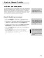
1 Quick Start Guide
If you can't wait to get started
The Alesis DEQ230 is a unique product, but its basic hookup and
operation are similar to other equalizers in most respects. If you're
experienced with signal processors, this chapter is a “shorthand”
guide for those who want to start using the DEQ230 right away. If
you have questions about any of the features, don’t worry – we’ll
cover everything in greater detail in later chapters.
If you're new to signal
processing, start with the more
detailed instructions for
hookup and operation found in
the next chapter.
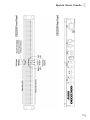
Step 1: Hook it up to a mixer
1. Plug the POWER jack on the back of the DEQ230 into a
grounded AC power source with the supplied power cable.
2. Using a pair of high-quality cables, plug the left and right main
outputs of a non-powered mixer into the CHAN A and
CHAN B INPUTs on the back of the DEQ230.
3. Connect another pair of cables to the CHAN A and CHAN
B OUTPUTs of the DEQ230 and plug them into your
amplification system or a pair of powered monitors.
4. Press the [POWER] switch on the front of the DEQ230 to
power up the unit.
5. If the LINK LED is not lit, you may want to press the
[LINK/EXIT] button on the front of the DEQ230.
That way you’ll hear the changes you make with Channel A
affect both channels of audio at once.
The DEQ230’s power will turn
on automatically once its AC
cable is plugged in, so be sure
to press the [POWER] switch
to turn the unit off while you’re
connecting it to your other
equipment.
When connecting the DEQ230
to other equipment, make sure
all gear has been turned off.
Also, to protect your speakers,
be certain your amplifier(s)
are turned all the way down
before turning your equipment
back on.
15
1
Quick Start Guide
Step 2: Try some equalization
Play some signal into the unit
While learning the unit, you should play a CD or a multitrack
source into the equalizer. Choose a song or musical passage with a
fairly consistent level, so you can take your time experimenting
with the different features.
1. Put the mixer’s main faders all the way down so you don’t
distort the unit by sending it too much signal.
2. Select program 00 on the DEQ230. The fastest way to do this
is to press the [DOWN] and [UP] buttons at the same time.
This will call up a program with all frequencies set to 0 dB,
which will allow you to hear the changes you make to the
audio more easily.
3. Begin playing your source material. Bring the mixer’s main
faders up gradually until the green LED over the word
SIGNAL begins to light up on each side. Carefully increase the
mixer’s output level until the green LEDs are lit most of the
time. If the red LEDs light up at all, back the mixer’s output
level down until they stop lighting up. This is important,
because the red LEDs indicate that the signal is clipping on
that channel.
4. Press one of the [BAND SELECT] buttons to select a
frequency. One of the LEDs above that button will begin to
blink.
5. Use the [DOWN] and [UP] buttons on either side of the
[POWER] switch to decrease or increase the chosen
frequency. If desired, select another frequency and repeat this
process.
6. Press the [BYPASS] button to hear the signal without the
equalization effect. Press it again to return to the EQ’d signal.
Remember: if one or both of the
red LEDs light up, that means
the signal is clipping. To
prevent this, reduce the level
being sent to the proper
channel.
Step 3: Store the Program
Once you have created an interesting program, you can save it to
one of the 30 User program locations. Here’s how to do this:
1. Press the [STORE] button to enter Store mode.
2. Use the [DOWN/UP] buttons to select the new location for
the edited program. For your convenience, programs 55-59
have been left “blank” so you can store your editing
experiments somewhere without fear of overwriting a
program you might want to use later.
3. Press the [STORE] button again to store the program to the
new location.
For a detailed explanation on how to use this mode, see page 38.
16
Programs 55-59 have been left
“blank” so you have
somewhere to store your
programs right away.
Quick Start Guide
1
17
1
18
Quick Start Guide
2 Connections
Unpacking and Inspection
Your DEQ230 was packed carefully at the factory. The shipping
carton was designed to protect the unit during transit. Please keep
this carton in the highly unlikely event that you need to return the
DEQ230 for servicing.
The shipping carton should contain the following items:
• DEQ230 with the same serial number as shown on shipping
carton
• A/C power supply adapter (DEQ230 only)
• A/C power cable (DEQ230D only)
• This instruction manual
Installing in a Rack
The DEQ230 may be simply set on a table, or installed in a
standard 19" audio equipment rack.
Thermal Considerations in Rack
Mounting
The DEQ230 can be mounted in an equipment rack (occupying
one rack space) or placed on a table or shelf. When you install it,
keep in mind that heat is the greatest enemy of electronic
equipment. Please observe the following:
• The DEQ230 is designed to perform properly over a range of
ambient temperatures from 10° C to +40° C (50° F to 104° F),
in up to 80% non-condensing humidity. These are not absolute
limits, but Alesis cannot guarantee that the DEQ230 will meet
its published specs or remain reliable if operated outside of
these ranges.
• Always allow adequate ventilation behind the DEQ230. Do not
seal any enclosure that holds this unit. It is not necessary to
leave an empty rack space above or below the DEQ230.
However, if your environment is unusually warm and not air
conditioned, space between units will help the units run cooler.
19
2
Connections
AC Power Hookup
The DEQ230D has what’s known as a “switching power supply.”
This means it will detect any standard line voltage from 90 to 230
volts, 50-60 Hz, and adapt itself to that. All you need is the proper
A/C cable for the country in which you find yourself. Just plug the
"female" end of the power cable into the DEQ230D’s POWER
receptacle and the “male” end into a good quality, noise-free A/C
power source.
The DEQ230 will work with any standard line voltage from 100 to
240 volts as long as the appropriate detachable power supply
adapter is used. The DEQ230 has been shipped with the suitable
adapter for the line voltage in your area.
Plug the "barrel" end of an approved power supply adapter into
the DEQ230’s POWER 9V AC jack and the transformer end into
a good quality, noise-free AC power source of the proper rating.
To use the DEQ230 in another country:
Your DEQ230 was supplied with the correct power supply adapter
for your country or local area. If you plan to travel with it to
another country, obtain an Alesis AC power supply adapter
compatible with the outlets used in the other country and use it in
place of the supplied adapter. These can be obtained through your
Alesis dealer or through the Alesis Parts department.
20
The DEQ230 is specifically
designed to be powered by
the power supply adapter we
have included. Do not
substitute any other type of
power supply adapter. If a
replacement is needed, one
may be purchased from your
Alesis dealer or from the
Alesis Parts department.
Connections
2
Connecting Inputs and Outputs
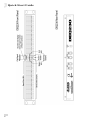
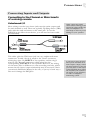
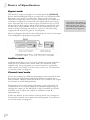
Connecting to the Channel or Main Inserts
of a mixing console
Unbalanced I/O
Most mixing consoles have insert jacks near the main outputs and
for each channel as well. These are typically Tip-Ring-Sleeve (TRS)
jacks with the send and return on the same jack. To use the
DEQ230 as an effects insert device, you will need an insert cable
(not included).
This cable splits the TRS insert jack into two unbalanced mono
connectors. Usually, the tip is wired to the "Send" connector,
which plugs into one INPUT of the equalizer, and the ring is
wired to the "Return" connector, which plugs into the
corresponding OUTPUT of the equalizer. However, the wiring
of the insert jacks is different on some recording consoles, which
means that the input/output relationship may be reversed. Check
your mixer’s Reference Manual to be sure, or just try it both ways –
this won’t damage the DEQ230.
When connecting audio
cables and/or turning power
on and off, please make sure
that your amplifiers are
turned off or down to prevent
damage to your speakers.
If your mixer does not have
insert jacks available at its
main outputs, simply connect
the main outputs of your non
powered mixer to the inputs
of the DEQ230, then connect
the outputs of the equalizer to
the inputs of your mixdown
recorder or amplified
monitoring system.
21
2
Connections
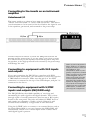
Mono connections
This example shows how to connect the DEQ230 to one mono
source. You can use this method to connect two mono sources or
one stereo source to the DEQ230. You would need two insert
cables to make both of these connections.
Stereo connections
Use two insert cables to connect the DEQ230 to the main L/R
bus in the same way you would connect it to a pair of channel
inserts. Simply connect one insert cable to the left main insert of
the mixer, and connect the two mono jacks to the CHAN A
INPUT and OUTPUT of the DEQ230. Use another insert cable
to connect the right main insert to the CHAN B INPUT and
OUTPUT of the DEQ230.
You can also simply connect the balanced main outputs of the
mixer to the inputs of the DEQ230, then connect the outputs of
the equalizer to the inputs of your mixdown recorder, monitor
system, etc.
Balanced I/O
Some recording consoles have separate balanced jacks for the
sends and returns instead of a single TRS jack. If your recording
console has these connections, use a balanced TRS cable to
connect the insert send to the INPUT of the equalizer, and
another balanced TRS cable to connect the equalizer OUTPUT to
the insert return.
Operating Levels
The DEQ230D can operate in either a +4dBu or –10dBV setting.
A rear panel switch allows you to configure the unit to your audio
environment.
The DEQ230 is a “line level” device, which means that it operates
at a nominal level of –10dBV, with a maximum input level of
+8dBV. Some equipment operates at a nominal level of +4dBu,
and can run the signal up to +24dBu. To prevent clipping, reduce
the level being sent from this equipment.
If you are unsure about the nominal operating level of the
equipment to which you will be connecting the DEQ230, refer to
the Reference Manual for that equipment.
22
Since the DEQ230 has two
channels, A and B, you can
connect two independent
sources. For example, you
could use channel A to EQ
the rhythm guitar and
channel B to EQ the bass
guitar. Or use channel A on
the kick drum and channel B
for the snare drum.
Never place the equalizer
between the power amp and
the speakers, as the highpowered levels created by
the power amp will damage
the DEQ230.
Modern production values
sometimes lead to the heavy
use of compression during
the mastering process. When
processing CD audio, you
may find it necessary at
times to lower the Channel
Level of the active program
so as to avoid clipping the
output stage of the DEQ230.
This will allow additional
headroom for more
extensive equalization. See
pg. 42 for details on the
Channel Level function.
Connections
2
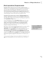
Connecting to the inserts on an instrument
amplifier
Unbalanced I/O
The insert sends on a guitar or bass amp are usually labeled
"effects send and return" or "insert send and return." This allows
your instrument to be boosted to line level before the signal is sent
to the equalizer, processed, and returned to the power amp.
Another method would be to insert the DEQ230 between the
preamp and the power amp, if you are using a two-piece system.
You should never put the equalizer between the power amp and
the speaker, as the high-powered levels created by the power amp
will damage the unit.
Connecting to equipment with XLR inputs
and outputs
If you are connecting the DEQ230 to a product with XLR
balanced inputs and outputs, you will need to convert this signal to
a TRS balanced connector. Make sure that pin 2 of the XLR
connector is connected to the tip of the TRS adapter, and pin 3 is
connected to the sleeve.
Connecting to equipment with S/PDIF
inputs and outputs (DEQ230D only)
Don't use line transformers!
Many XLR-to-1/4" adapters
sold at electronics stores are
NOT adapters, but
transformers (and very low
quality transformers at that).
Don't use these on the output
of the DEQ230—they're
unnecessary and generally
sound awful because they
don't have the headroom to
handle the DEQ230's output.
Get a hard-wired adapter or
cable from your professional
audio dealer, or make one
yourself from components.
The DEQ230D has the added capability of receiving and
transmitting its audio signal in the digital domain. This is done
through a pair of coaxial connectors (also known as RCA jacks)
found on the rear panel. The jacks are labeled S/PDIF In/Out:
each carries two channels of audio, so both Channel A and
Channel B are handled by a single cable in each direction.
Using the S/PDIF jacks to connect to an external device such as
the Alesis MasterLink is very easy, because the DEQ230D will
automatically switch over to those inputs when it senses that a
valid digital signal is present.
23
2
Connections
There are three ways to connect the DEQ230D with another
digital audio device:
Analog Signal In, Digital Signal Out
A potential use for this setup would be if you are running your
recorded tracks into a mixer that only has an analog output, but
your mixdown deck has S/PDIF inputs. Use the DEQ230D to put
that finishing touch on the mix, and then use it as a digital audio
interface into the mixdown deck. In doing this you ensure the
cleanest possible connection between the DEQ230D and the
mixdown deck.
To use the DEQ230D in this way, connect the S/PDIF Output of
the DEQ230D to the S/PDIF Input of the receiving device.
Digital Signal In, Analog Signal Out
This would be the method to use, for example, if you have a mixer
with a digital output for its main mix and an amplification system
that only has analog inputs. With this setup you would be able to
pass the audio to the DEQ230D in the digital domain, shape the
signal using its 28-bit internal processing, and then send the result
to the amplification system.
Of course, you could substitute a CD player or DAT deck for the
mixer in the above example, and/or substitute a mixdown deck or
a couple of channels on a mixer for the amplification system.
In this case, connect the S/PDIF Output of the transmitting
device to the S/PDIF Input of the DEQ230D.
Digital Signal In, Digital Signal Out
In cases where every device in your audio chain has a digital audio
input and output, the DEQ230D is right at home. Simply pass the
audio from the transmitting device’s S/PDIF Output into the
DEQ230D’s S/PDIF Input, use it to sculpt the signal, and then
pass the audio on to the next device by connecting the
DEQ230D’s S/PDIF Output to the S/PDIF Input of the
receiving device.
Operating the DEQ230D in any of the three configurations
described above is really no different from using it in a completely
analog system. For that reason, from this point on in the manual
we will make no distinction between operating the DEQ230D in
the digital or analog domains.
24
Connections
2
About Audio Cables
The connections between the DEQ230 and your studio are your
music’s lifeline, so use only high quality cables. These should be
low-capacitance shielded cables with a stranded (not solid) internal
conductor and a low-resistance shield. Although quality cables cost
more, they do make a difference.
Route cables to the DEQ230 correctly by
observing the following precautions:
• Do not bundle audio cables with AC power cords.
• Avoid running audio cables near sources of electromagnetic
interference such as transformers, monitors, computers, etc.
• Do not place cables where they can be stepped on. Stepping on
a cable may not cause immediate damage, but it can compress
the insulation between the center conductor and shield,
degrading the cable’s performance, or reduce the cable’s
reliability.
• Avoid twisting the cable or having it make sharp, right angle
turns.
• Never unplug a cable by pulling on the wire itself. Always
unplug by grasping the body of the plug firmly and pulling
directly outward.
And most importantly, keep connectors clean. Every few months,
unplug them and wipe off oxidation with a clean cloth soaked in
alcohol or contact cleaner. Insert the plugs in the jacks a few times
to clean the internal jack contacts.
Although Alesis does not endorse any specific product, chemicals
such as Tweek (also known as Stabilant) and Cramolin, when
applied to electrical connectors, are claimed to improve the
electrical contact between connectors.
25
2
Connections
This page intentionally left blank
26
3 Basics of Equalization
This section will explain how equalization works, and explain the
functions of the DEQ230’s controls.
What is equalization?
An equalizer boosts or cuts a frequency range. The DEQ230 is a
graphic equalizer, which means it has many fixed frequency bands
that can be cut or boosted. The term "graphic" is appropriate
because the combined settings of the bands often resemble a
curve, or a "graph." Thus it is often possible to know what the unit
is doing to the sound simply by looking at it from a distance. The
other type of equalizer, a parametric equalizer, can sweep the
frequency bands and adjust the frequency range affected by the cut
or boost of each band. Alesis sells a parametric equalizer called the
PEQ-450.
The most basic level of control on a graphic equalizer is the gain
setting for a band. Each of the bands represents a pre-determined
frequency range, and its gain setting controls the amount of boost
or cut for that frequency range. A setting of 0 dB means that the
signal will not be affected in the area of those audio frequencies.
Depending on the program material, boosting or cutting just one
frequency can have a significant impact on the sound. When all of
the frequency bands are taken together, the impact can be huge.
Equalization is used for:
• Adjusting the timbre of an instrument, voice, mix or effect
• Cutting or boosting frequencies to make a source easier to mix
with other tracks
• Compensating for a less-than-ideal recording
• Compensating for less-than-ideal control room or auditorium
acoustics
• Creating a filter effect
• Eliminating buzz, noise or hum
Equalizers can make your recorded tracks sound polished and
professional. Chapter 4 will describe some specific settings for
various instruments and applications.
27
3
Basics of Equalization
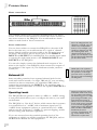
Description of the Controls
There are thirty buttons side-by-side on each channel of the
DEQ230. These are the [BAND SELECT] buttons. Above each
button is a number like "25" or "8k." These stand for the audio
frequencies, measured in Hertz (Hz), which are selected for editing
by the [BAND SELECT] buttons below them.
Situated between the [BAND SELECT] buttons for Channel A
and Channel B you will find three larger buttons. The one in the
very middle is the [POWER] button. On either side of that are
the [DOWN] and [UP] buttons, which are used to edit the gain
amount of the frequency you have selected with the [BAND
SELECT] buttons. (It is also possible to select and edit several
frequencies at once; more about this later.) The [DOWN/UP]
buttons are also used to select programs in Program mode.
Directly above these three buttons are three more buttons: the
[BYPASS], [STORE], and [LINK/EXIT] buttons. Their
functions are as follows:
[BYPASS]
When this button is first pressed, a red LED will light. This means
the DEQ230 is in Bypass mode. As long as this LED is lit,
incoming audio will pass through the unit without being affected
by the DEQ230. This is useful for comparing the "equalized"
signal with the original signal so you can decide if you like the edit
you made. Press the button again to get out of Bypass mode and
hear the effect.
[STORE]
Bypass mode “hides” the
effect the EQ and Channel
Level controls have on the
audio. However, the Master
Level function from Setup
mode is unaffected by the
[BYPASS] button. For more
information about the
relationship between Channel
Level and Master Level, see
page 45.
Once you have made an edit you would like to keep, press this
button to enter Store mode. From there you can decide which of
the 30 User locations will become the new home for the edited
Program. You can also copy the settings from Channel A to
Channel B as you store a program. For more information on this
function, see page 38.
[LINK/EXIT]
This button serves a dual purpose:
1. While in Program mode, pressing this button will cause the
settings for Channel B to "mirror" the settings for Channel A.
Any further edits you make to a band on Channel A will also
happen to that same band on Channel B. This is useful for
quickly setting up a program without having to make
independent adjustments for each channel.
2. If you’re in the middle of some other activity, such as editing
or storing, pressing this button will allow you to "exit" to
Program mode.
28
It is possible to copy the
settings from Channel A to
Channel B during the Store
process so they are not merely
“mirrored.” See page 39 for
further details.
Basics of Equalization
3
Description of the Basic Modes
Program Mode
When this manual refers to Program mode, we mean the very top
level of functionality of the DEQ230. Program mode is where you
are when it is possible to use the [DOWN/UP] buttons to select
between the different programs that reside in the unit. In this
mode, you have access to the 30 Preset programs and 30 User
programs.
A Program consists of all of the settings on the front panel, with
the exception of the status of the [BYPASS] button. The things
stored in memory and recalled when you select a program are:
•
•
•
•
The gain settings of all 30 bands for both channel A and
channel B
The status of the [LINK/EXIT] button
The gain settings for all 30 bands of channel B, even if the
Link function is active. They are merely "hidden" by the Link
function.
The individual Channel Level settings for channels A and B
If the DEQ230 has been in some other mode, pushing the
[LINK/EXIT] button will return it to Program mode. If you see
a dot to the right of the Program number LEDs, that means the
program has been edited. Be certain to save any changes you've
made that you would like to keep! To learn how to Store an edited
program, turn to page 38.
Edit mode
While in Program mode, if you push one of the [BAND
SELECT] buttons the unit will enter Edit mode. You can tell you
are in Edit mode when you see one or more of the LEDs above
the [BAND SELECT] buttons blinking. Whichever bands have a
blinking LED are the ones that will be boosted or cut when you
use the [DOWN] and [UP] buttons.
After you have edited a frequency or an Edit Group (a group of
frequencies), if you push the [LINK/EXIT] button you will be
returned to Program mode. If you made any changes, you will see
a dot to the right of the Program number LEDs. But be certain to
save any changes you've made that you would like to keep! That is
where Store mode comes in.
Pressing the [DOWN/UP]
buttons at the same time will
reset the band you have
selected to 0 dB.
Store mode
Pressing the [STORE] button takes you into Store mode. From
here you can decide which of the 30 User Programs will become
the new location for the edited program. You may also instruct the
DEQ230 to copy the settings from Channel A to Channel B
during the Store process. For information on how to perform
either of these procedures, see page 38.
29
3
Basics of Equalization
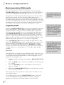
Bypass mode
This mode is nearly as simple as it sounds: push the [BYPASS]
button and the DEQ230 will let you hear the non-equalized audio.
But there’s a bit more to it than that. There are also two gain
adjustment stages that can be used to compensate for a reduction
or increase in signal level caused by the equalization curve being
used. The value for one of these stages (Channel Level) is saved
along with the EQ settings when the program is stored; the value
for the other stage (Master Level) is not. So what Bypass mode
really is doing is causing the audio to “pass by” the processing
stages that are stored as a part of the program.
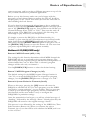
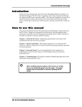
Here is a diagram that shows the relationship of each of the stages
in the DEQ230’s signal processing chain:
Audition mode
Audition mode allows you to choose specific programs and place
them into the Audition List. From there you can more easily
audition only those programs you want to hear for a particular
audio source and "jump over" the ones you do not. To learn how
to use this mode, see page 40.
Channel Level mode
If you are running two different instruments into channels A and
B, you may be experiencing drastically different signal levels in
each Channel. Channel Level mode allows you to adjust the output
of channels A and B independently.
This mode is also useful when processing a stereo signal. If the
combination of the source material and extreme EQ settings is
causing the output of the DEQ230 to clip, Channel Level mode
will allow you to adjust the output of channels A and B
simultaneously.
Unlike the Master Level function in Setup mode, the settings for
Channel Level mode are stored with each program. To learn how
to use this mode, see page 42.
30
You’ll find a description of
Channel Level mode further
down on this page. For a
description of the Master Level
function, turn to page 45.
Basics of Equalization
3
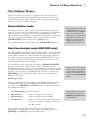
Basic operation: Program mode
Program mode is where to be if you want to call up another
program, or if you just want to know the number of the program
you are using. The DEQ230 has 60 programs in all: 30 Preset
programs and 30 User programs. The Preset programs are the
ones numbered 00-29, while the User programs are numbered 3059. You can use the Preset programs as starting points for your
own programs, but you cannot store your creations back on top of
a Preset program. That's what the User programs are for.
Navigation in Program mode is a breeze. First, if you're not in
Program mode, get there by pressing the [LINK/EXIT] button.
The large LED readout will show you the number of the current
program. All you have to do to call up a new Program is press one
of the [DOWN/UP] buttons.
If you hold down one of the [DOWN/UP] buttons for a few
seconds, the DEQ230 will begin to race through the programs.
That's one way to get from Program 10 to Program 40 more
quickly, for example. You'll also notice that it doesn't matter
whether you go up or down; you can get from Program 10 to
Program 40 going either direction.
But there's a way to get around Program mode even more quickly.
If you press and hold the [UP] button while you press the
[DOWN] button, the DEQ230 will jump to Program 00. If you
keep pressing the [DOWN] button, the DEQ230 will jump
backward through the programs in increments of 10 (50, 40, 30,
etc.). Likewise, if you press and hold the [DOWN] button while
you press the [UP] button, the DEQ230 will jump to Program 00.
And if you keep pressing the [UP] button, the DEQ230 will jump
forward through the programs in increments of 10 (10, 20, 30,
etc.).
Pressing the [DOWN/UP]
buttons at the same time
while in Program mode will
call up Program 00, the
default program.
Once you get the hang of those two methods of navigation, you
can reach any program in the unit's memory in two seconds or
less.
31
3
Basics of Equalization
Basic operation: Edit mode
If you're not already there, exit to Program mode by using the
[LINK/EXIT] button. Then select program 00 on the DEQ230
by pressing the [DOWN] and [UP] buttons at the same time.
Program 00 is a "flat" program, and it's easy to see why it's called
that: the gain setting for every band is 0 dB. Calling up this
program is almost the same as pressing the Bypass button, in that
the audio passing through the unit will not be equalized in any way.
Of course, the difference is that you can edit the program and hear
the changes that you make. If you don't already know what kind
of EQ you're looking for, this may be a good place to start.
Single Band Edit
Pressing a [BAND SELECT] button puts the DEQ230 into Edit
mode. The Numeric LED Display will change from the current
program number to the gain value in decibels (dB) of the band
you just selected. In addition, one of the Band Gain LEDs above
that [BAND SELECT] button will start blinking. If the gain
value of that band is 0 dB, the green LED will blink. This means
there is no gain change occurring in this frequency range. If it is
higher or lower than that, one of the yellow LEDs will blink. This
indicates that some amount of cut or boost is happening.
Use the [DOWN/UP] buttons to change the gain value of that
band. The [DOWN] button will lower the gain value, or "cut" the
chosen frequency; the [UP] button will raise the gain value, or
"boost" the frequency. Pressing both the [DOWN] and [UP]
buttons at the same time will reset the gain value of the frequency
to 0dB. There is an overall range of +/- 12 dB of gain change
available.
Band Solo
The DEQ230 has a handy feature called Band Solo that allows you
to “isolate” a given frequency while you are editing. This can help
you determine exactly which band you need to highlight or deemphasize. It’s simple to do:
1. Select a band by pressing and holding its [BAND SELECT]
button.
2. Press the [UP] button. You’ll se the LED for that band jump
to +12 dB.
3. Press the [DOWN] button. The LED for that band will
jump to –12 dB.
4. Release the [BAND SELECT] button and the value of that
band will be unchanged.
This only works with one band at a time, but you’ll find it to be a
very helpful feature.
To exit Edit mode, press the [LINK/EXIT] button. This will
return the DEQ230 to Program mode. The same thing will
happen if you de-select the single band you have selected.
32
Use Program 00 if you want to
start with a “clean slate” and
build a new program from the
ground up.
If the Numeric LED Display
shows “Li” when you press
[BAND SELECT] buttons o
Channel B, it means the
channels are linked. Either
make the edits on Channel A,
or return to Program mode
and press [LINK/EXIT] to
unlink the channels.
After resetting a band’s value,
you can change the level of
that band in 2 dB increments if
you hold one of the
[DOWN/UP] buttons and
press the opposite button
repeatedly. This can help you
set up a curve with greater
accuracy and speed.
Basics of Equalization
3
Band Gain Cut/Boost Ranges
Whether you are cutting or boosting a band, the first 10 dB of
change happens in 0.5 dB increments. The last 2 dB of change,
going from +/-10 dB to +/-12 dB, happens in increments of 1.0
dB. So as you make the change, the Numeric LED Display will
show you values like this: 0.5, 1.0, 1.5, 2.0, 2.5 ... 9.0, 9.5, 10, 11,
12.
It’s not possible to show a minus sign in the LED display for
negative gain values. So when you're pushing the [DOWN]
button, you'll see the same values: 0.5, 1.0, 1.5, 2.0, 2.5 ... 9.0, 9.5,
10, 11, 12. But if there's any doubt in your mind about which away
you're going, the Band Gain LED will clue you in. As soon as you
move 0.5 dB away from 0, the LED for that band will change from
green to yellow. If you are cutting the frequency, the -2 dB LED
will light. If you are boosting the frequency, the +2 dB LED will
light. And on it goes until you reach the maximum value in either
direction.
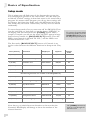
The resolution of the gain increments is higher than the number
of gain LEDs in each band on the front panel can fully display.
Therefore, you may make 0.5dB changes to gain and a band's Gain
LED may not change. The following table shows the amount of
change in dB it takes to light each of the Band Gain LEDs:
LED
Gain change
+ 12 dB
+ 12 dB
+ 10 dB
9.5 – 11 dB
+ 8 dB
7.5 - 9.0 dB
+ 6 dB
5.5 - 7.0 dB
+ 4 dB
3.5 - 5.0 dB
+ 2 dB
0.5 - 3.0 dB
0 dB
0 dB
- 2 dB
0.5 - 3.0 dB
- 4 dB
3.5 - 5.0 dB
- 6 dB
5.5 - 7.0 dB
- 8 dB
7.5 - 9.0 dB
- 10 dB
9.5 - 11 dB
- 12 dB
- 12 dB
Remember, if you want to
keep the edited program,
be sure to store it to one of
the User locations. For
instructions on how to do
this, turn to page 38.
33
3
Basics of Equalization
Multiple Band Edit
Selecting an Edit Group
Pressing a [BAND SELECT] button puts the DEQ230 into Edit
mode. And until you press one of the [DOWN/UP] buttons, you
can keep pressing [BAND SELECT] buttons until you have
several of them selected simultaneously. This is called selecting an
Edit Group. An Edit Group can be made up of any number of
bands from both channels if the Link LED is not active.
The Relative Gain Display
When you pressed the first [BAND SELECT] button, two things
happened: the Numeric LED Display changed to show the gain
value of that band, and one of the corresponding Band Gain
LEDs started to blink. Then when you pressed the second
[BAND SELECT] button, two more things happened: the
Numeric LED Display changed to show the number "0," and a
second Band Gain LED started to blink. Each additional [BAND
SELECT] button you press adds a band and a blinking LED to
the Edit Group.
But why did the Numeric LED Display change to a zero? Because,
once you have selected an Edit Group, you can cut or boost the
gain of all of the bands in the Edit Group at once. They will move
up or down in proportion to one another. The zero in the display
represents a "benchmark" for the amount of gain change that
happens to the Edit Group. The 7-segment LEDs can't display the
gain values of each band within the Edit Group all at once, so if
you raise the overall level of the Edit Group by 2 dB, that's the
number you will see. The function of the display in this case is to
tell you the Relative Gain amount.
For the sake of clarity, when this manual is describing what is
shown in the 7-segment LEDs while changing the overall gain
value of the Edit Group, we will refer to it as the Relative Gain
display.
Here’s an example: let's say you have selected the bands at 4k and
5k as your Edit Group. The initial gain value for 4k is +2 dB and
the gain value for 5k is -2 dB. The Relative Gain display at this
point will read "0." If you press the [UP] button four times, the
final value of the Relative Gain display will be a "2." The actual
gain values for 4k and 5k are now +4 dB and 0 dB, respectively,
which will be indicated by their Band Gain LEDs.
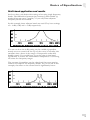
Proportional Gain Memory
It's possible you may see numbers as large as 24 in the Relative
Gain display. This is due to a very powerful aspect of the Relative
Gain feature, and it will require some careful explanation.
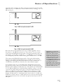
Here's another example. Let's say you have two bands selected.
The first band is set to 0 dB, and the second band is set to -12 dB.
The Relative Gain display reads "0." If you press the [UP] button
and keep holding it, you will see that number change from 0 to 12
(see fig. 1 on page 35). But it won't stop at 12; it will keep racing
34
If the Numeric LED Display
shows “Li” when you press
[BAND SELECT] buttons on
Channel B, it means the
channels are linked. Either
make the edits on Channel A,
or return to Program mode
and press [LINK/EXIT] to
unlink the channels.
In Multiple Band Edit mode,
pressing the [DOWN/UP]
buttons at the same time will
reset the Relative Gain
Display to 0. This resets the
bands within the Edit Group
back to their original values.
From this point you can
change the Relative Gain of
the Edit Group in 2 dB
increments by holding one of
the [DOWN/UP] buttons and
pressing the other one
repeatedly.
For maximum preservation of
fidelity of the input signal, the
largest number of bands in a
channel should be set to 0 dB.
For example, if you have more
than half of your bands set to
some cut amount and the
majority of those cut
frequencies are at -4 dB, then
select all bands and
compensate by +4 dB.
Basics of Equalization
3
upward until it reaches 24. This is because that's how far the band
that was set to -12 dB had to travel until it hit the "ceiling," or + 12
dB (see fig. 2).
But what about the band that was set to 0 dB originally...was it
boosted to +24 dB? The answer is, "Yes and no." It was, in the
sense that the DEQ230 keeps track of the proportional values of
the bands, even if they exceed the +/-12 dB limit of gain change
for a frequency. But the audible audio gain is limited to +/-12 dB.
The reason the DEQ230 keeps track of the gain relationship
between the bands in the Edit Group is simple. It's so you can
change your mind, pull them back down to values within the +/12 dB limit, and still have them be the same distance apart!
For example: let's say you decided these frequencies have been
boosted too much, and you cut them by 12 dB. At this point the
Relative Gain display would read "12," with band one's Gain LED
at +12 dB and band two's Gain LED at 0 dB (as in fig. 1). So far
you haven't really reduced the gain of the first band, because it's
still at +12 dB. You still want to bring it down a bit, so you take
both frequencies down another 3 dB. So now the Relative Gain
display would read "9," with band one's Gain value at +9 dB and
band two's Gain value at -3 dB. And now you can see that the gain
relationship between the two bands was preserved; they're still 12
dB apart.
Remember, pressing the
[DOWN/UP] buttons at the
same time will reset the
Relative Gain Display to 0.
From this point you can
change the Relative Gain of
the Edit Group in 2 dB
increments by holding one of
the [DOWN/UP] buttons and
pressing the other one
repeatedly. This can be a real
time-saver if you want to get
from a Relative Gain value of
+24 to a value of –24!
35
3
Basics of Equalization
One important note, though; Proportional Gain Memory is only
temporary. If you have run one or more bands "past" the +/-12
dB limit and then you exit Edit mode for any reason (such as to
store the program), the gain value of those bands will be
remembered as +/-12 dB (whichever was the value that was last
reached for those bands).
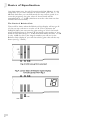
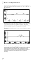
The Limits of Relative Gain
There will be times when the Relative Gain display will not go all
of the way up or down to a value of 24. This is because the
DEQ230 takes into account the gain setting of all of the bands
when an Edit Group is formed. If the highest gain setting of any
band in the Edit Group is + 6 dB, then from there down to -12 dB
is only 18 dB. So this is the largest number you will see in the
Relative Gain display if you run the relative gain value all the way
down (see fig. 3 and 4).
36
Basics of Equalization
3
Likewise, if the lowest gain setting of any band in this same Edit
Group is -4 dB, then the largest number you will see in the Relative
Gain display going all the way up is 16 (see fig. 5).
So if you run the Relative Gain display up and down repeatedly
with this Edit Group, the display will hit the "ceiling" at 16 and
bottom out at 18.
The Release Edit Group function
Once you have changed the value of the Edit Group, the DEQ230
will react one of two ways to further presses of the [BAND
SELECT] buttons. To decide which option suits your working
method or circumstance, experiment with the setting for the
Release Edit Group function in Setup Mode.
If this function is on, the very next [BAND SELECT] button
you press after you have changed the level of the Edit Group will
"release" all of the previously selected bands. The only band that
will be selected is the one you just pressed. You will know this
when it happens, because that's the only Band Gain LED that will
be blinking.
If the Release Edit Group function is off, the next [BAND
SELECT] button you press after you have changed the level of
the Edit Group will simply add that band to the Edit Group.
For a more detailed explanation of the Release Edit Group
function, see pages 44 and 45.
Remember, if you want to
keep the edited program,
be sure to store it to one of
the User locations. For
instructions on how to do
this, turn to page 38.
37
3
Basics of Equalization
Basic operation: Store mode
Once you have created a program you would like to save, press the
[STORE] button to enter Store mode. This will cause the
Numeric LED Display to blink with the number of the current
program.
If you were on a Preset program while editing, you will not be able
to store the program until you select one of the 30 User program
locations as its destination. To do this, use the [DOWN/UP]
buttons. If you press the [UP] button first, you will see the
Numeric LED Display jump to User program 30, which is the first
available User program location. If you press the [DOWN]
button first, you will see the Numeric LED Display jump to User
program 59, which is the highest-numbered User program location
available. If you were already on a User program when you entered
Store mode, then using the [DOWN/UP] buttons will call up the
next User program.
Once you are in the User program area inside Store mode, pressing
the [DOWN/UP] buttons allows you to choose a program
number between 30-59 as the destination for your edited program.
Pressing and holding one of these buttons will cause the unit to
scroll progressively faster through the available choices. If you're
holding the [DOWN] button, when the unit reaches User
program 30 it will "wrap" around to number 59 and continue
scrolling downward. Pressing and holding the [UP] button will
cause the numbers to scroll in the opposite direction, wrapping
from program 59 to program 30 and continuing upward.
As in Program mode, there's an even faster way to select the
destination program location. If you press and hold the [DOWN]
button and then push the [UP] button, the unit will jump to
Program 30. If you continue pressing the [UP] button, the
DEQ230 will jump forward through the User locations in
increments of 10 (40, 50, 30, 40, 50, etc.). Similarly, if you press
and hold the [UP] button and then push the [DOWN] button,
the unit will jump to Program 30. If you continue pressing the
[DOWN] button, the DEQ230 will jump backward through the
User locations in increments of 10 (50, 40, 30, 50, 40, 30, etc.).
Once you have chosen the location you want, press the [STORE]
button again. This will store the program into the user location
you selected.
Remember, if at any time you decide you do not want to save the
edited program, simply press the [LINK/EXIT] button to return
to Program mode. Your edited program will still be there, as
evidenced by the dot on the right side of the Numeric LED
Display. The “destination” program will not have been
overwritten.
38
Basics of Equalization
3
Channel Copy
You can use the Link function while editing to help set up identical
curves on both channels. But at some point the curves may need
to diverge slightly (or significantly). Rather than unlinking the
channels and starting all over again on Channel B, we have
included a handy feature called Channel Copy as a subset of Store
mode.
The Channel Copy feature is a real time-saver. It will allow the
settings from Channel A to be stored over whatever settings are in
Channel B, so that after the completion of the Store process there
will be no difference between the settings of Channels A and B for
that program. Then you can begin to diversify the settings of the
channels to match the needs of the incoming audio.
The process is simple, but it is subtly different from the normal
Store procedure. Pay close attention to the following steps:
1.
2.
3.
4.
5.
6.
7.
Before storing the program, unlink the channels. That way
you’ll be able to begin editing Channels A and B
independently as soon as you complete step 7.
Press and hold the [STORE] button to enter Store mode. The
Numeric LED Display will begin to flash.
While holding the [STORE] button, press the
[LINK/EXIT] button. This will cause the Link LED to
begin flashing also.
Release both buttons.
Select the location for the new program using the methods
described on the previous page.
To abort the Store procedure, press the [LINK/EXIT]
button. The settings for Channel A will not have been copied
over to Channel B.
To store the program, press the [STORE] button a second
time. The settings for Channel A will have been duplicated on
Channel B. To confirm this, toggle the [LINK/EXIT]
button. You should see no difference between the settings of
the channels. Even the Channel Level settings of Channel B
should match that of Channel A.
39
3
Basics of Equalization
Basic operation: Audition mode
No doubt there will be times when you want to switch back and
forth between different programs to determine which one is best
suited for the audio source. But as easy as it is to navigate between
the DEQ230's programs in Program mode, it's still difficult to
focus on what's happening to the audio when you're making sure
you land on the right program.
Audition mode provides the solution. It allows you to specify any
of the 60 programs within the DEQ230 as members of the
Audition List. This is like a series of bookmarks, allowing you
to jump over programs that are not intended for a particular
audio source and only call up the ones that are.
To enter Audition mode, first be sure the DEQ230 is in Program
mode. After that, press and hold the [LINK/EXIT] button and
then press the [DOWN] button. You will see four more LEDs
light up over one of the [BAND SELECT] buttons, in addition
to the Band Gain LEDs that were already lit for the current
program. These four LEDs indicate that the [BAND SELECT]
button beneath them now represents the active program in the
Audition List. You will also see the number of the active program
in the Numeric LED Display.
As you know, the DEQ230 has 60 programs. Conveniently, it also
has 60 [BAND SELECT] buttons. So in Audition mode the
[BAND SELECT] buttons represent a "map" of the Preset and
User programs, and are used to select the programs that will be
auditioned.
For example, if you entered Audition mode while you were on
Preset program 04, then the stack of lit LEDs would be above the
63 Hz band on Channel A. If you want to toggle between that
program and Preset program 10, count six [BAND SELECT]
buttons to the right and press the 250 Hz button. You will notice
that now there are four LEDs lit above the 250 Hz [BAND
SELECT] button and only two LEDs lit above the 63 Hz band.
As you recall, the four LEDs indicate which of the programs is
active. The presence of two lit LEDs indicates that a program is
part of the Audition List, but is not currently the active program.
You may add as many programs as you like to the Audition List. If
you no longer want a given program to be part of the Audition
List, simply press its [BAND SELECT] button again briefly. Its
LED will turn off, indicating that this program will be skipped
over the next time you cycle through the Audition List.
To exit Audition mode, press the [LINK/EXIT] button again, or
deselect all programs from the Audition List.
40
Be sure to store any edits you
want to keep prior to entering
Audition mode. The Audition
list only uses Preset programs
or programs that have been
stored to the User locations.
The [BYPASS] button is also
available in Audition mode.
You can use it to “audition”
the original signal manually,
or you can use program 00
“Flat” in the Audition list to
automate theDEQ230’s
return to the unprocessed
audio signal.
Remember, the very first
program is program 00. So if
you want to include program
01 in the Audition list, you will
need to select the second
[BAND SELECT] button from
the left. This is because
program 01 is the second
program in the DEQ230’s
memory.
If you can’t remember what
factory curves correspond to
each program number, refer to
the Program Charts in
Chapter 5.
Basics of Equalization
3
Audition Automation
There are two ways to toggle between the programs in the
Audition List: manually and automatically. The DEQ230 defaults
to the automatic method, which we call Audition Automation.
Once you have finished adding programs to the Audition List, the
DEQ230 begins cycling through the programs from left to right. It
will start with the currently active program, pause for several
seconds, and move on to the next. When it reaches the last
program in the Audition List, it will start over again from the first
one on the left. Remember that the stack of four LEDs will
indicate which program is currently the active one. Also note that
you can edit the Audition List by adding or removing programs
during the Audition Automation cycle.
It’s possible to shorten or lengthen the amount of time spent on
each program in the Audition List during Audition Automation.
Use the [DOWN/UP] buttons for this purpose. The time range
is from 1-25 seconds in increments of one second. You will see
the value briefly in the Numeric LED Display as you change it,
and then the display will resume showing the number of the
current program in the Audition List. The Audition Automation
time value you select will be remembered even after turning the
DEQ230 off and on again.
When changing the time
value for the Audition
Automation, keep in mind
that the choices “wrap”;
i.e., you can reach a value
of 25 from a value of 01
with a single press of the
[DOWN] button.
Audition Automation override
If you want to hear a certain program again without having to wait
for the DEQ230 to cycle through the entire Audition List, simply
press and hold that program's [BAND SELECT] button. This
will call up that program immediately. And as long as you hold
down that [BAND SELECT] button, the DEQ230 will suspend
the Audition Automation cycle and stay on that program. Once
you release the button, the next program in the Audition List will
be called up and the cycle will continue from there.
Manual Audition
If you prefer to call up each program in the Audition List at your
own pace, then you must turn off the Audition Automation
feature. To do this, you will need to enter Setup mode and toggle
the setting for the AUD AUTO function. For information on how
to do this, see page 46.
If you want to audition
programs in a specific
order, save them to
locations in the User area
(programs 30-59) in the
order you’d like to hear
them. Then select them in
Audition mode.
Once you have turned off the Audition Automation feature,
navigation through the Audition List is handled by the
[DOWN/UP] buttons. Pressing the [DOWN] button will move
you leftward through the Audition List, and pressing the [UP]
button will move you rightward through the list. If you have a lot
of programs in the Audition List, hold down one of those buttons
and after a couple of seconds the DEQ230 will begin to scroll
through them more quickly.
41
3
Basics of Equalization
Basic operation: Channel Level mode
Channel Level mode allows you to adjust the output level of
channels A and B independently or simultaneously. Use this
feature to compensate for a reduction or increase of signal level
due to the equalization curve you have selected.
To enter this mode you must start from Program mode. Once you
are there, you can enter Channel Level mode in one of two ways:
•
•
On Channel A, press and hold the 16 kHz button and then
press the 20 kHz button, or vice versa
On Channel B, press and hold the 25 Hz button and then
press the 31.5 Hz button, or vice versa. (This option only
works when the channels are not linked.)
Note: If you press only one Band Gain button, you won't
enter Channel Level mode--you may have entered Band Edit
mode by mistake.
Once you are in Channel Level
mode, you must press both of
the appropriate Band Gain
buttons on one or the other
side of the Numeric LED
Display in order to select or
deselect one of the channels. If
you press only one Band Gain
button, the channel selection
will not change.
Once the DEQ230 is in Channel Level mode, you will see the
Band Gain LEDs go completely dark except for the ones over the
buttons mentioned in the two steps above.
From this point onward, Channel Level mode operates exactly like
Band Edit mode: the settings for Release Edit Group and Edit
Time Out are in effect; if you select both channels A and B for
editing, you have selected an Edit Group; the Relative Gain
Display and Proportional Gain Memory will govern the gain
adjustments made to the Edit Group.
The only real difference between the way this mode and Edit
mode operate is in the amount of boost that is allowed to occur in
Channel Level mode. The DEQ230 will allow each channel to be
boosted up to +6 dB, with an allowable cut range of -12 dB. If
you want another 6 dB of gain (for a total of 12 dB), you will find
that in the Master Level function in Setup mode. But remember,
the settings for Channel Level mode are stored with each program.
The settings for the Master Level function are not.
To exit Channel Level mode and return to Program mode, deselect
both channels or press the [LINK/EXIT] button.
42
For information on selecting
an Edit Group, see page 34.
For information on the
Release Edit Group function,
see page 45. For information
on the Edit Time Out feature,
see page 46. For information
on the Relative Gain Display,
see page 34. For information
on Proportional Gain
Memory, see page 34.
If the Numeric LED Display
shows “Li,” when you press
[BAND SELECT] buttons on
Channel B, it means the
channels are linked. Either
make the edits on Channel A,
or return to Program mode
and press [LINK/EXIT] to
unlink the channels.
Basics of Equalization
3
The "Hidden" Modes
There are several sub-levels of operation that can be accessed
from Program mode by pressing different buttons. We covered
Channel Level mode and Audition mode on the preceding pages;
here are two more “hidden” modes:
Demonstration mode
Sometimes it’s fun to have a lot of little lights flashing from the
stage or in the studio. The DEQ230 has a special key combination
that will activate a “light show” for the entertainment of your
clients, audience, or children. To begin the pyrotechnics, first make
sure you are in Program mode. Once you are, hold down the
[LINK/EXIT] button and press the [UP] button.
To exit Demonstration mode, press the [LINK/EXIT] button.
Being in Demonstration mode
is something like being in
Audition mode; the DEQ230
will cycle automatically
through all 60 programs one
after the other. The main
difference is that while in
Demonstration mode, the
audio signal is bypassed.
Real-time Analysis mode (DEQ230D only):
The DEQ230D is capable of another “light show” that is far more
than entertaining. Real-time analysis (RTA) mode uses the Band
Gain LEDs to show you exactly which frequencies are present in
the audio signal that is passing through the DEQ230D. This is an
extremely useful tool that has been a mainstay of serious sound
reinforcement engineers for decades.
To enter RTA mode, press the two leftmost [BAND SELECT]
buttons on Channel A (25 Hz and 31 Hz). Immediately, the
DEQ230D will start giving you visual feedback as to what is going
on with the instrument or mix that is being processed. RTA mode
monitors the outputs of the DEQ230D, so when you press the
[BYPASS] button you will be seeing what you are hearing: the
unprocessed signal.
There are two ways to get out
of RTA mode: pressing the
25 Hz and 31.5Hz buttons on
Channel A simultaneously, or
by pressing the [LINK/EXIT]
button.
Metering modes
Like any professional audio product, the DEQ230D allows you to
configure the response of the Band Gain LEDs while in RTA
mode. Use the [DOWN] and [UP] buttons to select between the
four different settings:
1.
2.
3.
4.
No Peak Hold Peaks are not held.
Momentary 1
Peaks are held for one second.
Momentary 2
Peaks are held for two seconds.
Continuous
Peaks are held until the metering mode is
switched to another setting, or until you
exit RTA mode.
Held peaks may be reset at
any time by pressing the
[DOWN] and [UP] buttons
simultaneously.
If you want to reset the peaks while they are being held in
Momentary 1, Momentary 2, or Continuous settings, press the
[DOWN] and [UP] buttons at the same time.
43
3
Basics of Equalization
Setup mode
This is where you will find some of the features that govern the
way the DEQ230 operates in the other modes. They are what you
would call "Global" settings, in that their status is not stored with a
program. No matter which program you call up, these settings will
not change. And since they make such a big difference in how the
unit works, they have been "tucked away" so they won’t be altered
accidentally.
To access Setup mode, first you must turn off the DEQ230. Then
turn the unit back on, wait until you see the letters “DEQ230” in
the display, and then hold down the [STORE] button. After a
couple of seconds you will see the word "SETUP" appear in large
letters above Channel A‘s [BAND SELECT] buttons. Then the
LEDs over Channel A will read "M. LVL," and the LEDs over
Channel B will read "+00."
To return to Program mode
from Setup mode, press the
[LINK/EXIT] button or turn
the DEQ230 off and back on.
The first twelve [BAND SELECT] buttons of Channel A are
used to select between the different functions in Setup mode. They
are:
Item (button)
Function
Displayed
Options
Default
Value
1 (25 Hz)
Master Level
M. LVL
+/- 6 dB
0 dB
2 (31.5 Hz)
Release Edit Group
REL E.G.
Off/On
On
3 (40 Hz)
Audition Auto
AUD AUTO
Off/On
On
4 (50 Hz)
Edit Time Out
EDIT T.O.
Off/On
Off
5 (63 Hz)
Lock
LOCK
Off/On
Off
The following functions are available on the DEQ230D only.
6 (80 Hz)
MIDI Channel
MIDI CH
All, 1-16
ALL
7 (100 Hz)
MIDI Program Chg
PRG CHG
Off/On
On
8 (125 Hz)
Sys-Ex Transmit
SND SYX
Send?
N/A
9 (160 Hz)
Sys-Ex Receive
RCV SYX
Waiting
N/A
10 (200 Hz)
MIDI Out/Thru Select
MIDI O/T
Out/Thru
Out
11 (250 Hz)
Sample Rate Select
INT CLOCK
44.1/48
48
12 (315 Hz)
Force Analog Input
INPUT SRC
Auto/Analog
Auto
Note that as you switch from one function to the next that the
Numeric LED Display will change to show the number of the
selected function.
44
The [STORE] button may be
used to cycle through the
functions also.
Basics of Equalization
3
Here's a description of what each function does.
Button 1: Master Level (+/- 6 dB)
The Master Level function is one way to customize the DEQ230
to your environment. If the equipment in your setup tends to send
very hot signals, you can use this function to prevent the output of
the DEQ230 from clipping.
When a hot line level signal comes in, the DEQ230 has plenty of
headroom to deal with it. But if you perform some radical
equalization on this signal, it is possible that the combination of
the incoming hot signal plus the equalization you have done may
put the signal "over the top" and within range of clipping. The
Master Level function allows you to reduce the level of the
equalized signal before it reaches the final output stage of the
DEQ230.
Don't confuse this with the Channel Level settings in Edit mode.
The Channel Level settings are stored with the program, and
therefore may vary from program to program. The Master Level
setting is global; i.e., it is always active and will affect every
program. There is a diagram on page 30 that illustrates the
relationship between Channel Level and Master Level.
To lower or raise the Master Level setting, use the [DOWN/UP]
buttons. To reset the value of this function to 0 dB, press the
[DOWN] and [UP] buttons at the same time.
For an explanation of how to use the Channel Level control
feature, see page 42.
Button 2: Release Edit Group (on/off)
Of all the Setup features, this is the one that will most affect the
way you work with the DEQ230. The Release Edit Group setting
determines the behavior of the [BAND SELECT] buttons in
Edit mode.
For the sake of describing this feature, let's review some things we
already know. When you press a [BAND SELECT] button, you
enter Edit mode. If you don't press one of the [DOWN/UP]
buttons right away, you can keep pressing [BAND SELECT]
buttons until you have several of them selected simultaneously.
This is called selecting an Edit Group.
If you are likely to edit only
one or two bands at a time
when constructing a new
curve, set the Release Edit
Group function to On. This
will enable you to move
more quickly across the
audio spectrum.
Once you have selected an Edit Group, you can cut or boost the
gain of all of the bands in the Edit Group simultaneously; they
will move up or down in proportion to one another. The Release
Edit Group feature does not affect these things; this is always how
the DEQ230 operates.
However, once you make an edit, it makes a big difference whether
the Release Edit Group feature is on or off. If it is on, the very
next [BAND SELECT] button you press will "release" all of the
previously selected bands. The only band that will be selected is
the one you just pressed. You will know this when it happens,
because that's the only Band Gain LED that will be blinking.
45
3
Basics of Equalization
If the Release Edit Group feature is off, the next [BAND
SELECT] button you press after you have changed the level of
the Edit Group will simply add that band to the Edit Group. The
upside of this is the convenience of being able to edit three
frequencies +3 dB, for example, and then add another frequency
to the pile and edit them all another +2 dB without having to
reselect the first three. The downside is that you will have to
deselect all four bands if you want to grab one more frequency
and edit it by itself.
There are pros and cons to both ways of working. So, experiment
with this feature and see which way works best for you.
To enable or disable the Release Edit Group feature from this
Setup mode page, press one of the [DOWN/UP] buttons.
Button 3: Audition Automation (on/off)
This setting determines whether or not the Audition Automation
function is active. When it is, the DEQ230 will cycle automatically
through the programs in the Audition List. When it is not, the user
must cycle through the Audition List manually.
To enable or disable this function, press one of the [DOWN/UP]
buttons. For a more extensive explanation of how to use Audition
mode, turn to page 40.
Button 4: Edit Time Out (on/off)
The Edit Time Out function serves as an "auto-exit" feature.
When it is enabled, if you have not changed the gain value of any
band or Edit Group for 30 seconds, the DEQ230 will exit
automatically to Program mode.
We have included this feature so the DEQ230 can mold itself as
seamlessly as possible into your working style. If you prefer not to
have the unit continue reminding you it is still in Edit mode by
blinking its LEDs, vying for your attention, as it were, with the VU
meters on your mixer, then Edit Time Out is a feature you will
appreciate.
On the other hand, if you prefer to have the DEQ230 remain in
Edit mode so you will not lose your chosen Edit Group when the
unit returns to Program mode, you may want to turn the Edit
Time Out function off.
The default setting for this function is "Off;" to enable it press one
of the [DOWN/UP] buttons.
Button 5: Lock (on/off)
This function enables you to choose a particular program as the
only one that can be selected once the DEQ230 is powered on.
After this has been done, pressing any button besides the
[POWER] button will cause the Numeric LED Display to show
“Lo” for “locked.” This is handy for environments in which the
DEQ230 is used for tuning a room, for example, or whenever you
don't want someone calling up a different program, editing the
46
Basics of Equalization
3
current program, and/or storing a different program on top of the
one you have created for a particular application.
Before you try this feature, make sure you're happy with the
program you had selected prior to turning the unit off. It will be
the program you are "stuck" with when you turn the unit back on
after enabling the Lock feature.
If you're already in Setup mode, all you have to do to enable this
feature is press the fifth [BAND SELECT] button and then press
one of the [DOWN/UP] buttons. You should see the LEDs over
Channel B change from "OFF" to "ON." Then turn the unit off
and on again. Your DEQ230 is now locked. (No fair using this
knowledge to play tricks on your salesperson!)
It's simple to restore the DEQ230 to full functionality (i.e.,
"unlock" it). Just turn the unit off and power it up in Setup mode
again (hold down the [STORE] button and turn the unit on).
Then press the fifth [BAND SELECT] button and press one of
the [DOWN/UP] buttons to turn this feature off. The next time
you power up the DEQ230 it will operate normally.
Buttons 6-12 (DEQ230D only)
Button 6: MIDI Channel (ALL, 1-16)
The setting for this function determines which MIDI channel the
DEQ230D will use to send and receive program changes. The
ALL setting means program changes will be received regardless of
which channel they are on. When ALL is selected, program
changes will be sent only on channel 1.
Use the [DOWN/UP] buttons to select the desired setting.
Remember, the functions for
buttons 6 through 12 are only
available on the DEQ230D.
Button 7: MIDI Program Change (on/off)
The default setting for the MIDI Program Change function is
“On.” If you want the DEQ230D not to respond to program
changes, use the [DOWN/UP] buttons to change it to “Off.”
Button 8: System Exclusive Transmit (Send?)
When on this page, pressing the [UP] button will cause the
DEQ230 to transmit all 30 of its User programs over the MIDI
Out jack in “system exclusive” (sys-ex) format. This is a great way
to back up your hard-fought programs, and the combination of
this function and the next makes it easy to configure the
DEQ230D for particular settings.
Once the transmission has begun, you will see a brief message of
“Sending,” followed by the message “Done.” Shortly after that, the
DEQ230D will return to the original message “Send?”
This process is not affected by the setting of the MIDI Out/Thru
Select function (Button 10). When you instruct the unit to
Transmit, the sys-ex data will be sent whether the MIDI jack is set
to Out or Thru.
47
3
Basics of Equalization
Button 9: System Exclusive Receive (Waiting)
As long as this page is active, the DEQ230D will allow an external
device such as a computer to transmit a new bank of 30 User
programs into its User memory space. Once the external device
begins sending the proper sys-ex data, the DEQ230D will display
the message “Rcving,” or “receiving.” When the sys-ex
transmission is complete, the DEQ230D will let you know by
displaying the message “Done.”
If you change your mind in the middle of the transmission and
realize you’ve loaded in the wrong bank (or worse, you forgot to
back up the User programs first), you can interrupt the
transmission by pressing the [DOWN] button. But you’d better
act quickly, as the whole process takes only about one second.
And unfortunately, as soon the message “Rcving” is displayed the
DEQ230D begins overwriting programs in the User bank. If you
saw that message you will have lost some User programs. But if
you interrupted the transmission, you will have managed to save
some of the programs.
Button 10: MIDI Out/Thru Select (Out/Thru)
Sometimes it is necessary to “daisy-chain” MIDI devices so the
MIDI data from one unit will be passed through one or more
other pieces of MIDI gear until it is able to reach the last unit in
the chain. The DEQ230D will allow you to do that; just toggle this
function’s setting from Out to Thru.
The setting on this page will not affect whether or not the
DEQ230D will send its memory out the MIDI Out jack. When
that command is initiated (Button 8), the sys-ex data will be sent in
either case.
Button 11: Sample Rate Select (44.1/48)
The DEQ230D automatically senses an incoming digital signal
through its S/PDIF input and slaves its internal clock to that,
whether the rate is 44.1k or 48k. But if you need the DEQ230D to
serve as an A/D converter, then it also will need to be the master
clock to the receiving device.
You may prefer to record the output of the DEQ230D at either
44.1k or 48k. Use the setting of this function to set the internal
clock to the desired sample rate.
Button 12: Force Analog Input (Auto/Analog)
There may be times when you want the DEQ230D to ignore an
incoming digital signal, but you don’t want to have to reach around
to the back of the rack and unplug the cable going into the
S/PDIF input. This function will help prevent that tangled
spaghetti-mess of cables where no one knows whether the other
end is actually hooked up to anything!
Auto is the default value. To force the DEQ230D to listen only to
the balanced inputs, switch this setting from Auto to Analog.
48
Warning! Sending a
sys-ex bank into the
DEQ230D will overwrite
the User memory
locations. Make sure
you have backed up the
entire User memory
before you load in a new
set of User programs.
Basics of Equalization
3
Button combinations
Here is a list of the combinations of buttons that are possible in
the DEQ230 and what they do:
Hold:
Press:
Result
[UP] (First press)
Resets value
[UP] (2+ presses)
Jumps value
[DOWN] (First press)
Resets value
[DOWN] (2+ presses)
Jumps value
[DOWN]
Audition mode
[UP]
Demo mode
[STORE]
[LINK/EXIT]
Channel Copy
16 k (Ch. A)
20 k (Ch. A)
25 Hz (Ch. B)
31.5 Hz (Ch. B)
25 Hz (Ch. A)
31.5 Hz (Ch. A)
[DOWN]
[UP]
[LINK/EXIT]
Channel Level
RTA mode
(DEQ230D
only)
“Power up” button combinations
Press & Release
Press:
Result:
[STORE]
Setup mode
[DOWN/UP]
Reinitialize
Power
49
3
Basics of Equalization
Equalization Artifacts
When you apply a lot of EQ (6dB or more), you may hear some
consequences on the output. Here are a few common side effects
to applying a lot of equalization and some ways to avoid them.
Distortion
If you boost too many frequencies too high, you will distort the
output. If this happens, the red CLIP LED will light. To avoid
this, turn down the signal being sent to the DEQ230. Other
options include adjusting the Channel Level settings in Edit mode,
or adjusting the Master Level setting in Setup mode. The best
option is to try another method of achieving the desired effect: cut
the highs instead of boosting the low frequencies; reduce the lows
and highs instead of boosting the midrange, etc.
The potential for artifacts is
highly dependent on the audio
source material. A DEQ230
program that works well for
processing one source may
clip when processing another
source, depending on which
frequencies are present.
Making the program work may
be simply a matter of a slight
adjustment in the gain setting
for one or two bands.
Noise
If you boost the high frequencies enough you may hear noise in
your system that was inaudible otherwise. If this is objectionable,
you may want to gate that channel when it isn’t being used or
automate the console so that channel is muted when that
instrument isn’t playing.
Phasing
You may hear some phase distortion if you apply a lot of EQ,
such as boosting 12dB on several bands, for example. This is just
the nature of EQ –the more you cut or boost, the more phase
distortion will occur. Try getting the same effect with less EQ; try
cutting instead of boosting; try a different position for the
microphone. All of these suggestions can help you to achieve the
desired effect with minimal phase distortion.
50
Instruments usually sound
better when you cut the
problem frequencies instead of
boosting the frequencies you
want to feature.
Basics of Equalization
3
Constant Q vs. Variable Q
What makes the DEQ230 unique?
At their inception, graphic equalizers relied solely on a form of
equalization known as "Variable Q." The DEQ230, on the other
hand, is what is known as a "Constant Q" equalizer. This method
of equalization is a relatively recent development in the history of
sound reinforcement and recording technology. As you will see
illustrated in the charts in this section, the Constant Q method
allows for a higher degree of control over the sound being
processed because of its significantly greater accuracy.
Before we go any further, it's time for some definitions:
Q
The range of frequencies affected by a
band
Variable Q
A process in which the range of
frequencies affected by a band changes as the
amount of gain is cut/boosted
Constant Q
A process in which the range of
Frequencies affected by a band stays the
same as the amount of gain is
cut/boosted
It may help to define these terms visually as well.
In the following illustration, we see the three basic terms that
govern the operation of a single band. The vertical bar of the
graph represents decibels of cut/boost, and the horizontal bar
represents frequency in Hz. The dotted line leading to the center
of the curve indicates the frequency at which this band is set. You
can see that in this example, Q covers a range of frequencies from
about 200 Hz to about 5 KHz.
51
3
Basics of Equalization
In the next illustration, the difference between a narrow Q and a
wide Q is seen:
Variable Q
Now we're ready for a visual definition of the term Variable Q. In
the next illustration, the wider and more gradual curve represents a
lower gain setting for a variable Q equalizer. The narrower and
more steep curve represents a higher gain setting at the same
frequency:
The previous illustration has been exaggerated somewhat to make
the point, but you can see how a lower gain setting also boosts
frequencies that overlap to some extent into the regions affected
by the next highest and lowest frequency band controls.
Constant Q
In contrast, a Constant Q equalizer has a more consistent range of
frequencies under its control throughout its cut/boost range, as
illustrated below:
52
Basics of Equalization
3
Multi-band application and results
So far we have only dealt with cutting or boosting single frequency
bands. The differences between the constant Q and variable Q
methods become more "graphic," if you will, when adjacent
frequency bands are involved.
In this example, three adjacent bands are used. They have settings
of + 6 dB, 0 dB, and + 6 dB, respectively:
You can see how the 0 dB setting on the variable Q equalizer
merely serves to round off the top of the curve; in actuality, this
translates into a boost in the range of frequencies under that
band's control. You would have to cut the gain on that band
significantly to reduce the unintended consequences of boosting
the other two frequency ranges.
The constant Q equalizer, on the other hand, has more precise
control over each of the frequency bands. As you can see in this
example, the effect on the center band is significantly lower:
53
3
Basics of Equalization
To further illustrate the differences, here is a pair of examples in
which three adjacent bands have settings of + 3 dB, -3 dB, and + 3
dB, respectively:
Remember that at lower gain settings, there is an even wider Q for
a given frequency band on a variable Q equalizer. The center
frequency band needs to be edited even more drastically in order
for any noticeable reduction of frequencies in its range.
The corresponding illustration for the constant Q equalizer speaks
for itself:
We offer this information regarding the differences between
constant Q and variable Q equalizers not as an attempt to
persuade the world to reject variable Q equalizers out of hand; in
some applications either would do the job nicely. But when a
greater degree of control over the program material is needed, a
constant Q equalizer like the DEQ230 offers a significant
advantage.
54
4 Applications
This section is designed to get you started with the DEQ230 by
giving some sample settings. These are merely suggested settings;
experiment and find your own once you begin to hear what the
DEQ230 does to your sound.
In a way, it’s absurd to suggest EQ settings without knowing what
the source sounds like. EQ is a tool that’s used to change the
timbre of a sound, and it’s impossible to suggest an EQ setting
that, for example, will make all guitars sound better. So the goal of
this section is to give you some ideas for using EQ on your own
tracks.
Rock Kick Drum
A rock and roll kick drum is usually EQ’d quite a bit to make it
sound the way it does on the radio. Usually an engineer will choose
to cut some of the woofy low-midrange, while boosting the highend "slap" and maybe even some of the lows. Here is a setting to
try on a close-miked kick drum:
• Select all frequencies below 80Hz and boost 3dB
• Cut 500Hz by 8dB
• Boost all frequencies above 5kHz by 4dB
You may also want to apply some compression and gating with the
Alesis CLX-440.
Vocal Air
A popular effect on vocals is to boost the high frequencies to add
"air" to the vocal. This is an especially popular effect on ballads
sung by R&B divas. This effect is achieved by boosting the high
frequencies:
• Boost 16 kHz by 6dB
• Boost 20 kHz by 6dB
Tape Hiss Removal
If a recording has a lot of tape hiss, such as one transferred from
cassette, you can usually get rid of it by dropping the high
frequencies a bit:
• Select all frequencies from 8kHz up and cut them by 6dB
Adjust the gain of different bands to compromise between
keeping the high end of the recording and eliminating tape hiss.
55
4
Applications
Eliminating Feedback
During a live performance, you may experience feedback if a
microphone is placed too close to a monitor. However, this
feedback often occurs at one frequency before it happens at
others. You can "ring out" the monitor by using EQ to cut the
frequency that’s feeding back. The following is best to try when the
band and audience are not present:
1. Insert the EQ between the mixer’s monitor output and the
monitor amplifier.
2. Slowly and carefully raise the monitor level to the point of
feedback. Notice that it always feeds back at the same
frequency unless the mic is moved a lot. As soon as you hear
feedback, turn the monitor level down, but not off.
3. Select a band that is near where you think the feedback is
occurring. For example, if you’re getting high-frequency
feedback, try 6.3 kHz.
4. Slowly raise the 6.3 kHz Band Gain level while listening for
feedback. If you hear feedback, cut that frequency because you
guessed right.
5. If you don’t hear feedback, return that band to “0” and repeat
this procedure with another frequency band. Once you hear
feedback, cut that frequency.
This procedure can be an
effective tool in isolating and
eliminating feedback in the
main or house system as well.
If you don’t hear feedback at any frequency using this method, try
boosting the monitor level a little more.
Filtering effects
The answering machine
A popular vocal effect is to filter the voice to a limited frequency
range. This “telephone” effect is also called “futzing,” and can be
used on any instrument or mix. Here’s how to get that sound on
the DEQ230:
1. Follow the instructions for items 1 and 2 from Step 2.
2. Press all of the [BAND SELECT] buttons in the ranges
from 25 Hz to 630 Hz and from 6.3 kHz to 20 kHz on the
channel you are using.
3. Use the [DOWN] BUTTON to reduce all of these
frequencies until their LEDs are at -12 dB.
4. Select all of the unedited frequencies and boost them as high
as you can without clipping the signal.
5. Be sure to toggle the [BYPASS] button to compare the result
with the original.
56
If the Numeric LED Display
shows “Li” when you press
[BAND SELECT] buttons on
Channel B, it means the
channels are linked. Either
make the edits on Channel A, or
return to Program mode and
press [LINK/EXIT] to unlink
the channels.
Applications
4
Comb filtering
You'll understand how this effect process got its name once you
see the way it looks when recreated on the DEQ230:
1. Follow the instructions for items 1 and 2 from Step 2.
2. Starting from the far left of Channel A, press every other
[BAND SELECT] button and take those bands all the way
down to -12 dB. Then select the unedited bands and boost
them +6 dB. When you’re done, look at the LEDs on the
DEQ230 and remember the “comb” analogy. The bands set to
+6 dB are the “teeth” of the comb, and those set to –12 dB
are the spaces between the teeth.
3. For an even more interesting effect, press the [LINK/EXIT]
button to unlink the bands on Channel B from Channel A and
create the exact opposite settings. In other words, take the
“odd” bands on Channel B to +6 dB this time and the “even”
bands to –12 dB. Be sure to toggle the [BYPASS] and
[LINK/EXIT] buttons to get an idea of what is being done
to the signal as it passes through the DEQ230.
4. Experiment with different sized "teeth" and "spaces." Put two
adjacent frequencies down and the next one up, repeating the
pattern. Try "broken" teeth (i.e., boosting some frequencies
more than others)! Adjust which frequencies to emphasize/deemphasize to suit the incoming audio.
Note: depending on the
incoming audio, it may be
necessary to reduce the gain
on some bands to prevent
clipping.
There are preset programs
similar to the ones used in
these examples. You may find
it interesting to compare the
results of the different settings
used in program 08 ("Comb
filter - 125 Hz") and program
14 ("Telephone").
57
4
Applications
This page intentionally left blank
58
5 Program Charts
Note for all program charts
An "L" in the middle of the picture of the front panel indicates that a program’s LINK
function is active.
#
Title
Description
0
Flat
The DEQ230 will not affect the signal; the output signal will
sound the same as the input signal.
1
Smile
The smile curve is a time-tested technique used by live sound
engineers. No time for a sound check? Start here.
2
Brighten
If you need to give your sound a little sharpness to cut through...
3
Warmth
Soften the edginess of your mix with this program.
4
Darken
This is for the times when subtlety isn't enough.
5
Speech
This eliminates unexpected rumbling or mic handling noise and
lends some clarity to the upper end.
59
5
Program Charts
6
Loudness Plus
This curve approximates what happens when you press the
“Boost” button on some consumer-level stereo equipment. It
makes for a nicely balanced sound when listening at low levels.
7
Techno
This setting emphasizes the extremes to get the dancing bodies
really moving.
8
Comb Filter - 125 Hz
9
A: Kick
B: Snare
10
A: Bass Guitar
B: Acoustic Guitar
11
A: Male Vocal
B: Female Vocal
60
Feed a signal into it that contains 125 Hz and it will really
emphasize that frequency.
Link=Off. Feed Ch. A a kick drum for thump, beater tap, and to
reduce hollowness. Ch. B reduces low end to separate the snare
and kick and also reduces hollowness.
Link=Off. Gets you in the ballpark for bass and guitar, but your
results may vary--make adjustments as needed.
These generally fit the physics of male and female voices. The
low end is reduced to avoid unwanted rumble and the high end is
emphasized for increased intelligibility.
Program Charts
12
Cross-Over
Split a full-range mono signal into both channels; send the output
of Channel A to an amplifier feeding the woofers and send
Channel B to an amplifier feeding the tweeters.
13
Hum Reduction
Some signals have 60Hz hum no matter what you do. This
program de-emphasizes 60Hz and its harmonics without taking a
noticeable bite out of the sound.
14
Telephone
15
Less SSS
5
Use this as an effect to simulate what signals sound like passing
through the phone.
This program reduces sibilance--the sound when vocals' "S"
sounds are out of proportion to other phonetics.
Note for programs 16-20 and 22-26
Send the signal you want to equalize through Narrow Boosts 1-5 to find the frequency that
may be most objectionable. Take note of that frequency for further editing or just set the
DEQ230 to the Narrow Cut 1-5 program that matches the Boost program that emphasized
the frequency range in question.
16
Narrow Boost 1 (80Hz)
See note for programs 16-20 and 22-26
17
Narrow Boost 2 (250Hz)
See note for programs 16-20 and 22-26
61
5
62
Program Charts
18
Narrow Boost 3 (800Hz)
See note for programs 16-20 and 22-26
19
Narrow Boost 4 (2.5kHz)
See note for programs 16-20 and 22-26
20
Narrow Boost 5 (8kHz)
21
Low Shelf
22
Narrow Cut 1 (80Hz)
See note for programs 16-20 and 22-26
23
Narrow Cut 2 (250Hz)
See note for programs 16-20 and 22-26
24
Narrow Cut 3 (800Hz)
See note for programs 16-20 and 22-26
See note for programs 16-20 and 22-26
Use this to eliminate the low rumble and leave everything else
untouched (corner frequency is approximately 75Hz).
Program Charts
25
Narrow Cut 4 (2.5kHz)
See note for programs 16-20 and 22-26
26
Narrow Cut 5 (8kHz)
See note for programs 16-20 and 22-26
27
High Shelf
Use this to eliminate the high end and leave everything else
untouched (corner frequency is approximately 7kHz).
28
Sine Wave Pattern I
Mostly for show, but because Channel A & B are not linked,
there can be some happy accidents in terms of how these
programs affect your signals.
29
Sine Wave Pattern II
See note for program 28.
5
Note for programs 30-59
The following 30 programs reside in the User program area. They can be overwritten with
your own programs. (Naturally, if you have done that, the following diagrams no longer
apply.) We suggest that you try these before storing a new program in their place, though;
you might find some of them useful as a starting point for some of your own programs. It is
possible to recall all 30 of these at once (see page 71 for details). But be forewarned: doing
so will erase any programs you have stored.
30
Vinyl Warmth
This simulation mimics the frequency response of common
phono players.
63
5
64
Program Charts
31
Tape Hiss Reduction
This is a way to deal with noisy source material that originates
from magnetic media.
32
Mini TV
33
Megaphone Bandlimit
34
Air Boost
Just the opposite of the high shelf curve.
35
AM Radio
Another band-limiting curve for using as an effect.
36
R&B Radio
A simulation of the general emphasis of certain bass and treble
frequencies found across modern R&B radio stations.
37
Acoustic Guitar Air
Try putting two mics pointing at different areas of an acoustic
guitar and running it through this program.
If you want to make your audio sound as if it’s coming from one
of those portable televisions, try this one.
Sounds like what the name implies.
Program Charts
38
Electric Guitar Bandlimit
39
Rap Drums Hype
40
Sizzle Cymbals
41
Cardboard Tube
42
Bathtub
43
Mild Comb
This is a variant on the comb-filter effect that is not as drastic as
some of the other comb filter presets.
44
Resonance (125Hz)
This setting is meant to emphasize 125Hz and all its harmonics
such as 250Hz, 500Hz, 1kHz, 2kHz, etc.
5
Very often a really hot guitar track has to find a place in a
crowded mix. This is one place to start looking for that special fit.
If you've got a drum machine or drum mix that calls for woof
and hot treble, send it through this curve.
Reduce any live drum bleed-through and emphasize the cymbals'
place at the high end of the mix.
Remember when you were a kid and you had a friend speak to
you through a cardboard tube?
Do you like the sound of singing in the shower?
65
5
Program Charts
45
11kHz Sample Rate
46
Next Door Neighbor
If you want to digitize your signal at a very low sample rate like
11kHz for effect, bandlimiting it to half the sample rate
(approximately 5kHz) will help you avoid some nasty sounding
artifacts of the sampling process.
This is what it sounds like when there's a party going on next
door.
Note for programs 47-49
These three following programs are for DJ's to squash the response of the music in order to
create a temporary effect or to announce over.
66
47
High DJ Isolation
See note for programs 47-49
48
Mid DJ Isolation
See note for programs 47-49
49
Low DJ Isolation
See note for programs 47-49
50
Nasal
This response boosts the frequencies that most mix or live sound
engineers cut because these are the frequencies that are hollow
and honking.
Program Charts
51
Proximity Effect
52
Presence
This curve gives the signal a little more life when you want to get
the listener's attention.
53
Distance
Sometimes you want the signal to not be so much of an attention
grabber.
54
Combfilter Combo
This is just whacky. This is what happens when you send a stereo
signal through two different comb filter curves--Channel A using
a resonant base of 125Hz while Channel B uses a resonant base
of 50Hz.
55
Blank
Store one of your programs here.
56
Blank
Store one of your programs here.
5
This curve is meant to mimic the physics phenomenon that the
closer your ear (or a microphone) gets to a sound source, the
more the bass is emphasized.
67
5
Program Charts
57
Blank
Store one of your programs here.
58
Blank
Store one of your programs here.
59
Blank
Store one of your programs here.
Notes regarding the Settings Chart on the next page
Let’s face it; 30 User Memory locations is a lot (not so very long ago, that was unheard of
for a graphic EQ!), but it’s entirely possible you’ll fill those up someday. So when you get to
that point, use a copy of the chart on the next page to write down the settings of one of the
programs you don’t need at the moment. Thanks to the digital heart of the DEQ230, you
can always get the program back exactly as it was.
A few notes about filling out the chart:
1.
2.
3.
4.
5.
68
When a value is exact, like +8 or –4, place a dot in the
appropriate square above the band.
When the band’s value is zero, or flat, draw a dash through
that square instead of a dot. This will help you keep track of
numbers above and below zero by giving you a visual
reference point (just as the green LED does on the front
panel). You’ll naturally begin to draw an extended line
through consecutive bands when they’re all set to zero.
For intermediate values like +3.5, we suggest writing that
number in the square above that band which most closely
approximates the actual value.
Don’t forget to record the Channel Level settings and the
Link status!
Aren’t we thoughtful to have included this chart? We’re sure
you’ll want to convey your gratitude by buying another Alesis
product soon. And we’ll convey our gratitude back to you by
making something really cool that you would’ve wanted to
buy, anyway!
Program Charts
5
DEQ230 Settings Chart
69
5
Program Charts
This page intentionally left blank
70
6 Troubleshooting
Restoring the Factory Programs & Defaults
There is a power-up button combination that will restore the
DEQ230's User programs to the factory default programs. This
same combination of buttons will reset all of the Setup
functions to their default values. This procedure is called
"reinitializing."
WARNING! Following the
procedures in this section
will ERASE ALL OF
YOUR USER PROGRAMS
and replace them with the
User programs that shipped
with the DEQ230. Please be
certain this is what you want
to do before going through
these steps.
To reinitialize the DEQ230, follow these steps:
1. Make sure you really want to erase every program you have
stored. That is what reinitializing the unit does.
2. If you haven't already done so, turn off the DEQ230.
3. Turn the unit on while pressing the [DOWN/UP] buttons.
4. When you see the word "RESET" in large letters over the
[BAND SELECT] buttons, you may let go of the
[DOWN/UP] buttons. After a couple of seconds, the DEQ230
will return to Program mode.
Line Conditioners and Protectors
Although the DEQ230 is designed to tolerate typical voltage
variations, in today’s world the voltage coming from the AC line
may contain spikes or transients. These can cause audible noises,
and they can stress your gear and, over time, possibly cause a
failure. There are three main ways to protect against this, listed in
ascending order of cost and complexity:
•
•
Line spike/surge protectors. Relatively inexpensive, these are
designed to protect against strong surges and spikes, acting
somewhat like fuses in that they need to be replaced if they’ve
been hit by an extremely strong spike.
Line filters. These generally combine spike/surge protection
with filters that remove some line noise (dimmer hash,
transients from other appliances, etc.). A good example is the
Isobar™ series from Tripp Lite.
Care and Maintenance
Cleaning
Disconnect the AC power supply, then use a damp cloth to clean
the DEQ230’s metal and plastic surfaces. For heavy dirt, use a
non-abrasive household cleaner such as Formula 409™ or
Fantastik™. DO NOT SPRAY THE CLEANER DIRECTLY
ONTO THE FRONT OF THE UNIT AS IT MAY DESTROY
THE LUBRICANTS USED IN THE SWITCHES AND
CONTROLS! Spray onto a cloth, and then use the cloth to clean
the unit.
Do not spray cleaning
solution of any sort onto the
front panel of the DEQ230.
If a cleaning becomes
necessary, spray a
recommended cleaning
solution onto a cloth first,
and use the cloth to clean
the front panel.
71
6
Troubleshooting
Troubleshooting Index
Symptoms
No audio at outputs.
Cause
No input audio.
Bad cables.
Destination is turned
down.
Weak output signal.
Input level weak.
Output level weak.
Clip LED lights often.
(Decide which is the case
by pressing the Bypass
button.)
Input level too high.
Output level too high.
(Decide which is the case
by pressing the Bypass
button.)
72
Can’t edit program, can’t
select new program.
Numeric LED Display
keeps flashing “Li.”
DEQ230 is locked.
Numeric LED Display
keeps flashing “Lo.”
Must de-select all bands in
order to edit a single band.
DEQ230 is locked.
DEQ230 won’t turn
on/won’t go into Setup
mode
Holding down buttons
when turning on power
DEQ230 won’t turn
on/won’t re-initialize
Holding down buttons
when turning on power
Analog input is ignored
Digital signal present at
S/PDIF Input
Digital input is ignored
Force Analog Input is set
to Analog in Setup mode.
Channel B is linked to
Channel A.
Release Edit Group
function set to Off.
Solution
Test with a known good
input.
Replace the cables.
Check the connections
and the level of the mixer
or amp to which the
DEQ230 is connected.
Increase level from source
into DEQ230.
Boost channel levels of
quiet program.
Boost Master Level in
Setup mode.
Reduce input level at
source.
Reduce gain of problem
bands within program.
Reduce channel levels of
that program.
Reduce Master Level in
Setup mode.
Unlock DEQ230 in Setup
mode. Refer to page 46.
Edit Channel A
Unlink the Channels to
allow independent edits to
Channel B.
Unlock DEQ230 in Setup
mode. Refer to page 46.
Set Release Edit Group
function to On in Setup
mode.
Turn on power first, then
hold down [STORE]
button to enter Setup
mode.
Turn on power first, then
press [DOWN/UP]
buttons to re-initialize.
Change Force Analog
Input setting in Setup
mode.
Ditto.
Troubleshooting
6
Refer All Servicing to Alesis
We believe that the DEQ230 is one of the best signal processors
that can be made using current technology, and should provide
years of trouble-free use. However, should problems occur, DO
NOT attempt to service the unit yourself unless you have training
and experience. Service on this product should be performed only
by qualified technicians. NO USER-SERVICEABLE PARTS
INSIDE.
Obtaining Repair Service
Before contacting Alesis, check over all your connections, and
make sure you’ve read the manual.
Customers in the USA and Canada:
If the problem persists, contact Alesis and request the Technical
Support department. Make sure you have the unit’s serial number
with you. Talk the problem over with one of our technicians; if
necessary, you will be given a return authorization (RA) number
and instructions on how to return the unit. All units must be
shipped prepaid and COD shipments will not be accepted.
For prompt service, indicate the RA number on the shipping label.
Units without an RA will not be accepted. If you do not have the
original packing, ship the unit in a sturdy carton, with shockabsorbing materials such as Styrofoam pellets (the kind without
CFCs, please) or "bubble-pack" surrounding the unit. Shipping
damage caused by inadequate packing is not covered by the Alesis
warranty.
Tape a note to the top of the unit describing the problem,
including your name and a phone number where Alesis can
contact you if necessary, as well as instructions on where you want
the product returned. Alesis will pay for standard one-way
shipping back to you on any repair covered under the terms of this
warranty. Next day service is available for a surcharge. Field repairs
are not authorized during the warranty period, and repair attempts
by unqualified personnel may invalidate the warranty.
Customers outside the USA and Canada:
Contact your local Alesis distributor for any warranty assistance.
The Alesis Limited Warranty applies only to products sold to users
in the USA and Canada. Customers outside of the USA and
Canada are not covered by this Limited Warranty and may or may
not be covered by an independent distributor warranty in the
country of sale. Do not return products to the factory unless you
have been given specific instructions to do so.
Internet Address:
Important information and advice is available on our web site:
http://www.alesis.com
Email may be addressed to [email protected].
73
6
Troubleshooting
This page intentionally left blank
74
Specifications
DEQ230D
Analog I/O (switchable)
Input connectors:
Output Connectors:
2 balanced 1/4” TRS jacks
2 balanced 1/4” TRS jacks
Switch set to +4:
Nominal input level:
Maximum input level:
+4dBu (-15dBFS)
+19dBu (6.9 Vrms)
Nominal Output Level:
Maximum Output Level:
+4dBu (-15dBFS)
+19dBu (6.9 Vrms)
Switch set to –10:
Nominal input level:
Maximum input level:
-10dBV (-16dBFS)
+6dBV (2.0 Vrms)
Nominal Output Level:
Maximum Output Level:
-10dBV (-16dBFS)
+6dBV (2.0 Vrms)
Input impedance:
Output Impedance:
10kΩ
220Ω
All measurements done over
a 22 Hz - 22 kHz range with 1
kHz sine wave at -1dBFS
input. Impedances are
measured at 1 kHz.
DEQ230
Input connectors:
Output Connectors:
2 balanced 1/4” TRS jacks
2 impedance-balanced
1/4” TRS jacks
Nominal input level:
Maximum input level:
-10dBV (-18dBFS)
+8dBV (2.5 Vrms)
Nominal Output Level:
Maximum Output Level:
-10dBV (-18dBFS)
+8dBV (2.5 Vrms)
Input impedance:
Output Impedance:
10kΩ
220Ω
Audio Performance
Signal To Noise Ratio:
THD+N:
Frequency Response:
Power Consumption:
>96 dB A-Weighted, Analog In
to Analog Out
<0.005%, Analog In to Analog
Out
22-22kHz ± 0.50dB, Analog In
to Analog Out
15 Watts Max (100-240 VAC /
50-60 Hz)
Mechanical
Size:
Rack Spaces:
Weight:
1.75" H x 19.0" W x 5" D
1 Space
3.0 lbs. (1.4 kg)
75
Specifications
This page intentionally left blank
76
Warranty / Contact
Alesis Limited Warranty
ALESIS CORPORATION ("ALESIS") warrants this product to be free of defects
in material and workmanship for a period of one (1) year for parts and for a period of
one (1) year for labor from the date of original retail purchase. This warranty is
enforceable only by the original retail purchaser and cannot be transferred or assigned.
For the most effective service, the purchaser should register the purchase on the
ALESIS website at http://www.alesis.com/support/warranty.htm.
During the warranty period ALESIS shall, at its sole and absolute option, either repair
or replace free of charge any product that proves to be defective on inspection by
ALESIS or its authorized service representative. In all cases disputes concerning this
warranty shall be resolved as prescribed by law.
To obtain warranty service, the purchaser must first call or write ALESIS at the
address and telephone number available on the Alesis Website to obtain a Return
Authorization Number and instructions concerning where to return the unit for
service. All inquiries must be accompanied by a description of the problem. All
authorized returns must be sent to ALESIS or an authorized ALESIS repair facility
postage prepaid, insured and properly packaged. Proof of purchase must be
presented in the form of a bill of sale, canceled check or some other positive proof
that the product is within the warranty period. ALESIS reserves the right to update
any unit returned for repair. ALESIS reserves the right to change or improve design
of the product at any time without prior notice.
This warranty does not cover claims for damage due to abuse, neglect, alteration or
attempted repair by unauthorized personnel, and is limited to failures arising during
normal use that are due to defects in material or workmanship in the product.
THE ABOVE WARRANTIES ARE IN LIEU OF ANY OTHER
WARRANTIES OR REPRESENTATIONS WHETHER EXPRESS OR
IMPLIED OR OTHERWISE, WITH RESPECT TO THE PRODUCT, AND
SPECIFICALLY EXCLUDE ANY IMPLIED WARRANTIES OF FITNESS
FOR A PARTICULAR PURPOSE OR MERCHANTABILITY OR OTHER
IMPLIED WARRANTIES. Some states do not allow limitations on how long an
implied warranty lasts, so the above limitation may not apply to you.
IN NO EVENT WILL ALESIS BE LIABLE FOR INCIDENTAL,
CONSEQUENTIAL, INDIRECT OR OTHER DAMAGES RESULTING
FROM THE BREACH OF ANY EXPRESS OR IMPLIED WARRANTY,
INCLUDING, AMONG OTHER THINGS, DAMAGE TO PROPERTY,
DAMAGE BASED ON INCONVENIENCE OR ON LOSS OF USE OF THE
PRODUCT, AND, TO THE EXTENT PERMITTED BY LAW, DAMAGES
FOR PERSONAL INJURY. Some states do not allow the exclusion or limitation of
incidental or consequential damages, so the above limitation or exclusion may not
apply to you.
THIS CONTRACT SHALL BE GOVERNED BY THE INTERNAL LAWS OF
THE STATE OF CALIFORNIA WITHOUT REFERENCE TO CONFLICTS
OF LAWS. This warranty gives you specific legal rights, and you may also have other
rights required by law which vary from state to state.
This warranty only applies to products sold to purchasers in the United States of
America or Canada. The terms of this warranty and any obligations of Alesis under
this warranty shall apply only within the country of sale. Without limiting the
foregoing, repairs under this warranty shall be made only by a duly authorized Alesis
service representative in the country of sale. For warranty information in all other
countries please refer to your local distributor.
For more effective
service and product
update notices, please
register your DEQ230
online at:
http://www.alesis.com/
support/warranty.htm
77
Warranty/Contact
Alesis Contact Information
Alesis Distribution, LLC
Los Angeles, CA USA
E-mail:
Website:
[email protected]
http://www.alesis.com
Alesis DEQ230/DEQ230D Reference Manual
Revision A by Randy Lee, with thanks to Mike Murphy
Revision B by Randy Lee
Copyright 2002, Alesis Distribution, LLC. All rights reserved
Reproduction in whole or in part is prohibited. Specifications
subject to change without notice.
7-51-0106-A
09/05/2002
78