1
QB50
System Requirements
and Recommendations
Issue 7
13 February 2015
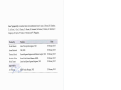
Issue No.
Issue Date
1
2
3
4
19 March 2012
24 August 2012
5 February 2013
5 July 2013
5
11 October 2013
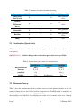
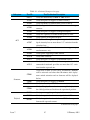
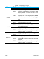
Revision Control
- Updated QB50-SYS-1.4.1 to define WOD as the following set of parameters: time, spacecraft mode, battery bus
voltage, battery bus current, current on regulated bus 3.3V,
current on regulated bus 5.0V, communication subsystem
temperature, EPS temperature and battery temperature.
- Added a recommendation for downlink-only ground station network compatibility in the OBC / OBDH section.
- Updated QB50-SYS-1.5.4 to indicate the information to
be included in telemetry downstream.
- Deleted QB50-SYS-1.5.10. The position accuracy requirement for the CubeSat is dependant upon the science
sensor which it is carrying and it is specified in the corresponding ICD.
- Updated QB50-SYS-1.5.11 to state the additional information that should be provided through the beacon.
- Updated QB50-SYS-1.5.13 to state where the data type
during downlink should be specified.
- Replaced Mission Display Centre section with QB50 Storage Server on page 22 as it was more appropriate.
- Updated QB50-SYS-1.7.9 to remove uncertainty in the
type of data that is to be sent to the QB50 storage server
by the teams.
- Removed paragraph about Mission Display Centre as it is
no longer relevant to this document.
- Added QB50-SYS-1.7.10.
Continued on next page
Issue 7
1
13 February 2015
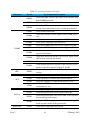
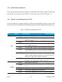
– Continued from previous page
Issue No.
Issue Date
Revision Control
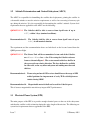
- Added a section on Science Operation Period containing
2 additional requirements: QB50-SYS-1.7.11 and QB50SYS-1.7.12.
6
9 July 2014
- Included additional reference documents (Cyclone-4 User
Manual, WOD packet format, Example umbilical connectors, SCS description and ICD)
- Updated deployment system terminology from StackPack
to QuadPack.
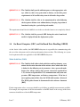
- Updated CubeSat Access Hatch section to clarify that the
access hatch is on the deployer and the access connector on
the CubeSat is to be smaller such that it could fit through
the hatch. To this end, a recommendation was added.
- Added QB50-SYS-1.1.9. This was always a requirement
but it was previously embedded within the text.
- Updated Mass section to state the upper mass limits are
from the QB50 Project, instead of the capabilities of the
QuadPack.
- Added remark after QB50-1.3.2.
- Updated the Whole Orbit Data (WOD) section to clarify
what is required for temperature values as part of the WOD.
- Updated QB50-SYS-1.4.5 such that OBSW and mission
support software is simplified to only OBSW.
- Updated QB50-SYS-1.4.6 to clarify that the infinite loops
mentioned in this requirement was referring to unintentional infinite loops.
- Updated QB50-SYS-1.4.7 to state “implemented” instead
of “foreseen”.
- Updated QB50-SYS-1.4.8 to be more clear on the type of
software that is to be on the CubeSat.
Continued on next page
Issue 7
2
13 February 2015
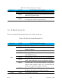
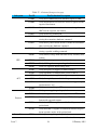
– Continued from previous page
Issue No.
Issue Date
Revision Control
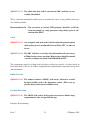
- Updated Satellite Control Software section to remove
DPAC and MCC and to indicate that the CubeSat teams will
be interacting with a QB50 central server for data uploading. Also, the ICD for the SCS provided by EPFL should
be consulted for teams that plan to use it.
- Added a recommendation to avoid encapsulating one protocol within another.
- Updated QB50-SYS-1.5.9.
- Updated Thermal Control section to state that the thermal
cycling levels are provided in Chapter 2
- Updated Apply Before Flight, Remove Before Flight items
section to state that the RBF and ABF tags should fit
through the access hatch and should be inserted / removed
only after integration into the deployer.
- Updated QB50-1.7.8 to specify what is meant by CubeSat
name.
- Removed all TBCs and TBDs from Chapter 1.
- Revised entire Chapter 2, the system requirement numbering has been kept consistent with issue 5 when possible.
- Added detailed quality assurance (QA) process in Chapter
3
- Unified names for QB50 central server and QB50 storage
server, now are all named QB50 central server.
- Updated Figure 3.
- Added QB50-SYS-1.4.9 to clarify science data deletion.
- Updated QB50-SYS-1.6.2.
- Updated QB50-SYS-1.5.14.
7
Issue 7
2 February 2015
- Updated DPAC acronym and deleted MDC.
- Reworded the “Important note” of Section 1 and added a
reference to QB50 website.
Continued on next page
3
13 February 2015
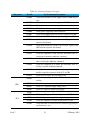
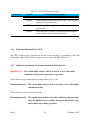
– Continued from previous page
Issue No.
Issue Date
Revision Control
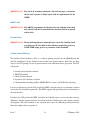
- Updated Applicable & Reference documents (Issue numbers and dates).
- Updated QB50-SYS-1.2.1, based on the Precursor campaign: higher tip-off rates, 3 days instead of 2.
- Added Recommendation 13, based on the Precursor campaign.
- Added Recommendation 14, based on the Precursor campaign.
- Updated QB50-SYS-1.4.1: additional details in case the
bus is not acquiring some values.
- In Recommendation 10, replaced QB50 central server by
DPAC.
- In paragraph “Satellite Control Software” p.24, replaced
central server by DPAC.
- In Recommendation 12, removed (1 week).
- QB50-SYS-1.5.12 turned into Recommendation 15.
- Added Recommendation 16, based on the Precursor campaign.
- Updated QB50-SYS-1.7.1: the required lifetime is now 6
months instead of 3.
- Subsection “QB50 Central server” p.30 became “QB50
Display, Processing, and Archiving Center (DPAC)”.
- Updated QB50-SYS-1.7.11: the duration for commissioning is now 1 month instead of 1 week.
- Updated QB50-SYS-1.7.12, added QB50-SYS-1.7.13,
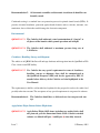
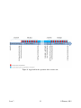
Recommendation 17, and Figure 6: the concept of operations is modified (every second day but for a longer period).
- Updated the introduction of Section 2 with orbital parameters.
- Added requirement QB50-SYS-2.0.1. This requirement
returns to the requirement of QB50 System Requirements
and Recommendations Issue 5.
Continued on next page
Issue 7
4
13 February 2015
– Continued from previous page
Issue No.
Issue Date
Revision Control
- In Table 6 (Acceleration test characteristics), the amplitude for qualification is modified to 13 g.
- In Table 7 (Resonance survey test characteristics), a clarification note is added.
- In Table 8 (Sinusoidal vibration test characteristics), the
test profile is modified (frequency range extended to 125
Hz, amplitudes modified).
- In Table 9 (Random vibration test characteristics), the duration is increased to 120 s for acceptance and protoflight
tests.
- In Table 9 (Random vibration test characteristics), the amplitude required for qualification is increased.
- In Table 10 (Shock test characteristics), the test profile for
protoflight is modified (lower loads).
- Section 2.9 is thoroughly revised to lighten the required
tests and provide guidelines for extensive EMC testing.
QB50-SYS-2.9.1 updated, QB50-SYS-2.9.2 and Recommendation 18 added.
- Modified introduction of Subsection 3.1.2, due to modification of Section 2.9.
- New Subsection 3.1.7 with additional requirements and
recommendations on functional tests.
- Added QB50-SYS-3.1.2 and Recommendation 19 for continuous testing (with representative durations) of the flight
software.
- Added Recommendation 20 for representative testing of
the ground station.
Issue 7
5
13 February 2015
Contents
List of acronyms
9
Applicable documents
11
Reference documents
13
1
14
2
CubeSat System Requirements
1.1
Structural Subsystem . . . . . . . . . . . . . . . . . . . . . . . . . . . . . . . . . 14
1.2
Attitude Determination and Control Subsystem (ADCS) . . . . . . . . . . . . . . 21
1.3
Electrical Power System (EPS) . . . . . . . . . . . . . . . . . . . . . . . . . . . . 21
1.4
On-Board Computer (OBC) and On-Board Data Handling (OBDH) . . . . . . . . 22
1.5
Telemetry, Tracking & Command . . . . . . . . . . . . . . . . . . . . . . . . . . 25
1.6
Thermal Control . . . . . . . . . . . . . . . . . . . . . . . . . . . . . . . . . . . . 28
1.7
General . . . . . . . . . . . . . . . . . . . . . . . . . . . . . . . . . . . . . . . . 28
Qualification and Acceptance Testing Requirements for Launch
33
2.1
Acceleration (Quasi-static) . . . . . . . . . . . . . . . . . . . . . . . . . . . . . . 34
2.2
Resonance Survey . . . . . . . . . . . . . . . . . . . . . . . . . . . . . . . . . . . 34
2.3
Sinusoidal Vibration . . . . . . . . . . . . . . . . . . . . . . . . . . . . . . . . . 35
2.4
Random Vibration . . . . . . . . . . . . . . . . . . . . . . . . . . . . . . . . . . . 36
2.5
Shock Loads . . . . . . . . . . . . . . . . . . . . . . . . . . . . . . . . . . . . . . 37
2.6
Mechanical Test Pass Criteria . . . . . . . . . . . . . . . . . . . . . . . . . . . . . 37
2.7
Thermal-Vacuum Test . . . . . . . . . . . . . . . . . . . . . . . . . . . . . . . . . 38
2.8
Thermal-Vacuum Bake Out . . . . . . . . . . . . . . . . . . . . . . . . . . . . . . 38
2.9
EMC Testing . . . . . . . . . . . . . . . . . . . . . . . . . . . . . . . . . . . . . 39
Issue 7
2.9.1
Radiated Emission . . . . . . . . . . . . . . . . . . . . . . . . . . . . . . 40
2.9.2
Radiated Susceptibility . . . . . . . . . . . . . . . . . . . . . . . . . . . . 40
7
13 February 2015
3
Quality Assurance and Reporting
3.1
42
Functional Tests . . . . . . . . . . . . . . . . . . . . . . . . . . . . . . . . . . . . 42
3.1.1
Reference Functional Tests (RFT) . . . . . . . . . . . . . . . . . . . . . . 44
3.1.2
Electromagnetic Compatibility Functional Tests . . . . . . . . . . . . . . . 48
3.1.3
Pre Thermal Vacuum Tests . . . . . . . . . . . . . . . . . . . . . . . . . . 50
3.1.4
Post Thermal Vacuum Tests . . . . . . . . . . . . . . . . . . . . . . . . . 53
3.1.5
Thermal Cycling Functional Tests (TCF) . . . . . . . . . . . . . . . . . . 53
3.1.6
Verification Functional Tests (VFT) . . . . . . . . . . . . . . . . . . . . . 55
3.1.7
Additional requirements and recommendations on functional tests . . . . . 55
3.2
End-to-End HIL Test . . . . . . . . . . . . . . . . . . . . . . . . . . . . . . . . . 56
3.3
Test Reporting . . . . . . . . . . . . . . . . . . . . . . . . . . . . . . . . . . . . . 57
Issue 7
8
13 February 2015
List of acronyms
1U, 2U, 3U
ABF
ACRR
AMSAT
BPSK
BRF
CalPoly
CDR
CMD
CSS
CVCM
DC
DPAC
EGSE
EM
EMC
EQM
ESD
FIPEX
FM
GS
GSE
HIL
HDRM
IARU
ICD
INMS
ISIS
LEOP
LRF
LV
MM
MNLP
MSSL
Issue 7
1-Unit, 2-Unit and 3-Unit CubeSat sizes, respectively
Apply Before Flight
Adjacent Channel Rejection Ratio
Amateur Radio Satellite
Binary Phase Shift Keying
Body Reference Frame
California Polytechnical State University, SLO
Critical Design Review
Command
Command Sequence Script
Collected Volatile Condensable Material
Direct Current
QB50 Display, Processing, and Archiving Centre
Electronic Ground Support Equipment
Electro-Magnetic
Electro-Magnetic Compatibility
Engineering / Qualification Model
Electro-Static Discharge
Flux-φ-Probe Experiment
Flight Model
Ground Station
Ground Support Equipment
Hardware-In-the-Loop
Hold Down and Release Mechanism
International Amateur Radio Union
Interface Control Document
Ion/ Neutral Mass Spectrometer
Innovative Solutions In Space BV
Launch and Early Orbit Phase
Launcher Reference Frame
Launch Vehicle
Mass Memory
Multi-Needle Langmuir Probe
Mullard Space Science Laboratory
9
13 February 2015
OBC
OBDH
OBSW
NPU
PCB
PDR
QA
QPSK
RBF
RE
RF
RFT
RS
SA
SCS
SLO
SU
TBC
TBD
TCF
TT&C
TML
UHF
VFT
VHF
VKI
WOD
Issue 7
On-Board Computer
On-Board Data Handling
On-Board Software
Northwestern Polytechnical University, China
Printed Circuit Board
Preliminary Design Review
Quality Assurance
Quadrature Phase Shift Keying
Remove Before Flight
Radiated Emission
Radio Frequency
Reference Functional Tests
Radiated Susceptibility
Signal Answer
Satellite Control Software
San Luis Obispo, California, United States of America
Sensor Unit
To Be Confirmed
To Be Determined
Thermal Cycling Functional
Telemetry, Tracking and Command
Total Mass Loss
Ultra High Frequency
Verification Functional Tests
Very High Frequency
von Karman Institute for Fluid Dynamics
Whole Orbit Data
10
13 February 2015
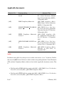
Applicable documents
Reference No.
[A01]
Document Name
Document Title
QB50-INMS-MSSL-ID-12001 Is- QB50 INMS Science Unit Intersue 10
face Control Document, Mullard
Space Science Laboratory (MSSL),
15 September 2014
[A02]
INMS Compliancy Matrix.xlsx
QB50 INMS Compliancy Matrix,
Mullard Space Science Laboratory
(MSSL), 15 September 2014
[A03]
ILR-RFS FPXQB50 ICD-1000-10
Issue 2.4
QB50 FIPEX Science Unit Interface Control Document, Technische
Universitat Dresden (TU Dresden),
30 September 2014
[A04]
FIPEX Compliancy Matrix.xlsx QB50 FIPEX Compliancy MaVersion 2
trix, Technische Universitat Dresden (TU Dresden), 15 September
2014
[A05]
QB50-UiO-ID-0001 M-NLP Issue QB50 MNLP Science Unit Inter4
face Control Document, University
of Oslo (UiO), 11 September 2014
[A06]
MNLP Compliancy Matrix.xlsx QB50 MNLP Compliancy Matrix,
Version 2
University of Oslo (UiO), 15
September 2014
NOTE:
In addition to this QB50 System Requirements and Recommendation - Issue 7 document, CubeSats
that carry the QB50 Science Unit have to adhere to their corresponding Interface Control Document
(ICD) and their Compliancy Matrix, which are listed in this (Applicable documents) section. That
is,
• CubeSats with an INMS shall also comply with [A01] - QB50 INMS Science Unit Interface
Control Document and [A02] - QB50 INMS Compliancy Matrix
• CubeSats with a FIPEX shall also comply with [A03] - QB50 FIPEX Science Unit Interface
Control Document and [A04] - QB50 FIPEX Compliancy Matrix
Issue 7
11
13 February 2015
• CubeSats with a MNLP shall also comply with [A05] - QB50 MNLP Science Unit Interface
Control Document and [A06] - QB50 MNLP Compliancy Matrix
Issue 7
12
13 February 2015
Reference documents
Reference No.
[R01]
Document Name
call proposals QB50.pdf
Document Title
Call for CubeSat Proposals for
QB50, von Karman Institute for
Fluid Dynamics (VKI), Brussels,
Belgium, 15 February 2012
[R02]
cds rev12.pdf
CubeSat Design Specification Rev.
12, The CubeSat Program, Cal Poly
SLO, 2009
[R03]
2 4 scholz.pdf 1
Recommended Set of Models and
Input Parameters for the Simulations of Orbital Dynamics of
the QB50 CubeSats T. Scholz,
C.O.Asma, A.Aruliah, 15 February
2012
[R04]
cyclone 4 users guide.pdf
Cyclone-4 Launch Vehicle Issue 1,
Alcantara Cyclone Space, Brasilia,
Brazil, Oct 2010
[R05]
QB50 Whole Orbit Data Iss4.pdf
Whole Orbit Data Packet Format,
Issue 4, von Karman Institute for
Fluid Dynamics (VKI), Brussels,
Belgium, October 2014
[R06]
Umbilical Options.pdf
Examples of Umbilical Connectors,
Innovative Solutions in Space B.V
(ISIS), Delft, Netherlands, 6 Dec
2013
[R07]
10 - QB50-EPFL-SSC-SCSICD-D2501-4-0.pdf
SCS description and interface control document Issue 4, Swiss Space
Center Ecole Polytechnique Federale de Lausanne (EPFL), Lausanne, Switzerland, 31 July 2014
1
This document is not fully up to date with respect to the orbit and the launch vehicle, however, the model is still
valid
Issue 7
13
13 February 2015
1
CubeSat System Requirements
IMPORTANT NOTE:
Please take the following points into account:
• In addition to the requirements stated in this document, all QB50 CubeSats shall also comply with the requirements specified in CalPoly’s CubeSat Design Specification, Rev 12
[R02]. However, if there is any contradiction (e.g mass), then the requirement in this document supersedes it. There does exist a CDS Rev 13 from Cal Poly, but the reference for
QB50 CubeSats is the Rev 12.
• In addition to the requirements stated in this document, the CubeSat teams shall comply with
the QB50 schedule and milestones (including reviews) as presented on the QB50 website
(https://www.qb50.eu).
• VHF downlinks cannot be used.
1.1
Structural Subsystem
Dimension
Several standard CubeSat sizes are identified in “Units” relative to the original 1-Unit CubeSat.
Only 2U and 3U CubeSats are anticipated for QB50. The dimensions are shown in Table 3.
QB50-SYS-1.1.1 CubeSats dimensions shall be as shown in Table 3.
Table 3: Generic CubeSat dimensions
Property
Footprint
Height
Feet
Rails
Issue 7
2U
100 × 100 ± 0.1 mm
227 ± 0.1 mm
8.5 × 8.5 ± 0.1 mm
External edges shall be rounded
R × 1mm or chamfered 45◦ × 1mm
14
3U
100 × 100 ± 0.1 mm
340.5 ± 0.1 mm
8.5 × 8.5 ± 0.1 mm
External edges shall be rounded
R × 1mm or chamfered 45◦ × 1mm
13 February 2015
Reference Frame
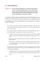
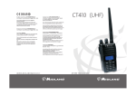
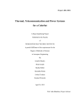
QB50-SYS-1.1.2 The CubeSats shall use the reference frame as shown in Figure 1
such that it will be in line with the reference frame of the deployment
system.
Figure 1: QB50 CubeSat reference frame
Issue 7
15
13 February 2015
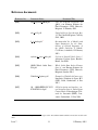
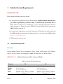
Extended Volumes
The QuadPack - the deployment system for the QB50 mission - can accommodate 2U and 3U
CubeSats. It provides extra volume to accommodate deployables, appendices, booms, antennas
and solar panels. It offers lateral clearance between the CubeSat lateral sides and the QuadPack
side panels. Moreover the QuadPack provides the capability to accommodate CubeSats with both,
front and back extended volumes. However, for the CubeSats carrying the Science Unit, only the
front could be used as the back extended volume is allocated for the Science Unit.
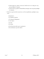
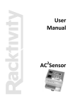
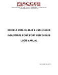
Figure 2 shows the QuadPack extended volumes provided for the QB50 CubeSats; lateral extensions (-X, +X, -Y and +Y) are depicted in green, while front one (+Z) in yellow and back one (-Z)
in blue.
Figure 2: CubeSats lateral (green), front (yellow) and back (blue) extended volumes.
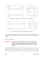
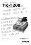
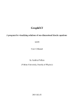
QB50-SYS-1.1.3 In launch configuration the CubeSat shall fit entirely within the extended volume dimensions shown in Figure 3 for a 2U CubeSat or
Figure 4 for a 3U CubeSat, including any protrusions.
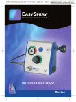
Figure 3 shows the maximum dimensions in millimetres allowed by the QuadPack for the QB50
2U CubeSat extended volumes. Note that these dimensions relate to the extended volumes of the
CubeSat and not the height of the guide rails of the CubeSat. The height is still 227 mm as stated
in Table 3.
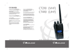
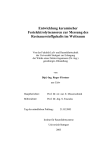
Figure 4 shows the maximum dimensions in millimetres allowed by the QuadPack for the QB50
Issue 7
16
13 February 2015
Figure 3: 2U CubeSat extended volume dimensions in millimetres.
Figure 4: 3U CubeSat extended volume dimensions in millimetres.
3U CubeSat extended volumes. Note that these dimensions relate to the extended volumes of the
CubeSat and not the height of the guide rails of the CubeSat. The height is still 340.5 mm as stated
in Table 3.
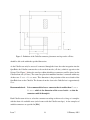
CubeSat Access Hatches
QB50-SYS-1.1.4 After integration into the QuadPack, the CubeSat shall only require
access, for any purpose, through the access hatches in the door of the
QuadPack. The position and dimensions of these hatches are shown
in Figure 5.
Remove Before Flight (RBF) tags should be able to be removed through these access hatches only.
Likewise, Apply Before Flight (ABF) tags should only be accessible via these access hatches.
These tags can only be removed / applied after integration into the QuadPack. Therefore they
Issue 7
17
13 February 2015
Figure 5: Definition of the CubeSat connector placement envelope on the +Z face.
should be able to fit within the specified dimension.
As the CubeSat can only be accessed / connected through the front door after integration into the
QuadPack, the CubeSat connector has to be on the front side (+Z face), which is opposite to the
Science Unit. Figure 5 defines the envelope within which these connectors could be placed on the
CubeSat front side (+Z face). The teams can place their umbilical interface / connector within any
of these two 25 mm × 13 mm areas. This dimension is the projection of the access hatch of the
QuadPack door on the CubeSat. The distance from the door to the CubeSat feet is approximately
1mm.
Recommendation 8:
It is recommended to have a connector that is smaller than 25 mm ×
13 mm – which is the dimension of the access hatch – so that the
connector could fit through it.
Each CubeSat team is free to select the connector according to their needs as long as it complies
with the front side available areas (and of course with the CubeSat envelope). A few examples of
suitable connectors are specified in [R06].
Issue 7
18
13 February 2015
QB50-SYS-1.1.9 Due to the wide range of possible solutions each team shall supply the
required Electrical Ground Support Equipment (EGSE) and harness.
Due to time and space constraints, only one access opportunity after integration of the CubeSat
into the QuadPack at ISIS will be granted to each team to perform all the required activities (data
connectivity, battery charge, checkout, etc). Afterward, in a nominal situation, no battery charging
or checkout will be performed. In a non-nominal situation, battery charging / checkout could
be performed - given that a proper user manual and procedure, EGSE is available - by a QB50
Consortium member. Although, the Consortium Board cannot take responsibility for the health of
the satellite.
Issue 7
19
13 February 2015
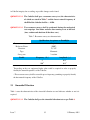
Mass
As stated previously, the QuadPack is designed to accommodate both 2U and 3U CubeSats. Table 4
states the specifications for the maximum masses of the different QB50 CubeSat that is allowed by
the QB50 Project.
QB50-SYS-1.1.5 The CubeSat mass shall be no greater than that shown in Table 4.
Table 4: CubeSat masses admitted by the QB50 Project
CubeSat Size Maximum Mass
2U CubeSat
2.0 kg
3U CubeSat
3.0 kg
Centre of Gravity
QB50-SYS-1.1.6 The CubeSat centre of gravity shall be located within a sphere of
20 mm diameter, centered on the CubeSat geometric centre.
This is required in order to control misalignment of the QuadPack centre of gravity position on the
launch vehicle.
Recommendation 1:
For aerodynamic stability, it is recommended to have the CubeSat
centre of gravity towards the face of the Science Unit (-Z face, which
will be in the spacecraft ram velocity direction) with respect to the
CubeSat geometric centre.
Deployment Switches
QB50-SYS-1.1.7 Deployment switches shall be non-latching (electrically or mechanically).
Material
QB50-SYS-1.1.8 The CubeSat rails and standoffs, which contact the QuadPack rails,
pusher plate, door, and/or adjacent CubeSat standoffs, shall be constructed of a material that cannot cold-weld to any adjacent materials.
Issue 7
20
13 February 2015
1.2
Attitude Determination and Control Subsystem (ADCS)
The ADCS is responsible for detumbling the satellite after deployment, pointing the satellite in
a favourable attitude to meet the mission requirements as well as for recovering it from any spin
ups during the mission. It is also responsible for determining the satellite’s attitude. System level
requirements that are applicable to the ADCS are the following:
QB50-SYS-1.2.1 The CubeSat shall be able to recover from tip-off rates of up to
±50◦ /s within 3 days (nominal conditions).
Recommendation 13:
The CubeSat shall be able to recover from tip-off rates of up to
±90◦ /s in off-nominal situation.
The requirement and the recommendation above are both based on the lessons learned from the
QB50 precursor flight.
QB50-SYS-1.2.2 The Science Unit will be accommodated at one end of the CubeSat,
on a 10 mm × 10 mm face — the -Z face using the CubeSat reference
frame as shown in Figure 1. The vector normal to this face shall be in
the spacecraft ram velocity direction. The face shall not be available
for solar cells, or for any other subsystem and nothing must forward
this face.
Recommendation 9:
Teams using on-board GPS receiver should foresee the usage of GPS
orbital positions for improvement of early TLEs with high uncertainties during LEOP.
Recommendation 14: Magnetizable material shall not be used for CubeSat parts.
This is because magnetizable materials may impact ADCS performances.
1.3
Electrical Power System (EPS)
The main purpose of the EPS is to provide enough electrical power to the rest of the subsystems
such that the satellite is able to function during the entire length of the mission. The following are
system level requirements that are applicable to the EPS:
Issue 7
21
13 February 2015
QB50-SYS-1.3.1 The CubeSat shall provide sufficient power at the appropriate voltage, either by solar array generation or battery, to meet the power
requirements of all satellite subsystems in all modes of operation.
QB50-SYS-1.3.2 The CubeSat shall be able to be commissioned in orbit following
the last powered-down state without battery charging, inspection or
functional testing for a period of up to 8 months.
This requirement should also be fulfilled even in the case that the batteries are completely drained.
QB50-SYS-1.3.3 The CubeSat shall be powered OFF during the entire launch and
until it is deployed from the deployment system.
1.4
On-Board Computer (OBC) and On-Board Data Handling (OBDH)
As the ‘brain’ of the satellite, the OBC/OBDH subsystem is responsible for communicating with
the rest of the subsystems and for relaying information between them. The following are system
level requirements that are applicable to the OBC/OBDH subsystem:
Whole Orbit Data (WOD)
QB50-SYS-1.4.1 The CubeSat shall collect whole orbit data and log telemetry every
minute for the entire duration of the mission, where whole orbit data
is defined as the following set of parameters: time, spacecraft mode,
battery bus voltage, battery bus current, current on regulated bus
3.3V, current on regulated bus 5.0V, communication subsystem temperature, EPS temperature and battery temperature. If the bus is
not acquiring some of this data, the WOD shall contain a 0 instead.
The WOD packet format is documented in the reference document
[R05].
For the temperature values, an average should be used if there are multiple measurements available.
For example, the temperature of the microcontroller on the EPS board or the average of the boost
converters should be used for the EPS temperature.
Issue 7
22
13 February 2015
QB50-SYS-1.4.2 The whole orbit data shall be stored in the OBC until they are successfully downlinked.
This is so that the information could be used to determine the causes of any problems in the case
of a CubeSat anomaly.
Recommendation 10:
The correctness of received WOD packages should be verified by
teams on ground (e.g. using parameter range checks) prior to submission to the DPAC.
Clock
QB50-SYS-1.4.3 Any computer clock used on the CubeSat and on the ground segment
shall exclusively use Coordinated Universal Time (UTC) as time reference.
QB50-SYS-1.4.4 The OBC shall have a real time clock information with an accuracy
of 500ms during science operation. Relative times should be counted
/ stored according to the epoch 01.01.2000 00:00:00 UTC.
This requirement requests real time clock information and not necessarily a real time clock on
board the CubeSat. The use of a GPS or an uplink clock synchronization command could provide
such information.
Inhibit Override
QB50-SYS-1.4.5 The onboard software (OBSW) shall not be allowed to override
hardware inhibits such as the deployment switch. (This is not applicable during check-out via umbilical cord).
Deadlock Prevention
QB50-SYS-1.4.6 The OBSW shall protect itself against unintentional infinite loops,
computational errors and possible lock ups.
Defensive Programming
Issue 7
23
13 February 2015
QB50-SYS-1.4.7 The check of incoming commands, data and messages, consistency
checks and rejection of illegal input shall be implemented for the
OBSW.
OBSW Code
QB50-SYS-1.4.8 The OBSW programmed and developed by the CubeSat teams shall
only contain code that is intended for use on that CubeSat on ground
and in orbit.
Scientific Data
QB50-SYS-1.4.9 Teams shall implement a command to be sent to the CubeSat which
can delete any SU data held in Mass Memory originating prior to a
DATE-TIME stamp given as a parameter of the command.
Satellite Control Software
The Satellite Control Software (SCS) is a software package provided by the QB50 Project that
could be implemented by the CubeSat teams on their own ground stations. Each team can have
access to the SCS package for use in ground stations under a bilateral license agreement. The SCS
will provide:
•
•
•
•
•
Ground station interface software
TM/TC Front End
CubeSat Control System
Operations User Interfaces software
Communications handling with the QB50 DPAC for science and WOD data uploading
It is not a requirement to use the SCS provided by EPFL, and teams may use an alternative solution
to meet the data downlink requirement. The DPAC supports file uploading and data uploading via
the web interface.
If utilized, the SCS provided by EPFL will allow the CubeSat teams to assist each other with any
difficulties with the common interface and will provide the CubeSat teams with a lighter software
development. This will contribute to the overall project success by offloading some ground tasks
that teams might not have expertise in.
Issue 7
24
13 February 2015
Another advantage is that the teams will benefit from compatibility with other teams and could
collaborate on their on-board software implementations. This option also facilitates the possibility
of using other teams ground stations. The software provided is extremely flexible and individual
teams can integrate their own specifics at many levels, for instance integrating their own payloadspecific data processing or visualization.
The SCS provided by EPFL has specific packet format and frame protocol which is defined in SCS
description and Interface Control Document [R07]. And teams that choose to use it will need to
comply with its requirements.
Recommendation 11:
It is recommended to avoid encapsulation of one protocol within another (e.g. AX.25 in CSP) to avoid increased overhead.
Ground Station Network
Recommendation 2:
1.5
It is recommended for the CubeSats to have the capability to schedule future autonomous downlinks such that it would be compatible
with potential downlink-only ground station networks.
Telemetry, Tracking & Command
Downlink
QB50-SYS-1.5.1 VHF shall not be used for downlink.
QB50-SYS-1.5.2 If UHF is used for downlink, the CubeSat shall use a downlink data
rate of at least 9.6 kbps.
QB50-SYS-1.5.3 If UHF is used for downlink, the transmission shall fit in 20 kHz at
-30 dBc, measured without Doppler, but over the entire operating
temperature range.
This will help ensure that each satellite can be quickly identified even at the start of the mission
when many or all of the spacecraft may be overhead a single ground station.
Issue 7
25
13 February 2015
QB50-SYS-1.5.4 All CubeSats shall have and make use of its unique satellite ID in the
telemetry downstream.
Recommendation 3:
It is recommended to implement BPSK or QPSK downlinks because
of their spectral efficiency.
Recommendation 4:
It is recommended to use different bands for uplink and downlink.
Uplink
QB50-SYS-1.5.5 If VHF is used for uplink, it shall have a data rate no greater than
1.2 kbps.
QB50-SYS-1.5.6 If UHF is used for uplink, it shall have a data rate no greater than
9.6 kbps.
QB50-SYS-1.5.7 All CubeSats shall have the capability to receive a transmitter shutdown command at all times after the CubeSat’s deployment switches
have been activated from QuadPack ejection.
QB50-SYS-1.5.8 Once a transmitter shutdown command is received and executed by
the CubeSat, a positive command from the ground shall be required
to re-enable the transmitter. Power reset (e.g. following eclipse)
should not re-enable the transmitter.
QB50-SYS-1.5.9 The CubeSat provider shall have access to a ground station which
has the capability and permission to send telecommands through an
uplink to control its satellite.
QB50-SYS-1.5.10 Requirement deleted from Issue 4
QB50-SYS-1.5.11 The CubeSat shall transmit the current values of the WOD parameters and its unique satellite ID through a beacon at least once every
30 seconds or more often if the power budget permits.
Issue 7
26
13 February 2015
Recommendation 12:
The beacon should be transmitted every 10 seconds during LEOP
phase to allow for multiple receptions of the beacon during a pass.
This procedure will assist the orbit determination and the identification of each Cubesat.
QB50-SYS-1.5.12 Requirement turned into a recommendation from Issue 7.
Recommendation 15:
If UHF is used for uplink, the radio receiver shall have an Adjacent
Channel Rejection Ratio (ACRR) of at least 100 dB.
This is to avoid possible blocking of the receiver or interference from nearby QB50 satellites.
Teams should also be aware that such operation will require very quick ( < 2ms) changeover time
between transmit and receive when working with short frames.
Downlink / Uplink Framing Protocol
QB50-SYS-1.5.13 The CubeSat shall use the AX.25 Protocol (UI Frames). The data
type during downlink shall be specified in the Secondary Station
Identifier (SSID) in the destination address field of the AX.25 frame.
Science data shall be indicated using 0b1111 and Whole Orbit Data
with 0b1110.
Since the identifier describing the source and the destination in the address field of the frames shall
be unique for each CubeSat and its ground station within QB50, the satellite ID for each CubeSat
can be assigned by the QB50 Project to the CubeSat teams after the frequency allocation and
coordination process. The radio call sign for the operating ground station will have to be obtained
locally by each team.
QB50-SYS-1.5.14 User-friendly and documented software consisting of a) CubeSat
data Frames Decoder b) CubeSat data Packet Decoder and c) CubeSat data Viewer that complies with radio amateur regulations shall
be made available to VKI 6 months before the nominal launch date.
This documented software will be made available to the public following the AMSAT regulations.
The data viewer can be skipped, if a documented spreadsheet/csv (incl. column header inforIssue 7
27
13 February 2015
mation) file will be generated by the decoder software, so the data can be viewed with external
software e.g. Excel.
1.6
Thermal Control
QB50-SYS-1.6.1 The CubeSat shall maintain all its electronic components within its
operating temperature range while in operation and within survival
temperature range at all other times after deployment.
The operational and survival temperature range for components will vary between teams based
on hardware specification. The thermal cycling levels for environmental testing are provided in
Chapter 2 of this document.
QB50-SYS-1.6.2 The CubeSat shall survive within the temperature range of −20◦ C
to +50◦ C from the time of launch until its end of life.
Recommendation 16:
1.7
Due to the lessons learned from the QB50 precursor campaign, it is
recommended for all QB50 CubeSats to have a battery heater.
General
Lifetime
QB50-SYS-1.7.1 The CubeSat shall be designed to have an in-orbit lifetime of at least
6 months.
Material Degradation
QB50-SYS-1.7.2 The CubeSat shall not use any material that has the potential to
degrade in an ambient environment during storage after assembly,
which could be as long as approximately 2 years.
Conformal Coating
Issue 7
28
13 February 2015
Recommendation 5:
All electronic assemblies and electronic circuit boards should be conformally coated.
Conformal coating is a standard low-cost protection process for printed circuit boards (PCBs). It
provides electrical insulation, protection against harsh elements such as solvents, moisture, contamination, dust or debris that could damage the electronic component.
Environmental
QB50-SYS-1.7.3 The CubeSat shall withstand a total contamination of 3.1 mg/m2 at
all phases of the launch vehicle ground operation and in flight.
QB50-SYS-1.7.4 The CubeSat shall withstand a maximum pressure drop rate of
3.92 kPa/sec.
Cleanliness, Handling, Storage and Shipment
The whole set of QB50 CubeSats will undergo checkout and integration into the QuadPack at ISO
Class 8 clean room ISIS facility.
QB50-SYS-1.7.5 If a CubeSat has any special requirement in terms of cleanliness,
handling, storage or shipment, these shall be communicated to
the QuadPack integrator (ISIS) and also be approved by ISIS, 12
months before delivery of the CubeSat and also highlighted in the
User Manual.
The requirement(s) shall be well justified and explained in the proposal in order to be studied and
possibly taken into account. The acceptance of any special requirement is not granted in advance.
Recommendation 6:
The CubeSats should have a dedicated case for transport and storage.
Apply Before Flight, Remove Before Flight items
QB50-SYS-1.7.6 Apply Before Flight (ABF) items, including tags and/or labels, shall
not protrude past the dimensional limits of the CubeSat extended
volumes (as defined in Figure 3 and Figure 4) when fully inserted.
Issue 7
29
13 February 2015
QB50-SYS-1.7.7 All Remove Before Flight (RBF) items shall be identified by a bright
red label of at least four square centimetres in area containing the
words “REMOVE BEFORE FLIGHT” or “REMOVE BEFORE
LAUNCH” and the name of the satellite (CubeSat QB50 ID) printed
in large white capital letters.
Both ABF and RBF tags that needs to be applied or removed should fit through the access hatch to
ensure a powered off state of the CubeSat. It should be inserted or removed after integration into
the QuadPack. Therefore, these labels should be able to fit through an area of 25 mm × 13 mm as
that is the dimension of the access hatch.
Naming
QB50-SYS-1.7.8 The CubeSat QB50 ID (e.g. BE05) shall be printed, engraved or otherwise marked on the CubeSat and visible through the access hatch
in the door of the QuadPack.
QB50 Display, Processing, and Archiving Center (DPAC)
QB50-SYS-1.7.9 The CubeSat provider shall transfer the whole orbit data and science
data to the DPAC within 24 hours following reception on the ground.
QB50-SYS-1.7.10 All of the whole orbit data and science data downlinked to the
ground shall be stored in the individual CubeSat server up to 6
months after the completion of the mission.
Model Philosophy
Recommendation 7:
It is recommended for CubeSat teams to adopt the Engineering
Qualification Model - Flight Model (EQM-FM) approach in building their CubeSat.
A qualification model (QM) is a prototype which is will undergo qualification test. A QM could
serve as a spare part replacement and moreover could be used to troubleshoot if a complex problem
occurs. This is especially useful if the problem occurs while the FM CubeSat is not accessible such as at the launch site, or in orbit. Hardware costs are usually low compared to the overall cost.
Issue 7
30
13 February 2015
Most launch vehicle providers prefer that the payload uses an EQM-FM approach. As such, the
levels for the qualification and acceptance testing are already available. Chapter 2 provides the
envelope of the qualification and acceptance testing levels. Even though Cyclone-4 is the selected
LV, the envelope environmental levels will be required to be used to ensure a robust design.
The ProtoFlight testing levels are an intermediate level between qualification and acceptance. More
details on the ProtoFlight testing levels are given in the description of each mechanical test to be
performed (see Chapter 2).
Science Operation Period
QB50-SYS-1.7.11 CubeSats carrying the standard atmospheric sensors shall be able
to commence the science payload operations within one month after
deployment in orbit.
QB50-SYS-1.7.12 The standard atmospheric sensors shall be operated every second
day for a period of 60 days, starting one month after deployment in
orbit.
QB50-SYS-1.7.13 The science operation phase shall be resumed after the CubeSat constellation has reached an altitude of approximately 300 km. This
event will be notified by VKI two weeks ahead of the event. The
standard atmospheric sensors shall be operated every second day
for a period of 60 days.
Recommendation 17:
The standard atmospheric sensors shall be operated every day during the science phases, also in between the two science phases and
after the second science phase to maximize the science return.
Figure 6 summarizes this approach for the operation of the science unit.
Issue 7
31
13 February 2015
Figure 6: Approach for the operation of the science unit.
Issue 7
32
13 February 2015
2
Qualification and Acceptance Testing Requirements for Launch
The CubeSat orbit is a circular orbit with an altitude of 400 km ±20 km, an inclination of 98.18±1◦ ,
and a local time of ascending node (LTAN) TBD. Due to the secondary payload status inherent to
CubeSats, flexibility regarding the orbit (and especially the LTAN) is required, resulting in the
following requirement 2 .
QB50-SYS-2.0.1 The CubeSat shall be compatible with any local time of ascending
node (LTAN).
This chapter describes the case qualification and acceptance testing requirements for EQM-FM
(Engineering/Qualification Model and Flight Model) or PFM (Proto-Flight Model) test philosophy.
For qualification of the CubeSat design, an EQM of the CubeSat has to be subjected to the required
qualification tests at qualification levels and durations as defined in this chapter. For acceptance
of the CubeSat, the FM of the CubeSat has to be subjected to the required acceptance tests at
acceptance levels and durations as defined in this chapter. The mentioned values correspond to the
ones required by the Launch Vehicle Provider.
IMPORTANT: All the CubeSats shall be subjected to the most severe level imposed by the
launch vehicle, characteristics of which are defined in the corresponding subsections, in all
three mutually perpendicular directions X, Y, Z of the satellite {BRF}.
IMPORTANT: To ensure the correct vibration loads, each CubeSat shall be tested while it is
integrated into a TestPOD. Because the ISIS QuadPack will be equipped with a custom designed dynamic rail, all the mechanical testing performed using a TestPOD without dynamic
rail are conservative.
At this stage, it is recommended for the teams to identify the facilities in which they will perform
the following tests for their CubeSat.
2
This requirement returns to the requirement of QB50 System Requirements and Recommendations Issue 5.
Issue 7
33
13 February 2015
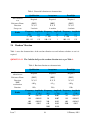
Table 5: Summary of required mechanical testing
2.1
Test category
Quasi-Static
and G-Loads
Natural
Frequencies /
Resonance
Survey
Qualification
Acceptance
Protoflight
X
-
X
X
X
X
Sinusoidal
X
X
X
Random
X
X
X
Shock
X
-
X
Testing method
FEM simulation
+ Test
FEM simulation
+ Test
FEM simulation
+ Test
FEM simulation
+ Test
Test
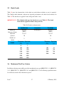
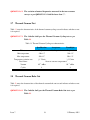
Acceleration (Quasi-static)
Table 6 states the characteristics of the acceleration (quasi-static) test and indicates whether or not
it is required.
QB50-SYS-2.1.1 CubeSat shall pass the acceleration (quasi-static) test as per Table 6.
Table 6: Acceleration (quasi-static) test characteristics
Reference Frame
Direction
Amplitude
Method
2.2
Qualification
Acceptance
Protoflight
{BRF}
X, Y, Z
13 g
Test
{BRF}
{BRF}
X, Y, Z
10.8 g
Test
Not Required
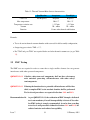
Resonance Survey
Table 7 states the characteristics of the resonance survey test and indicates whether or not it is
required. During the test, the CubeSat shall be integrated into a TestPOD which is attached to an
absolute rigid base. It is required (see QB50-SYS-2.2.2) to run a resonance survey test before and
after running a test at full level. By comparing the results of the resonance survey tests, a change
Issue 7
34
13 February 2015
in CubeSat integrity due to settling or possible damage can be found.
QB50-SYS-2.2.1 The CubeSat shall pass a resonance survey test, the characteristics
of which are stated in Table 7 and the lowest natural frequency of
the FM of the CubeSat shall be > 90 Hz.
QB50-SYS-2.2.2 Two resonance surveys shall be performed during the mechanical
test campaign. One before and one after running a test at full level
(sine, random and shock on all the three axes).
Table 7: Resonance survey test characteristics
Qualification, Acceptance or Protoflight
Required
{BRF}
X, Y, Z
Harmonic
2 oct/min
Resonance survey test
Reference Frame
Direction
Type
Sweep rate
Profile
Frequency, [Hz]
5
100∗∗
Amplitude, [g]
0.15∗
0.15∗
∗
Depending on the test equipment higher value could be required in order to properly
identify the natural frequencies of the CubeSat.
∗∗
The resonance survey shall be extended up to a frequency permitting to properly identify
the first natural frequency of the CubeSat.
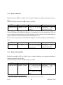
2.3
Sinusoidal Vibration
Table 8 states the characteristics of the sinusoidal vibration test and indicates whether or not it is
required.
QB50-SYS-2.3.1 The CubeSat shall pass the sinusoidal vibration tests as per Table 8.
Issue 7
35
13 February 2015
Table 8: Sinusoidal vibration test characteristics
Sine vibration
test
Reference Frame
Direction
Sweep rate
Profile
2.4
Qualification
Acceptance
Protoflight
Required
Required
Required
{BRF}
X, Y, Z
2 oct/min
{BRF}
X, Y, Z
4 oct/min
{BRF}
X, Y, Z
4 oct/min
Frequency, Amplitude, Frequency, Amplitude, Frequency, Amplitude,
[Hz]
[g]
[Hz]
[g]
[Hz]
[g]
5 - 100
2.5
5 - 100
2
5 - 100
2.5
100 - 125
1.25
100 - 125
1
100 - 125
1.25
Random Vibration
Table 9 states the characteristics of the random vibration test and indicates whether or not it is
required.
QB50-SYS-2.4.1 The CubeSat shall pass the random vibration tests as per Table 9.
Table 9: Random vibration test characteristics
Random
vibration test
Reference Frame
Direction
RMS
acceleration
Duration
Profile
Issue 7
Qualification
Acceptance
Protoflight
Required
Required
Required
{BRF}
X, Y, Z
{BRF}
X, Y, Z
{BRF}
X, Y, Z
8.03 g
6.5 g
8.03 g
120 s
120 s
120 s
Frequency,
[Hz]
20
130
800
2000
Amplitude, Frequency, Amplitude, Frequency, Amplitude,
[g2 /Hz]
[Hz]
[g2 /Hz]
[Hz]
[g2 /Hz]
0.01125
20
0.007
20
0.01125
0.05625
50
0.007
130
0.05625
0.05625
200
0.035
800
0.05625
0.015
640
0.035
2000
0.015
2000
0.010
36
13 February 2015
2.5
Shock Loads
Table 10 states the characteristics of the shock test and indicates whether or not it is required.
The CubeSat shall withstand, without any degraded performance, the shock levels indicated in
Table 10. The shock test is applied 2 times along each of the 3 axes.
QB50-SYS-2.5.1 The CubeSat shall pass the shock tests as per Table 10. The shock
loads shall be applied two times along each axis.
Table 10: Shock test characteristics
Qualification
Acceptance
Protoflight
Shock test
Required
Not Required
Required
Reference Frame
{BRF}
{BRF}
Direction
X, Y, Z
X, Y, Z
Q-factor
Number of
shocks
10
10
2
2
Frequency, Spectrum,
[Hz]
[g]
Frequency, Spectrum,
[Hz]
[g]
Profile
2.6
30
5
100
100
100
30
700
1500
1000
700
1000
2400
2000
700
1500
4000
5000
400
5000
4000
10000
2000
Mechanical Test Pass Criteria
In addition to having successfully passed the mechanical test as per QB50-SYS-2.1.1, QB50-SYS2.2.1, QB50-SYS-2.3.1, QB50-SYS-2.4.1 and QB50-SYS-2.5.1, the following requirement must
be satisfied to consider the vibration test passed.
Issue 7
37
13 February 2015
QB50-SYS-2.6.1 The variation of natural frequencies measured in the two resonance
surveys as per QB50-SYS-2.2.2 shall be lower than 5%.
2.7
Thermal-Vacuum Test
Table 11 states the characteristics of the thermal vacuum cycling test and indicates whether or not
it is required.
QB50-SYS-2.7.1 The CubeSat shall pass the Thermal Vacuum Cycling tests as per
Table 11.
Table 11: Thermal Vacuum Cycling test characteristics
TVac test
Acceptance
Protoflight
Required
Not Required
Required
Min temperature
-20±2 C
-20±2o C
Max temperature
50±2o C
50±2o C
Temperature variation rate
Dwell time
2.8
Qualification
o
≥1o C/min
≥1o C/min
1 hour at extreme temperatures
Vacuum
10−5 mBar
10−5 mBar
Cycles
4
4
Thermal-Vacuum Bake Out
Table 12 states the characteristics of the thermal vacuum bake out test and indicates whether or not
it is required.
QB50-SYS-2.8.1 The CubeSat shall pass the Thermal Vacuum Bake Out tests as per
Table 12.
Issue 7
38
13 February 2015
Table 12: Thermal Vacuum Bake Out test characteristics
TVAC test
Qualification
Acceptance
Protoflight
Not Required
Required
Required
o
Max temperature
50±2 C
50±2o C
Temperature variation rate
≥1o C/min
≥1o C/min
10−5 mBar
10−5 mBar
3 hours after thermal stabilization
Vacuum
Duration
Remarks:
• Test to be run in thermal vacuum chamber with test model in full assembly configuration;
• Outgassing pass criteria: TML < 1%;
• Pre TVAC and post TVAC test required before and after thermal vacuum tests (as per Table
13).
2.9
EMC Testing
The EMC tests are required in order to ensure that a single satellite element does not generate
interferences with other spacecraft components.
QB50-SYS-2.9.1 CubeSats subsystems and components shall not have electromagnetic emissions generating self-interferences with other subsystem/components.
QB50-SYS-2.9.2 If during the functional test a potential self-interference will be identified, a complete EMC test in anechoic chamber shall be performed.
Test levels and procedures are reported in Sections 2.9.1 and 2.9.2.
Recommendation 18:
Issue 7
As per QB50-SYS-2.9.2, the verification of EMC through a dedicated
test is not mandatory if no self-incompatibility is detected. Nevertheless EMC testing is strongly recommended: it can be done according
to test levels and procedures defined in Sections 2.9.1 and 2.9.2, for
radiated emission and radiated susceptibility
39
13 February 2015
2.9.1
Radiated Emission
Radiated emission (RE) test shall be done in anechoic chamber at ambient temperature and pressure.
CubeSats shall pass electric field RE testing as per Table:
EM Test
Frequency Range
RE Electric Field
30 MHz - 1 GHz
Limit
Remarks
50dBµV /m at all frequencies
Procedures:
refer
ECSS-E-ST-20-07C
to
Test for DC Magnetic Field Radiated Emission is recommended (even if not mandatory). This test
can be useful for characterization of CubeSat magnetic features (generated and residual magnetic
dipole, permanent or induced magnetic field of components, etc.).
In case, the test should verify a maximum DC magnetic emission according to the following features:
EM Test
Frequency Range
RE Electric Field
DC
2.9.2
Limit
Remarks
0.2µT at 1m distance
from each face
Procedures:
refer
ECSS-E-ST-20-07C
to
Radiated Susceptibility
Radiated susceptibility (RS) test shall be done in anechoic chamber or reverberation chamber at
ambient temperature and pressure.
CubeSats shall pass electric field RS testing as per Table :
EM Test
Frequency Range
Value
Remarks
RS Electric Field
30 MHz - 10 GHz
10V /m outside the main
frame or at proximity of
beams
1V /m inside the main
frame3
Procedures:
refer
ECSS-E-ST-20-07C
3
to
Optional requirement, depending on accessibility of internal parts for measurements.
Issue 7
40
13 February 2015
Pass criteria for CubeSat is to successfully perform functional EMC test as per section 3.1.2, without any degraded performance of electronic subsystems (especially high frequency electronics)
under the EM environment defined above.
Test for low frequencies magnetic field RS is recommended but not mandatory. The test can be
performed with Helmoltz coils only, according to MIL-STD-461F, section 5.19.4.
Issue 7
41
13 February 2015
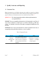
3
Quality Assurance and Reporting
3.1
Functional Tests
High level functional tests on CubeSats subsystems and assemblies are required for validation.
Functionality of the components shall be verified in different moments during the acceptance campaign. Six different sets of functional tests have been identified and listed in Table 13.
QB50-SYS-3.1.1 The Cubesat functionalities shall be verified using the functional test
sets reported in Table 13.
REMARK: The way to accomplish each functional test is left intentionally to each Team. It
can be a direct verification (e.g. digital scopes) or an indirect verification (e.g. OBC values
reading). It is forbidden at any time to disassemble or manipulate the QB50 Sensor Unit
Hardware.
IMPORTANT: In case one or more functional tests cannot be performed because they are
not applicable to the specific Cubesat hardware, a waiver is required.
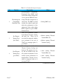
Table 13: Functional Test Sets
Set
1
Test Set
Description
When
Reference
Functional Tests
(RFT)
This sequence of tests shall be
the reference for CubeSat performances and term of comparison
for tests performed in the following phases.
• Beginning of acceptance
campaign or protoflight
testing campaign.
Continued on next page
Issue 7
42
13 February 2015
Table 13 – Continued from previous page
Set
2
3
4
Test Set
Description
Electromagnetic
Compatibility
Functional Tests
Electromagnetic Compatibility
Functional Tests (EMC) shall
ensure that CubeSat components
do not generate EM fields interfering with other components or
subsystems. The EMC test shall
measure the emitted signals and
check the performances of the
subsystems. Only a subset of the
RFT is required as part of EMC
functional tests.
Pre Thermal
Vacuum Tests
(Pre-TVAC)
Tests to be performed, before
both Thermal Vacuum Cycling
and bake out. Those set of
tests shall be compared with the
tests performed at the end of
TVAC test campaign (phase 5,
post TVAC).
Post Thermal
Vacuum Tests
(post TVAC)
Tests to be performed after both
Thermal Vacuum Cycling and
bake out. The purpose is to verify that the thermal loads and
the vacuum environment do not
modify system performances or
functionalities. Results of tests
shall be compared with set 4
tests (pre TVAC).
When
• During EMC tests.
• Before running Thermal
Vacuum Bake out;
• Before running Thermal
Vacuum Cycling.
• After running Thermal
Vacuum Bake out;
• After running Thermal
Vacuum Cycling.
Continued on next page
Issue 7
43
13 February 2015
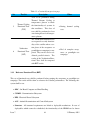
Table 13 – Continued from previous page
Set
5
6
3.1.1
Test Set
Description
When
Thermal Cycling
Functional Tests
(TCF)
Tests to be performed during
Thermal Vacuum Cycling at
temperatures plateau to check
the functionality of systems in
that conditions. This class of
tests shall be performed at least
once during hot and cold temperatures plateaus.
• During thermal cycling
tests.
Verification
Functional Tests
(VFT)
The verification functional tests
are requested to verify functionality of the satellite when a certain phase of the acceptance or
protoflight test campaign is completed. They can be used as additional pass/fail criteria. The
results of the Verification Functional Tests shall be compared
with RFT results.
• End of complete acceptance or protoflight test
campaign.
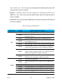
Reference Functional Tests (RFT)
This set of functional tests shall be performed before running the acceptance or protoflight test
campaign. The results will be taken as reference for CubeSat performances. The following subsystem shall be test:
• OBC - On Board Computer and Data Handling
• COMM - Communication Subsystem
• EPS - Electrical Power Subsystem
• ACS - Attitude Determination and Control Subsystem
• Structure - All structural requirements are linked to deployable mechanism. In case of
deployables which cannot be refurbished, the functionality of the HDRM can be shown
Issue 7
44
13 February 2015
with a dummy device. If it is not present any deployable mechanism, please ignore this
subsystem and no waiver is required.
• Payload - Considering as Payload any other instrument or electronic board which is not a
QB50 Sensor Unit. If it is not present any Payload, please ignore this subsystem and no
waiver is required.
• Sensor Unit - If it is not present any QB50 Sensor Unit, please ignore this subsystem and
no waiver is required.
Table 14: Reference Function Test
Subsystem
Test ID
OBC01
OBC02
OBC03
OBC04
OBC
OBC05
OBC06
OBC07
OBC08
COM01
COM02
COMM
Test/Verification Description
Verify that EPS supplies power to OBC board(s).
Verify that OBC receives power and commands through
umbilical connector.
Verify that OBC transmits data to COMM subsystem.
Verify that OBC receives and stores in the memory data
from COMM subsystem.
Verify that OBC can access and read data stored in memory.
Verify that OBC can read, store and transmit to COMM subsystem, data coming from sensors or subsystems boarded.
Verify that OBC sends activation command to deployables
(such as booms, antennas, panels etc.) not before than 30
minutes after deployment switches activation.
Verify that OBC activates RF transmitters not before than
30 minutes after deployment switches activation.
Verify antenna connection.
Verify that antennas receive signals from COMM subsystem.
COM03
Verify that antennas transmits signals to COMM subsystem.
COM04
Verify that antennas receives signals from external sources.
COM05
Verify that antennas transmits signals to external receivers.
COM06
Verify power supplying to the transceiver.
COM07
Verify that COMM subsystem receives signals from OBC.
Continued on next page
Issue 7
45
13 February 2015
Table 14 – Continued from previous page
Subsystem
Test ID
COM08
COM09
COM10
COM11
COM12
COM13
COM14
COM15
COM16
COM17
EPS01
EPS02
EPS03
EPS
EPS04
Test/Verification Description
Verify that COMM subsystem transmits signals to OBC.
Verify that transceiver decodes the received signals into the
expected data format.
Verify that transceiver encodes the received signals from
OBC into the expected data format.
Verify transceiver modulation.
Verify the capability to shut down the transmitter after receiving the transmitter shutdown command.
Verify that a power reboot doesnt re-enable the transmitter
after receiving the shutdown command.
Verify the capability to re-enable the transmitter after receiving a specific enabling command.
Verify and record that the transceiver operates in the expected (and officially IARU assigned) frequencies both in
Tx and Rx.
Verify beacon timing and transmitted data.
Verify and establish communications with the ground station.
Verify that batteries can be charged through the external
umbilical connector.
Verify battery voltage both with GSE and by telemetry data
reading.
Verify battery full charge and discharge cycle.
Verify battery voltage both with GSE and by telemetry data
reading after a complete charge and discharge cycle.
EPS05
Verify battery temperature readings by telemetry.
EPS06
Verify batteries connection.
EPS07
Verify 3.3V regulator output voltage level.
EPS08
Verify 5V regulator output voltage level.
Verify that solar panels provides expected voltage and
power outputs when enlightened.
EPS09
EPS10
Verify that solar panels can recharge the batteries.
Continued on next page
Issue 7
46
13 February 2015
Table 14 – Continued from previous page
Subsystem
Test ID
EPS11
Verify the functionality of RBF or ABF devices.
ACS01
Verify that power is supplied to ADCS board(s).
ACS02
Verify capability to enable/disable power to ADCS.
Verify magnetic field intensity measurements of magnetometers.
ACS03
ACS04
Verify that power is supplied to magneto-torquers.
ACS05
Verify the capability to enable/disable power to coils.
ACS06
Verify polarity of magneto-torquers.
Verify that all magneto-torquers magnetic field and/or
dipole intensity has no more than a 10% variation from the
calculated one.
Verify that ADCS sensors data are consistent (gyroscopes,
accelerometers, etc).
ACS
ACS07
ACS08
ACS09
Verify power supplying to GPS antenna.
ACS10
Verify GPS telemetry.
ACS11
Verify that power is supplied to momentum wheels.
Verify that the momentum wheels are operational and the
commanded rotational speed has no more than 10% variation from the expected one.
ACS12
Structure
STR01
Verify that all hold on and release mechanisms (HDRM)
will be activated not before than 30 minutes after deployment switch activation and no elements will be deployed
before.
STR02
Verify that power is supplied to HDRM.
STR03
Verify functionality of HDRM.
Verify all deployable mechanisms are capable deploy from
the folded position and lock into the operational position.
STR04
Payload
Test/Verification Description
PLU01
Verify power supplying to the payload.
PLU02
Verify that payload unit receives signals from OBC.
Verify that payload unit sends data to OBC in the expected
format with expected content.
PLU03
Continued on next page
Issue 7
47
13 February 2015
Table 14 – Continued from previous page
Subsystem
Test ID
PLU04
PLU05
SEU01
Verify power supplying to the payload.
SEU02
Verify that payload unit receives signals from OBC.
Verify that payload unit sends data to OBC in the expected
format with expected content.
Verify that OBC is capable to enable/disable power to the
payload unit.
Verify that OBC is capable to activate/deactivate/swap different operative modes of the payload unit.
Verify that the OBC can read/switch correctly between the
different time tagged scripts.
Verify that OBC/SU handles single script at end-of-day
time-roll-over.
SEU03
SEU04
Sensor Unit
SEU05
SEU06
SEU07
3.1.2
Test/Verification Description
Verify that OBC is capable to enable/disable power to the
payload unit.
Verify that OBC is capable to activate/deactivate/swap different operative modes of the payload unit.
Electromagnetic Compatibility Functional Tests
Test to be performed only if QB50-SYS-2.9.2 applies or if a full EMC test campaign is executed
(as per recommendation 18). To be performed in adequate facilities which can shield external EM
fields, at ambient pressure and temperature (please refer to sections 2.9.1 and 2.9.2).
Table 15: EMC Functional Tests
Subsystem
OBC
Test ID
Test/Verification Description
OBC01
Verify that EPS supplies power to OBC board(s).
OBC03
Verify that OBC transmits data to COMM subsystem.
Continued on next page
Issue 7
48
13 February 2015
Table 15 – Continued from previous page
Subsystem
Test ID
OBC04
OBC05
OBC06
COM01
COM02
COMM
Verify power supplying to the transceiver.
COM07
Verify that COMM subsystem receives signals from OBC.
COM08
Verify that COMM subsystem transmits signals to OBC.
Verify that transceiver decodes the received signals into the
expected data format.
Verify that transceiver encodes the received signals from
OBC into the expected data format.
COM15
Verify transceiver modulation.
Verify that the transceiver operates in the expected (and officially assigned) frequencies both in Tx and Rx.
EPS02
Verify battery voltage both with GSE and by telemetry data
reading.
ACS01
Verify that power is supplied to ADCS board(s).
ACS02
Verify capability to enable/disable power to ADCS.
ACS05
Verify the capability to enable/disable power to coils.
Verify that ADCS sensors data are consistent (gyroscopes,
accelerometers, etc).
ACS08
PLU01
Verify power supplying to the payload.
PLU02
Verify that payload unit receives signals from OBC.
Verify that payload unit sends data to OBC in the expected
format with expected content.
Verify that OBC is capable to activate/deactivate/swap different operative modes of the payload unit.
PLU03
PLU05
Sensor Unit
Verify antenna connection.
Verify that antennas receive signals from COMM subsystem.
COM06
COM11
Payload
Verify that OBC can access and read data stored in memory.
Verify that OBC can read, store and transmit to COMM subsystem, data coming from sensors or subsystems boarded.
Verify that antennas transmits signals to COMM subsystem.
COM10
ACS
Verify that OBC receives and stores in the memory data
from COMM subsystem.
COM03
COM09
EPS
Test/Verification Description
SEU01
Verify power supplying to the payload.
Continued on next page
Issue 7
49
13 February 2015
Table 15 – Continued from previous page
Subsystem
Test ID
SEU02
SEU03
SEU05
3.1.3
Test/Verification Description
Verify that payload unit receives signals from OBC.
Verify that payload unit sends data to OBC in the expected
format with expected content.
Verify that OBC is capable to activate/deactivate/swap different operative modes of the payload unit.
Pre Thermal Vacuum Tests
Test to be performed before thermal vacuum tests (cycling or bake out).
Table 16: Pre Thermal Vacuum Functional Test
Subsystem
Test ID
OBC01
Verify that EPS supplies power to OBC board(s).
OBC02
Verify that OBC receives power and commands through
umbilical connector.
Verify that OBC transmits data to COMM subsystem.
OBC03
OBC04
OBC
OBC05
OBC06
OBC07
OBC08
COMM
Test/Verification Description
COM01
Verify that OBC receives and stores in the memory data
from COMM subsystem.
Verify that OBC can access and read data stored in memory.
Verify that OBC can read, store and transmit to COMM subsystem, data coming from sensors or subsystems boarded.
Verify that OBC sends activation command to deployables
(such as booms, antennas, panels etc.) not before than 30
minutes after deployment switches activation.
Verify that OBC activates RF transmitters not before than
30 minutes after deployment switches activation.
Verify antenna connection.
Continued on next page
Issue 7
50
13 February 2015
Table 16 – Continued from previous page
Subsystem
Test ID
COM03
Verify that antennas receive signals from COMM subsystem.
Verify that antennas transmits signals to COMM subsystem.
COM04
Verify that antennas receives signals from external sources.
COM05
Verify that antennas transmits signals to external receivers.
COM06
Verify power supplying to the transceiver.
COM07
Verify that COMM subsystem receives signals from OBC.
COM08
Verify that COMM subsystem transmits signals to OBC.
COM09
Verify that transceiver decodes the received signals into the
expected data format.
Verify that transceiver encodes the received signals from
OBC into the expected data format.
Verify transceiver modulation.
COM02
COM10
COM11
COM12
COM13
COM14
COM15
COM16
ACS
Verify the capability to shut down the transmitter after receiving the transmitter shutdown command.
Verify that a power reboot doesnt re-enable the transmitter
after receiving the shutdown command.
Verify the capability to re-enable the transmitter after receiving a specific enabling command.
Verify that the transceiver operates in the expected (and officially assigned) frequencies both in Tx and Rx.
Verify beacon timing and transmitted data.
EPS05
Verify battery voltage both with GSE and by telemetry data
reading.
Verify battery temperature readings by telemetry.
EPS07
Verify 3.3V regulator output voltage level.
EPS08
Verify 5V regulator output voltage level.
ACS01
Verify that power is supplied to ADCS board(s).
ACS02
Verify capability to enable/disable power to ADCS.
ACS04
Verify that power is supplied to magneto-torquers.
ACS05
Verify the capability to enable/disable power to coils.
ACS08
Verify that ADCS sensors data are consistent (gyroscopes,
accelerometers, etc).
EPS02
EPS
Test/Verification Description
Continued on next page
Issue 7
51
13 February 2015
Table 16 – Continued from previous page
Subsystem
Test ID
Test/Verification Description
ACS09
Verify power supplying to GPS antenna.
ACS11
Verify that power is supplied to momentum wheels.
ACS12
Verify that the momentum wheels are operational and the
commanded rotational speed has no more than 10% variation from the expected one.
STR01
STR03
Verify that all hold on and release mechanisms (HDRM)
will be activated not before than 30 minutes after deployment switch activation and no elements will be deployed
before.
Verify functionality of HDRM.
PLU01
Verify power supplying to the payload.
PLU02
Verify that payload unit receives signals from OBC.
PLU03
Verify that payload unit sends data to OBC in the expected
format with expected content.
Verify that OBC is capable to enable/disable power to the
payload unit.
Verify that OBC is capable to activate/deactivate/swap different operative modes of the payload unit.
Structure
Payload
PLU04
PLU05
Sensor Unit
SEU01
Verify power supplying to the payload.
SEU02
Verify that payload unit receives signals from OBC.
SEU03
Verify that payload unit sends data to OBC in the expected
format with expected content.
Verify that OBC is capable to enable/disable power to the
payload unit.
Verify that OBC is capable to activate/deactivate/swap different operative modes of the payload unit.
SEU04
SEU05
Issue 7
52
13 February 2015
3.1.4
Post Thermal Vacuum Tests
Tests to be performed after thermal vacuum test campaign. Results shall be compared with results
of pre TVAC tests. Sequence of post TVAC tests is the same as the pre TVAC (Section 3.1.3).
3.1.5
Thermal Cycling Functional Tests (TCF)
Tests to be performed in vacuum conditions in a thermal vacuum chamber. The test sequence shall
be run at least once for maximum and minimum temperature plateaus during thermal cycling tests.
Table 17: Thermal Cycling Functional Test
Subsystem
Test ID
OBC01
Verify that EPS supplies power to OBC board(s).
OBC02
Verify that OBC receives power and commands through
umbilical connector.
Verify that OBC transmits data to COMM subsystem.
OBC03
OBC04
OBC
OBC05
OBC06
OBC07
OBC08
COMM
Test/Verification Description
Verify that OBC receives and stores in the memory data
from COMM subsystem.
Verify that OBC can access and read data stored in memory.
Verify that OBC can read, store and transmit to COMM subsystem, data coming from sensors or subsystems boarded.
Verify that OBC sends activation command to deployables
(such as booms, antennas, panels etc.) not before than 30
minutes after deployment switches activation.
Verify that OBC activates RF transmitters not before than
30 minutes after deployment switches activation.
COM01
Verify antenna connection.
COM02
COM03
Verify that antennas receive signals from COMM subsystem.
Verify that antennas transmits signals to COMM subsystem.
COM06
Verify power supplying to the transceiver.
COM07
Verify that COMM subsystem receives signals from OBC.
Continued on next page
Issue 7
53
13 February 2015
Table 17 – Continued from previous page
Subsystem
Test ID
COM08
Verify that COMM subsystem transmits signals to OBC.
COM09
Verify that transceiver decodes the received signals into the
expected data format.
Verify that transceiver encodes the received signals from
OBC into the expected data format.
Verify transceiver modulation.
COM10
COM11
COM12
COM13
COM14
ACS
Payload
EPS05
EPS07
Verify 3.3V regulator output voltage level.
EPS08
Verify 5V regulator output voltage level.
ACS01
Verify that power is supplied to ADCS board(s).
ACS02
Verify capability to enable/disable power to ADCS.
ACS04
Verify that power is supplied to magneto-torquers.
ACS05
Verify the capability to enable/disable power to coils.
ACS08
ACS09
Verify that ADCS sensors data are consistent (gyroscopes,
accelerometers, etc).
Verify power supplying to GPS antenna.
PLU01
Verify power supplying to the payload.
PLU02
Verify that payload unit receives signals from OBC.
PLU03
Verify that payload unit sends data to OBC in the expected
format with expected content.
Verify that OBC is capable to enable/disable power to the
payload unit.
Verify that OBC is capable to activate/deactivate/swap different operative modes of the payload unit.
PLU04
PLU05
Sensor Unit
Verify the capability to shut down the transmitter after receiving the transmitter shutdown command.
Verify that a power reboot doesnt re-enable the transmitter
after receiving the shutdown command.
Verify the capability to re-enable the transmitter after receiving a specific enabling command.
Verify battery voltage both with GSE and by telemetry data
reading.
Verify battery temperature readings by telemetry.
EPS02
EPS
Test/Verification Description
SEU01
Verify power supplying to the payload.
Continued on next page
Issue 7
54
13 February 2015
Table 17 – Continued from previous page
Subsystem
Test ID
Test/Verification Description
SEU02
Verify that payload unit receives signals from OBC.
SEU03
Verify that payload unit sends data to OBC in the expected
format with expected content.
Verify that OBC is capable to enable/disable power to the
payload unit.
Verify that OBC is capable to activate/deactivate/swap different operative modes of the payload unit.
SEU04
SEU05
3.1.6
Verification Functional Tests (VFT)
The VFT is requested to be performed at the end of the acceptance or protoflight to verify full
functionality of the CubeSat. The test sequence is the same as the RFT (Section 3.1.1).
3.1.7
Additional requirements and recommendations on functional tests
QB50-SYS-3.1.2 The satellite flight software shall be tested for at least 14h satellite
continuous up-time under representative operations.
This is because a typical time between ground station passes is 12h.
Recommendation 19:
The satellite flight software shall be tested for at least 30h satellite
continuous up-time.
This is because a science script lasts for 24h.
Recommendation 20:
Issue 7
The ground station shall be tested with a satellite in orbit (preferably
using the QB50 Precursor satellites) for up and downlink to verify,
among others, the tracking procedure.
55
13 February 2015
3.2
End-to-End HIL Test
QB50-SYS-3.2.1 CubeSats boarding the QB50 Sensors Unit shall perform an End-toEnd test, to verify the functionality of the sensors and the interfaces
with the CubeSat subsystems. Detailed procedure will be given in the
User Manual shipped with the Sensor Unit hardware. An overview
of the testing procedures is listed below as example.
A test should be structured as follows on an engineering model (or equivalent) fully representative
of the flight model with Sensor Unit (with dummy sensor head, if present). The content of scripts
to be run by the CubeSat team will be given by the SU provider. To consider the Sensor Unit
End-to-End HIL test as successful, the following tasks shall be accomplished based on continuous
operation of the CubeSat:
1. Load 7 scripts to the CubeSat via radio link, and show that each of the 7 scripts runs at the
correct date and time. For testing purposes, the start time of each script shall 10 mins from
the last script start time.
2. A script shall be loaded to the CubeSat and left to run past midnight (UTC time) to prove
that it correctly handles continuous operation, and roll-over to the next day.
• The OBC shall run this script at the correspondent tagged times, interpreting the OBC
commands to power the SU ON/OFF and forwarding the SU commands to the Science
Unit.
• Data packets shall be generated by the SU, received by the OBC and stored in the
CubeSat memory.
• SU data shall be downlinked via the CubeSat radio link to the ground station (or equivalent) when commanded (if power requirements allow then during SU operation, or
else when SU is OFF).
3. Two scripts shall be loaded to the CubeSat and left to run to show that the first script is
replaced by the second script at the correct date and time (at midnight in this test), as given
in the script header information.
• The OBC shall run these scripts at the appropriately tagged times, interpreting the OBC
commands to power the SU ON/OFF and forwarding the SU commands to the Science
Unit.
Issue 7
56
13 February 2015
• Data packets shall be generated by the SU, received by the OBC and stored in the
CubeSat memory without overwriting SU data that has not been transmitted to the
ground station
• SU data shall be downlinked via the CubeSat radio link to the ground station when
commanded (if power requirements allow then during SU operation, or else when SU
is OFF). This should include SU data from a previous day.
4. A command sent to the CubeSat, shall delete any SU data in MM-#1 prior to a given DATETIME stamp.
5. Demonstrate that SU data in MM-#2 can be downloaded via radio link. (This could be the
data deleted from MM-#1 previously).
The data received shall then be compared with the expected values. List of test commands and
relative expected answers will be provided with the Sensor Units, together with a detailed test
procedure, description of needed GSE, pass/fail criteria etc. In addition to the End-to-End tests,
depending on the boarded SU, some other functional test could be required (e.g. to test for correct SU data headers, or that the OBC is capable to read, process, store and send to COMM an
unexpected signal coming from the SU, or system robustness with respect to inconsistent signals,
etc.).
3.3
Test Reporting
The following verification campaign reports are requested:
1. Qualification Campaign Report/Acceptance campaign report (or alternatively Protoflight test
campaign report)
• Requirements
• Description of test sequence
• Test timing and deviations from the expected schedule
• Test summary (brief informations about all the performed tests)
• Statement of pass/fail criteria
• Non-conformance report
Issue 7
57
13 February 2015
• CubeSat uptime log (number of hours the CubeSat has been on during the acceptance/protoflight test campaign)
• CubeSat reboots log (number of Satellite Reboots during the entire acceptance/protoflight
test campaign)
2. Detailed test report for all the executed tests, at all level (qualification, protoflight or acceptance).
• Requirements
• Test facilities description
• Test Setup and Configurations
• Loads adopted
• Test flow
• Test results
• Pass/fail statement with respect to requirements
• Non-conformance report and solutions
Issue 7
58
13 February 2015