1
~
~
0,)
t
o
~
Q)
~
RD-145T
DAT DATA RECORDER
INSTRUCTION MANUAL
P/N.10111431-IOB
il: .<1 TABLE OF CONTENTS I. OVERVIEW ..................................................................... ............... .. ................................................. . c.o
2. FEATURES ............ .. ......... .... ........... ............................ ......................... .. ........... .. .... .. .. ............ .. ..... ....
2
LO
3. PRECAUTIONS ............................... ............. ............... .. ................ .. ...................................................
4
.... 4. APPEARANCE AND FUNCTIONS ...................... .. ............... .............................................................
4-1) Appearance................................................ .. ................. .................................. .............................
4-2) Reference Numbers.................... .... ....... .......... .. ..................................................... ..... .................
4-3 Names and Functions ........................................................ ...........................................................
6
6
7
9
5. OPERATION METHOD ................................................................. .. .... ........... ... .................................
5-1) Basic Operation ...........................................................................................................................
5-2) Input Connections and Tape Speed, CH MPX, and Setting of Input Range ........ .. .........................
5-3) Output Connection and Level Adjustment.. ........................................................... .......................
5-4) Memo (Announcement) Recording or Reproduction ....................................................................
5-5) Data Sound Monitoring ...................................................................... ..........................................
5-6) ID Recording and Reproduction ............. .. .......... .. ........ .. .......................................... .. ..................
5-7) Recording with the Counter .........................................................................................................
5-8) CLOCK Recording .............................................. ... ....................................................... .. ............
5-9) Reproduction Tape Speed Setting ................................................................................................
5-10) Search Operation ................. ............................................................................ .. ........................
5-11) End Search (E SEARCH) ...... .. ...... ........... .... .............. .... .... .. ............ .... ......................................
5-12) Erasure ......................................................................................................................................
5-13) Digital Channel Mode (CH 1) .......................................................... .. .........................................
17 17 20 20 21 21 21 23 24 24 24 25 25 26 et:)
<:
0)
=> ~
6. MAINTENANCE ........... .......... .................... ... ....... ..... .... ....... ..... ....... ............. .......... ............ ............... 29 7. CONFIGURATION .......................................................................... .. ................................................. 32 8. STANDARD ACCESSORIES .............................................................................................. ........ ........ 32 9. OPTIONS ..................... .. .................... ... ............................................................. .. .... ........................... 33 10. SPECIFICATIONS ........................................................... ... ................................................................
10-1) Major Specifications .................... .... .......... .. ......................... .. ........................... ....... ........... .. ....
10-2) I10 Specifications ............................................... .......................................................................
10-3) Digital Channel (Analog channel CHI is switched) ................... ... ................... .... .......... .. ...........
10-4) Operating Conditions ................................................ ... .......................... .. ............... ...................
10-5) Funclionul Specifications ..... ........ .. ............... .. ......................... .... ............ .................... .. ............
10-6) Othcrs ............................................................................................... ........ .. .......................... .... .
10-7) External View ............ .. ..... ...... ... ... .. ........................... ..... ........................ ...................................
- i
34 34 34 35 35 35 36 37 1. OVERVIEW
The development of personal computers in recent years has promoted the automation of measurement
processing. This trend has required improvements to the functions and accuracy of various types of data
recorders.
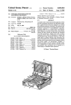
The RD-145T is a high-density multiplex peM data recorder utilizing helical scanning recording techniques
on standard DAT tape. The RD-145T data recorder provides improved features and benefits of two tape
speeds. up to 16 selectable number of data channels, expanded recording frequency band, improved phase
characteristics, high signal-to-noise-ratio, selectable recording time. and reduced physical size as compared
to existing data recorders. The RD-145T can also automatically record memo sound. time codes, counter
values. and data numbers (lD numbers) with the dedicated channels (wh ich are independent of the data
channels) and has a high-speed search function utilizing the data number (ID number). Measurement
accuracy is increased as a direct result of these features.
Despite it compact design, the RD- I 45T is designed to operate from multiple power sources. including 90
to 264 Vac input. I1 to 30 Vdc input. and an option al rechargeable battery. This capability to operate from
multiple power sources provides the RD-145T with maximum f1exibility for laboratory use and outdoor fjeld
use.
An option al GP-IB interface unit, GP-302, connected to the data recorder enables a host computer to control
data recorder functions, thereby facilitating automatic measurement. By utilizing x I (standard speed)
reproduction except eH 1-16 recording, and the optional MB-300 expanded memory board with the GP-302.
digital data can be stored into buffer memory and retrieved for processing.
The easy-lo-use DAT recording media are cassettes conforming to the DAT conference standards. The
recording method used by the RD-145T also conforms to the DAT standards.
- I
2. FEATURES
I) Two lape :;peeds
Recording and reproduct.ion will be made at a speed (x I) matching to the DAT specification or a speed
two times (x2) the DAT specification. In 4, 8 or 16 channel recording with the x2 speed mode selected,
recording frequency is extended 10 2 times the bandwidth obtained at x 1 speed. A tape recorded at the
x2 speed can be reproduced at the x 1 speed or a tape recorded at the x 1 speed can be reproduced at the
x2 speed.
2) Multi-chaOllels and wide band
The RD-145T allows record channel selection of 2, 4, 8 andl6 channel selection at the x 1 tape speed.
The record bandwidth is 20kHz for 2 channels, 10kHz for 4 channels, and 5kHz for 8 channels and 2.5
kHz for 16 channels. At the x2tape speed, RD-145T allows recording channel number selection of 4,8,
and 16 ehannels. The record bandwidth is 20kHz for 4 ehannels, 1OlVIz for 8 channels and 5 kHz for 16
channels.
3)
Digital input
CH I accepts analog inputs or 14 bit panillel digital inputs switched. The digital signals enter or output
through the multiconneetor on the re ar panel. This allows recording of 14 channel contact signals,
externally eonverted AID signals, ete., thus extending application fjelds of the data recording . .
4)
High-quality data (accuracy)
A desired input range ean be selected among four ranges. An ADC using the delta sigma method is used
for each channel. The 64-fold over-sampling digital filter provides the satisfactory anti-aliasing
characteristics. An octuple over-sampling digital filter is used for output. Using filters designed to suit
the purpose provides the following high-quality data. The signal -to-noise ratio is 75 dB. The frequency
characteristic f1atness is +0.5 dB, -I dB. The phase difference between channels is 2° or less (at same
input range).
5)
Small and compact
Thf dat~ recorder iso approximat,ely 306 mm ,,:ide x 128 mm high x 280 Olm deep (12 1/ 16 x 5', 16 x
12 '16 JIl.), and welghs approxllnately 7.5 kIlograms (16.5 Ibs). The data recorder is therefore very
portable.
6)
L.ong recording time
When a 120 tape (approximately 60 m) is used, data can be recorded continuously for two hours by x I
speed.
.
7) Three power supplies
The RD-145T operat~s on either ac input of90 to 264 volts, dc input of II to 30 volts, which are provided
~lormally, and an optlOnal rechargeable battery unil. The battery unit can be incorporated by mounting
It on the data recorder. The RD-145T can be used both indoors and outdoors.
8) Easy operation
The RD-145~ is designed s~ ~hat an operation button corresponds to one function as much as possible.
These operation buttons fac!lttate operations for recording on a site.
9) Memo sound channel
I~ a~dition t? the da ta ch~nn.els. a channel used only for voice recording and reproduction is provided.
SlIlce the mlcrophone bUllt tnto th~ data recorder is provided normally for recording, environmental
sounds can always be recorded dunng measuremenl.
- 2
10) Time code recording chan ne I
In addition to the data channels, a channelused only fm recording and reproduction of time codes is built
in. The year, month, day, hOUfS, minutes, and seconds of the built-in elock with perpetual calendar are
automatically recorded. Since the time code is always automatically recorded, it can be used to confirm
the recording time of measu~ement data on the display.
11) Data number (10 number) recording channel
In addition to the data channels, a channel used only for recording and reproduction ofiD numbers is built
in. The ID number of the recorded data is aUlomalically recorded. The ID number is incremented by one
each time recording starts or the EVENT button is pressed.
12) High-speed sem'ch
The recorded ID I1llmber can be searched for at high speed during reproduction. The search is perfonned
both in the forward and reverse directions. When the target ID number is found, the target data is
reproduced from the beginning.
13) Bar meIer monitor
All channels can be monilored al olle time with Ihe 6-segment display bar meIers. In Ihis case, the memo
sound channel can also be tnonitored. The signal level can be monitored both during recording and
reproduction.
14) Speaker monitor
The memo sound and the data of any data channel can be heard from the built-ill speaker.
15) RD se ries alld tape compatibility
Tape compatibility is established amollg RD-120T(TE), RD-130T(TE), RD-125T/RD-135T, RD-180T, and RD-200T as long as both the models use a common channel mode (MPX mode). (Except a certain type of code information). However, some fUllctiolls obtained with a tape recorded by RD-180T and RQ
200T ure not obtained with GP-302. No compatibility is obtained with digital audio tape recorders. - 3
3. PRECAUTIONS
3-1) Model and Standard Accessory Check
Check
(0
see that the unit is the olle you ordered.
See item 8 in tJJis manual for the list of standard
accessories.
3-2) Setting Envil'Onment
When using the RD-145T, consider environmental conditions such as temperalure, humidity, dust,
vibration, barometrie pressure, magnetie fields, and atmosphere. Please note the following:
a) When moving the data recorder or tape from a plaee of low temperature to a plaee of high lemperalure,
eondensation may form around the unit or tape. Wait at least 30 minutes after turning on the power
or after cheeking that there is no dew eondensation around the unit and lape before inserting a tape.
H a tape with cOlldensation is inserted, the tape may beeome tangled around the rotary head.
Condensation may form if the temperature varies 15°C (59°F) or more per hour irrespeetive of the
humidity being within the specified range.
Note: If the condensation sensor operates, all tape operation LEDs light and tape operation is disabled.
b) Remove the tape from the data recorder before turning off its power. Turning off the power wilh a tape
inserted may eause the tape to become tangled around the rotary head, if there is any condensation
before the power is turned on again.
If the tape beeomes tangled arOllOd the rOlary head, take the appropriate action in section 6 of this
manual.
3-3) Input Terminal
The I10 terminal of the data recorder is unhalanced. When the BNC connector cable supplied as an
accessory is connected to the 1/0 terminal of the unit, the outer side of the connector is connected to the
frame of the unit. The input impedance is 100 kQ, the maximum absolute input voltage is ±70 V, and the
output impedance is 75 Q.
When a signal is input 10 the output terminal, the output amplifier may be damaged.
3-4) Power Supply
j··j . :l.·li
~
.,
i{f ,lI ':,
.:}
The data recorder operates from ac input of 90 to 264 volts or from dc input of 1l to 30 volts . If apower
eable which is not supplied as an accessory is used, use one with a small resistance. Since the power supply
unit of the RD-145T uses a switching method, excessive current flows from the battery at power-on time.
Therefore, use the power suitable for this current.
When using the BU-41 battery unit, optional accessory, mount it securelyon the data recorder. Use the
optional BU-41-CH battery charger for charging the BU-41. When the dc power supply inc\uding the BU
41 battery unit is used in the RD-145T, automatically operates if the voltage drops below approximately
10.2 V, shutting off the power. In this case, turn the POWER switch to the C> position to prevent the battery from discharging. To use dc power again, charge the batlery so that the eorrec! dc power voltage is obtained and turn the power on.
Note: Under the low voltage proteclion circuil actuated onee, the unit does not operale if dc power is
connected with the power switch turned Lo the J position. In such a case, turn the power switch to
C> and then I .
- 4
3-5) Cassette Tape
a) Designated Tape
v=1
~
1.0 t-
... c.n
0
~
We designate DM 120 or DM60 rnanufaetured by Hitachi Maxell Co . Ltd . for the RD Series data
recorders. Tapes other than those designated rnay fail 10 reeonJ or reproduce. At worst they rnay cause
unexpected trouble to the unil.
the designated tapes are not available, contact uso
Ir
b) Tape Insertion
When inserting a tape casselte in the cassette cornpartrnent, before elosing the compartrnent, always
rnake sure that the tape easseHe is pushed in all way. Also, after ejecting a tape eassette, whicli may
cause the tape cassette to be pushed back a little, berore closing the eassette eompartment, push in the
tape casselte a1l the way.
c) Avoiding BOT (Beginning of Tape) and EOT (End of Tape)
Avoid lape parts near BOT or EOT to ensure recording. That's because ne ar BOT 01' EOT the
connection between the tape alld the reel irnprints the tape causing dropouts. Especia1ly avoid the last
two minutes of the tape where imprints may be severe .
When storing tapes, rewind them to BOT in order not to form imprints near BOT.
3-6) Mounting optional Accessories
Mount the optional accessories after checking the data recorder. Refer to each specification manual for mounting the option al accessories, GP-302 GPIB interface unit, BU
41 battery unit, and ERAO remote eontrol unit, ete. hll~
1~
i
~
1lJ!I!
~
~m
ill
- 5
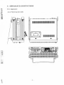
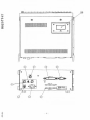
4. APPEARANCE AND FUNCTIONS
C\l
4-1) Appearance
~
lQ
4-1-1) Views from three sides
tO'J
,-4
o
0)
@@
f
f
.
......
•
. - i
I1- i
~
·,1'
1"-- 1
i ~\;~J
- 6
.
•
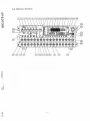
4-2) Reference Numbers
..
\
- 7
46
@
/'
/
@
/@
/
@
R( I[ T
@
51
50
~I ......
@
/
4-3) Names and Functions
Part No.
CD
®
Function
Name
REW button' LED
(Rewind)
-
- Pressing the REW button in the stop mode rewinds the tape.
Pressing the REW button once while in the FWD mode rewinds the tape
until the beginning of the data with the currently displayed ID number
at high speed then aUlomatically reproduees the tape.
In the same way, pressing the REW button more than once consecu
tively rewinds the tape at high speed to the beginning ofthe data having
lhe ID number less than that or the eurrent data by the number or times
the REW button is pressed minus one, then aUlomalicaJly reproduces
lhe tape.
(Note) When the ID number is recorded incorrectly, the above opera
tion may not be performed.
- When the REW and @ FWD buttons are pressed at the same time, the
data recorder enters the REVIEW (S-time speed tape running) mode.
No reproduction signal is output, however.
- LED Jights up in REW, REVIEW modes
F-FWD button' LED
(Fast-forward)
-
@
FWD button· LED
(Reproduction)
®
STOP button' LEI)
(LOAD STOP)
(UNLOAD STOP)
(Stop)
Press the F-FWD button in the stop mode to fast-forward the tape.
Pressing the F-FWD button once while in the FWD mode fast-forwards
the tape until the beginning of the data with the ID number next to the
currently displayed ID number at high speed then automatically repro
duces the tape.
In the same way, pressing the F-FWD button more than once consecu
tively fast-forwards the tape at high speed to the beginlling of the data
having the ID number greaterthan that ofthe current data by the number
oftimes the F-FWD button is pressed then automatically reproduces the
tape.
(Note) When the ID number is recorded incorrecily, the above opera
tion may not be performed.
When the F-FWD and @ FWD buttons are pressed at the same time, the
data recorder enters the CUE (S-time speed tape running) mode.
No reproduction signal is output, however.
LED lights up in CUE, F-FWD modes.
-
Pressing the FWD button while in the stop mode runs the tape in the
forward direction and reproduces the tape.
- Setting the ID number with the @Number buttons in the stop mode
then pressing the FWD button searches the tape for the set ID number
at high speed then automatically reproduces the tape.
(Note) When the ID number is recorded incorrectly, the above opera
tion may not be performed.
- LED JighlS up in FWD, REC FWD, CUE, REVIEW modes.
- Pressing lhe STOP button while in any mode stops the tape running or
releases the pause mode and LED Iights up.
- There are two stop modes:
LOAD STOP:
When the tape is touching the head
UNLOAD STOP: When the tape is not touching the head and the tape
has reaehed its end
(Note I) The data recorder enters the UNLOAD STOP mode after
approximately one and half minutes by x2 and 3 minutes by
x 1 tape speed elapse in the LOAD STOP mode.
The STOP LED alld 7-segmellt ID LEDs flash.
(Note 2) The UNLOAD STOP mode is for protectioll of the tape and
the head.
- 9
Part No.
Function
Name I--------~--------·--------- f---------------------------------------------------------
@
REC button· LED
(Recording)
@
PAUSE button· LED - Pressing the PAUSE button while in the REC or FWD mode pauses
(Pause)
recording or reproduction. Pressing the FWD button again resumes
recording or reproduction.
Pressing thePAUSE button while in the FWD mode causes the PAUSE
LED only 10 light
- Pressing the PAUSE button while in Ihe stop mode is equivalent to the
pausing while in the FWD mode.
(Note) The data recorder enters the stop mode after approximately one
and half minutes by x2 and 3 minutes by x I tape speed elapse
in the FWD PAUSE mode. It enters the UNLOAD STOP mode
after approximately one and half minutes by x2 and 3 minutes
by x I tape speed elapse.
- Pressing the REC button while in the stop mode lighls LED, causes the
REC and PAUSE indicators 10 light and prepares for recording. After
this, pressing the FWD button starts data recording.
(Note I) Pressing the REC and FWD buttons at the same time does not
start data recording.
(Note 2) The REC and PAUSE indicators flash and the da ta recorder
enters the UNLOAD mode after approximately one and half
minutes by x2 and 3 millUtes by x I tape speed elapse in the
REC PAUSE mode. Pressing the FWD button in this status
starts data recording.
(Note 3) When the user presses the FWD button with the REC and
PAUSE indicators flashing, the data recorder enters the REC
mode after a few seconds.
--------+----------------- r---------------------------------------------------------I
EJECT button
(Ejection)
- Pressing the EJECT button once while in a mode other than the REC and
REC PAUSE modes opens the @ cassette compartment, enabling the
tape to be inserted or removed.
(Note) Eject operations are valid only when thc-power is turned 01).
- - - . - - - -- -- - - - - - - - - - - - --/---- - - - - -- - - ------- -- - - --------------------- -- - - - -- -----I
@
MULTI DISPLA Y
(Bar graph/input
range display)
- The input ranges or bar meters selected by the ® B/R button are dis
played.
- In the top row, the monitor channel or the channel for which the input
range is to be switched is displayed .
- When the bar meters are selected, the 110 levels of all channels and
memo announcement are displayed. In the REC PAUSE or REC FWD
mode, the input levels are displayed . In the FWD mode, the reproduc
tion levels are displayed.
- When the input ranges are selected, the input ranges of all channels are
displayed with dots.
~ CH I bar meter does not light up when CHI is in digital input mode
(while LED @ is lighting) .
-------- - --_._-_.- ~ ------------------------
®
------------ -----.----- - - - --
B/R button· LED
(BAR/RANGE) - This is an alternate switch. This switch selects the input ranges or bar
meters for MULTI DISPLA Y. When the input ranges are selected, the
RANGE LED lights, Pressing the @ RANGE button switches the input
range of 1he channel selected with the ® CH SEL button. When the bar
meters are selected , the BAR LED lights. The bar meters are displayed
in MULTI DISPLAY so that the user can monitor the input status.
RANGE
- Pressing this button selects ±O.512/5120 Vp for the input level of the
chann el set with CH SEL. This operation is enabled only when RANGE
is selected with the ® B/R button.
- CH I range can not be set when CH I is in digital input mode.
- 10
Part No.
Name
Function
~----------------r-----------------------------------------------------i
@
CH SEL
- Selects the monitor channel. Specifies a channel for which the input
ra nge is to be set with RANGE. The LED corresponding to the
specified channel at the top of ® MULTI DISPLAY Iights.
- During STOP mode, pressing either one of CH SEL buttons and @
COUNTER MODE button at the same time for 3 seconds sets eH I
digital input mode and @) LED lights up. Pressing the buttons again
at the same time for 3 sec returns the mode to normal analog input
mode.
- With the _CH I digital input mode selected, the CH I can not be selected
as a monitor channel.
@
COUNTER
(Minutes/seconds
display)
- Displays the minutes and seconds which are recorded on the tape.
Alternatively, displays the minules and seconds which have been
recorded on the tape.
- The maximum display is 199 mihutes and 59 seconds.
(Note) lf a tape is used which has no counter value recorded in each
mode, nothing may be displayed.
l:'
~
tQ
I:
m
,....
0
~
~------~---------------~+------------------------------------------- .--------~
MODE SW button
(A-P mode switching)
- Switches the counter display between the ABS (Absolute) and PGM
(Program) modes.
- During STOP mode, pressing either one of @ CH SEL buttons and
MODE button si multaneously for 3 seconds, the unit enters CH 1 digital
input mode and @) LED lights up . Pressing the buttons again for 3 sec,
the unit returns to the normal analog input mode.
ABS (Absolute) LED
(Absolute time)
- When the LED lights, the absolute time from the beginning of the tape
(BOT) is di splayed on the @ COUNTER .
(Note I) The value displayed on the A counter <;Iisappears after a gap
between data when cJata is recorded discontinuously on a
tape or the data is reproduced.
(Note 2) When a program is recorded at a speed ofx2, a value oftwice
the recording time is recorded .
Beginning of tape (BOT) RECFWD
STOP
I A' mode
00000
~I
xxxxx
RECFWD
>I
I
A mode
No display - - - - - - - No display
I--------+----------------t-----~----------------------- .
PGM (Program) LED
(Program time)
STOP ---- -- - -- - - - - -·---- - - - ----1
- Wheli the LED lights, the time from the beginning of data (BOT) for
each ID lIumber is displayed on the @ COUNTER.
(Note) When a program is recorded at a speed of x2, a value of twice
the recordillg time is recorded.
ID=IO
10=01
REC FWD
STOP
~$7~~
~
>I
RECFWD
~ff#&
1
P mode
00000
.. I
P mode
xxxxx
- I1
STOP
00000
xxxxx
Part No.
Function
Name r-- ' @
ID
(Data numberdisplay)
-
Displays the data number. Displays the following in addition to the data number ID display -00 f1ashing
-
-
Status
Tape being loaded or unloaded
AA
Unrecorded tape
bb
On the lead-in tape for five seconds from BOT
No display
No tape
EE
On the E MARK
When the data recorder enters the REC PAUSE or REC FWD mode from
the begi nning of the tape, the tape automatically rurts with ID number bb
displayed for approximately five seconds. The data recorder then pauses
recording in the REC PAUSE mode or records ID numbers starting at 0 I
in the REC FWD mode.
When recording ID numbers on an unrecorded tape, numbering auto
matically starts at 0 I. An arbitrary number cannot be set.
In each REC FWD mode, the ID number is incremented by one before
it is recorded.
For nine seconds (x I speed) and 4.5 seconds (x2 speed) after the ID
number changes, the decimal point of each digit in the display flashes.
@
EVENT SW
- Pressing the EVENT switch button while in the REC FWD mode
increments the ID number by one.
- It takes about nine seconds (4.5 seconds at x2 speed) to record an ID
number. While recording the ID number, the EVENT switch button is
disabled.
@
CLOCK
(Clock/calendar
display)
-
Displays the time (hours, minutes, and seconds) or the calendar (year,
. month, and day).
Recorded tape
Displays the reproductioll time Oll the
tape.
Unrecorded tape
Nothing may be displayed .
FWD
F-FWD REW
STOP
PAUSE
Previous state
,
REC PAUSE
REC FWD
During power-on
~-
Displays the time in real time.
(Note) When the MPX ERR indicator lights or a tape which was
recorded incorrectly is reproduced, a hit-or-miss display may
occur or nothing may be displayed. This is not an error,
however.
--
@)
CALENDAR LED
- While the LED fights up, the year, month, and day are displayed on the
@CLOCK.
REAL TIME LED
(Clock real time indi··
cator)
-
~ ,
@) Whilc the LED lights up. hours, minutes, and seconds are displayed on
the@ CLOCK.
",
- 12
Function
Name Part No.
-------1---------------------~-------------------------------------1
®
~
~
LO t-
~
,.....
r---@
0
~
CLOCK SET
®)
- When the user presses the @ MODE SW button three or more seconds,
the 7-segment LED of the least significant digit in the CALENDAR
(year, month, and day) 01' REAL TIME (hours, minutes, anti seconds)
mode starts tlashing. Enter the year, month, and day or hours, minutes,
and seconds with the ®) number buttons from 0 to 9.
.
- Press the @ CLOCK button after entering the desired numbers with the
@ number buttons. Then the time setting is complete.
- Used ·to switch the @ CLOCK display between the CALENDAR (cal
MODESW
endar) and REAL TIME (clock) modes. LEDs @ or @ shows which_
(CALENDAR-REAL
mode is seleeted.
TIME mode selector
switch)
Number buttons
(I. 2 ..... 9. 0)
- Used to seareh a tape on which ID numbers are recorded for an ID or set
the ealendar clock.
----_._-------------------------------------------------~
@
- Generates a test signal of about 50% at 1 kHz.
TEST
(Test signal generator) - A test signal is output while the TEST button is held down in the REC
PAUSE 01' REC FWD mode.
- Can be used for checking the E-E (A/D --t DIA) function during re
eording 01' for a simplified check of the recordlreproduction functiOl'
du ring reproduction.
- With the CH I digital input mode selected, CH I cau not be inputted.
PLOCK
- When the ® LOCK indicator flashes, theu Jights by pressing the P
LOCK switch three or more seconds, all switches are locked.
- When the ® LOCK indicator flashes, then goes off by pressing the P
LOCK switch three or more seconds, the switches' are unlocked.
EMARK
- Prcssing Ihis button three or more seeonds in the REC PAUSE mode
writes an E mark.
(Note I) For details, see Section 5-11, "End Sem-ch" on page 25.
(Note 2) No recording can be performed on any E mark.
(Note 3) No E mark eall be writtell followillg an unreeorded portion or
in a range within ni ne seconds (4.5 seconds at x2 speed) from
an ID change.
1- - - -- - - - f--------~------ - - - - - -- - - - - - - - - - - - - - - - - - - - - - - - - - - - - - - - - - - - - - - - - - - - - - - - - - - 1
ESEARCH
(End sem'ch)
-
- Pressing this button performs REW, searches a tape for the end of
reeording 01' a recorded E mark from BOT at a high speed, and stops tape
running.
- Pressing this button three seeonds in the STOP mode performs the above
operation.
--- ----1------ - - - - - - - - - ----+- -- -- -- - - ------ - - - - - - - - - - - - - - - - - - - - - - - - - - - - - - - - - - - - - - - - - 1
MPX SELECT
button· LED
CHI-2
CHI-4
CHI-8
CHI-16
- Switches the number of channels used for recording. The LEDs for
recording light as folIows. This switeh is disabled during recording.
When this switch is set to CH I to 2, signals can be input to oroutput from
the first and second channels.
When the switeh is set 10 CH I to 4, signals ean be input to oroulput from
the first through fourth channe1s.
When the switeh is set to CH I to 8, signals can be input to or output from
the first thr~)Ugh eighth channels .
When Ihe swilch is seI 10 CH 1 to 16, signals can be input to or output
from the first Ihrough sixteelHh channels.
- 13
Part Ne.
Function
Name MPX REP ERROR
LED
(Data reproduction
error)
MPX REPRO LED
CHI-2
- Lights when a data error occurs in the REC FWD or FWD mode resulting from a damaged tape, recordi ng malfunction, reproduction malfunction, or clogged head . - Lights when a tape wh ich was recorded by the audio tape recorder such as audio R-DA T is reproduced.
(Note) This indicator lights when an unrecorded tape is reproduced.
The status of this indicator remains unchanged until the next
reproduction.
- MPX display during reproduction
- If two channels are selected during recording. the CH I to 2 indicator
alltomatically Iights in the FWD mode.
If four channels are selected dllring recording, the CHI-4 indicator
automatically Iights in the FWD mode.
If eight channels are selected during recording. the CH 1-8 indicator
automatical1y lights.
If sixteen channels are selected during recording, the CHl-16 indicator
automatically lights.
(Note) When tape containing no record is reproduced, alI indicators
light. Even when reproduction is completed, these Iights
remain on until the next reproduclion start.
CHI-4
CHI-8
CHI-16 - Shows recording speed ofa reproduced tape. x2 LED lights up automatically
when a tape recorded at x2 speed is used and xl LED lights up auto
matica lly when a tape recorded at x I speed is used.
(Note I) Reprodllction tape speed will be set with ® SPEED
SELECT.
(Nole 2) The display is nol defined during error display @.
(Note 3) The display is stored after completion of the reproduction.
SPEED LED
x2
xl
SPEED SELECT button· LED
x2 xl 7
Sets tape speed for recording and reproduction. The setting will be made
under STOP mode or no tape loaded. I---------t---------·- - ------- r-- ------- -- ---·------------------------------ ---- ----------I
Microphone SW
1----- - - --1-------- -- ---
- -- - - 1 - - -- - - --
Microphone hole
1----- - +--- - ----- -- -
®
LOCK LED
- When this switch is on with no external microphone connected . the
microphone built in the main unit is on.
- When Ihis switch is on with an external microphone connected. the
built-in microphone is off and the external microphone isoon regardless
of whether the press talk SW on the external microphone is on.
- When Ihis switch is off, the built-in microphone is off. The external
microphone operates depending on whether the press talk SW is on.
(Note) When an externalmicrophone is connected to Ihe optional ER
40 remote conlrol uni!, the setting of the built-in microphone
SW on the main unit does not work.
- - - - -- - - - - - - -- - - -- -_
_ __ _____________. _
_
- Hole for the built-in microphone
- - -- -- - -- --
- ----- - -----_ _ _ _____ ______ _ j
- Lights up in the panel lock status.
- 14
Part No.
Nam e Funetion
-
®> -- -
- Flas hes when the voltage is 11 Vor less when the de power or option al
battery lInit is llsed.
BATT ALM
(V 0 Itage aIarm
indieator)
--- -
-- -
®
~. _ - - --- - ---- - - --- - -- - -
-
MEMO IN
_._- _..-
®
- - -- - -
~~-
~
SPVOL
-- - -
®
-
-- -~-
-
-
-
- Usecl to heur the memo sound or duta sound from the earphone.
- When the earphone is plugged into the MEMO OUT jack, the sound
frorn the speaker is disconnected.
--- ----- Volume control of the speaker and the earphone.
MEMO OUT
(Earphone output)
-
@
- -"
Used when the memo sound is input with the mierophone supplied as an
aeeessory.
When the mierophonejaek is plugged into the MEMO IN eonneetor, the
built-illmicrophone is automatically diseonneeted and memo sound ean
be input via the externa! microphone only.
~
- ~--- ~
~- -- - -- - ~-
~-
- DATA/MEMO selection swi tch. Selects MEMO sound or DATAsound
and outputs it through a speaker or earphone.
DATA/MEMO
- - - _.
@
CHI/DIO LED
@
INPUT
(Input connec tor)
@
OUTPUT
(Output cOllnector)
.-
- -- ----
@
----_
MONI OUT
(Monitor output)
._
- Lights up when CH I is set to digital mode . The LED also lights up when
a tape reeorded with digital input mode is reproduced and the unit enters
the di g ital mode.
- CH I digital input mode is set by pressingeitheroneof@ CH SEL buttons
and @ COUNTER MODE button at the same time for more than 3 sec.
Pressing the buttons again at the same time for more than 3 sec releases
tbe digital input mode and returns the unit to the analog input mode.
- CH I of@ MULTI DISPLA Y does not light up when the LED is turned
on. Moreover, CH I can not be selected as a monitor channeJ.
- When the LED is turned on, CH I can not use the @ @ BNC IIO
connectors. Use @ DIGITAL 1/0 connector on the rear panel in this
case.
- Input connector
- The input voltage range is ±O.5 V, ±2 V, ±5 V, or ±20 V (maximum).
- CH I does not accept its input when the digital input is selected.
- Output connector
- The output leve l can be adjusted with ®> Volume control on the rear
panel.
- The output is not fed to CH I when @ CH I/DIO LED is lights up.
-
- -- - ~
- The output of the channe l sel ected by the channel selector switch is as
folIows:
Mode --_.- ----- - -- --
--
STOP
MON] OUT
- - --
- --
- -- - -
OV
FWD
J ape output
REC FWD
REC PAUSE
-------- ~- -
F-F WD
REW
- 15
E-E (A/D
~
D/A) output
- --_._-- - - --OV
._-
Part No.
Function
Name
@
POWER
(Power switch)
-
@
Rubber foot with
stand
- Pulling out the stand enables the front of the data recorder to incline
about 10'.
@
CASSETTE
COMPARTMENT
- Pocket for inserting and removing the tape
- Pressing the EJECT button when tbe power is supplied opens the
cassette compartment, enabling the tape to be inserted or removed .
- Push the casselte comparlment seeurely enough to close ancllock it.
@
REMOTE
- For use with the optional ER-40 remote control unit.
- Tbe switches Oll the dala recorder are operable even during use of the
ER-40 .
- The switches Oll the data recorder are valid wben both the switches on
the data recorder and the ER-40 are pressed at tbe same time.
@
DIGITAL 1/0
Connector
(D Sub 37P)
- Accepts digital input and outputs digital signal when CH 1 is in digital
input mode.
- Effective only when @ CHlIDIO LED is on.
@
I1F connector for
GP-302
- When optional GPIB Unit (GP-302) is used, the connector of GP-302
is cOllnected to this connector.
®
OUTPUT LEVEL
- Adjusts output voltage at the @ OUTPUT connector.
Adjllsted to develop 2 Vp at 100% input when the control is fully
turned in countcrclockwise direction.
- Max 5 Vp available.
®
Fuse holder
- Oll each holder, a fusc for ac or dc power is mountee! . I@ dc power input
connector
- Connected to the cable c\uring the use of e!c power. - Also connectee! to the connector of the option al B U -41 battery unit. i@ ac power input
connector
- Connected to the cable c\uring the usc of ac power. @
FG
(Frame Gronne!)
- Grounding terminal This is a rocker switch. Pressing the upper side ( I ) of this switch
turns on the power. Pressing the lower side (e» of this switch turns
off the power.
-
- 16
5. OPERATION METHOD
5-1) Basic Operation
Perform the following operations and checks according to the steps below:
Step
1) Connect the power cable.
Be sure to check whether the input power conforms to the specified
vo)(age .
2) Turn the power on.
Display of this unit
COUNTER
Off
ID
Off
CLOCK
Year, month , day or hour, minute and second display
MODE
CALENDAR or REAL TIME
1f the BATT ALM lights, increase the dc power-supply voltage.
3) Press the EJECT button.
The cassette compartment is opened. 00 flashes or is off. ID
•
4) Insert a cassette tape.
1
5) Press down the cassette
compartment.
t
6) Automatie tape loading
1
7) Press the REC button.
~ "(')
,
1
<Cl
')J .
8) Press the FWD button.
_. !
~;'l~' ~
Precautions and display of this unit
(
Approx . 60 seconds (Press the TEST
button .)
Insert a cassette tape so that the direction of its arrow matches that of the arrow on the cover of the cassette compartment. (J)se a new cassette tape starting at the beginning of the tape.) Always push the tape cassette into the cassette compartment all the way . Refcr to 3-5) "Casselte Tape" on page 5. Press the cassette compartment until it locks . After the tape is
COUNTER
ID
CLOCK
loaded automatically, it touches the head and runs a little.
Off
00
Calendar or time display
The REC and PAUSE indicators light. (Preparation for recording is
complete.)
ID
bb
REC
}
These indicators flash for about five seconds.
PAUSE
Recording starts the moment the REC and FWD indicators light.
COUNTER Recording elapsed time display (common to bolh ABS
and PGM modes)
(Note 1) The COUNTER shows a real time when a
recording is made at speed of xl. However, time is
counted at a rate of twice the real time when the
recording is made at speed of x2. That is, the counter
shows a time converted into a time equivalent to the
speed of xl.
lD
01 CLOCK
Calendar or time display When the TEST button is pressed. this unit records 1kHz and approx.)
50% test signal.
(
Bar meter: The last three dots are turned on for each channel. For
channel M (memo) ambiellt sound level is indicated.
Generation of the test signal stops when the TEST button is released.
- 17
Precautions and display of this unit
Step
9)
Press the PAUSE button.
1
10) Press the FWD button.
(
Approx.60
seconds
I I) Press the PAUSE button.
The tape stops running temporarily the moment the REC and PAUSE
indicators light.
COUNTER
Stops.
ID
01
CLOCK
Calendar or time display
Recording restarts the moment the REC and FWD indicators light.
COUNTER
ABS Displays continuously.
POM Elapsed recording time indication beginning with
000.
(Note I) The COUNTER shows a real time when a
recording is made at speed of x I. However,
time is counted at a rate of twice the real time
when the recording is made at speed of x2.
That is, the counter shows a time converted
into a time equivalent to the speed of x I.
ID
02
CLOCK
Calendar or time display
Conforms to step 9).
ID
02
I
I
03
I
I
Repeats recording
operation (approx. 60
seconds for each op
eration) in steps 8) and
9) unlil the ID number
reaches 10.
I
I
I
I
I
I
I
09
I
I
IO t
12) Press the STOP button.
1
13) Press the REW button.
The tape stöps running.
COUNTER
Stops.
]I)
IO
CLOCK
Calendar
01'
time display
The unit rewinds the tape to the beginning and stops automatically.
Operation during tape rewind:
COUNTER
Displays the counter value recorded in the tape.
ID
Displays the ID value recorded in the tape .
CLOCK
Calendar or time display
Whcn the tape is stopped:
COUNTER
Off
]I)
00
CLOCK
Calendar or time display
-]
~
.<
- 18
Step 14) Press the FWD button.
Preeautions and display of this unit
This unit reproduees the contents recorded from the beginning ofthe
tape.
COUNTER
ABS: Continuous minute and second display from 000 (begin
ning of tape)
(Note 2) A real time is displayed when a recording is made
at speed of x I. However, when a recording is
made at speed ofx2, the time is displayed as twice
the real time.
POM: Minute and second display from 000 whenever recording
starts.
(Note 2) A real time is displayed when a recording is made
at speed of x I. However, when a reeording is
made at speed of x2. the time is displayed as twice
the real time.
ID Displays 0 I to 10.
CLOCK
CALENDAR:
REAL TIME:
Displays the recorded year, month, and date.
Displays the reeorded hour, minute, and second.
Bar meter
Each ehannel:
M (memo) ehannel:
SP VOL: Displays the value of the recorded signal
Displays the level of the recorded ambient
sound.
DATA/MEMO selector switch enables the .
sound recorded in the memo channel or
data sound of the channel selected by CH
SEL ta be heard
MONIOUT
Outputs ~ata of the data channel selected by CH SEL.
MEMO OUT
The duta ean he listened to lIsing the earphone, in which ease the
speaker is diseonnected . .
- 19
5-2) Input Connections andl Tape Speed, CH MPX, and Setting of Input Range
Connectthe 1/0 cable supplied with the unit to the INPUT connector and connect a signal corresponding to euch channel cable. With the tape speed X I selected, RO-145T accepts inputs through CH I-CH2, CH I-CH4, CH l-CH8, CHl CH 16, and the chunnels can be switched wi th the MPX SELECT button (CH 1-2/CH 1-4, CH 1-8/CH 1-16). Recording frequency is OC to 20kHz. for each chal111el when CH 1-2 mode is selected, OC to 10kHz. when CH 1-4 mode is seleeted, OC to 5kHz. when CH 1-8 mode is selected and OC to 2.5kHz. when CH 1-16 mode is selected respeclively. With the tape speed X2 selecteel, RD-145T accepts signals through CH I-CH4, CH I-CH8 or CH I-CH 16, anel the recording frequency corresponding to above channels are OC to 20kHz., DC to 10kHz. or DC to 5kHz., respectively. Seleet the tape speed and CIl MPX according to your pUl-pose. Setting of tape speed
Set the tape speed with the SPEED SELECT button before loading a tape or in the STOP mode. The
selected tape speed is shown with a LED just upper the SPEED SELECT button. Recording or
reproduction will be made at the tape speed set.
Note: The speed settingis only enable in the STOP mode or no tape loaded.
Setting of CH MPX
Set a channel MPX with the MPX SELECT button. The conlent set is shown Oll a REC CH 1-2, REC
CH 1-4, REC CH 1-8, and REC CH 1-16 LEO.
Note: The setting can not be made in the REC FWD mode. The CH 1-2 cannot be set whenthe tape speed
is set to X2.
Input range setting
Select one ofO.5V, 2V, SV, and 20V RANGEs depending on an input signal voltage. Press B/R button
to set the RANGE mode (R side LED lights up) and then select a desired channel with the CH button
and CH display. Next, select a desired range O.5V, 2V, 5V, or 20V with the RANGE button. Select a
next channel with the CH button and then :-;elect a desired range in the same way.
After completion or the setting, change the display mode to the bar meter display (B side LEO lights
up) by pressing the B/R button. Press the REC button and check the input level under the REC PAUSE
condition. Each vaille fm the input RANGE is a ± maximum value. A voltage higher than this value will
cause signal saturation, so care will be necessary. Always set the range so that OVER (uppermost of
the bar meter) cloes not ~ ight up.
Note: The RANGE setting can be made during REC FWD.
5-3) Output Connection and Level Adjustment
The output connectors develop the input signals in the REC PAUSE anel REC FWD modes and the tape reproeluction signals in the FWD mode. Connect the connector to other eguipment lIsing the I/O cable supplied with the unit. Note: No output is available in a mode other than REC PAUSE, REC FWD, amI FWD. Output level aeljustment
The output level can be adjusted within a range of :t2Vpeak to ±5Vpeak with the OUTPUT LEVEL
control on the rear panel. Since a DC OUTPUT CAL signal is obtained in the STOP mode as in the
following CD and @ , it can be used for the output voltage adjustment or to check input level for olher
equiplllent.
CD
Press the TEST button and P LOCK button sil11ultaneously in the STOP mode and a OC voltage cor
responcling to + 100% input will be obtained.
@ Press the TEST button anel E MARK button silllultaneollsly in the STOP mode and a DC voltage cor
responcling to -100% in put will be obtained.
The output level has been adjusted to elevelop 2V peak when 100% input enters with the OUTPUT
LEVEL control turned in fully counter-clockwise direction until clicks are hemd.
- 20
5-4) Memo (Announcement) Recording or Reproduction
This unit is equipped with a built-in microphone, so that it always records its ambient sound automatically
when the user presses the REC and FWD buttons with the MIC ON/OFF switch on. The microphone
provides the AGC control facility so that recording can be made at an appropriate level. The bar meter at
mark M shows the input level of the microphone.
When recording sound using an external microphone, plug the external microphone into the MEMO IN
connector. The microphone picks up sound when the user presses the press talk switch. When the MIC
ON/OFF switch is on, the mierophone pieks up sound regardless of the status of the press talk switch. The
built-in microphone is disconnected automatically when an extern al microphone is used. When there is
no memo to be recorded, the MIC ON/OFF switch must be turned off.
The speaker is used to reproduce the sound. When the user plugs the earphone into the MEMO OUT
eonnector, the speaker is disconnected.
5-5) Data Sound Monitoring
The user can listen to the input sound or the output sound reproduced from the tape in this unit. When the DATA/MEMO switch is set to DATA, the current mode is changed to the data monitoring mode. Then, select a channel with the CH SEL switch. Monitoring the input sound is permitted during REC PAUSE or REC FWD. 5-6) ID Recording al1d Reproduction
a) An ID number is recorded aUlomatically when data recording is made. An arbitrary ID number cannot
be recorded, however.
b) When REC PAUSE (REC FWD) is performed at the beginning ofthe tape (BOT), it runs automatically
for about 5 seconds with the ID indieator f1ashing with bb.
c) When reeording is performed after automatie reeording at BOT ends, the ID number always begins
with 0 land is incremented by one at every recording operation unless the tape is advanced over
unrecorded tape during recording. (See Fig. I.)
d) If there is an unrecorded portion of tape du ring continuous recording, and the power is turned off, the
ID nllmber for the next recording is 0 I. (See Fig. 2.)
e) Pressing the EVENT switch on ce during continuous recording increments the ID number by one and
the nllmber is recorded. This eauses astart ID to be reeorded for approximately 9 seconds (x I tape
speed) and 4.5 seconds (x2 tape speed), during which the decimal point of each digit in the ID number
display f1ashes and the EVENT button cannot increment the ID /lumber.
(To enable anormal search operation to be performed record for approximately 60 seconds or more for
each ID.) (See Fig. I.)
f) The ID number ean be used as a search number for finding the start of each recording portion as weil
as a recording number or file number. For the ID number to be used as a seareh number, the recording
for that ID number must be approximately 60 seeonds or more and there must not be any unrecorded
portion on the tape. Ifthe reeording is short or discontinuous, the normal search may not be performed.
(See Fig. I.) .
g) When a recorded tape is used midway for recording, the unit reads and displays the ID nllmber of the
recorded portion. Recording then starts from the portion with the 10 number of [display value + I] after REC FWD is performed. (See Fig. 2.) h) When an attempt to continlle an ID number by eliminating the unrecorded portion as shown in Fig. 2,
rewind the tape, stop it just before the end of the portion with 10 number 12, and perform REC FWD.
- 21
BOT Data
Direction of tape
clIllllol
~
be -
1
ID number
1
1
bb ------- bb :01----------- 01:02 -----------02:03----
Mode REC PAUSE
1
1
1
Approx.
1
1
I
5 seeonds
1
Approx. 60 seconds : Approx. 60 seconds :
----;~~~
(REC FWD) (automatie)
REC FWD
~~.
REC FWD
1
t
~~
1
-
REC FWD
y
Each point is the same as pressing
either the STOP, PAUSE, or
EVENT buttons.
Fig.l
Direction of tape
)0
~I
~~
Unrecordedor
---'~CL..LL.L.L.L..~.L...LL..~L-'-'_reco_rded.-"--por_tion-----LLLL~~~
1
I
ID number------------12: - Unrecorcled portion
I
'01---·----------- 01 :02-----
I
: - 08 is displayed after
: a recorded portion is
: reproduced.
09 -- -- --- -- - - --- 09: 10 - - -- -
1
I
I
1
1
1
I
I
I
I
1
I
FWD
REC FWD --~~·1""0(c--- FFWD
1
Y
1
I
t
STUP
Fig.2
- 22
REC FWD
.'0(
I
I
Y
REC FWD
5-7) Re.:ording with the Counter
a) The counter value is displayed in minutes and seconds (M,S), and is recorded automatically when data
recording is made. Arbitrary counter values cannol be recorded.
b) When REC PAUSE (REC FWD) is performed at BOT, the tape runs automatically for approximately
5 seconds without any display. (Fig.3)
c) The ABS mode or the POM mode is used for displaying the counter.
d) A continuous counter value is recorded when continuous recording is made in the ABS mode. If
unrecorded tape is used. The counter ABS value disappears after continuous recording stops.
(Fig.3)
e) If a recorded tape is Ulsed to record dala, Ihis unit automalically reads Ihe counter value of the previous
recording and starts recordi ng the counter value following that value when the cassetle tape is loaded.
( Fig. 4)
f) The POM mode value is recorded beginning with 00000 whenever arecording is made or the ID number
is incremented by pressing the EVENT button.
g) When a recording is made at speed of x I, Ihe countervalue is recorded as a real time. However, when
the recording is made at speed of x2, a value of twice the real time is recorded. So, multiply 1/2 to the
time when reading the time in terms of x2 speed.
Direction of tape
Beginning of tape
(BOT)
Data eannot be
I reeorded duri ng
~tEis interval. -=+
>
I
~~:~::rd~~ COUNTER AßS
POM
No
No'
·
display---display: 000-----No
No
I
display---display' 000-----Approx.
REC PAUSE
(REC FWDj
•
5 seeonds
(automatie)
I
I
I
I
I '
I
I
I :
'
' I
,
,
,
]0 I~
r - - No display ---,
015: 000 ------ 015:
I
,
,
I
015, 016 ------ 031,
' I
-~,~
REC FWD
I
y
1000-------015' 000
=-->--~-
REC FWD,
y
-
-.
REC FWD ~:
->-,~
I
y
y
Each point is the same as pressing either the
STOP or PAUSE buttons.
Fig.3
Direction of tape
>
: (same ns W h e n ) : recordi'.l g slarts
XXX :XXX + l---XXX + 15:: XXX +
I
from lhe
I
I
POM --- -------mmm: recorded portion ZZZ :000-----------015: 000 --
COUNTER ABS -- ---- ---- NNN:
--+:+-+
I
- - REC FWD
I
-~+-- REC FWD
FWD
F·FWD
Fig.4
- 23
t
--->--:
t
I
16--
5-8) CLOCK Recording
a) The clock value is recmded automatically when data is recorded .
b) Adjusting the two-digit of the year, month, and day
Press the MODE button to turn the CALENDAR LED on. Press the CLOCK SET button three or more
seconds to put the recorder in the calendar adjustment mode. Enter the desired year, month, and day
with the number buttons, then press the CLOCK SET button again to set the year, month, and day.
c) Adjusting the two-digit of the hours (00 to 24), minutes, and seconds
Press the MODE button to turn the REAL TIME LED on. Press the CLOCK SET button three_QLill..on:
put the recorder in the time adjustment mode. Enter the desired hours, minutes, and seconds
with the number buttons, then press the CLOCK SET button again to set the hours, minutes, and
seconds.
~econdsto
5-9) Reproduction Tape Speed Setting
Reproduction tape speed can be set with the SPEED SELECT button regardless ofthe recording tape speed. So, data processing will be made at two times the recording speed or a recorded tape will be reproduced at a half speed of the recording. Recorded tape speed is displayed with the REPRO SPEED X2/X I LEDs. Select a tape speed according to your purpose. Note: SPEED SELECT is enable in the STOP and EJECT modes only. 5-10) Search Operation
a) This unit can perform high-speed search with an ID number.
b) To enable the unit to perform normal search operation, as shown in Fig.I, continuous recording must
have been made and one ID number must be recorded about 60 seconds or more.
c) When the desired ID number has been located, the unit automatically starts FWD reproduction.
d) When the PAUSE button is pressed during searching, the unit enters the PAUSE mode (not the FWD
mode), after finding beginning of the data.
- - ID 04
)
10(
ID 05
)0
I
0(
ID 06
)0
I-+---- ID 07
Search point for a desired ID
FWD direction search
Automatic FWD
reproduction
REV direction search
Fig. 5 Searching the tape for ID 05
Search method:
I) Enter the desired ID number (01 to 99) with the number buttons from 0 to 9 in the STOP mode. Press
the FWD button, and the tape is automatically advanced to the entered number al a high speed. When
the entered number is reached, the data recorder enters the FWD mode and the tape is reproduced.
When the PAUSE button is pressed during searching, the unit enters Ihe PAUSE mode after finding
top of the ]D number entered.
2) To perform a search during reproduction by pressing Ihe FWD button, press the F·FWD button or the
REW button while in the FWD mode. The unit searches the tape for the ID number of [display value
+ N) and enters the FWD reproduction mode when the F·FWD button is pressed N times. The unit searches the tape for the ID lIumber of [display value - (N - I)) and enters the FWD reproduction mode when the REW button is pressed N limes. - 24
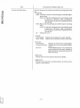
5-11) End Search (E SEARCH)
The E SEARCH button can be used to record data following a recorded portion on a tape.
(I) When no E mark is reeorded
Pressing the button searches for lhe end ofthe reeorded portion from BOT, and the tape stops running.
BOT
Unreeorded portion
~
Seareh direclion
t Search point
(2) When the E mark is recorded
Pressing the button searches for the E mark from BOT and the tape stops running immediately before
the E mark.
BOT EMARK
E~~~~~~~~~~~~~~~~~~~~~~~~~~Ju:';nr~e~e~o:r:d:ed~~
portion
. Record:d
,
-+- Search direction
portion
t Search point
In either ease shown above, when recording starts from the tape position after search operation, recording
continues from BOT.
(3) Use of E marks
Use the E mark to indicate the end of new recordi ng on a recorded tape. If more than one E mark is
reeorded on a tape, the tape is searched for first E mark from BOT. Record only one E mark on a tape.
5-12) Erasure
For the R-DAT cassette tape used in Ihis unit, previous reeordings are replaeed by new recordings when
a recording is made again on a recorded lape. Sinee previous recordings remain in the portions where
rerecording is not made, data, memo, 10, COUNTER, and CLOCK are reproduced. When these data items
interrupt data output or search operation, use the eassette tape whose entire contents are demagnetized by
a bulk tape eraser. Beeause the R-DAT eassette tape is very diffieult to erase, take enough time erasing
both sides of the tape with the bulk tape eraser.
If there are portions left unerased , they may eause meaningless numbers to appear in the COUNTER, 10,
and CLOCK displays and search or end search may operate abnormaIly.
- 25
5-13) Digital Channel Mode
C\l
CO
tQ
l:'-
OJ
The RD-145T allows seleelion of CH I in normal analog input mode or digital ehannel mode. In the digital
ehannel mode, digital signals in 14 bits parallel format ean be reeorded or reprodueed through a 37P muIti
conneetor on the rear panel, and the bit rate is equal to the sampling rate for the analog input.
Various status signals, externally eonverted A/D data, ete. ean be reeorded and reprodueed with analog
signals in other ehannels.
G)
Setting and releasing of the digital ehannel mode
,......
o
0",)
When STOP mode or no tape loaded, pressing eilher one of <IIC or ~ of eH seleet buttons and Ihe
COUNTER MODE button simultaneously for 3 see lights up the CH llDIO LED just side of the eH I
INPUT BNC eonneetor and the unit enters the digital ehannel mode. To return to the original analog
mode, press eilher one of CH seleet buttons ( ...., ~) and the COUNTER MODE button simultaneously
for 3 see again and the eH 1/010 LED Jights off and the unit enters the analog input mode.
When a tape reeorded with the digital channel mode is reprodueed in the FWD mode, the unit
automritically enters the digital ehannel mode and the data reprodueed is obtained at the 37P
multiconnector.
Note: • In the digital ehannel mode, the CH 1 bar meter does not light up. Moreover, setting of the
monitor selee! input range is not allowed for the eH I .
• When a tape reeorded with the analog input mode is reproduced in the digital ehannel mode,
the eH 1/010 LED lighls off and the eH I reproduees the analog signals.
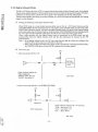
(2) 1/0 eircuit type
+5V
• Input eireuit type (DI 0 to 13)
lOK
~-------JVVV---~----4
100
Open eollector output, ete.
Olher equipment
VHOUT: More than 4"
VLOUT: Less than 1V
• Output circuit type (000
He 165
DATAIN
A-H
RD-145T
10
13, iN STB, OUT STB)
+5V
+5V
4.7K 51K
CMOS elc.
Open
VOH
VOL
IOL
Other equipment
eollector oulpul (wilh +5V pull-up)
: More than 3.5V
: Less than 1.1 V
: Max. 30mA
RD-145T
- 26
@
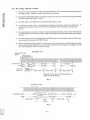
IIO timing spccificatio ns
• Input timing
DI 0 to DI 13
=><
I
X~~~~~~~X_DA_TA~--- - -
DA,TA
ts
I
th
I
:~:~:
L------Ir --
I
I
I
IN STB
~
~
_ _t_sa_n~lP~_ _-l~
ts: Sctup time: more than 50nsec
th: Hold time: more than 20nscc
Tape speed MPX
tsamp (flScc)
tstb (flSec)
x2 speed CH 1-4
x2 speed CH 1-8
20.83
5.2
41.67
5.2
x2 speed CHI-16
83.34
10.4
x 1 speed CHI-2
20.83
10.4
x 1 seed CH 1-4
41.67
10.4
x I speed CH 1-8
83.33
10.4
x 1 speed CHI-16
166.67
20.8
DATA
X
• Output timing
DO 0 to DO 13
-'
I
><
I
: - td
I
OUTSTB---
I
Istb
I:
I
I
r---
·1
tsamp
·1
td: DATA fixed after about 20nsec tstb, tsamp are same time as the input side. LaIch the DATA at fall ing edge of OUT STB. -~J -!
~
- 27
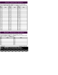
@ 1/0 connector signal table
Connector: Osub 37 pins, socket side
Signal name
Pin No.
Signal name
1
DIO
20
000
2
DI 1
21
001
3
DI2
22
002
4
DI3
23
003
5
DI4
24
004
DIS
25
005
DI6
26
006
DI7
27
007
DI8
28
008
DI9
29
009
DIIO
30
0010
DI 11
31
0011
DI 12
32
0012
14
DI 13
33
0013
15 IN STB 34
OUTSTB
16
OV 35
OV
17
OV 36
OV
18
OV 37
+5V
PinNo.
6
-
7
8
-
9
-
10
-
11
-
12
13
-
19
+SV
-
Note: +5V output allows maximum load of 100mA.
@ Analog channel and time relation
The digital channel data, which differs from analog channel data, are recorded and reproduced without
passing through anal(}g and digital filters, so, they are output at a fast timing when compared with those
in the analog channel. The time is as shown below.
X2 speed CH 1-4
approx. 1.7msec X2 speed CH 1-8
approx. 3.4msec X2 speed CHI-16 approx. 6.8msec XI speedCHI-2
approx. I. 7msec X 1 speed CH 1-4
approx. 3.4msec X I speed CH 1-8
approx. 6.8msec XI speed CHI-16 approx. 13.6msec Analog channel - - - - - - - - - 1
Digital channel - - - - - - I
,
'
---.--,-----;:---
,
- 28
I
,
I
I
6. MAINTENANCE
As a helical scanning rotary head is used in Ihis unit, the maintenance for this unit is a little different from
that 01' an analog recording data recorder. Read the following explanations and follow the maintenance
procedures.
6-1) Cleaning the Head before Recording
Berore recording is performed (once a day) or ifthe MPX ERROR indicator lights despile correet operation
during reproduetion cr if a waveform is missing, clean the rotary head by using the attached cleaning tape.
As soon as loading the cleaning tape, run it für about I () seconds with x I tape speed by pressing the FWO
button, then unload it. 00 nOl run the cleaning tape for longer than 10 secünds; otherwise the tape will
abrade the head.
The attached TZ-350H cleaner kit is used to clean the guides, pinch roller, and so on. 00 not wipe the rotary
head with the cleaning fluid, otherwise dirt will adhere to the head and around it, causing problems like
catching 01' the tape. eare must be taken.
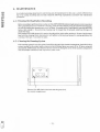
6-2) Cleaning the Running System
I f the running system is very dirty when viewed from the gap in lhe eassette compartment, clean the running
system (except for the rotary head) as shown in the following figure once every 20 to 30 hours using the
allached TZ-350H cleaner kit. Rernove the four screws for fixing the cover of the cassette eornpartrnent
with the Phillips screwdriver and wipe with a cotton swab.
®
c::;::::::""
~
10 01
®
®
I--
[
]
.
\
\
Remove four M2 plastic setscrews attaching the lid of
the casselle cornpartrnent.
I~
- 29
Do not wi pe the
rotary head with
the TZ-3S0H
cleaning fluid.
shaft
Tape guide
Guide pin
Pinch roller
Guide roller
Parts to be cleaned with the TZ-350H cleaning kit
(running-system parts whieh are visible when the eassette
eompartment is removed)
6-3) Action to Be Taken When the Tape is Caught by the Rotary Head
If the tape becomes tangled around the head due to condensation, immediately turn off the power and
eontact your neares! TEAC distributor. In ease of emergeney, take the following measure and eontaet a
TEAC service agency.
I) Turn off the power and disconnect the power cable.
2) Remove the setscrews (2 pcs. on top and 8 pes. on the rear panel) for the eassette compartment and slide
the top cover backward.
Top cover
M3 plastie screws 2 pes.
I'
DlOiTM. 110
* ~u::llJ::1:=_-==fL.ll6J:1I1
0
0
*
RIStT @
OU"'Uf UytL
@®®@(!)(!)@@~
I
•
1
:1
1011
4
!i
,
7
11
I~
."
I~ 1I~
•
1lO!J!LOJ!.i! · 14Sr:J
® ® ® ® (f) ®@ @QY ~. ~~7::A A"COADE~~
... ~_
_,............_ .....JI.(E_._ 3)
Loose the screws on the rotary head cover and remove it.
4)
Manually turn the rotary head eatching the tape about one turn clockwise.
5)
Leau out the slack tape with tweezers or a ball-point pen when the caught tape becomes slack. Lead
out more tape, turning the rotary head clocl<wise to unlangle the tape.
- 30
(.) Press down the lever in front of the cassette tape to open the cassette compartment.
Cassette tape
[L
n
Pul! the lever down.
7) Take out the cassette tape slowly and draw the tape into the cassette.
i==:::jrl-============~=;:==~(\
(3)
Open the cover.
(I) Press these convex
portions.
o o
(4) Rotate the reel to
wind the tape.
(2) Lower the cover.
8) Check whether any foreign material has adhered to the drum where the tape was tangled by turning
the rotary head slowly. Wipe off any foreign material with a cotton swab moistened with c1eaning
fluid of the TZ-350H cleaner kit. 00 not wipe the rotary head, however.
9) After cleaning, slowly wipe the surface of the drum with a dry cotton swab. Care must be taken to
prevent fragments of the cotton swab from adhering to the drum.
10) After the drum dries, turn on the power and allow 10 to 20 minutes for the unit to warm up.
11) Run the cleaning tape for about 10 seconds, then eject the cleaning tape, turn off the power, and install
the top cover and the lid of the cassette compartment.
Plastic screws are used to secure apart of the top cover and the cassette compartment cover, so they
will be damaged if too tightened. To prevent this tighten the screws with specified torque shown
below.
M3 plastic screws 2 pcs .................. 800g.cm • Top cover
M2 plastic screws 4 pcs .................. 350g. cm • Cassette compartment cover
12) Check that the unit is functioning properly by recording and reproducing with a new cassette tape.
Note:
• 00 not re-insert the damaged tape.
The tape may cause a problem because it is nearly worn out, a f10w is made on it, or dust adheres to
the rotary head.
• 00 not clean the heacl section with alcohol, cotton swab, ete. Always use the cleaning cassctte attachecl. - 31
7.
CON~FIGURATION Tape transport:
HEAD AMP PCBA
TTP I1F PCBA:
Servo, signal processing, error correction, control, etc.
I
CONTROL (I) PCBA:
CONTROL (2) PCBA:
I
ADIDA PCBA:
2
Front panel assembly:
Power supply unit:
Chassis:
8. STANDARD ACCESSORIES
R-DAT cassette tape:
BNC cable:
Connector 37P (digital 110)
Connector cover
Siotted screw driver
ac power cable:
dc power cable:
Microphone:
Earphone:
R-DAT cleaning tape:
Cleaner kit:
Fuse (2A for ac, 6.3A for dc):
Vinyl bag for accessory storage:
Caution label:
Instruction Manual:
33
1 für each
I
- 32
9. OPTIONS 9-1) Rechargeable Battery Unit BU-41
Baltery capacily:
Recordi ng li me:
Charging method:
Protect functioll:
Installation method:
Weight:
Dimensions:
12 V 6.5 Ah/20 HR Apprüx. one hüur continllollsly (when fully charged at the room temperature) The charge function is provided für in the power supply of this unit. Overdischarge protective fllllction (provided 1'01' in the power supply unit) Circllit breaker for protection ugainst overcurrent Inslalled with screws al the rear of the recorder. Approx. 2.6 kg (5.7 Ibs) Approx. 240 (W) x 109 (H) x 75 (0) mm (9 7 / 16 x 4 5 / 16 x 2 15 / 16 in.) (excluding .prolrusions)
9-2) Battery Charger BU-41CH
Available battel-Y:
Charging time:
Power requirements:
Dimensions:
Dedicated to the BU-41 (BUAO is also available) Approx. three hours (Two units can be chargedin parallel.) 90 to 130 Vac or 18010264 Vac Approx. 190 (W) x 90 eH) x 270 (0) mm (71/ 2 x 39 / 16 x 10 5 / 8 in.) (excluding protrusions)
9-3) Remote Control UnH ER-40
Control:
Microphone:
10:
Power supply check:
C:!ble length:
Weight:
Dimensions:
REW, F-FWD, PAUSE, FWD, STOP, and REC push-button switches
(Note) Tape speed switching function is not provided.
A microphone input connector and LOCK feature or the Illicrophone press talk
switch are provided.
The EVENT switch is provided. A low voltage indiculOr is provided for when the unit is used with dc power. Approx.5 m (16,4 ft) Approx . 550 g (1.21 Ibs) Approx. 165 (W) x 55 (H) x 64 (0) mm (6 1/ 2 x 2 3/ 16 x 2 1/2 in.) (excluding protrusiolls)
9-4) Fixed Handle for Vehicle TZ-701
9-S) Rack-mount Adapto.' TZ·70S RME/RMJ
9-6) GPIB Interface Unit GP-302
Power requireillents:
Functions:
Weight:
Dimensions:
90 to 250 Vac, approx. 20V t\ Transport control and retrieval (Note) Tape speed switching fllnction is not provided. Approx. 3.5 kg (7.7 Ibs) (includillg MB-300) Approx. 306 (W) x 48 (H) x 377 (0) mm (12 1/ 16 x 17 /8 x 14 13 / 16 in.) (excluding protrusions)
9-7) Memory Board MB-300
Installation method:
Memory capacity:
l N()t~ I)
lNlll~2)
J.·.
ril
, .l. .'
~
"
,:
Built in thc GP-302 3M bytes Not us~u in reproctuction mod~ at tape spe~d x2. use at tape speed x I. Dat:! transfer is impossihle when useu recorued lape by CHI-16mode. - 33
10. SPECIFICATIONS
10-1) Major Specifications
Recording and reproduction method: Tape used: Analog input and output system by multirlexing PCM recording and
reprodllctioll
DAT standard tape
Hitachi Maxell tapes are designated.
DM 120
lape lenglh: 60 m
tape widlh: 3.81 mm
DM60
tape length: 30 ll1
tape width: 3.81 Olm
Note: Refer to 3-5) "Cassette Tape" on page 5.
Conforms to the helical scanning R-DAT format.
16
High-order 14 bits of qllantization bits
Recording formaL: Number of quantization b its: Recording data lenglh: Head Recording and reproduction: 4 heads:
(Erasure):
Error correction method:
Tape speed:
Bead rotation al speed:
Recording time:
Start or stop time:
Fast-forward or rewind time:
2-head azimuth system (for recording)
2-head azimuth system (for reproduction)
(Erasure method by overwriting)
Double-encoded Reed-Solomon Code System
xl: 8.15 mm/s, x2: 16.3 mm/s (during recording or reproduction) x I: 2000 rpm, x2: 4000 rpm (during recording and reproduction) xl: 2 hOllrs, x2: I hour (during continuous recording with a 60-m tape (DM-120) x I: I hour, x2: 30 minutes (during continllous recording with a 30-m tape (DM-60)) Approx. 2 seconds Approx. 60 seconds (for a 60-m tape (DM-120)) 10-2) 1/0 Specifications (Analog Channel)
Input voltage:
Input impedance:
Input filters:
Output voltage:
Output impedance:
±0.5 Vp, ±2 Vp, ±5 Vp, ±20 Vp max. 100 kD. unbalanced (nominal) Both an analog filter and a 64-fold over-sampling digital filter are used. ±2 Vp to ±5 Vp (load resislance 100 kD. or more) 75 D. (nominal) Number of data channels and recording and reprodllclion frequency:
~1
~I
'.-:I
:"0; I
Tape Speed
xl (8.15mm/s)
x2 (16.3 mm/s)
Number of dala channeIs
2, 4, 8
4, 8 or 16 (changeover)
Sampling rate
48 kHz/24 kHz/l2 kHz/6 kHz
48 kHzl24 kHz/l2 kHz
Rccording and reproduclion
frequency
dc to 20 kHzldc to I () kHz/
dc to 5 kHzldc to 2.5 kHz
dc 1020 kHz/dc to 10 kllz/
dClo5kHz
01'
16 (changeover)
Note: Speed conversion will be made in the record allli reproduce mode. However, tape recorded
in the data 2 channel m()de at speed 01" 8.15 Illlll/sec cnn not be reproduced at x2 (16.3
111m/sec) speed.
' ~1
..\
1.~,; \
~J
'~1
l-;;:..!l
;,'r1:l
{:~m
~_.
- 34
Frt'qlll'ncy characlerist.ie (lai:
Output lilter:
....-4
t-
SN r;11.ioo:
1O
Phase dil'l(mmce between:
Cbamwls(skew):
t
C»
.-fJ
o
~
+0.6 dll, -1 d13 80th a octullic ovpr-sampbng digital Glter and a low pnss Jilter me used. 7&1B (Within the bamlwidlh) 2° or less (at same input I'nnge) 0.28 J.1 s(for 20k Hz) (;11, same i npu I, r;mge)
0.56 J.1 s(/or IOkJlz) (at same input range)
1.1 J.1 sOor 5kJ Iz) (at sanw ulpul range)
2.2 J.1 s(lor 2.5kHz) (at same input range) Crosstalk:
-7&lB (Within the bamlwidth) Linearity:
Dislor1.ion:
Drift:
±o.1 n;" 0.1 n;"
±O.I% or less (after 10 millutes 01' heat run)
10-3) Digital Channel (Analog ehanne1 CHI is swilcbed)
Input level:
Output level:
Rec/reproduce bit:
Transfer speed:
CMOSlevcl
OpEm collcetnr outlJUt (pnll-up 10 +5V)
14 bit parallel
E(l ual 10 sampling rate of analog channel
Syne lock:
Yes
Note: When the digital channel is sclccted,CHl analog enn not be rceorcle(Vreproduced.
10-4) Operating Conchl,ions
Opera6ng temperatuw: Rela1.ive InunidilY tluring: Opera1.ion: Vibration: Shock: ..q.:
r-'
rf I
tl
oDe 10400e (:32 F to 101 F)
0
0
20%, 1080"10 (non·mnc1ensing)
C'A:mlormstoMlI.rSTD-810CTABLE 514,2-VI V curve
Conlarms 10 MIL.. STD-81OC :30g-11 ms
10 ..[»FunctionaJ Specilicatioos
'Yl
Memo sound:
(Aulomatie rrx:ording)
eh:l<:
(Autol1lilt.ic nx:onling)
J1ecording reproducl.ion band. t!CXll]z 10 2(}(Xl!-lz
n,('cording wilh I.he builf:-in rn icrophOl1l'(wi1J1 I.ho ON/OFF
swilch) or an pxtcr!1al micl'ophone
I{ccorcling rcproduc1:ion ol'ycilr. !llolJl.h, day: hour. minute.
;]JHI sccond daln
Uisplay chnngpovcr syst.em ypar. mon I.h. nnd day:
(c:"(~ndar) or Iwur, minule. :md sccond: (rc~al tinlt')
IU nlllll[x'l'fi ()] to DU aw rn:onled or rl~prodl1c('d :md :np displ:1Y(,(1.
11) nUllllx~r: Illcn'lIwn I(~( I I>y ] (~vcI'Y rccon ling 01' wlwncver
or
IU (dai<! I1l1ll1lx'I'):
(J\ulolll:llic In:o\'(ling)
switch is pn~sf'l.'d durillg nx:onling.
bi:lnk f'I.':ln:h
11 igh-sll('('d f'I.':lrch oLl\l 1J) 11111111)(,1'
F-I.'WI). Imw I"WD. S'I'( lP. J{]';(:. I)!\USI'~. ;Ind 1'~.mCT
'1'111'
I'~ ((,l1d) f'I."tn:h:
S,':m'h:
( ;ol1lrol:
I';VI'~N'I'
I'~ (('lld) fl1:lrk o!'
Illlfih-IJllt IOllfi
!V1olli l(ll':
11:11' IIH'I('I' (:t11
d:ll:I Ch:llllH>/S;llId :II1H'll1oclwnlH'l)
SJl(~;t1\(,I'I<':lrphIllH'
!V1ollilol'
'n'fit fiigll; d:
(monilor l-'('l('l·t ('h:II1IH'll1H'I1H) cl1:\I1I1('I)
1iN(; ('()f1fH'c!OI' (monilor f'I.·II'I'1
('11:1I1IH'1)
I kl LI. :ll1d :lJlJlmx. !JUI;, l'tdl"l-'(';I]" sigl1;d hllill-il1
10-6) Others
Power system: Supply voltage (for ae/de): Current eonsumption:
Dimensions (W x H x D):
Weight:
~\ Switehing regulator system
Usable voltage and frequeney (The values in parenthesis are rated
values.)
9010264 (100 to 240) Vae
48 10440 (50 to 60) Hz
11 to 30 (12 to 28) Vdc
Automatie ae/de ehangeover (ac precedes dc, however)
The LOW BATT alarm funetion operates at approx. 11 Vdc or less.
Output is cut off at approx. 10.2 Vdc or less. (Overdischarge protection
function)
Approx. 0.85 A with 100 Vac
Approx. 3 . 6 A with 12 Vdc
Approx. 306 x 128 x 280 mm (121/16x 5 1116 x 11 in.)
(excluding protrusions)
Approx. 7.5 kg (16.5 (bs)
- 36
10-7) External View
Dimensions
':l3( 15,
I- - -~
t
0
~
-fR
280 (11)
~t--
-
~
=
=
=
=
=
=
=
=
=
=
=
=
=
=
=
=
=
=
=
=
=
=
=
=
=
=
=
=
=
=
=
=
=
=
=
=
=
=
=
=
=
=
=
=
=
=
=
=
=
=
=
=
=
=
=
=
=
=
=
"
•
~
~
~
~
=
=
~
~
~
N
~
·0
0
~
tt
•
~
~
b
~
~
~
0
~:
.Iijj p
•
~
'-C
0
<'")
Ci)
Cf)
-li: ~ :
~s:e
~
~
=
0
~p,pe
,I
e e
eCf) eG)
'0'0 P
•• ~p,-,
'-'
-'I'-'I°v·.
•
~'F G) G)
L.Ot..-........
n
U I- ,
I. ~ /10
e e
~. ~ ::: ~ e
a. IIOdO
~. ~ 0 1
I: ~ 0'0
Cf)
e e·
."0 '-" '-"
I·'- ::: 10!.O e'-' Cf) l..trn
\:I'
'"'
4==-:::::r=:;:/
r-
• I..
~
1"
0
• •
' --I
, "''' j
: ~J
'Y' :
~ ;
'Y.> :
;"
. ..\" .
-
I
1"J
' _.':~ 1
L
.~
------
E
E
--_.'-
- 37
f;.lv~~~m~a5§ (Information Products)
• ~tJlljFflT'-$7l/::J-::):I'(Data Recorders) .~~m§.~y~~~a@~~.~
(Sensors&Jl.mplifiers)
• ::J':::::::J..=7-Y3Yl/::J-::):I' (Communications Recorders) .*g ;rT-{ :;'$7J\;titt~T- -:1§[,'~~~
(Mass Storage Products)
• r:::'7':tT--:10::J-$i'(Video Tape Recorders)
• r:::'T>tT'-1::Z:7l/::J-::):I'(Video Disk Recorders)
.FA~~~
JiSJ;l1~~~m~Iffi§(Computer Peripheral Products}
• 7D'Yt:'-T'-{::Z:7~5-{7'(FIoppy Disk Drives) .CD-ROM~5-{7'(CD-ROM Drives) .7'-1:;'$7 J[;titt~T- -:1~c'~~~ (Tape Streamers) tO) {iliOYT ..{ 7'Y? ~fifl (Olher Producls) . ) \-~TJV::JYt:'::::J.. -$7~~~~ • :t-7~'-1:t&r:::·:::')'::::J..PJ[;~~~ (Audio&Visual Products) .I~m~~~ T -( 7'~ -7 ~* 50\; ~ 1± 1'180
~)';Ujllfi.t~~ mcpIHJ3 -7-3 l!l:i&',I;::lJ.!lgQ;tJrc~l. \t5bttlJ'"
~f-~i~~~gß
~
~3
(0422)52-5010, 5012 (04 2 2 ) 52 - 1 390 mJ;ll~~m1iMjß ~
~3
(0422)52-5046, 5047 I~ pg g; §iii i15 FAX
(0422)55-2582 Si:' Jnll :±l 5~ f'fT l' 300 ± JIHn i;IHIUT 11 -5 Llpt;: t:.)
~
~3
( 0 298) 2 4 - 2 865 ({t)
FAX
(0298)24-2866
~I c'J ~ g; ~ M 1'465 :g c'J ~ m:g
lZJ:tt 5-406 ~
~3
( 052) 702 - 235 1 (it) FAX
(052)702-3107 7; Il& '8 ~ r:fT l' 564 llX I±l m
71< IHJ 3 - 3 4 - 1 0 ~
~3
( 0 6 ) 3 8 4 - 6 0 4 1 ({t) FAX
(06)385-8849 0:-; ,~ g;
[3fT l' 730 11. !;~Hn cp [2; it§ JlI [J IllJ 1 3 - 1 9 ~
B3
(082) 294 - 4 7 51 ({t) FAX
(082)2944669 lffi f5l1 g; ~ rlT T 812 I!H'il] m 11'1 cg, [5Z SR 7{; 2 - 2 - 24 ~
~2i
( 0 9 2 ) 4 4 1 - 3 6 0 0 (i\';) FAX
(092)472-7 602 'liHR~~
DIV FAX
u
*-
m
*'
i~Il!lI~lMlg:Q;t.3~~\" \t?;bttl;j:···
m7g~m .M
~-~~M
~-~~2a
Cß ~~~
(0 4 2 2 )5 2 -5 0 6 8
/Ii! il11ilH!,§ "j}iitt1[1 §iiiJMII ']-{-)Wl:J')=-TIJ ::;:1:1)u-} 'Itl
t3ckU Uö},;~r:fT,
E,3
( 0 4 2 2 )5 2 -5 0 6 9
il.ß~prr
Head Office: TEAC CORPORATION 3-7-3 Naka-cho, Musashino, Tokyo, 180, Japan
ELECTRONICS AND INFORMATION PRODUCTS DIVISION
Tel:(0422)52-5016,5014 Fax:(0422)52-1990
U.S.A.:
TEAC AMERICA, INC, 7733, Teleyraph noad, Montebello, California 90640, U.SA Tel:(213)726-0303 Fax:(213)727-7621 CANADA:
TEAC CANADA LTD. 340 Brunel Road, Mississauga Ontario L4Z 2C2 Tel:(416)B90-8008 Fax:(416)890-9888 Germany:
TEAC DEUTSCHLAND GmbH.
Bahnstrasse 12, D65205 Wiesbaden-Erbenheim, Germany
Tel:06" -7'580 Fax:0611-715811
P/N 1003134800
RD-145T
DAT DATA RECORDER
ACCESSORIES AND SPARES
R-DAT Cassette Tape DH120
R-DAT Cleaning Tape
Cleaner Kit TZ-350H
Input/Output Cable
Hicrophon e
Earphone
Vinyl Case
Vinyl Cover
Power Cable (AC)
Power Cable (DC) CL - 53
Fuse De (6.3A)
Fuse'AC (2A)
14800108
14800128
17930220-02
15922849-00
15990450-00
15990330
10990910-00
10992242-00
Dri ver
15922282
15922836-00
E0036730
13297185
10023175-00
13124825
16362968
16910032
Instruction Manual
10111431-10
Caution Label
Connector37P
Cover Connector 37P
P/N.I0031708-01 1
33
1 copy