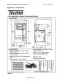
1
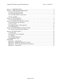
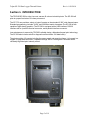
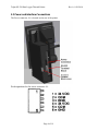
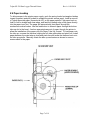
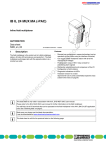
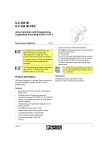
Telpar SP-328 Data Logger Thermal Printer
Rev A 8-26-2010
TELPAR
SP-328 Data Logger Thermal Printer
USER MANUAL
For Sales, Technical Support, Warranty Returns and Repairs, please contact us at
1-800-533-0904
Please visit our website at any time at
www.telpar.com
Page 1 of 19
Telpar SP-328 Data Logger Thermal Printer
Rev A 8-26-2010
Section 1. INTRODUCTION.....................................................................................................3
Section 2. OPERATOR INFORMATION..................................................................................4
2.1 Printer Front Panel Layout.................................................................................................4
2.2 Unpacking and Inspection .................................................................................................5
2.3 Power and Interface Connections.......................................................................................6
2.4 Paper Loading ...................................................................................................................7
Section 3. INSTALLATION .......................................................................................................8
3.1 Power Up and Self Test .....................................................................................................8
Section 4. INTERFACE SPECIFICATIONS ..............................................................................9
4.1 Serial Interface Specifications ...........................................................................................9
4.3 Flow Control ...................................................................................................................10
4.3 Parallel Interface Cable (Optional) ..................................................................................11
4.4 Parallel Interface .............................................................................................................12
Section 5. PROGRAMMING INFORMATION........................................................................13
5.1 Control Codes and Escape Sequences..............................................................................13
Section 6. MAINTENANCE.....................................................................................................14
6.1 Introduction.....................................................................................................................14
6.2 Required Tools and Supplies ...........................................................................................14
6.3 Cleaning..........................................................................................................................14
6.4 Printing Malfunctions......................................................................................................14
6.5 Maintenance Chart ..........................................................................................................15
APPENDIX ..............................................................................................................................16
Appendix A - ASCII Codes...................................................................................................16
Appendix B - PRINTER SPECIFICATIONS ........................................................................17
Appendic C - MCTF for thermal printer mechanism .............................................................18
Appendix D – Dimensions ....................................................................................................19
Page 2 of 19
Telpar SP-328 Data Logger Thermal Printer
Rev A 8-26-2010
Section 1. INTRODUCTION
The TELPAR SP·328 is a fast, low cost, narrow 40 column industrial printer. The SP-328 will
print at a paper feed rate of 2 inches per second.
The SP-328 can provide a variety of output formats on the standard 2.350" wide thermal paper.
Standard programming includes 11X28, and 22X28 dot matrix characters The SP-328 is also
capable of high density graphics. The SP-328 is equipped with a USB interface, RS-232
interface with a 4 position terminal connector, and a parallel interface connector.
Low maintenance is assured by TELPAR's reliable design, ribbonless thermal print technology.
The SP·328 also includes a built-in diagnostic self test and a 31K data buffer).
The printer weighs 4.5 pounds including the paper supply and mounting frame. It is housed in a
rugged 16 gage steel enclosure. It operates through -40 to +140 degrees Fahrenheit with a
constantly regulated print intensity control.
Page 3 of 19
Telpar SP-328 Data Logger Thermal Printer
Section 2. OPERATOR INFORMATION
2.1 Printer Front Panel Layout
Page 4 of 19
Rev A 8-26-2010
Telpar SP-328 Data Logger Thermal Printer
Rev A 8-26-2010
2.2 Unpacking and Inspection
Carefully unpack and inspect your SP-328 for any damage which may have occurred in transit.
Should any damage have occurred, notify Telpar. Specify the nature and extent of the damage.
Before installing or operating the printer, check the following:
1. Ensure that the primary power setting is correct for your installation.
2. Ensure that the printer mechanism and paper path are clear of all packing materials
and any other foreign matter.
3. Ensure that paper is installed. D0 NOT OPERATE the printer without paper. Refer to
Section 2.4 for paper loading instructions.
Page 5 of 19
Telpar SP-328 Data Logger Thermal Printer
2.3 Power and Interface Connections
The Power connector, J6, is located on the rear of the printer.
Pin designations for the power connector J6:
Page 6 of 19
Rev A 8-26-2010
Telpar SP-328 Data Logger Thermal Printer
Rev A 8-26-2010
2.4 Paper Loading
To allow access to the printer paper supply, push the spring loaded rectangular latches
inward (together) and pull forward to release the printer access panel. Install a new roll
of Telpar approved paper (thermal side UP) on the paper spindle. Fold paper back on
itself to form a straight and clean edge, and feed the leading edge of the paper directly
into the paper input slot. The paper will automatically feed paper through the
mechanism several inches. Use the feed button to advance paper through the bottom
take-up slot in the bezel - feed an appropriate amount of paper through the printer to
allow the installation of the paper onto the Paper Take Up Journal. To load paper onto
the take up, unscrew the fastener holding the left side guide plate and pinch rod. Install
paper between the main take up shaft and pinch bar and screw the fastener back onto
the take up spindle. Manually rotate the take up mechanism as shown to remove
excess slack in the paper.
Page 7 of 19
Telpar SP-328 Data Logger Thermal Printer
Rev A 8-26-2010
Section 3. INSTALLATION
3.1 Power Up and Self Test
The operating controls of the SP-328 have been kept to a minimum. A convenient self-test
feature allows the operator to quickly determine that the printer is operating correctly.
To activate the self test feature hold the feed button while switching the power switch from the
off position to the on position. After one beep release the feed button. The self test will begin.
The SP-328 enters self test mode and prints out self test page which includes a graphics
pattern, configuration information, and character tables.
For the highest quality output and maximum thermal headlife, it is recommended that only
Telpar qualified thermal paper is used.
TELPAR SP-328 Thermal Paper Part #: 751328-0030 (3 inch diameter roll)
Page 8 of 19
Telpar SP-328 Data Logger Thermal Printer
Rev A 8-26-2010
Section 4. INTERFACE SPECIFICATIONS
4.1 Serial Interface Specifications
The SP-328 can be used as either a serial or parallel device without requiring any switch or
jumper settings. The SP-328 will automatically detect the interface which is sending data and
produce the appropriate printout. The serial Interface parameters are factory set internal to the
printer firmware. Serial interface parameters must be specified prior to shipment. The standard
factory setting for the RS-232 serial interface is 9600 Baud, No Parity, 8 Data Bits, 1 Stop Bits.
RS-232 Terminal Connector Serial Interface:
Pin
Signal
Description
1
TXD
Data Output from the printer to the host.
2
RXD
Data Input to the printer.
3
GROUND Signal ground
4
BUSY
-10V when printer is unable to receive data.
There are two conventions used in the RS-232C interface; these are Data Terminal Equipment
(DTE) and Data Communications Equipment (DCE). Examples of DCE are modems,
multiplexers, and telephone data line interfaces. All other equipment which originates or
receives data such as terminals (including the SP-328) or computers is DTE. If two pieces of
DTE are to be interconnected it is necessary to transpose TXD and RXD as well as DTR and
CTS in the cable. This type of cable is called a null modem cable and must be used if the SP328 is to be connected to a host computer's serial port.
Page 9 of 19
Telpar SP-328 Data Logger Thermal Printer
Rev A 8-26-2010
4.3 Flow Control
The SP-328 employs a 31 K byte data buffer to allow the host computer to rapidly transfer data.
Under some circumstances it may be possible to completely fill the buffer. When the buffer is
within 50 bytes of being full, the SP-328 signals the host computer to pause until a line of data is
printed, or until the buffer is under the 50 byte limit The flow control information is sent to the
host using hardware and software protocols.
The hardware protocol uses the BUSY line of the parallel interface and the BUSY line of the
serial interface. These pins are asserted or negated as necessary to turn off and turn on the
flow of data. There is an optional (factory set internal to the printer firmware) software protocol
for RS-232 serial which uses the XON and XOFF ASCII characters (^Q and ^S) which are sent
back to the host to start and stop the data stream. Some host systems may not support one or
both of these protocols.
Page 10 of 19
Telpar SP-328 Data Logger Thermal Printer
Rev A 8-26-2010
4.3 Parallel Interface Cable (Optional)
This parallel cable configuration is used to interface the SP-328 with all IBM and IBM compatible
systems. A parallel adapter cable is required for use of the parallel interface. This can be
purchased at Telpar. This cable allows connection to the printer interface with a 1:1
cable, connection, which is terminated by a DB25P on each end. This 25 pin cable
configuration is available at most computer supply stores. ex. pin 1 to pin 1, pin 2 to pin 2,
...pin 25 to pin 25.
Please Note:
Cable length for the standard mode of parallel printing
(through MS-DOS) should be limited to 25 feet or less.
If using a Windows operating system:
1) Disable the quick print to port feature.
This is located under the print manager.
2) Cable length should not exceed 6 feet.
Page 11 of 19
Telpar SP-328 Data Logger Thermal Printer
Rev A 8-26-2010
4.4 Parallel Interface
A DB 25 connector is used for the parallel interface. The SP-328 can be used as either a serial
or parallel device without requiring any switch or jumper settings. The SP-328 will automatically
detect the interface which is sending data and produce the appropriate printout.
The pin assignments and brief signal descriptions are listed below.
Page 12 of 19
Telpar SP-328 Data Logger Thermal Printer
Rev A 8-26-2010
Section 5. PROGRAMMING INFORMATION
5.1 Control Codes and Escape Sequences
SYMBOL
PLSET *
PLBOLD *
SLF
Print
SO
SI
DC2 *
DC3 *
CAN
ESC
ESC Sequence
ESC, 3, n
ESC, h, n
ESC, j, n
ESC l, n
DECIMAL (HEX)
02 (02)
03 (03)
10 (0A)
13 (0D)
14 (0E)
15 (0F)
18 (12)
19 (13)
24 (18)
27 (1B)
FUNCTION
Plain Character Set
Plain Bold Character Set
Single Line Feed
Carriage Return
Double Wide Print On
Double Wide Print Off
Reverse Video
Serif Bold Character Set
Clear All Buffers
Escape
DECIMAL (HEX)
FUNCTION
51,n (33),n
Set Line Spacing to n/216” n=25-255
104,n (68),n
100,n (SA).n
108,n (SC).n
Horizontal Graphics Tab n=1-255
Line Feed in Horiz. Graphics n=1-255
Horizontal Graphics n=1-.255
Page 13 of 19
Telpar SP-328 Data Logger Thermal Printer
Rev A 8-26-2010
Section 6. MAINTENANCE
6.1 Introduction
The SP~328 printer is designed to require a minimum of maintenance and service. This section provides
instructions for cleaning and maintenance. Electrical and mechanical repairs should be performed by
qualified personnel only. Make certain that all electrical connections are disconnected before any service
is performed on the SP-328.
6.2 Required Tools and Supplies
1. Common hand tools
2. Volt-Ohm meter
3. Denatured alcohol
4. Cleaning rags
5. Cotton swabs
6. Lubricant IBM #23, LUBRIPLATE #70, SllCON #35
6.3 Cleaning
The SP-328 exterior cabinet may be cleaned with a non-abrasive cleanser. Care should be taken to
prevent liquids from entering inside the mechanical assembly. If in a dirty environment the mechanism
may be cleaned with alcohol and a cotton swab. The mechanism may also be "blown out" with
compressed air. Do not direct air flow directly to the printer platen, this may damage the printing surface
on the platen. When the mechanism is clean and free of dirt a light silicon lubricant may be applied
(sparingly) to the moving mechanical components.
6.4 Printing Malfunctions
Examples of Printing Problems (Cause and Effect)
Poor Print Quality
• Dirty Thermal Print Mechanism/Head
• Worn Print Head
• Poor Quality Thermal Paper
• Damaged Thermal Print Head
Premature Wear of Thermal Print Head
• Printing with paper not approved by Telpar
• Printing in an environment where abrasive particulate is allowed to enter the print mechanism
Page 14 of 19
Telpar SP-328 Data Logger Thermal Printer
Rev A 8-26-2010
6.5 Maintenance Chart
The following chart represents a recommended maintenance schedule for the SP-328 printer.
Specific environmental conditions may shorten or lengthen the periods between cleaning.
Clean Office or Light Use
Clean Factory Environment
Medium Use
Dirty Factory Environment
Heavy Use
Page 15 of 19
Once Per Year
Monthly
Weekly
Telpar SP-328 Data Logger Thermal Printer
Rev A 8-26-2010
APPENDIX
Appendix A - ASCII Codes
Listed below are the printab1e ASCII characters for the SP-328. Decimal and Hexadecimal values are
given.
Page 16 of 19
Telpar SP-328 Data Logger Thermal Printer
Rev A 8-26-2010
Appendix B - PRINTER SPECIFICATIONS
SPECIFICATION
Printing Method
Character Composition
Dots per line
Resolution (Head Density)
Paper Width
Print Width
Maximum Printing Speed
Number of Printable Columns
Paper Feed System
Print Head Temperature
Paper Detection
Printing Voltage
Logic Voltage
Paper Feed Force
Running Noise
Weight
Print Head Life
MECHANISM
Fixed Head Thermal
Dot matrix characters Ex. 11x28 matrix
432 dots
8 dots per mm
54mm (2.126”)
60mm (2.36”)
90 mm/s (3.54 inches/s)
40
Friction feed system
Detected by internal thermistor
Detected by internal optical sensor
24-36VDC
Generated via an on board switching regulator
0.98N (100g min.)
55dB maximum
4.5lbs
327Km (196 miles)
Page 17 of 19
Telpar SP-328 Data Logger Thermal Printer
Rev A 8-26-2010
Appendic C - MCTF for thermal printer mechanism
We call the thermal printer’s reliability is not “MTBF”(mean time between failures), but
”MCTF”(mean cycle to failure). We do calculate the MCTF from the next endurance test result
by reliance level 60%(0.917).
Endurance test result
r/n = 0/5
Print ratio
Print distance
Input pulse
Test conditions
25%
60km
160 million pulse
Specification
12.5%
50km
100 million pulse
Calculate the MCTF
MCTF (anti-pulse characteristic) = 5 x 1.6 x 108 x ( 1/0.25 ) / 0.917
= 3489640131
So the MCTF of anti-pulse characteristic is 3,480 million dots line.
MCTF (abrasive resistance)
= 5 x 60 / 0.917
= 327.1
So the MCTF of abrasive resistance is 327 km.
*Note: The reliability testing and calculations were provided by Seiko for the LTP-2200 printer
mechanism.
Page 18 of 19
Telpar SP-328 Data Logger Thermal Printer
Appendix D – Dimensions
SP-328 Data Logger Thermal Printer
Page 19 of 19
Rev A 8-26-2010