1
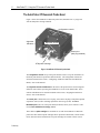
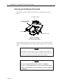
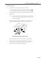
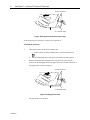
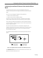
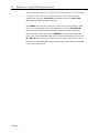
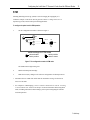
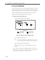
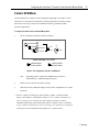
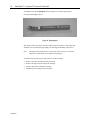
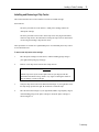
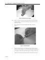
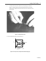
Using the AutoProbe CP-Research Probe Head ThermoMicroscopes 1171 Borregas Avenue Sunnyvale, California 94089 Tel: (408) 747-1600 Fax: (408) 747-1601 85-10283, P2 For AutoProbe CP-Research ThermoMicroscopes ProScan Software Version 1.51b August 15, 2000 Preliminary Copyright Notice Copyright 1999 by ThermoMicroscopes. All rights reserved. No part of this publication my be reproduced or transmitted in any form or by any means (electronic or mechanical, including photocopying) for any purpose, without written permission from ThermoMicroscopes. Trademarks AutoProbe, Piezolever, Ultralever, Microlever, Microcell, Materials Analysis Package, MAP, MapPlot, ProScan, ScanMaster, the TM logo, and ThermoMicroscopes are trademarks of ThermoMicroscopes. Windows is a trademark of Microsoft Corporation. Preliminary Table of Contents Operating Safety ................................................................... 1 Overview ................................................................................ 3 The AutoProbe CP Research Probe Head.......................... 4 Removing and Installing the Probe Head........................... 6 Configuring the AutoProbe CP Research Probe Head for Different Modes ..................................................... 9 STM ..........................................................................................................11 Non-Contact AFM Mode ...............................................................................12 Selecting the Detector ........................................................................................ 13 Phase Detection Microscopy in Non-Contact mode ........................................... 14 Contact AFM Mode .......................................................................................15 Lateral Force Microscopy .................................................................................. 16 Force Modulation Microscopy Mode (Optional)................................................ 17 Loading a Probe Cartridge................................................. 18 The AFM Probe Cartridges ..........................................................................18 Installing and Removing a Chip Carrier .....................................................21 Installing and Removing a Probe Cartridge ...............................................24 Aligning the Deflection Sensor.......................................... 26 How the Deflection Sensor Works ..............................................................26 Adjustments and Indicators ........................................................................27 Alignment Knobs ............................................................................................... 27 The Laser Indicators........................................................................................... 28 Aligning the Laser Spot ...............................................................................29 Preliminary Operating Safety 1 Operating Safety This section includes important information about your AutoProbe CP system with the CP Research probe head. It describes in detail procedures relating to the operating safety of AutoProbe CP and therefore must be read thoroughly before you operate your AutoProbe CP system. WARNING! The protection provided by the AutoProbe CP system may be impaired if the procedures described in the User’s Guide to AutoProbe CP and this supplemental manual are not followed exactly. WARNING! Refer to the section on Operating Safety in the Preface of User’s Guide to AutoProbe CP: Part I: Learning to Use AutoProbe CP: Basic Imaging Techniques before attempting any of the procedures in this supplemental manual. You must be familiar with all safety precautions before you operate your AutoProbe CP system. Previous AutoProbe CP Users, READ THIS! CAUTION Do not use a probe cartridge from an earlier model of AutoProbe CP in the AutoProbe CP Research probe head! Using an incorrect probe cartridge in your AutoProbe CP Research probe head WILL damage the instrument. CAUTION Do not use an AutoProbe CP Research probe cartridge with an earlier model of AutoProbe CP! Using an incorrect probe cartridge with your AutoProbe CP WILL damage the instrument. Preliminary 2 AutoProbe CP: Using the CP Research Probe Head Preliminary Overview 3 Overview This manual provides basic information about using the AutoProbe CP Research probe head. This manual is a supplement to User’s Guide to AutoProbe CP, provided with your instrument. Most of the procedures for using AutoProbe CP Research are the same as for using the earlier versions of AutoProbe CP , and you will be referred to User’s Guide to AutoProbe CP where they are the same. Any procedures that are different are detailed in this supplemental manual. The AutoProbe CP Research probe head allows you to operate in scanning tunneling microscopy (STM) mode, and in a variety of atomic force microscopy (AFM) modes. You will learn about the following procedures: ♦ removing and installing a probe head (AFM and STM modes) ♦ changing the configuration of the probe head (AFM and STM modes) ♦ removing and installing the probe cartridge (AFM and STM modes) ♦ loading a chip carrier in the probe cartridge (AFM modes only) ♦ aligning the deflection sensor (AFM modes only) This manual assumes that your AutoProbe CP Research instrument has been properly installed by a ThermoMicroscopes representative. WARNING! This instrument contains a laser. Use of controls or adjustments or performance of procedures other than those specified herein could result in hazardous laser light exposure. Refer to the information in the AutoProbe CP User’s Guide for basic information on turning the software on and off. Preliminary 4 AutoProbe CP: Using the CP Research Probe Head The AutoProbe CP Research Probe Head Figure 1 shows the AutoProbe CP Research probe head, mounted on an x-y stage and with an STM probe cartridge installed. configuration controls alignment indicators alignment controls sensor port (with plug installed) STM probe cartridge Figure 1. AutoProbe CP Research probe head. The configuration controls on top of the probe head are used to set up the AutoProbe CP Research probe head for operation in different modes. The configuration controls are described in detail in the section, “Configuring AutoProbe CP Research for Different Modes,” later in this manual. The alignment controls and indicators on the front of the probe head are used to align the deflection sensor before operating the AutoProbe CP in one of the AFM modes. These controls and indicators are described in detail in the section, “Aligning the Deflection Sensor,” later in this manual. The sensor port is filled with a screw-in plug. You remove the plug to install the optional capacitance sensor, used in scanning capacitance microscopy (SCM). The Force Modulation jack in the rear of the probe head (not shown) allows you to connect a cable used in force modulation microscopy (FMM). Three different probe cartridges are available for use with the AutoProbe CP Research probe head. The different probe cartridges allow operation in STM mode, Contact AFM mode, and Non-Contact AFM mode. The probe cartridges are similar to those used in Preliminary The AutoProbe CP Research Probe Head 5 earlier versions of AutoProbe CP, but the probe cartridges for different models have different connections and are not compatible. Probe cartridges for the different models have different finishes: ♦ AutoProbe CP Research probe cartridges are blue. ♦ Other AutoProbe CP probe cartridges are black. Previous AutoProbe CP Users, READ THIS! CAUTION Do not use a probe cartridge from an earlier model of AutoProbe CP in the AutoProbe CP Research probe head! Using an incorrect probe cartridge in your AutoProbe CP Research probe head WILL damage the instrument. Do not use an AutoProbe CP Research probe cartridge with an earlier model of AutoProbe CP! Using an incorrect probe cartridge with your AutoProbe CP WILL damage the instrument. Preliminary 6 AutoProbe CP: Using the CP Research Probe Head Removing and Installing the Probe Head The AutoProbe CP Research probe head is installed on a manual XY stage, shown in Figure 2. XY stage connector manually operated XY translation stage Y translation screw X translation screw Figure 2. The XY stage, with no probe head installed. The probe head slides onto the two support arms of the XY stage. An electrical connector on the rear of the head plugs into the XY stage connector, mounted on the rear of the XY stage. CAUTION Any time that you load a cartridge or remove a cartridge, you must raise the probe head first. If you don’t raise the head, the cantilever tip will scrape across the surface of your sample. The tip and the sample will be damaged. CAUTION Make sure the sample modulation cable, used in force modulation microscopy, is disconnected whenever you remove the CP Research head. Otherwise you will pull on the scanner and damage it or knock ScanMaster out of alignment. Preliminary Removing and Installing the Probe Head 7 To remove the probe head: 1. 2. Turn off the power to the probe head and the power to the laser: a. Deselect Head ON from the Mode menu or click the Head ON icon, b. Turn the LASER ON/OFF switch of the probe head to the OFF position. . Use the z direction pad to raise the stage to provide clearance between the probe and the sample. Note: If you are using AutoProbe CP with CP Optics, move the objective lens out of the way of the probe head by rotating the swing arm towards you before you raise the stage. 3. Remove an installed probe cartridge by grabbing the two prongs (using one or two hands) and sliding the cartridge out towards you, as shown in Figure 3. Figure 3. Removing the cartridge from the probe head. Set the probe cartridge on a flat surface with the cantilever facing upwards. 4. Remove the probe head by sliding it off the support arms of the XY stage, as shown in Figure 4. As you slide the head off the XY stage, the electrical connector on the back of the probe head is disengaged. Preliminary 8 AutoProbe CP: Using the CP Research Probe Head electrical connectors XY Translation Stage Figure 4. Removing the probe head from the XY stage. Set the probe head on a flat surface or back into its original box. To reinstall the probe head: 1. Turn off the power to the probe head and the laser: a. Deselect Head ON from the Mode menu or click the Head ON icon, . b. 2. Turn the LASER ON/OFF switch of the probe head to the OFF position. Slide the probe head onto the support arms of the XY stage. The electrical connector on the head plugs into the XY stage connector, mounted on the back of the support arms, as shown in Figure 5. electrical connectors XY Translation Stage Figure 5. Installing the probe head. The probe head is now installed. Preliminary Configuring the AutoProbe CP Research Probe Head for Different Modes 9 Configuring the AutoProbe CP Research Probe Head for Different Modes As described in the earlier section, you can use the configuration switches of the AutoProbe CP Research probe head to configure the instrument for operation in different modes. There are two steps in changing the configuration of the AutoProbe CP: 1. Make any necessary hardware changes. 2. Make any necessary software configuration changes. In the first step you change scanners, probe heads, switch positions, probe cartridges, cantilever cassettes, and accessories as necessary for the mode you wish to operate in. In the second step you change the selected head type, scanner, head mode and cantilever in the ProScan Database Configuration Dialog box, and select different signal channels in the Input Configuration dialog box. This section of the manual describes how to set the hardware configuration on the AutoProbe CP Research probe head to operate in different modes. You will be referred to the relevant sections of User’s Guide for AutoProbe CP for information about other necessary changes to the software. The configuration switches and indicators of the CP Research probe head are shown in Figure 6. STM STM NC-AFM NC-AFM AFM FMOD DET. A ON C-AFM/FMOD C-AFM C-AFM/LFM LASER DET. B LFM OFF selected state/ switch position switch position doesn't matter Figure 6. The configuration switches and indicators of the CP Research probe head. The LASER ON/OFF switch turns the laser used on the deflection sensor on and off. A red light in the switch turns on when the laser is on. Preliminary 10 AutoProbe CP: Using the CP Research Probe Head Mode selection proceeds from left to right in the form of a decision tree, where the setting of switches on the left side of the head allows selection of further options using the switches to the right. Three mode switches with indicator lights and a detector switch allow you to select different modes of operation. The STM/AFM switch determines whether the CP Research Probe head operates in STM mode, or in one of the AFM modes. When operating as an AFM, the NC-AFM/C-AFM switch determines whether the head operates in non-contact or contact AFM modes. When operating in contact AFM mode, the FMOD/LFM switch determines whether the head operates in force modulation AFM mode or in Lateral Force Microscopy mode. The DET. A/DET. B switch allows you to switch between two different detectors in NC-AFM mode and in C-AFM/FMOD mode. The green LEDs indicate which mode the AutoProbe CP Research Probe Head is in. Preliminary Configuring the AutoProbe CP Research Probe Head for Different Modes 11 STM Scanning tunneling microscopy (STM) is used for imaging the topography of a conductive sample. It can also be used to generate current vs. voltage curves in I-V Spectroscopy mode, and for other specialized applications. To configure the probe head for STM operation: 1. Set the configuration switches as shown in Figure 7: STM STM NC-AFM NC-AFM AFM FMOD DET. A ON C-AFM/FMOD C-AFM C-AFM/LFM LASER DET. B LFM OFF switch settings for STM mode selected state/ switch position switch position doesn't matter Figure 7. The configuration controls in STM mode. The STM indicator light turns green. 2. Install an STM tip and cartridge. 3. Make the necessary changes to the software configuration for STM operation.* * Disconnect the NC-AFM clock cable from the AutoProbe CP stage for the lowest noise level in STM * See “Chapter 2: STM Imaging,” in User’s Guide to AutoProbe CP: Part II: Learning to Use AutoProbe CP: Advanced Techniques for more information about using STM mode, including instructions about loading a probe tip and configuring the software for STM operation. Preliminary 12 AutoProbe CP: Using the CP Research Probe Head Non-Contact AFM Mode Non-Contact AFM mode (NC-AFM) is used for imaging the topography of a sample. NCAFM is also used for magnetic force microscopy (MFM), electrostatic force microscopy (EFM), phase imaging (phase detection microscopy), and other specialized applications. The CP Research probe head provides two different detectors for NC-AFM mode, allowing you to choose the best detector for use with your sample. To configure the probe head for NC-AFM operation: 1. Set the configuration switches as shown in Figure 8: STM STM NC-AFM NC-AFM AFM FMOD DET. A ON C-AFM/FMOD C-AFM C-AFM/LFM LASER DET. B LFM OFF Switch settings for NC-AFM mode Detector A selected state/ switch position switch position doesn't matter Figure 8. The configuration controls in NC-AFM/Det. A mode. The NC-AFM indicator light turns green. Note: You can select either Detector A or Detector B for use in NC-AFM. The next section provides some information on selecting the detector. 2. Install an NC-AFM cantilever and probe cartridge. 3. Make the necessary changes to the software configuration for NC-AFM operation.* * Refer to “Chapter 1: NC-AFM, IC-AFM and MFM Imaging,” in User’s Guide to AutoProbe CP: Part II: Learning to Use AutoProbe CP: Advanced Techniques, for more information about using the non-contact modes of SPM. Preliminary Configuring the AutoProbe CP Research Probe Head for Different Modes 13 Selecting the Detector The DET. A/ DET. B switch controls which detector is being used in NC-AFM and Force Modulation mode. You select the detector in NC-AFM depending upon the type of sample you are imaging, and whether you are using non-contact or intermittent contact mode. Detector A is more useful when imaging a sample that must never touch the probe tip. This configuration is best for fragile or sticky samples. For example, it is very easy to image adhesive tape or polysaccharides in this configuration. Detector B is less sensitive to erratic damping of the tip oscillation as occurs for certain sample types. For example, samples which have adsorbed water (hygroscopic) or samples with thin organic layers (contamination) covering the actual sample surface are better imaged using detector B. Polymers typically fall under this category. Samples which image well using intermittent contact are best imaged using detector B. Note: In Det. B mode the NC frequency sweep will show a peak at low frequencies (≈20 kHz). This peak is an artifact which does not affect the operation of the instrument. The actual resonance peaks are at higher frequencies. For hard, clean and dry samples either detector configuration is appropriate. The user should use the above recommendations as general guideline. Try out what’s best on your samples! Preliminary 14 AutoProbe CP: Using the CP Research Probe Head Phase Detection Microscopy in Non-Contact mode The CP Research probe head allows you to use phase detection microscopy (PDM) in conjunction with NC-AFM. This allows you to image both the topography and the changes in phase produced by changes in the material properties of the sample. This technique can be used with both the A detector and the B detector. To use PDM in NC-AFM: 1. Set up the AutoProbe CP Research probe head for NC-AFM as described above. 2. Select Input Config from the Setup menu in ProScan Data Acquisition Software version 1.5. 3. Select Phase from the list of available signals.* Note: Depending upon scan speed, an LP Filter value of 1-2 may be desirable. 4. Image the sample while viewing the Topography and Phase signals. * Refer to “Chapter 1: ProScan Data Acquisition,” of User’s Guide to AutoProbe CP and M5: Part III: Software Reference, for more information about selecting signals in the Input Configuration dialog box. Preliminary Configuring the AutoProbe CP Research Probe Head for Different Modes 15 Contact AFM Mode Contact AFM mode (C-AFM) is used for imaging the topography of a sample. It is also used for force versus distance measurements, scanning capacitance microscopy (SCM), lateral force microscopy (LFM), force modulation microscopy (FMM), and other specialized applications. To configure the probe head for contact AFM operation: 1. Set the configuration switches as shown in Figure 9: STM STM NC-AFM NC-AFM AFM FMOD DET. A ON C-AFM/FMOD C-AFM C-AFM/LFM LASER DET. B LFM OFF switch settings for C-AFM selected state/ switch position switch position doesn't matter Figure 9. The configuration controls in C-AFM mode. Note: Depending upon the setting of the FMOD/LFM switch, the CAFM/FMOD or C-AFM/LFM light turns green. 2. Install a contact cantilever and probe cartridge. 3. Make the necessary additional changes to the software configuration for C-AFM operation.* * Refer to “Chapter 2, Setting Up to Take an Image, “Chapter 3: Taking an AFM Image,” and “Chapter 4: Taking Better Images,” in User’s Guide to AutoProbe CP: Part I: Learning to Use AutoProbe CP: Basic Imaging Techniques, for more information about using contact AFM mode. Refer to “Chapter 4: Force vs. Distance,” in User’s Guide to AutoProbe CP: Part II: Learning to Use AutoProbe CP: Advanced Techniques, for more information about using force vs. distance mode. Preliminary 16 AutoProbe CP: Using the CP Research Probe Head Lateral Force Microscopy Lateral Force Microscopy (LFM) is used to study the material properties of a sample. To configure the probe head for LFM operation: 1. Set the configuration switches as shown in Figure 10: STM STM NC-AFM NC-AFM AFM FMOD DET. A ON C-AFM/FMOD C-AFM C-AFM/LFM LASER DET. B LFM OFF switch settings for C-AFM/LFM modes selected state/ switch position switch position doesn't matter Figure 10. The configuration controls in LFM mode. The C-AFM/LFM indicator light turns on. 2. Make the necessary additional changes to the hardware and software configuration for LFM operation.* * Refer to “Chapter 3: LFM Imaging,” in User’s Guide to AutoProbe CP: Part II: Learning to Use AutoProbe CP: Advanced Techniques, for more information about using LFM mode. Preliminary Configuring the AutoProbe CP Research Probe Head for Different Modes 17 Force Modulation Microscopy Mode (Optional) Force Modulation Microscopy (FMM) is used to study material properties of a sample. Note: The use of FMM requires a Materials Analysis Package (MAP) for AutoProbe CP. To configure the probe head for FMM operation: 1. Set the configuration switches as shown in Figure 11: STM STM NC-AFM NC-AFM AFM FMOD DET. A ON C-AFM/FMOD C-AFM C-AFM/LFM LASER DET. B LFM OFF switch settings for C-AFM/FMOD modes Detector A selected state/ switch position switch position doesn't matter Figure 11. The configuration controls in Fmod mode. The C-AFM/FMOD indicator light turns on. 3. Make the necessary additional changes to the hardware and software configuration for FMM operation.* * Refer to the documentation on using the AutoProbe CP with Force Modulation Microscopy for complete instructions on using FMM. Preliminary 18 AutoProbe CP: Using the CP Research Probe Head Loading a Probe Cartridge The CP Research probe head uses new probe cartridges that are not compatible with earlier version of AutoProbe CP. Probe cartridges for the different models have different finishes: ♦ AutoProbe CP Research probe cartridges are blue. ♦ Other AutoProbe CP probe cartridges are black. The AutoProbe CP probe head has three different probe cartridges, each used for different applications: ♦ STM ♦ Contact AFM ♦ Non-contact AFM The procedures for using the AutoProbe CP Research STM cartridge are the same as for earlier versions. Refer to “Chapter 2: STM Imaging,” of User’s Guide to AutoProbe: Part II: Learning to Use AutoProbe CP: Advanced Techniques, for more information about using the STM probe cartridge. The AutoProbe CP Research probe cartridges for C-AFM and NC-AFM are described in the next section. The AFM Probe Cartridges Atomic force microscopy (AFM) works by bringing a tiny, extremely sharp probe tip into contact with or in near proximity to a sample. In AutoProbe CP Research the sample is rastered beneath the tip. As the sample moves the probe is deflected by changes in the height of the sample surface. The probe is at the end of a cantilever, which extends from the end of a microfabricated cantilever chip. Cantilever chips are available in both mounted and unmounted versions. Mounted cantilever chips are pre-mounted on a disposable ceramic chip carrier. Unmounted cantilever chips can be used with an optional unmounted chip carrier. A mounted cantilever chip is shown in Figure 12 (the size of the cantilevers in the figure is greatly exaggerated). Preliminary Loading a Probe Cartridge 19 (not to scale) ceramic chip carrier cantilever slots for three-point mount probe cantilever chip Probe on cantilever points down when cartridge is correctly inserted Figure 12. Microfabricated cantilever chip mounted on chip carrier. The chip carrier has three slots in it, arranged in a triangle. These three slots fit over three balls in the three-point mount of the probe cartridge, shown in Figure 13. A spring clip on the cartridge holds the slots securely against the balls, holding the chip carrier in place. The spring clip has two small notches for the prongs of the spring clip tool. 3-point contacts for probe head handling prongs 3-point mount for carrier* chip carrier spring clip * one ball hidden beneath spring clip Figure 13. The AFM probe cartridge The probe cartridge has two handling prongs, which allow you to grasp it easily for removal and installation. The NC-AFM probe cartridge has a small piezoelectric actuator that drives the vibration of the cantilever for non-contact operation. You load a cantilever chip into the NC-AFM probe cartridge in the same way you load a cantilever into the contact AFM cartridge. The cartridge slides into a slot in the probe head, where another three-point mount locks the cartridge into place. Preliminary 20 AutoProbe CP: Using the CP Research Probe Head You must use the special spring tool, shown in Figure 14, to lift the spring clip for removing and installing a carrier. Figure 14. The spring tool. The spring tool has two prongs on the end. These prongs fit in notches of the spring clip, and allow you to lift the spring clip slightly for removing and installing a chip carrier. Note: The spring tool should be kept in a secure place when not in use. You will be charged for a replacement if you misplace the spring tool. You follow these general steps to load a probe in a probe cartridge: Preliminary 1. Remove the probe cartridge from the probe head. 2. Remove the chip carrier from the probe cartridge. 3. Install a chip carrier in the probe cartridge. 4. Install the probe cartridge in the probe head. Loading a Probe Cartridge 21 Installing and Removing a Chip Carrier This section describes how to load a cantilever cassette in an AFM cartridge. General Notes: The same procedures are used with the C-AFM probe cartridge and the NCAFM probe cartridge. The same procedures can be used to load a chip carrier carrying an unmounted cantilever chip. Refer to the instructions on using the chip carrier for instructions on removing and loading a chip onto the carrier. These procedures are written for a right-handed person. A left-handed person may wish to reverse the hands used. To mount a new chip carrier on the cartridge: 1. Place the probe cartridge on a flat surface, with the handling prongs facing to your right and the spring clip facing up. 2. Remove a new chip carrier from the box of chip carriers. CAUTION Hold the chip carrier by the ceramic plate. Don’t let your fingers touch the microfabricated cantilever chip, which is very fragile. Touching the cantilever chip can damage or break off the tips. 3. Grasp the chip carrier between the thumb and forefinger of your right hand, with the chip facing up and to the right. Be careful not to touch the chip! 4. Place the three unused fingers of your right hand (middle, ring and pinky fingers) on the handling prongs of the probe cartridge to steady the probe cartridge, as shown in Figure 15. Preliminary 22 AutoProbe CP: Using the CP Research Probe Head Figure 15. Steadying the probe cartridge. Note: Figure 15 was taken to show the position of the fingers for steadying the probe cartridge. Normally, you would also be holding the chip carrier between your thumb and forefinger. 5. Place the chip carrier near the three-point mount carefully, as shown in Figure 16. Figure 16. Lifting the spring clip. 6. Grasp the spring tool with your other hand and place the tool prongs under the spring clip, as shown in Figure 16. The curved side of the tool prongs should face down, and the flat side of the prongs should engage the notches in the spring clip. 7. Preliminary Gently lift the spring clip by pressing down gently on the handle of the clip tool. Loading a Probe Cartridge 8. 23 Carefully slide the chip carrier under the lip of the spring clip, as shown in Figure 17. Slide the chip carrier under the spring clip until you feel the balls engage the slots. Wiggle the chip carrier from side to side to ensure that all three balls fit snugly. Figure 17. Inserting the chip carrier A correctly installed chip carrier is shown in Figure 18. clip cantilever chip Correct All three balls are engaged in the slots. Figure 18. The chip carrier, correctly inserted under the spring clip. Preliminary 24 AutoProbe CP: Using the CP Research Probe Head 9. Lower the spring clip to clamp the chip carrier by slowly raising the handle of the spring clip tool. 10. Disengage the spring tool from the notches in the clip spring and put the tool in a secure place. The probe cartridge can now be installed in the probe head, as described in the next section of this manual. To remove the chip carrier from the cartridge: 1. Reverse the procedure for installing the chip carrier. Installing and Removing a Probe Cartridge This section describes the procedures for installing and removing the probe cartridge from the probe head. The same procedures are used to install and remove the STM, NC-AFM and C-AFM probe cartridges. CAUTION Any time that you load a cartridge or remove a cartridge, you must raise the probe head first. If you don’t raise the head, the cantilever tip will scrape across the surface of your sample. The tip and the sample will be damaged. To install the probe cartridge in the probe head: 1. Move the Z stage up using the z direction pad in the Move mode window. 2. Hold the cartridge by the two prongs. You can use one or both hands. Make sure you hold it with the cantilever chip facing down, so that the tip can contact the sample. 3. Insert the cartridge into the head by sliding it along the ledge. CAUTION Make sure the cantilever chip faces down. The cartridge should fit snugly inside the probe head. Wiggle the cartridge in and out a bit to make sure that the three-point mount secures the cartridge properly. Preliminary Loading a Probe Cartridge 25 CAUTION Any time that you load a cartridge or remove a cartridge, you must raise the probe head first. If you don’t raise the head, the cantilever tip will scrape across the surface of the sample. The sample and the tip will be damaged. To remove the probe cartridge from the probe head: 1. Move the Z stage up using the z direction pad in the Move mode window. When the probe head has been raised, you are ready to load the probe cartridge. 2. Grasp the two handling prongs (using one or two hands) and slide the cartridge out towards you. 3. Place the cartridge on a flat surface, with the chip carrier facing up. Preliminary 26 AutoProbe CP: Using the CP Research Probe Head Aligning the Deflection Sensor This section describes the alignment procedures for the deflection sensor of the AutoProbe CP Research probe head. The section provides a description of the deflection sensor, an introduction to the controls and indicators used in aligning the sensor, and instructions on aligning the deflection sensor. How the Deflection Sensor Works In order for AutoProbe CP to work, the probe head must measure extremely small movements of the cantilever as the cantilever is moved across the surface of the sample. AutoProbe CP uses a deflection sensor to measure these movements. The deflection sensor works by reflecting a laser beam off the back of the cantilever onto a position-sensitive photodetector (PSPD). This technique is known as "beam bounce" detection. As the cantilever bends, the position of the laser spot on the PSPD shifts. The shift in position gives a measure of how much the cantilever has been deflected. For the AutoProbe CP Research probe head, the laser beam is first reflected off an adjustable mirror onto the cantilever. The reflected signal from the cantilever then reflects off a second adjustable mirror onto the PSPD, as shown in Figure 19. PSPD adjustable mirrors laser diode laser path feedback loop cantilever Image PZT scanner Figure 19. The light path of the laser beam Preliminary Aligning the Deflection Sensor 27 For proper use of the AFM, two conditions must be met: 1. The laser spot must hit the end of the cantilever, as shown in Figure 20. triangular diving board cantilever tip laser spot Figure 20. Correct position for the laser spot. 2. The intensity of the reflected laser beam hitting the PSPD must be above a certain level. When the laser spot is aligned properly on the PSPD, the laser intensity indicator is bright green and none of the red laser position indicators are illuminated. You can accidentally align the deflection sensor with the laser spot reflecting off one of the legs of the cantilever, the cantilever chip, or the sample surface. If you do this, the alignment indicators may show that the deflection sensor is aligned properly, but the unit will not work properly. Adjustments and Indicators You use the alignment knobs to align the laser spot, while observing the results of these adjustments with the laser position and laser intensity indicators. The Alignment Knobs The deflection sensor is aligned when the laser beam reflects off the back of the cantilever and onto the correct position on the PSPD. The AutoProbe CP Research probe head uses two adjustable mirrors to steer the laser beam in the deflection sensor. The cantilever mirror steers the laser beam onto the cantilever. The detector mirror steers the reflected beam from the cantilever onto the PSPD. The angle of each mirror relative to the laser, cantilever, and detector can be changed with two adjustment knobs, changing the path of the laser beam. The adjustment knobs are shown in Figure 21. Preliminary 28 AutoProbe CP: Using the CP Research Probe Head alignment and intensity indicators U D U DETECTOR ALIGNMENT alignment knobs D CANTILEVER ALIGNMENT L L R R Figure 21. Front view of the probe head, showing the detector alignment controls and indicators. The cantilever alignment knobs steer the laser spot onto the cantilever. The laser spot moves in the direction indicated by the arrows on the up/down (U/D) knob and the left/right (L/R) knob. The detector alignment knobs steer the laser spot onto the deflection sensor. The laser spot moves in the direction indicated by the arrows on the down/up (D/U) knob and the left/right (L/R) knob. The Laser Indicators The laser position and intensity indicators, located on the AutoProbe CP Research probe head and shown in shown in Figure 22, allow you to observe the results of any adjustments you make. top position indicator laser intensity (A+B) indicator right position indicator left position indicator bottom position indicator Figure 22. The laser position and intensity indicators. Preliminary Aligning the Deflection Sensor 29 Aligning the Laser Spot These procedures assume that the CP Research probe head has been configured properly for AFM operation, as described earlier in this manual. WARNING! Use of controls or adjustments or performance of procedures other than those specified herein may result in hazardous laser light exposure. To steer the laser spot onto the cantilever: 1. Make sure that the power to the probe head is on. If the power to the probe head is turned off, turn it on by clicking the Head ON icon, 2. . Turn the Laser ON/OFF switch on the probe head to ON. The laser on/off indicator light in the switch turns on when the laser is on. 3. Steer the laser spot onto the cantilever chip using the cantilever alignment knobs. When you see an intense red reflection the laser spot is at the front of the cantilever chip, above the cantilever itself. 4. Focus on the cantilever using the optical view as described in “Chapter 2: Setting Up to Take an Image,” in User’s Guide to AutoProbe CP: Part II: Learning to Use AutoProbe CP: Basic Imaging Techniques. 5. Walk the laser spot to the end of the cantilever in a zig-zag fashion, using sequential ¼ turn increments of both cantilever alignment knobs, as shown in Figure 23. Figure 23. The laser’s path on the cantilever. 6. Carefully center the laser spot on the end of the cantilever, above the tip, using the cantilever alignment knobs. Preliminary 30 AutoProbe CP: Using the CP Research Probe Head Helpful Hints: When first steering the laser spot onto the cantilever chip, you can observe the position of the spot on the underlying surface. By doing this, you can observe the direction the beam moves when you adjust the knobs. Don’t try to maximize the brightness of the laser spot you see in the optical view. Your goal is to produce the maximum amount of reflected light hitting the PSPD. When the spot is positioned so that most of the laser beam is reflected onto the PSPD, the laser spot on the cantilever may not look bright in the optical view. You may need to realign the position of the laser spot on the cantilever tip using the laser intensity indicator, but you cannot do this until the laser spot reflects upon the PSPD. To steer the reflected laser spot into the PSPD: 1. Adjust the detector alignment knobs on the left-hand side of the probe head to align the laser spot with the center of the PSPD, using the laser position indicator on the front of the probe head, as shown in Figure24. The goal is to have the central green LED brightly illuminated, with none of the red LEDs illuminated. If the laser spot is low and to the right.... L turn the LR knob towards the L. R If the laser spot is low and centered... D turn the DU knob towards the U. U Laser spot properly aligned. Figure 24 . Steering the laser spot onto the PSPD. Preliminary Aligning the Deflection Sensor 31 After making adjustments to the left/right position, you may need to readjust the up/down position, and vice versa. Near the correct position, the red lights are very sensitive and you may find it difficult to position the detector mirror so that all of the red lights stay off. The deflection sensor is now aligned. Details on imaging are given in Chapter 3 of User’s Guide to AutoProbe CP: Part II: Learning to use AutoProbe CP: Basic Imaging Techniques. Preliminary 32 AutoProbe CP: Using the CP Research Probe Head Preliminary