1
US008363656B2
(12) Ulllted States Patent
(10) Patent N0.:
Klink et a].
(54)
(45) Date of Patent:
MULTIPLE VIRTUAL MACHINES SHARING
A SINGLE [P ADDRESS
7,830,882 B2 *
7,908,353 B2 *
(75) Inventors: Jeffrey Klink, Ajax (CA); Mikhail
Shoykher, Thomhill (CA)
(*)
Notice:
’
OTHER PUBLICATIONS
_
_
_
the Technical Professional”, VMWare User’s Manual, Sep. 16, 2005,
' Cor oration Armonk NY (Us)
P
10/2009 Hepburn
VMWARE, “Workstation 5 Powerful Virtual Machine Software for
Assi nee International Business Machines
g
Jan. 29, 2013
11/2010 Johnson ...................... .. 370/392
3/2011 Hepburn ..................... .. 709/223
2009/0259740 A1
(73)
US 8,363,656 B2
pp. 1-466 http://www.vmware.com/pdf/wsSfmanual.pdf.
’
Subject to any disclaimer, the term of this
International Search Report and Written Opinion of the ISA dated
S .14, 2011iI t
t'
1A 1' t' N .PCT/EP2011/065945.
ep
H mm Iona pp lea Ion 0
patent is extended or adjusted under 35
* Cited by examiner
U.S.C. 154(b) by 198 days.
Primary Examiner * AyaZ Sheikh
(21)
APP1~ N05 12/882’795
Assistant Examiner * Blanche Wong
(22)
Filed:
(74) Attorney, Agent, or Firm * Martin & Associates, LLC
sep- 15, 2010
(57)
(65)
Prior Publication Data
Us 2012/0063458A1
(51)
_
_
_
Man 15, 2012
share the same IP address on an external network address
space. The Virtual machines reside on one or more physical
host comP uter s y stems. A Virtual network mana g er handles
Illt- Cl-
H04L 12/28
H04L 12/56
(52)
(58)
ABSTRACT
A method and apparatus allow mult1ple V1rtual machmes to
(2006-01)
(2006-01)
network tra?ic from a physical interface on the host computer
and forwards network data to the appropriate Virtual machine
US. Cl. ..................................................... .. 370/392
Field of Classi?cation Search ................. .. 370/392
based on a destination port number. Data packets on the
external network each have a destination and source port
See application ?le for complete Search history,
number. The Virtual network manager uses a port range table
References Cited
tion port numbers for incoming data packets. Each of the
Virtual machines is assigned a unique destination port range
US. PATENT DOCUMENTS
in the port range table and incoming data tra?ic on the exter
nal network is routed to the receiving Virtual machines based
on the destination port number in the data packet.
that associates each Virtual machine with a range of destina
(56)
6,665,295 B1*
7,228,337 B1
7,444,408 B2 *
7,706,303 B2
12/2003
Burns et a1. ................. .. 370/389
6/2007 Bornstein et al.
10/2008
Rajavelu et a1. ............ .. 709/227
18 Claims, 5 Drawing Sheets
4/2010 Bose et a1.
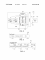
630
’
iiios'iiiggzure Manitoba Viviana;
machines; Wit?) A iiing?a E53
1
ms teas.’
e
Manager
Gon?gure
wasAA‘slime;
{Dori Range
Network
‘f‘abée
Configure Eenemaraé Ports To Use’
The PM Nowhere in The
Ansignee; §'»“‘cii’s Ran ga es "Fixes
Virtue; Machines
Route mean/15:19 {335a £32“; A
Physieai interface “E9 the Mui?'pie
Virtue;
S-eaii'naiion
Machines
WmEma-a1
in The Qata
‘inn
Packet
_
US. Patent
Jan. 29, 2013
US 8,363,656 B2
Sheet 2 0f 5
3,23
2m
2%
23,4
1*
vmmi
Mimi
621mm‘ A
ééachim 8
i ' 'E’A
Mme;
am
i
K
?aia Faakat
‘ am
2.3,
m
ma
F
US. Patent
Jan. 29, 2013
Sheet 3 of5
US 8,363,656 B2
5%)
F166, 5
US. Patent
Jan. 29, 2013
@mfiwa
Sheet 4 of5
itiggiia
a
iuaé
US 8,363,656 B2
:33 1%
US. Patent
Jan. 29, 2013
yin-NM . , , , . “Mam:
Yas
vii.-
w
@wwar? “£33 Virmai ééaehiw
FIG. 7
Sheet 5 of5
US 8,363,656 B2
US 8,363,656 B2
1
2
MULTIPLE VIRTUAL MACHINES SHARING
A SINGLE IP ADDRESS
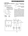
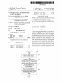
FIG. 1 is a block diagram of a computer system With a
virtual netWork manager utiliZing a port range table to enable
multiple virtual computers to use a single netWork IP address
as described herein;
BACKGROUND
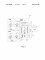
FIG. 2 is a block diagram that illustrates hoW data packets
1. Technical Field
are routed to multiple virtual machines residing on a host
This disclosure generally relates to computer systems, and
computer by a virtual netWork manager;
FIG. 3 is a block diagram that represents a data packet sent
over the netWork described herein;
FIG. 4 is a block diagram that shoWs an example ofa port
more speci?cally relates to sharing a single IP address among
multiple virtual machines residing on one or more physical
host computers.
2. Background Art
A single host computer may hold multiple virtual instances
range table;
of a computer referred to as a virtual machine. A virtual
machine is sometimes de?ned as an e?icient and isolated
multiple physical hosts With virtual machines utiliZing the
FIG. 5 is a block diagram similar to FIG. 1 that illustrates
duplicate of a real machine. A virtual machine is thus a
duplicate or instance of a virtual computer residing on a
same IP address;
physical host computer. A virtual machine is sometimes also
called a logical partition. A principle advantage of a virtual
address among multiple virtual machines; and
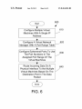
FIG. 6 is a method ?oW diagram for sharing a single IP
FIG. 7 is an example of a method ?oW diagram for routing
incoming data to multiple virtual machines based on a port
range table according to step 630 in FIG. 6.
machine system is that multiple operating system (OS) envi
ronments can co-exist on the same computer in isolation from
each other. In addition, a virtual machine can provide an
instruction set architecture that is different from that of the
real machine. A virtual machine can be utiliZed to improve
20
DETAILED DESCRIPTION
application provisioning, maintenance, high availability and
Described herein is an apparatus and method for multiple
disaster recovery.
Virtual machines residing on a physical host computer
typically must share a physical netWork interface of the host
computer. The physical netWork interface of the host com
puter is connected to an external netWork. As used herein, an
external netWork is any netWork residing outside of a single
virtual machines to share the same IP address on an external
25 netWork address space. The virtual machines reside on one or
physical machine and may/may not be indirectly contacted
30
more physical host computer systems. A virtual netWork
through a series of ?reWalls. In some cases, it is advantageous
to have a single IP address from the external netWork address
port range table that associates each virtual machine With a
range of destination port numbers for incoming data packets.
space assigned to the physical interface of the host computer.
Virtual machines residing on the host have their oWn virtual
netWork interfaces connected to the same external netWork
35
via the ho st physical interface. In the prior art, there have been
various approaches to having multiple virtual machines use
40
The disclosure and claims herein are directed to multiple
virtual machines (virtual computers) that collectively are
assigned the same IP address on an external netWork address
space. The virtual machines reside on one or more physical
and forWards netWork data to the appropriate virtual machine
cessors 110, a main memory 120, a mass storage interface
50
tion port numbers for incoming data packets. Each of the
virtual machines is assigned a unique destination port range
60
display interface 140, and netWork interface 150 may actually
be implemented in adapters coupled to I/O slots 180. An I/O
65
adapter is one suitable netWork interface 150 that may be
implemented in an external card that is plugged into one of the
I/ O slots 180. In addition, other I/ O devices such as modems
can be plugged into one of the I/O slots 180.
Main memory 120 preferably contains an operating system
VIEWS OF THE DRAWING(S)
The disclosure Will be described in conjunction With the
ments, and:
storage devices 155, to computer system 100. One speci?c
type of direct access storage device 155 is a readable and
Writable CD-RW drive, Which may store data to and read data
from a CD-RW 195. Note that mass storage interface 130,
BRIEF DESCRIPTION OF THE SEVERAL
appended draWings, Where like designations denote like ele
130, a display interface 140, and a netWork interface 150, and
a plurality of I/O slots 180. These system components are
interconnected through the use of a system bus 160. Mass
storage interface 130 is used to connect mass storage devices
With a computer readable medium, such as direct access
55
The foregoing and other features and advantages Will be
apparent from the folloWing more particular description, as
illustrated in the accompanying draWings.
system. HoWever, those skilled in the art Will appreciate that
the disclosure herein applies equally to any computer system
capable of being connected to an external netWork. As shoWn
in FIG. 1, computer system 100 comprises one or more pro
netWork tra?ic from a physical interface on the ho st computer
in the port range table and incoming data traf?c on the exter
nal netWork is routed to the receiving virtual machines based
on the destination port number in the data packet.
Referring to FIG. 1, a computer system 100 is one suitable
implementation of a computer system that includes a virtual
netWork manager as described herein. Computer system 100
is an International Business Machines Corporation (IBM®)
PoWer System Which can run multiple operating systems
including the IBM® i operating system and Linux operating
45
host computer systems. A virtual netWork manager handles
based on a destination port number. Data packets on the
external netWork each have a destination and source port
number. The virtual netWork manager uses a port range table
that associates each virtual machine With a range of destina
Each of the virtual machines is assigned a unique destination
port range in the port range table and incoming data tra?ic on
the external netWork is routed to the receiving virtual
machines based on the destination port number in the data
packet.
the same physical netWork interface.
BRIEF SUMMARY
manager handles netWork traf?c from a physical interface on
the host computer and forWards netWork data to the appro
priate virtual machine based on a destination port number.
Data packets on the external netWork each have a destination
and source port number. The virtual netWork manager uses a
121. Operating system 121 is preferably a multitasking oper
ating system, such as AIX, or Linux; hoWever, those skilled in
US 8,363,656 B2
3
4
the art will appreciate that the spirit and scope of this disclo
Although computer system 100 is shown to contain only a
single processor and a single system bus, those skilled in the
sure is not limited to any one operating system. Any suitable
operating system can be used. Operating system 121 is a
sophisticated program that contains low-level code to manage
the resources of computer system 100. Some of these
practiced using a computer system that has multiple proces
resources are processors 110, main memory 120, mass stor
used preferably each include separate, fully programmed
age interface 130, display interface 140, network interface
150, system bus 160, and I/O slots 180. Each virtual machine
may also have an operating system. The operating system in
microprocessors that are used to off-load compute-intensive
processing from processor 110. However, those skilled in the
art will appreciate that these functions may be performed
using I/O adapters as well.
art will appreciate that a virtual network manager may be
sors and/or multiple buses. In addition, the interfaces that are
each virtual machine or partition may be the same as the
Display interface 140 is used to directly connect one or
operating system in virtual machines, or may be a completely
more displays 165 to computer system 100. These displays
165, which may be non-intelligent (i.e., dumb) terminals or
different operating system. Thus, one virtual machine can run
the AIX operating system, while a different virtual can run
fully programmable workstations, are used to provide system
another instance of AIX, possibly a different release, or with
different environment settings (e.g., time Zone or language).
In this manner the virtual machines can provide completely
administrators and users the ability to communicate with
computer system 100. Note, however, that while display
interface 140 is provided to support communication with one
or more displays 165, computer system 100 does not neces
different computing environments on the same physical com
puter system. The memory further includes a software appli
cation 122. The memory includes a virtual network manager
123. The virtual network manager includes an interceptor
124, a mixer 125 and a port range table 126. The memory also
sarily require a display 165, because all needed interaction
20
face 150, eg web client based users.
Network interface 150 is used to connect computer system
100 to other computer systems or workstations 175 via net
includes one or more virtual machines or computers 127.
Each of these entities in the memory is described further
below.
The virtual machine(s) 127 are shown to reside within main
memory 120. However, one skilled in the art will recogniZe
that a virtual machine (or logical partition) is a logical con
25
30
with an assignment of processor capability an other system
resources, such as I/O slots 180 and I/O adapters, which may
reside in I/O slots 180. Thus, one virtual machine could be
de?ned to include two processors and a portion of memory
120, along with one or more I/O processors that can provide
the functions of mass storage interface 130, display interface
140, network interface 150, or interfaces to I/O adapters or
other devices (such as modems) plugged into I/O slots 180.
Another virtual machine could then be de?ned to include
three other processors, a different portion of memory 120, and
work 170. Network interface 150 broadly represents any suit
able way to interconnect electronic devices, regardless of
whether the network 170 comprises present-day analog and/
struct that includes resources other than memory. A virtual
machine 127 typically speci?es a portion of memory, along
with users and other processes may occur via network inter
or digital techniques or via some networking mechanism of
the future. In addition, many different network protocols can
be used to implement a network. These protocols are special
iZed computer programs that allow computers to communi
cate across a network. TCP (Transmission Control Protocol)
and User Datagram Protocol (UDP) are examples of suitable
network protocols.
FIG. 2 illustrates a block diagram for a host computer with
35
multiple virtual machines to share the same IP address on an
40
external network address space. The host computer 100 in
FIG. 2 is the host computer described above with reference to
FIG. 1 or a similar computer system. The host computer 100
is connected to a network cloud 212 by a physical network
214. The network cloud represents an external network of
one or more I/O processors. The virtual machine(s) is shown
computers connected together and communicating with the
in FIG. 1 to symbolically represent virtual machines or logi
cal partitions, which would include system resources outside
of memory 120 within computer system 100.
Computer system 100 utiliZes well known virtual address
ing mechanisms that allow the programs of computer system
100 to behave as if they only have access to a large, single
storage entity instead of access to multiple, smaller storage
45
host computer 100. Data communications from other com
puters in the network cloud 212 ?ows to the host computer
100 through a Firewall 216. Data is sent to the host computer
over the network 214 in data packets according to different
data protocols. The data packets are routed to multiple virtual
machines 127A, 127B residing on the host computer 100 by
a virtual network manager 123. The virtual network manager
123 receives the data packets on a physical interface 216 and
entities such as main memory 120 and DASD device 155.
Therefore, while operating system 121, application 122, vir
tual network manager 123 and the virtual machine(s) 127 are
shown to reside in main memory 120, those skilled in the art
will recogniZe that these items are not necessarily all com
pletely contained in main memory 120 at the same time. It
should also be noted that the term “memory” is used herein
generically to refer to the entire virtual memory of computer
system 100, and may include the virtual memory of other
50
using a virtual interface 220. The virtual network manager has
an interceptor 124 that manages incoming data and a mixer
125 that manages outgoing data. The mixer 125 receives
outgoing packets from the virtual machines 127A, 127B and
55
sends them to the external network 212. The interceptor 124
intercepts incoming traf?c to the shared address and depend
ing on the target port either sends it to the destination virtual
computer systems coupled to computer system 100.
machine via the via the virtual interface or returns it back to
Processor 110 may be constructed from one or more micro
processors and/or integrated circuits. Processor 110 executes
program instructions stored in main memory 120. Main
memory 120 stores programs and data that processor 110 may
access. When computer system 100 starts up, processor 110
initially executes the program instructions that make up oper
ating system 121 and later executes the program instructions
that make up the application 122 and the virtual network
manager 123.
then sends the data packets to the appropriate virtual machine
60
the host networking stack if the destination port does not
match any of assigned port ranges. The interceptor uses a port
range table 126 to determine where to send each data packet.
The interceptor looks at the destination port number in the
data packet and sends the data packet to the virtual machine
assigned to receive data packets with that particular destina
65
tion port number as determined by the port range table 126.
FIG. 3 is a block diagram that represents a highly simpli
?ed diagram of a data packet used for data communication on
US 8,363,656 B2
5
6
the external network. The data packed may be a TCP or UDP
from this range. The packets received by the host for the
shared address are intercepted by interceptor and directed to
a virtual machine. If the host is using the shared IP, all packets
data packet as known in the art. The data packet 300 includes
an IP address 310 and a destination port number 312. Other
elements 314 of the data packet are not described here but are
Well knoWn in the art.
FIG. 4 illustrates a table that represents one suitable imple
that are not matched by the one of virtual machine port range
are returned back to the host netWorking stack.
FIG. 5 illustrates is a block diagram for a computer system
With multiple virtual machines that share the same IP address
on an external netWork address space. The computer system
of FIG. 5 is similar to the system shoWn in FIG. 2 but shoWs
an example of hoW the system can be scaled to multiple
mentation of a port range table 126 used by the interceptor
124 (FIG. 2) in the virtual netWork manager 123 (FIG. 2). The
port range table 126 is preferably a ?le of records stored in
memory, in a data storage device, or both. The port range table
126 includes a plurality of destination port ranges 410 and an
associated virtual machine 412 for each port range. A port
physical host computers. In FIG. 5, the host computer 510A
has a virtual netWork manager 123 similar to the host com
puter 100 described in FIG. 2. In contrast to the system in FIG.
2, the virtual netWork manager 123 in FIG. 5 communicates
range 410 de?nes one or more destination port numbers that
are used by the virtual netWork manager to route data to the
corresponding virtual machine 412. In the illustrated
example, a port range of 0-25 414 is associated With Virtual
Machine 1 416, and a port range of 26-80 418 is associated
With Virtual Machine 2 420. The port range table 126 may
include any number of other port ranges as indicated by the
“other” range 422 associated With the other virtual machine
424. The port range table 126 may be stored in any suitable
format to shoW a logical condition betWeen the port ranges
and virtual machines as described herein. An entire port range
may be closed on the host computer to disable packets for an
entire virtual machine thus simplifying system administra
With virtual machines that reside on one or more other hosts.
In the example shoWn, the virtual netWork manager 123 sends
data packets to Virtual Machine A 125 A and virtual Machine
B 125B on HostB 510B, and Virtual Machine C 125 C and
20
virtual Machine D 125D on HostC 510C. In this case, the
virtual netWork manager handles communication to the vir
tual machines on different physical host computers over a
physical netWork 512 rather than a virtual netWork betWeen
the host computers 510A, 510B, 510C. The connection to the
virtual machines on the other hosts computers can use any
25
suitable physical netWork connection. This architecture
tion When managing virtual machines on the host.
For TCP and UDP protocols, a single IP address has a
Without changing the IP address.
limited number of destination ports and port numbers typi
cally may not con?ict betWeen applications When using one
IP address. One IP address may permit only one application
FIG. 6 shoWs a method 600 for assigning the same IP
address on an external netWork to multiple virtual computers
as claimed herein. The steps in method 600 are preferably
alloWs a virtual machine to migrate to a different physical ho st
30
performed by the virtual netWork manager 123 (FIG. 1), but
portions of the method may also be performed by other soft
on a virtual machine to be the receiver of communication to a
certain port. For example, only one virtual machine can use
the TCP port 21 for communication Where only one IP
address exists as described herein. By alloWing the address
space visible to the virtual machine to belong to the external
netWork address space, the address space of the virtual
machines is transparent to all protocols including peer to peer
protocols and Voice over IP protocols.
Both the mixer 125 and interceptor 124 are located behind
the host ?reWall 216 thus protecting virtual machines from
external threats. FireWalls for the host system and client sys
tem may remain unchanged. Since the shared IP address is
seen as ‘local’ to the host, it treats any packet rule as though it
is a local rule and directing it for a local application. A
secondary ?reWall or rule set is not required since only one IP
address is used.
Ware associated With the computer system or by a system
administrator. First, con?gure multiple virtual machines to
35
Then, con?gure ephemeral ports of each of the virtual
machines to use source port numbers in the assigned port
40
in the data packet (step 640). The method is then done.
45
machines are con?gured to use the same IP address on the
netWork interface. Each virtual machine is assigned a unique
50
ranges. All applications that are accepting incoming TCP or
UDP packets are con?gured to use ports from the assigned
range only as these Will be the only knoWn incoming/outgo
ing ports. The virtual machine operating systems may be
con?gured to use ephemeral ports from the assigned range.
Ephemeral ports are used as temporary ports in outgoing TCP
and UDP packets. The virtual machines assign the source port
on outgoing messages in the same range of ports assigned to
the virtual machine in the port range table so that returning
messages Will return to the proper virtual machine. The host
is con?gured to intercept packets sent to the shared IP address
assigned to virtual machines and to forWard into the destina
tion machine based on the packet destination port number. All
outgoing packets are typically transmitted to the external
netWork unmodi?ed. If the host is also using the shared IP
address, a unique port range is assigned to the host. In this
case the host is allocating permanent and ephemeral ports
range for the virtual machine in the port range table (step
630). Then route incoming data on a physical interface to the
multiple virtual machines based on a destination port number
In the preferred example described above, all the virtual
port range, Which may consist of one or more non-contiguous
use a single IP address (step 610). Next, con?gure a port range
table With a range of ports for each virtual machine (step 620).
55
FIG. 7 shoWs a method 630 for routing data on a physical
interface to multiple virtual machines based on the port range
table. Method 630 is an example of performing the step 630 in
FIG. 6 according to the examples described in the previous
paragraph. The steps in method 630 are preferably performed
by the virtual netWork manager 123 (FIG. 1), but portions of
the method may also be performed by other softWare associ
ated With the computer system. Method 630 is performed for
each neW incoming data packet on the physical interface (step
710). Next, the data packed is checked by the ?reWall (step
720). If the data packet is not alloWed by the ?reWall (step
720:no), then the data packed is discarded (step 730) and the
method returns to step 71 0. If the data packet is alloWed by the
?reWall (step 720%les), then check if the data packed con
forms to the TCP or UDP protocols (step 740). If the data
packet does not conform to the TCP or UDP protocols (step
740:no) then return the packet (step 750) and return to step
60
710. If the data packet does conform to the TCP or UDP
protocols (step 740%les) then determine if the destination
port number of the packet matches a destination port number
in a port range for a virtual machine in the port range table
(step 760). If the destination port number of the packet does
65
not matches a destination port number in the port range table
(step 760:no) then return the packet (step 750) and return to
step 710. If the destination port number of the packet does
US 8,363,656 B2
7
8
matches a destination port number in the port range table (step
760%les), then forward the data packet to a unique one of the
virtual machines depending on the destination port number in
the data packet (step 770) and return to step 710. In the
embodiment described above, the virtual machine number of
the unique virtual machine to forward the packet is deter
mined by selecting the virtual machine number stored in the
port range table corresponding to a port range that includes
the destination port number in the data packet.
The ?owchart and block diagrams in the Figures illustrate
computer readable storage medium and that can communi
cate, propagate, or transport a program for use by or in con
nection with an instruction execution system, apparatus, or
device. Program code embodied on a computer readable
medium may be transmitted using any appropriate medium,
including but not limited to wireless, wireline, optical ?ber
cable, RF, etc., or any suitable combination of the foregoing.
Computer program code for carrying out operations for
aspects of the present invention may be written in any com
bination of one or more programming languages, including
the architecture, functionality, and operation of possible
an object oriented programming language such as Java,
Smalltalk, C++ or the like and conventional procedural pro
implementations of systems, methods and computer program
products according to various embodiments of the present
gramming languages, such as the “C” programming language
invention. In this regard, each block in the ?owchart or block
or similar programming languages. The program code may
execute entirely on the user’s computer, partly on the user’s
diagrams may represent a module, segment, or portion of
computer, as a stand-alone software package, partly on the
user’s computer and partly on a remote computer or entirely
on the remote computer or server. In the latter scenario, the
remote computer may be connected to the user’s computer
code, which comprises one or more executable instructions
for implementing the speci?ed logical function(s). It should
also be noted that, in some alternative implementations, the
functions noted in the block may occur out of the order noted
in the ?gures. For example, two blocks shown in succession
may, in fact, be executed substantially concurrently, or the
20
(LAN) or a wide area network (WAN), or the connection may
be made to an external computer (for example, through the
Internet using an Internet Service Provider). Aspects of the
blocks may sometimes be executed in the reverse order,
depending upon the functionality involved. It will also be
noted that each block of the block diagrams and/ or ?owchart
illustration, and combinations of blocks in the block diagrams
and/ or ?owchart illustration, can be implemented by special
purpose hardware-based systems that perform the speci?ed
present invention are described below with reference to ?ow
25
functions or acts, or combinations of special purpose hard
ware and computer instructions.
As will be appreciated by one skilled in the art, aspects of
30
the present invention may be embodied as a system, method
or computer program product. Accordingly, aspects of the
present invention may take the form of an entirely hardware
embodiment, an entirely software embodiment (including
?rmware, resident software, micro-code, etc.) or an embodi
ment combining software and hardware aspects that may all
35
“system.” Furthermore, aspects of the present invention may
take the form of a computer program product embodied in one
40
Any combination of one or more computer readable medi
um(s) may be utiliZed. The computer readable medium may
be a computer readable signal medium or a computer read
able storage medium. A computer readable storage medium
may be, for example, but not limited to, an electronic, mag
chart illustrations and/or block diagrams of methods, appa
ratus (systems) and computer program products according to
embodiments of the invention. It will be understood that each
block of the ?owchart illustrations and/or block diagrams,
and combinations of blocks in the ?owchart illustrations and/
or block diagrams, can be implemented by computer program
instructions. These computer program instructions may be
provided to a processor of a general purpose computer, spe
cial purpose computer, or other programmable data process
ing apparatus to produce a machine, such that the instruc
tions, which execute via the processor of the computer or
other programmable data processing apparatus, create means
for implementing the functions/acts speci?ed in the ?owchart
generally be referred to herein as a “circuit,” “module” or
or more computer readable medium(s) having computer read
able program code embodied thereon.
through any type of network, including a local area network
45
and/or block diagram block or blocks. These computer pro
gram instructions may also be stored in a computer readable
medium that can direct a computer, other programmable data
processing apparatus, or other devices to function in a par
ticular manner, such that the instructions stored in the com
puter readable medium produce an article of manufacture
including instructions which implement the function/ act
speci?ed in the ?owchart and/or block diagram block or
netic, optical, electromagnetic, infrared, or semiconductor
blocks. The computer program instructions may also be
loaded onto a computer, other programmable data processing
system, apparatus, or device, or any suitable combination of
apparatus, or other devices to cause a series of operational
the foregoing. More speci?c examples (a non-exhaustive list)
of the computer readable storage medium would include the
following: a portable computer diskette, a hard disk, a random
50
mented process such that the instructions which execute on
the computer or other programmable apparatus provide pro
cesses for implementing the functions/acts speci?ed in the
access memory (RAM), a read-only memory (ROM), an eras
able programmable read-only memory (EPROM or Flash
memory), an optical ?ber, a portable compact disc read-only
memory (CD-ROM), an optical storage device, a magnetic
55
storage device, or any suitable combination of the foregoing.
In the context of this document, a computer readable storage
medium may be any tangible medium that can contain, or
store a program for use by or in connection with an instruction
execution system, apparatus, or device. A computer readable
signal medium may include a propagated data signal with
computer readable program code embodied therein, for
60
example, in baseband or as part of a carrier wave. Such a
propagated signal may take any of a variety of forms, includ
ing, but not limited to, electro-magnetic, optical, or any suit
able combination thereof. A computer readable signal
medium may be any computer readable medium that is not a
steps to be performed on the computer, other programmable
apparatus or other devices to produce a computer imple
65
?owchart and/or block diagram block or blocks.
One skilled in the art will appreciate that many variations
are possible within the scope of the claims. While the
examples herein are described in terms of time, these other
types of thresholds are expressly intended to be included
within the scope of the claims. Thus, while the disclosure is
particularly shown and described above, it will be understood
by those skilled in the art that these and other changes in form
and details may be made therein without departing from the
spirit and scope of the claims.
The invention claimed is:
1. An apparatus comprising:
a host computer system with a processor and a memory;
US 8,363,656 B2
9
10
a physical interface with a single internet protocol (IP)
11. The method of claim 7 wherein the plurality of virtual
address connecting the host computer to an external
machines are located on a plurality of host computers.
12. A computer-implemented method for sending data to a
network;
a plurality of virtual machines each with a virtual machine
number in the memory;
a data packet with a destination port number received on
virtual machine on a host computer system, the method com
5
(A) con?guring multiple virtual machines located on at
least one physical host computer with a single internet
the physical interface;
protocol (IP) address;
a virtual network manager that forwards the data packet to
a unique one of the plurality of virtual machines depend
ing on the destination port number in the data packet;
and
a port range table with a plurality of port ranges and a
(B) con?guring a virtual network manager with a port
10
range table with a plurality of port ranges and a corre
sponding virtual machine number for each port range;
(C) routing an incoming data packet from a physical inter
corresponding virtual machine number for each port
face to a unique one of the multiple virtual machines
based on a destination port number in the data packet by
determining a virtual machine number corresponding to
a port range in the port range table which includes the
range, and wherein the virtual network manager deter
mines the virtual machine number of the unique one of
the plurality of virtual machines by selecting the virtual
destination port number in the data packet and routing
machine number stored in the port range table corre
sponding to a port range that includes the destination
the data packet to the unique one virtual machine with
the determined virtual machine number;
port number in the data packet.
2. The apparatus of claim 1 further comprising a ?rewall
prising the steps of:
20
(D) discarding the incoming packet where the incoming
protecting the host computer from the external network.
3. The apparatus of claim 1 wherein the plurality of virtual
(E) returning the incoming packet if the packet does not
machines are located on a plurality of host computer systems.
conform to a protocol chosen from the following: TCP
packet is not allowed by a ?rewall;
4. The apparatus of claim 1 and wherein the virtual network
manager forwards the data packet to the virtual machine on a
25
virtual network.
5. The apparatus of claim 1 wherein the data packets con
form to a protocol chosen from the following: TCP (Trans
use port numbers in a range of port numbers in the port
range table assigned to the virtual machine;
mission Control Protocol) and User Datagram Protocol
(G) wherein the data packet is routed on a virtual network.
13. An article of manufacture comprising software stored
(UDP).
6. The apparatus of claim 1 wherein ephemeral ports of the
on non-transitory computer readable storage medium, the
software comprising:
virtual machines are con?gured to use port numbers in a range
of port numbers in the port range table assigned to the virtual
machine.
7. A computer-implemented method for sending data to a
(Transmission Control Protocol) and User Datagram
Protocol (UDP);
(F) con?guring ephemeral ports of the virtual machines to
35
a virtual network manager that forwards a data packet with
a destination port number received on a physical inter
face to a unique one of a plurality of virtual machines
virtual machine on a host computer system, the method com
depending on the destination port number in the data
prising the steps of:
(A) con?guring multiple virtual machines with a single
packet, where the plurality of virtual machines share the
physical interface having a single internet protocol (IP)
internet protocol (IP) address;
(B) con?guring a virtual network manager with a port
40
range table with a plurality of port ranges and a corre
sponding virtual machine number for each port range;
(C) con?guring ephemeral ports of the virtual machines to
use port numbers in a range of port numbers in the port
range table assigned to the virtual machine; and
(D) routing an incoming data packet from a physical inter
45
face to a unique one of the multiple virtual machines
based on a destination port number in the data packet.
determining a virtual machine number corresponding to
the destination port number in the data packet, where the
destination port number matches a port range in the port
range table and routing the data packet to the unique one
virtual machine with the determined virtual machine
number.
9. The method of claim 7 further comprising the steps of:
corresponding to a port range that includes the destina
14. The article of manufacture of claim 13 wherein a ?re
50
computers.
55
17. The article of manufacture of claim 13 wherein the data
packets conform to a protocol chosen from the following:
60
TCP (Transmission Control Protocol) and User Datagram
Protocol (UDP).
18. The article of manufacture of claim 13 wherein ephem
eral ports of the virtual machines are con?gured to use port
numbers in a range of port numbers in the port range table
conform to a protocol chosen from the following: TCP
(Transmission Control Protocol) and User Datagram
Protocol (UDP.
virtual network.
16. The article of manufacture of claim 13 wherein the
virtual network manager forwards the data packet to the vir
tual machine on a virtual network
packet is not allowed by a ?rewall; and
10. The method of claim 7 wherein the virtual network
manager forwards the data packet to the virtual machine on a
wall protects the host computer from the external network.
15. The article of manufacture of claim 13 and wherein the
plurality of virtual machines are located on a plurality of host
(E) discarding the incoming packet where the incoming
(F) returning the incoming packet if the packet does not
determines the virtual machine number of the unique
one of the plurality of virtual machines by selecting the
virtual machine number stored in the port range table
tion port number in the data packet.
8. The method of claim 7 wherein the step of routing the
incoming data packet further comprises:
address connecting a host computer to an external net
work, wherein the virtual network manager further com
prises a port range table with a plurality of port ranges
and a corresponding virtual machine number for each
port range, and wherein the virtual network manager
assigned to the virtual machine.
65
*
*
*
*
*