1
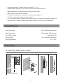
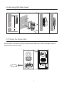
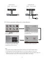
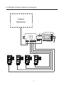
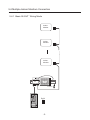
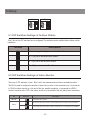
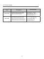
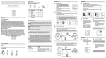
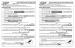
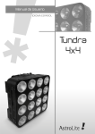
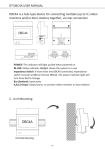
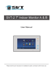
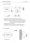
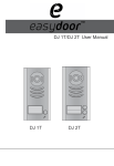
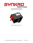
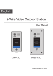
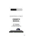
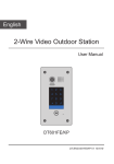
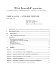
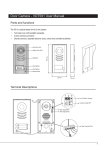
SVT-2 Outdoor Station B/C
User Manual
SVT-2 Outdoor Station A
2W12120
SVT-2 Outdoor Station B
2W12120
Please read this user manual prior to installing the system, and keep it well for future use.
CONTENTS
1.Parts and Functions............................................................................................. 1
2.Terminal Descriptions........................................................................................... 1
3.Specification ....................................................................................................... 2
4.Mounting............................................................................................................... 2
4.1 Mounting Without Rain Guard .......................................................................... 2
4.2 Mounting With Rain Guard ............................................................................ 3
4.3 Placing Name Label....................................................................................... 3
4.4 Adjusting Camera Angle................................................................................. 4
5.System Wiring and Connections.......................................................................... 4
5.1 Basic Connection........................................................................................... 4
5.2 Electric Lock Connection................................................................................ 5
5.2.1 Door Lock Controlled with Internal Power............................................. 5
5.2.2 Door Lock Controlled with Dry Contact................................................. 5
5.2.3 How to setup the unlock parameter in Monitor....................................... 6
5.3 Multi Outdoor Stations Connection................................................................ 7
5.4 Multi Indoor Monitors Connection ..................................................................... 8
5.4.1 Basic IN-OUT Wiring Mode.................................................................. 8
5.4.2 With DBC-4 Wiring Mode..................................................................... 9
6.Setup.................................................................................................................... 10
6.1 DIP Switches Settings of Outdoor Station. ....................................................... 10
6.2 DIP Switches Settings of Indoor Monitor .......................................................... 10
6.3 Power Supply.................................................................................................... 12
7.Cable Requirements ............................................................................................ 13
1.Parts and Functions
Camera Lens
Speaker
176 mm
Night View LED
Name Plate
Call Button
Microphone
Rain Guard
90 mm
23 mm
Note: Outdoor Station B has two call buttons.
2.Terminal Descriptions
1 2 3
ON
Outdoor Station Code DIP
1 2
ON
1 2
Lock Control Jumper
MIC adjustment
SPK adjustment
BUS
-1-
S2+ SPL S1+
Main Connection Port
••
••
Lock Control Jumper: To select the lock type: see 5.2.1 , 5.2.2
••
••
••
••
••
Main Connect Port: To connect the bus line and the electric locks.
Outdoor Station Code DIP: Total 4 outdoor stations can be supported,see 6.1
BUS: Connect to the bus line, no polarity.
PL: External lock power input, connect to the power positive(power +).
S1+, S2+: Lock power(+) output, to connect 2 locks.
S-: Lock power(-) output, connect to the power(-) input of locks(only when using the camera to
power the locks, if using the external power supply for the locks, the S- will not be connected).
3.Specification
Lock Power supply:
12Vdc, 300mA(Internal Power)
Power Consumtion:
1W in standby, 12W in working
NO, COM dry contact:
Max. 48V dc 1.5A
Unlocking time: 1 to 9 seconds, set by Monitor
Working temperature:
-10ºC ~ 45ºC
4.Mounting
4.1 Mounting Without Rain Guard
1
2
3
1
2
160-165cm
-2-
4
4.2 Mounting With Rain Guard
1
2
3
1
2
160-165cm
4.3 Placing the Name Label
ON
name label
-3-
1 2
Move the plastic cover away to open the transparent name label cover, insert a name paper, then put
the plastic cover back to the panel.
4
4.4 Adjusting the Camera Angle
Use a screwdriver to loose the screw and then adjust
the angle of the camera ,then fix the screw back to hold
the position of the camera.
5.System Wiring and Connections
5.1 Basic Connection
ON
1 2
AC~
SVT-2 PC6
L1 L2 PL S1+ S2+ S-
+
-4-
Indoor
Monitor
5.2 Electric Lock Connection
5.2.1 Door Lock Controlled with Internal Power
Note:
1.
Electric lock of Power-on-to-unlock type should be used.
2.
The door lock is limited to 12V, and holding current must be less than 250mA.
3.
The door lock control is not timed from Exit Button(EB).
4.
The Unlock Mode Parameter on the Indoor Monitor must be set to 0 (by default).
One (1) lock connection
Two (2) lock connection
Jumper position in 1-2
BUS
PL
S1+
S2+
Jumper position in 1-2
BUS
S-
*EB
PL
S1+
S2+
S-
2nd
* EB
2 nd
LOCK
LOCK
*EB
1ST
1 ST
LOCK
5.2.2 Door Lock Controlled with Dry Contact
Note:
1.
The external power supply must be used according to the lock.
2.
The jumper must be taken off before connecting.
3.
Setup the Unlock Mode on the Indoor Monitor for different lock types.
•• Power-on-to-unlock type:Unlock Mode=0 (by default)
•• Power-off-to-unlock type:Unlock Mode=1
-5-
connect one lock
connect two locks
Take off the Jumper
BUS
PL
S1+
S2+
Take off the Jumper
S-
BUS
POWER
SUPPLY
PL
S1+
S2+
S-
POWER
SUPPLY
LOCK
LOCK
LOCK
5.2.3 Unlock parameter setting (set on Indoor Monitor)
Manual
Monitor
Memory
Playback
Monitor
Album
? About
1.Touch
menu page.
Intercom
H/W :
S/W:
Local addr:
Unlock timing:
Video standard:
UI-CODE:
MCM-VER.:
Updated:
Multimedia
Close
User Setup
09/30/2014 Thu.16:41
--- a1.3
V17.11.418.00
-----------
2.Touch the screen anywhere
and hold for 2s.
item on main
Installation settings:
[0010]#:Remove all remote control
[0011]#:Add remote control
[8000]#:Set as master unit 0
[8001]#:Set as slaver unit 1
[8002]#:Set as slaver unit 2
[8003]#:Set as slaver unit 3
[8004]#:Set as guard unit
[8005]#:Set as not guard unit
[8006]#:Panel on as slaver unit called
[8007]#:Panel off as slaver unit called
[8008]#:Date format:MM/DD/YYYY
[8009]#:Date format:DD/MM/YYYY
[8010]#:Set lock mode to 0
[8011]#:Set lock mode to 1
[8021]~[8029]
#Set the lock time of 1~9s
Multi language settings:
---
Code Number:[----]
4
2
5
3
6
7
8
9
1
0
Installer
setup
Caliber
TouchScreen
Cancel
Home
4.A digital keypad and setting
instructions will be shown.
3.Touch Installer setup item
Note:
1.The system must be installed properly before proceding to the Unlock Parameter Setting.
2.The parameter will be saved automatically,so you only need to program on one monitor.
3.Please note, the text of the diagrams above may distinguish on each Indoor Monitor series. For
additional information, refer to the corresponding Indoor Monitor User Manual.
-6-
5.3 Multiple Outdoor Stations Connection
Indoor
Monitors
SVT-2
DBC4
SVT-2
DPS
SVT-2
PS5
A B C D
BUS
85~260VAC
ID=00
ON
ON
ON
1 2
L1 L2 PL S1+ S2+ S-
1# Camera
ID=10
ON
ON
1 2
ON
1 2
ON
12
L1 L2 PL S1+ S2+ S-
2# Camera
ID=01
ON
1 2
1 2
L1 L2 PL S1+ S2+ S-
1 2
3# Camera
ID=11
1 2
4# Camera
L1 L2 PL S1+ S2+ S-
-7-
5.4 Multiple Indoor Monitors Connection
5.4.1 Basic IN-OUT Wiring Mode
Indoor
Monitor
Indoor
Monitor
Indoor
Monitor
SVT-2
PS5
SVT-2
DPS
85~260AC
ID=00
ON
1 2
-8-
5.4.2 Using DBC-4 device - Wiring Mode
Indoor
Monitor
Indoor
Monitor
Indoor
Monitor
Indoor
Monitor
Indoor
Monitor
Indoor
Monitor
Indoor
Monitor
HI
OUT IN
Indoor
Monitor
A B C D
SVT-2
DBC-4
HI
OUT IN
A B C D
SVT-2
PS5
85~260AC
ID=00
ON
1 2
-9-
SVT-2
DBC-4
SVT-2
DPS
6.Setup
ON(1)
ON
=
OFF(0)
ON
=
6.1 DIP Switches Settings of Outdoor Station
Total 2 bits on the DIP switches can be configured.The switches can be modified either before or after
installation.
Bit state
Descriptions
ON
Default setting, ID = 0(00), set to the first Door Station.
1 2
ID = 1(10), set to the second Door Station.
ON
1 2
ON
ID = 2(01), set to the third Door Station.
1 2
ID = 3(11), set to the fourth Door Station.
ON
1 2
6.2 DIP Switches Settings of Indoor Monitor
There are 3 DIP switches in total. Bits 1 and 2 are reserved and must be on the default position.
The Bit 3 is used to configure the position of each indoor monitor in the connection line. It must be set
to ON if the indoor monitor is in the end of the line, parallel connection, or connected to a DBC-4
module. It must be set to OFF if the indoor monitor is in the middle of the line (daisy chain connection)
Bit
DIP1&2
DIP3
Bit State
1 2 3
Description
Reserved. left to default.
ON
1 2 3
ON
1 2 3
ON
Set to OFF. When the monitor is in the middle of the line in daisy chain connection.
Set to ON. When the montior is at the end of the line or connected to a SVT-DBC4.
-10-
Each indoor monitor should be assigned with an address in the system.
SVT-2 Outdoor Station B (2W12120): A maximum of 16 indoor monitors can be connected to the
system. Program the indoor monitors with user codes 0 - 15.
SVT-2 Outdoor Station C (2W12130): 16 indoor monitors can be connected to each call button, with
a maximum of 32 indoor monitors per system.
*For additional settings, refer to the Indoor Monitor User Manual.
Input No.
User Code
Input No.
User Code
Input No.
User Code
8200
Code=0
8211
Code=11
8222
Code=22
8201
Code=1
8212
Code=12
8223
Code=23
8202
Code=2
8213
Code=13
8224
Code=24
8203
Code=3
8214
Code=14
8225
Code=25
8204
Code=4
8215
Code=15
8226
Code=26
8205
Code=5
8216
Code=16
8227
Code=27
8206
Code=6
8217
Code=17
8228
Code=28
8207
Code=7
8218
Code=18
8229
Code=29
8208
Code=8
8219
Code=19
8230
Code=30
8209
Code=9
8220
Code=20
8231
Code=31
8210
Code=10
8221
Code=21
B
A
Note:
Call button A: configure indoor monitors with user codes 0 - 15
Call button B: confugure indoor monitors with user codes 16 - 31
A
-11-
6.3 Power Supply
Name
SVT-2 PC6
SVT-PS5
Description
Specifications
It supplies power for the outdoor stations,
indoor monitors and other accessories. It
supports up to 8 indoor monitors.
Input Voltage: 100 ~ 240Vac
Input Frequency: 50 ~ 60Hz
Rated Output Voltage: DC 28V, 2V
Rated Output Current: 1.5A
It provides power for the outdoor stations,
indoor monitors and other accessories. It
supports a maximum of 32 indoor monitors. It
must be used along with a SVT-DPS device.
Input Voltage: 100~120VAC (2.5A),
200 ~ 240VAC (1.5A)
Input Frequency: 50 ~ 60 Hz
Rated Output Voltage: 24Vdc
Rated Output Current: 4.5A
-12-
7.Cable Requirements
Using different cables may also affect the maximum distance which the system can reach.
The farest monitor
Indoor
Monitor
with two or four monitors
Indoor
Monitor
Indoor
Monitor
DBC/DBC-4
B
C
When Monitor quantity < 20
SVT-2
DPS
Cable Usage
A
B
CAT5 cable (1 pair of wire per
conductor - must solder the ends)
14 AWG Speaker Wire
(Stranded non-shielded)
200 feet
60 meters
200 feet
60 meters
100 feet
30 meters
260 feet
80 meters
260 feet
80 meters
130 feet
40 meters
C
When Monitor quantity > 20
Cable Usage
14 AWG Speaker Wire
(Stranded non-shielded)
A
230 feet
70 meters
SVT-2
PS5
B
C
165 feet
50 meters
100 feet
30 meters
-13-
A
The design and specifications of this user manual can be changed without any notification to the user.
All copyright and interpretation rights are reserved to SVT Innovations Inc.