1
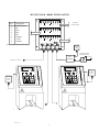
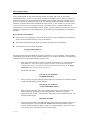
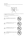
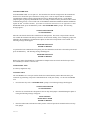
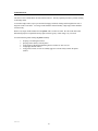
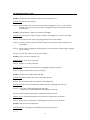
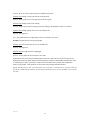
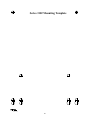
SERIES 3102 ACCU-TOUCH®2 TIME AND DATA COLLECTION TERMINAL Accu-Time Systems, Inc. 420 Somers Road, Ellington, CT 06029 Tel: (860) 870-5000 Fax: (860) 872-1511 Web Site: www.accu-time.com Copyright 2000 Accu-Time Systems, Inc. Accu-Time is a registered trademark of Accu-Time Systems, Inc. The material contained in this manual is subject to change. No part of this manual may be reproduced or distributed in any form or by any means, or stored in any database or retrieval system, without AccuTime’s prior written permission. Accu-Time Systems, Inc. makes no warranty of any kind including, but not limited to, and implied warrantees of merchantability, and fitness for a particular purpose in regard to this manual. All Rights Reserved. Printed in the USA. ACCU-TIME SERIES 3102 TABLE OF CONTENTS Introduction Theory of Operation Features Specifications 1 2 3 4 Installation Test Enrollment 5 8 ACCU-RATE Diagnostics Maintenance Troubleshooting Guide 11 16 17 MANU3102-01 INTRODUCTION The Accu-Time Series 3102 Accu-Touch®2 is a biometric, personal identification line of time and data collection terminals, which utilizes a dual peg platen for a quick and accurate verification. Open ACCUTECTURE, “C” programmable and feature-rich, the Series 3102 is ideally suited for small or large employee based companies. Among the many features of the Series 3102 are: ! Multi-Media: Multiple cues, audio and visual, assist the user in the operation of the terminals. The Accu-Touch®2 three-dimensional finger geometry is a highly accurate and easy to use personal identification or verification product. ! Flexibility: The Series 3102 works equally well with the right or left hand and also has an optional badge reader, making the device highly versatile. The terminal can act as a standalone time station or as part of a local or wide area network. The ability to interface with virtually any host hardware or software platform gives the device a large range of communication possibilities. ! Custom Applications: Custom programs and programmable function keys can provide users with the flexibility to create a variety of options. ! Reliability: A Real Time Clock (RTC) provides 12 or 24 hour time formats with quartz precision. An optional non-interruptible power supply (UPS) provides terminal during power outages (up to 1.5 hours). Data storage will be preserved for up to 4 days with the memory backup system. ! Durability: The environmental enclosure protects circuitry from environmental conditions such as extreme temperatures and airborne dust. The terminal contains no moving parts and is housed behind a tough, environmentally resistant casing. Versatility, Reliability and Affordability in a state-of-the-art ergonomically designed terminal and backed by the ACCU-TEAM. 1 MANU3102-01 THEORY OF OPERATION The basic premise of the Series 3102 is to capture and store the geometric characteristics of the first and second finger on the right or left hand. Although not required, the first two fingers of either hand are recommended for ease of use. This process is done to ensure proper and precise identification of an individual in a time and data collection environment. In order to accomplish this task, a critical function must occur; enrollment. In general terms, enrollment is the process used to capture and preserve the biometrics two finger image as a data template, which will later be used in the verification process. In order to capture the threedimensional finger geometry during the enrollment, ATS incorporates the use of a dual pegged platen, opto-electronics, and electronic camera. This process automatically stores the information as a data template. To begin the enrollment process, the user first makes a primary identification claim by entering a personal identification number (PIN) by way of the keypad or swiping a card through a reader. The first and second fingers (recommended) are placed on either side of the two pegs and “photographed” three different times, removing and replacing the fingers each of the 3 times. The three dimensional image is captured and integrated with the PIN number, accelerating the identification process. The PIN and finger transaction must both be accomplished for a positive read even after enrollment. The enrollment template (finger geometry) may be stored inside the terminal, transferred to other terminals or uploaded to a host. Template Updating The user’s finger data is modified and the template updated every time a successful transaction is completed (application dependent). The Series 3102 Accu-Touch®2 is designed to track and update finger positioning and gradual alterations in finger shape that accompany aging, weight gain or loss, etc. MANU3102-01 2 FEATURES • Single or multi-clock environments on a variety of host platforms with application programs integrating the ATS DATA TRAKER family of modules. • 128K byte capacitor back memory base • EIA Standard RS232 or RS485 compatible. • Up to 9600-baud modem operation • On-board ACCU-RATE terminal set-up and diagnostics package. • Custom keypad legends with software defined function keys • Large 20 key tactile 4x5 matrix keypad • Audible annunciator • 2 or 4 line x 20 Character liquid crystal backlit display • Integrated or External Bar Code readers • Magnetic slot readers • Individual user thresholds, automatic template updating, auto-recalibration • DI/DO port for access control • Optional printer port • Low voltage power source locally or remotely supplied (consult factory for remote power) • Die cast aluminum housing with steel key-lockable, tamper resistant base assembly • FCC part 15 and CE Certified MANU3102-01 3 SPECIFICATIONS Display: 2 line x 20-character backlit super-twist LCD 4 line x 20-character backlit super-twist LCD Clock: 12 or 24 hour-format-USA or International (quartz precision) Time stamp of data transactions Indicators: Yellow LED Low Power indicator Two programmable LED indicators, RED and GREEN Six Red LED position indicators in pyramid form for finger positioning Memory: 128K Byte of capacitor backed memory (I.e. 300-employee base-program dependent) Programming: ATS DATA TRAKER modules, “C” programming language or third party custom application packages. Interface: EIA Standard RS232 or RS485 (2 or 4 wire) Standard AT command set for up to 9600-Baud internal Modem operation Dual DI/DO or Serial Interface Printer port Enclosure: Die cast aluminum housing with steel key-lockable base assembly Power: Regulated 12VDC @ 2 ½ amps Local, remote or centrally powered (consult factory for remote or central power) Non-interruptible power source with charger (optional) Environment: Operation: 32° to 110° F (0° to 43° C) Certification: FCC part 15 and CE certified Physical: 7.09” Length x 7.42” Width x 12.02” Height. Weight: 9.16 Lbs. (18.01cm length x 18.85cm width x 30.53cm height. Weight: 4.15kg) Accessories: Integrated or External Optical Bar Code slot readers Integrated magnetic slot readers Digital Bar Code Wands Solid State or Dry Contact relay modules Serial Interface Printer Port MANU3102-01 4 INSTALLATION GENERAL INSTALLATION GUIDELINES Environment Although the Series 3102 Time and Data Collection Terminal is a durable industrial-grade device, which will endure harsh environments, it never the less is an electronic device. Environmental constraints exist and care should be given when selecting a location for installing and operating the Series 3102. The ATS terminal is designed to operate indoors. Exposure to outdoor elements such as rain or snow will not only void the manufacturer warranty, but may cause damage to the device. Select a location, which has adequate lighting and accessibility to operate the terminal safely. Operating parameters Accu-Time recommends that the Series 3102 operate in an ambient temperature range of between 32° and 110° Fahrenheit. Non-condensing humidity should be less than 95%. The terminal should be mounted on a vibration free area. The back-plate should be mounted vertical, with the platen approximately 43 inches from floor to terminal. The RS232 Series 3102 must be located no greater than fifty (50) wire-feet from the host computer. EIA standards for RS232 protocol data transmission dictate this cable distance. Exceeding this requirement greatly increases the chances for continual data re-transmission, which may never be acknowledged. The RS485 Series 3102 locally powered must be located no greater than five thousand (5000) wire-feet from the host computer. EIA standards for RS485 protocol data transmission dictate this cable distance. Base Locate a flat wall surface to accommodate the Series 3102. Unlock and remove the top cover from the base. The bottom keyholes should be installed into the wall first and then the top holes. A mounting template is provided on the last page of this manual. With terminal power being supplied locally, insure that a conventional 110VAC-wall outlet, 220VAC in Europe and other areas, (check local electrical code requirements) is available to accept the Series 3102 12VDC power pack assembly. The outlet should be no further than four-(4) feet from the terminal. MANU3102-01 5 For RS232 communication applications, one end of the communication cable terminates into the Series 3102 communication port while the other terminates into the host computer’s serial port via an ATS RS232 Communication Adapter. For remote powering, consult factory. RS232 INSTALLATION 12 VDC POWER SUPPLY Pin # 1 2 3 4 5 6 7 8 ENROLL Description Earth Ground Receive Transmit N/C N/C Ground +VDC Ground NOTE: Pinouts are referenced to the terminal TO HOST COMM ADAPTER DB25-RJ45 W/PWR For RS485 communication applications, ATS recommends using a data transmission cable that adheres to the following specifications: Five conductor shielded 24-gage wire with a drain. The impedance of the cable should be 100 Ohms. The capacitance should be 12 pico-farads per foot. The jacket of the cable is typically either PVC or Plenum material. (*NOTE* If the host is not equipped with an RS485 port, an ATS RS232/485 Converter with 12 volt power pack assembly will convert the terminal communication lines to RS232 levels. The host output of the RS232/485 Converter plugs directly into the ATS RS232 Communication Adapter.) RS485 allows for the Series 3102 to be used in multi-dropped networks. Thirty-two (32) terminals can be supported on a single host communication port. The use of ATS Series 1000 Network Controllers allow up to 256 terminals on a single host communication port. MANU3102-01 6 MULTI-CLOCK - RS485 INSTALLATION 1 3 4 5 6 E.GND CO M M 1 2 3 5 4 6 7 8 P.GND 5 P.GND 4 +VDC 3 +VDC 2 1 6 7 8 Trunk Wire Network Cabling P.GND +VDC P.GND E.GND COMM 8 P.GND CO M M 7 P.GND Description Earth Ground DI DO + DO DI + Ground +VDC Ground E.GND Pin # 1 2 3 4 5 6 7 8 2 DC PO W E R JP2 JP1 NOTE: Pinouts are referenced to the terminal NC JP3 D RO P 1 JP4 NC NO DR OP 3 D RO P 2 D RO P 4 NO 12 VDC POWER SUPPLY E.G N D COMM ADAPTER DB25-RJ45 W/PWR RS-232 TO RS-485 CONVERTER TO HOST NETWORK CONTINUED 12 VDC POWER SUPPLY ENROLL ENROLL 12 VDC POWER SUPPLY MANU3102-01 7 TEST ENROLLMENT ATS recommends that the first and second fingers of the same hand, right or left, be successfully “photographed” three (3) times to create the data template for enrollment. Remove and insert fingers for each of the 3 pictures. The three dimensional enrollment of the two fingers onto a data template is one of the most critical aspects of the Series 3102 set-up. The following detailed enrollment procedure must be adhered to if consistent and accurate enrollments are to be assured. Actual enrollment is performed in the on-line or USE mode with each template matching a defined PIN number. This PIN number may be entered into the Series 3102 via the badge reader or keypad. Since the enrollment procedure may vary from application to application, the following approaches the enrollment process utilizing the ACCU-RATE test mode. ACCU-RATE Test Enrollment: ▲ Place the Series 3102 TEST/USE switch in the TEST position. (Switch designations are described in detail in the ACCU-RATE™ Set-up section of this manual.) ▲ The terminal will run through the power up sequence and display ATS TEST MODE. ▲ Press the Enter key. The terminal will display: ATS TEST MODE XXX YY -----------------------------------The display shows ATS TEST MODE on the top line followed by two sets of numbers. The first number (XXX) indicates the amount of memory installed (in Kilobytes). The right most number (YY) indicates the terminal’s Real Time Clock incrementing in seconds (00-59). ! Enter in the following number sequence to begin the enrollment process: 3554649 followed by the Enter key. Note: The first finger sample enrolled is the most important and will contribute most heavily to the quality of the total enrollment process. (Refer to the Finger Positioning section for proper finger placement.) ! The terminal will display: PLEASE PLACE FINGERS FOR ENROLLMENT ! If the two fingers were placed upon the platen within (18) seconds the six red LEDs will flash and the following message will be displayed: PLEASE PLACE FINGERS AGAIN FOR ENROLLMENT ! Remove and present fingers again, as the terminal will require two more placements. The following message will appear for each of the placements. This process will take approximately four seconds. At this point, the fingers may be removed from the platen. The terminal will then display: PRESENT FINGERS ! A small inverted pyramid of red LEDs will light, signifying that the terminal is ready to read. Present the fingers to verify the enrollment. NOTE: After the terminal reads the fingers correctly, all the red LEDs will flash once and a score will be displayed. The closer to 0 the score, the better the verification of the test enrolled template. MANU3102-01 8 Finger positioning: Finger positioning should be done with careful attention to the pyramid of red LEDs located below the keypad assembly. Correct finger placement: Figure 1. ▲ The index and middle fingers (recommended) should be placed flat on the platen, straddling/touching the pegs. ▲ Fold the thumb around the third and fourth fingers. ▲ The base between the two fingers should be touching the smaller front peg. The red LED indicators: If the top red light is activated, this indicates that the two fingers are too deep on the platen. Pull back a bit. If the left light in the second row is illuminated, the right finger is touching the pegs but the left is not. If the right light in the second row of LEDs is lit, the left finger is touching the pegs but the right is not. If the middle light in the last row of LEDs is lit, the fingers are not deep enough on the platen. Slide fingers towards the back of the platen. MANU3102-01 9 If the left outside light in the last row is activated, ensure that the hand is straight and not off to the left. The first and second fingers should be the only ones touching the platen. If the right outside light in the last row of the pyramid is activated, ensure that the hand is straight and not off to the right. The first and second fingers should be the only ones touching the platen. MANU3102-01 10 ACCU-RATE SET-UP AND DIAGNOSTICS POWER UP To power up the Series 3102, a 12VDC at 2½ amp source must be applied to the terminal power jack. The Series 3102, with the TEST/USE switch placed in the USE mode, beeps, executes a power up sequence and displays the message “TERMINAL LOCKED”. ACCESSING TEST MODE To access the test mode: 1) Unlock the terminal face from the base assembly on the Series 3102. 2) To locate the TEST/USE switch on the I/O board assembly, slide the terminal face straight out from the base being careful not to unplug the ribbon cables. 3) The switch is under the 20-position ribbon cable located in the bottom corner of the terminal cover. Slide the switch away from the ribbon cable to enter the TEST position. 4) Reattach the faceplate to the base. The Series 3102 displays “ATS TEST MODE”. 5) By pressing the CLEAR key, the user can step through the selections. (*NOTE* Test mode may be exited at any time by placing the TEST/USE switch back to the USE position and pressing the CLEAR key.) SELECTIONS: ! ATS TEST MODE: Tests the Keypad, Display, Memory, Real Time Clock, Bar Code/Magnetic slot reader, and Bar Code Wand circuitry. ! ATS SET-UP MODE: Configures the communication parameters—Baud Rate, Parity Bit, Terminal Address, and Terminal Application Type. ! ATS NETWORK TEST: Performs a terminal to host communication loop-back test. Verifies integrity of cabling. ! ATS BATTERY TEST: For factory diagnostics only. ! ATS DI-DO TEST: Checks the Digital Input/Digital Output auxiliary port by performing a loop-back test. ! ATS RESTART MODE: Resets the terminal, clears all data from memory and performs a power-up sequence. ! ATS AUX PORT TEST: For factory diagnostics only. MANU3102-01 11 ATS TEST MODE ATS TEST MODE checks the functionality of the terminal Keypad, Memory, Real Time Clock, Bar Code/Magnetic slot reader, and Bar Code Wand circuitry. To enter the TEST MODE, press the ENTER key. The message “ATS TEST MODE” appears on the top line of the display. The 2nd line of the display indicates the two program (EPROM) numbers. By pressing the ENTER key the following information appears. ATS TEST MODE (XXX) (YY) ----------------------The terminal displays ATS TEST MODE on the top line followed by two sets of numbers. The first number (XXX) indicates the amount of memory installed (in Kilobytes). The right most number (YY) indicates the terminal Real Time Clock incrementing in seconds (00-59). Testing the Keypad At this time the user may test the keypad assembly. Each time a key is pressed the terminal will beep and the key value will appear on the 2nd line of the display. Press the ENTER key. The message “KEY INPUT ACCEPTED” is displayed. Each time the ENTER key is pressed an internal test of the terminal communication port is performed. If an error is detected the message “COMM PORT FAIL” will display, the invalid light will flash and the negative acknowledgement beeper tone will cycle. This message will continue until power is removed from the terminal. Refer to the Troubleshooting Section of this manual. Testing the Badge Reader ATS TEST MODE accepts inputs from slot readers (optical or magnetic) and bar code wands. To test the reader, simply swipe the applicable media. The terminal beeps and displays the badge data. To test the bar code wand, the user lightly drags the tip of the wand across the bar code badge or label. The wand should be positioned in the hand (similar to that of a pen or pencil) at an approximate 30° angle. Begin the scanning process by dragging the wand horizontally, in a straight line, and at a constant speed across the entire label area. Each bar code label includes a preceding and trailing ¼ inch quiet zone. This area, which is free of any marks or bars, is a part of the bar code label and must be included when scanning the label. Upon the successful completion of a bar code read, the terminal will beep and display the data. To proceed to the ATS SETUP MODE press the CLEAR key. ATS SETUP MODE ATS SETUP MODE allows the operator to configure the terminal for communications with the host computer. The Series 3102 default parameters are set as follows: Baud Rate Parity Address Terminal Application Type 9600 ODD 01 A To enter the ATS SETUP MODE, press the ENTER key at the “ATS SETUP MODE” display prompt. (Prior to pressing the ENTER key the 2nd line of the display will indicate the current terminal setup values.) MANU3102-01 12 Baud Rate To change the terminal baud rate: 1. Press CLEAR to step through the baud rate choices: 19200 9600 4800 2400 1200 M1200 (Not applicable) M2400 (Not applicable) 2. When the desired baud rate is displayed, press the ENTER key to store the value and advance to the next parameter. NOTE: Because an external modem is installed, it is suggested that no modem baud rate be selected. The modem self test will automatically fail. Parity To change the parity: 1. Press the CLEAR key to step through the parity choices: ODD EVEN NONE 2. When the desired parity is displayed, press the ENTER key to store the value and advance to the next parameter. Address To change the terminal address: 1. Press the CLEAR key to increment the address values form 01 to 32. 2. When the desired address is displayed, press the ENTER key to store the value and advance to the next parameter. Terminal Application Type The Terminal Application Type is used as a delimiter by the host for routing application information to the terminal. (Example-an access control terminal could have a different terminal type than a time and attendance terminal.) To change the terminal application type: 1. Press the CLEAR key to increment the type from A to J. 2. When the desired type is displayed, press the ENTER key to store the value and advance to the ATS NETWORK TEST. MANU3102-01 13 ATS NETWORK TEST ATS NETWORK TEST is a two-part test. The first allows the network wiring between the terminal and the host to be checked for open connections or wiring errors. This test requires that the ATS RS232 Communication Adapter, which is plugged into the host, be unplugged and pins 2 & 3 of the adapter jumped together (a paper clip should do the trick). Secondly, a local test can be performed on the terminal communication circuitry. This test will work for both RS232 and RS485 installations (RS485 installations require an ATS 232/485 Converter). If a modem is installed the Network Test is not applicable. To enter NETWORK TEST, press the ENTER key at the “ATS NETWORK TEST” prompt. The following message appears: SWITCH TEST SWITCH TO USE POSITION Place the switch on the back of the terminal into the USE position. The Series 3102 performs a network test in which the terminal sends data up to the host, via the network cabling. Since a temporary jumper was installed in the ATS RS232 Communication Adapter, the data will be looped back to the terminal. The following message should appear: NETWORK TEST PASS ENTER TO RETEST To perform the local communication loop back, place the USE/TEST switch back to the TEST position and press the ENTER key. The following message should appear: NETWORK TEST PASS ENTER TO RETEST Remove the jumper from the RS232 Communication Adapter and secure it back into the host port. Press the CLEAR key to advance to the next test. ATS BATTERY TEST (For factory diagnostics only) ATS DI/DO TEST The ATS DI/DO Test is a two-part test that checks the terminal auxiliary DATA IN/DATA OUT port connection by performing a loop back communication test on the port circuitry. To enter the ATS DI/DO Test: 1. Press the Enter key at the “ATS DI-DO TEST” prompt. The following message should appear: SWITCH TEST SWITCH TO USE POSITION 2. Place the test switch into the USE position. Since no loop back jumper is installed during this phase of testing the following message will appear: DI-DO TESTING DI-DO TEST FAILED ENTER TO RETEST 3. Place the TEST/USE switch into the TEST position. This will provide the terminal with its own loop back jumper. MANU3102-01 14 4. Press the ENTER key. The following message should appear: DI-DO TEST PASSED ENTER TO RETEST 5. Press the CLEAR key to advance to ATS RESTART MODE. ATS RESTART MODE The ATS RESTART MODE clears all transaction data and any download from memory. To restart the terminal: 1. Press the ENTER key to select the ATS RESTART MODE. The terminal displays: PRESS ENTER TO CLEAR ALL TRANSACTION DATA 2. Press the ENTER key. The terminal displays: CLEAR FOR CYCLE TEST (Note: Cycle test is for factory diagnostics only) ENTER FOR RESTART 3. Press the ENTER key. The terminal displays: CLEARING MEMORY. . . The green Valid LED will blink and the terminal will execute a power up sequence and return the terminal back to the beginning of the Test Mode. ATS AUX PORT TEST (For factory diagnostics only) To exit the Test Mode, place the TEST/USE switch to the USE position and press the CLEAR key. The terminal will execute a power up sequence and display: “TERMINAL LOCKED”. The terminal can now accept a host download. This completes the ACCU-RATE test and set-up. Downloading the Series 3102 The Series 3102 terminal, when used with the standard Time and Attendance "C" application, can be downloaded with employee names, badge numbers, and schedules. These download commands and others are explained in the ATS DATA TRAKER command set manual. For further information refer to this manual. MANU3102-01 15 MAINTENANCE The Series 3102 is a maintenance-free data collection device. The only required procedure is periodic cleaning of the badge reader. To clean the badge reader, swipe a pre-moistened (Isopropyl Alcohol) cleaning card through the bar code or magnetic reader several times. Low usage readers should be cleaned monthly. High usage readers should be cleaned weekly. Remove any finger marks and dust from the platen with a soft lint-free cloth. Wet the cloth with a mild dishwashing liquid or comparable and wipe platen surfaces gently. Polish using a dry, soft cloth. Avoid the following when cleaning the platen assembly: ! ! ! ! ! Scraping or scratching the surfaces Spraying cleaner directly onto the platen Using cleaners containing ammoniating abrasive cleaners or steel wool, etc. Using highly alkaline cleaners Using petrol, benzene, acetone or similarly aggressive solvents likely to attack the plastic surfaces. MANU3102-01 16 TROUBLESHOOTING GUIDE Problem: Terminal does not power up and none of the status LEDs are lit. Possible cause: No DC power applied Solution: Ensure primary side of DC power pack assembly is plugged into a live AC outlet. Ensure secondary side of DC power pack assembly is plugged into the Time and Data Collection Terminal (DCT). Problem: Terminal display is blank (no characters or backlight). Possible cause: The primary of the power pack assembly is not plugged into a 110VAC-wall outlet. Solution: Verify that the power cable is fully plugged into the back of the terminal. Solution: If remotely powered, check cable distance and any network power jumpers that may need repositioning. Solution: Test the outlet by plugging in another appliance or check that the secondary supply is plugged into the terminal. Solution: If all else fails, replace the power pack assembly. Problem: Yellow Low Power indicator is lit. Possible cause: Low DC power is attached. Solution: Replace 12-volt DC power pack. Possible cause: Terminal does not go blank after unplugging the battery connector. Solution: Unplug and replace the power pack assembly. Problem: Terminal is not communicating with Host. Possible cause: HOST TEST/USE switch is in the TEST position Solution: Place the HOST TEST/USE switch is in the USE position. Possible cause: DCT to Host communication cable is defective or unplugged on either end. Solution: Verify cable is tested and plugged into both ends. (Ensure cable termination guidelines and lengths are observed.) Solution: Ensure the application package is loaded and running on the host. Possible cause: Communication parameters for the DCT do not match those of the Host. Solution: Refer to the ACCU-RATE test and diagnostics section for set-up directions. Problem: DCT does not accept badge data. Possible cause: Bar code badge is not manufactured to proper specification. MANU3102-01 17 Solution: Refer to vendor’s specifications for manufacturing criteria. Possible cause: Badge is being swiped in the wrong direction. Solution: Ensure media faces to the right (away from the keypad). Possible cause: Badge reader needs cleaning. Solution: Swipe a pre-moistened (isopropyl alcohol) cleaning card through the reader several times. Possible cause: Badge number does not exist in validation file. Solution: See Supervisor Note: If all solutions fail try reading badge in the ACCU-RATE test mode. Problem: Terminal does not accept keypad input. Possible cause: Keyed data does not exist in validation file Solution: See Supervisor Possible cause: Keypad connector is unplugged. Solution: Test keypad in the ACCU-RATE test mode. If all solutions have been explored and the problem still exists, contact the Accu-Time Product Service Department at (860) 870-5000 during normal working hours 9 AM to 5 PM- Monday through Friday. Prior to contacting Accu-Time, please have available the serial number and, if possible, the configuration number of the product. These numbers can be located on the terminal identification label. NOTE: The DCT has no user serviceable parts. The Accu-Time terminal must be operated within the parameters included in this manual. Any operation performed contrary to these parameters will void the warranty. MANU3102-01 18 FCC Statement This equipment has been tested and found to comply with the limits for a Class A digital device pursuant to Part 15 of the FCC rules. These limits are designed to provide reasonable protection against harmful interference in a residential installation. This equipment generates, uses, and can radiate radio frequency energy and, if not installed and used in accordance with the instructions, may cause harmful interference to radio communications. However, there is no guarantee that interference will not occur in a particular installation. If this equipment does cause harmful interference to radio or television reception, which can be determined by turning the equipment off and on, the user is encouraged to try to correct the interference by one or more of the following measures: * * * Reorient or relocate the receiving antenna. Increase the distance between the time clock and the receiver. Connect the equipment into an outlet on a circuit different from that which the receiver is connected. FCC Warning: To assure continued FCC emission limit compliance, the user must use only the recommended shielded interfacing cable when connecting to a host computer. Also, any unauthorized changes or modifications to this equipment would void the user authority to operate this device. MANU3102-01 19 Series 3102 Mounting Template MANU3102-01 20