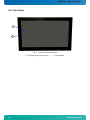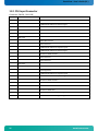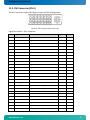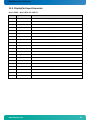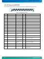
1
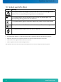
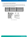
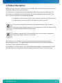
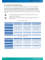
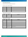
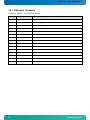
OmniView HMI-OV215/-OV185/-OV156 User’s Guide (Version 1) 0-0096-22514 If it’s embedded, it’s Kontron OmniView–User’s Guide (V1) Table of Contents 1. Introduction ................................................................3 1.1. Symbols used in this Guide ................................................4 2. Important Instructions ......................................................5 2.1. Note on the Warranty ......................................................5 2.2. Exclusion of Accident Liability Obligation ................................5 2.3. Liability Limitation / Exemption from the Warranty Obligation .............5 3. General Safety Instructions for IT Equipment ................................6 3.1. Electrostatic Discharge (ESD) .............................................7 3.1.1. Grounding Methods .....................................................7 4. Electromagnetic Compatibility (Class A Device) ..............................8 4.1. Electromagnetic Compatibility (EU) ........................................8 4.2. FCC Statement (USA) .......................................................8 4.3. EMC Compliance (Canada) ...................................................8 5. Scope of Delivery ...........................................................9 5.1. Optional Parts ............................................................9 5.2. Type Label and Product Identification ....................................10 6. Product Description ........................................................11 6.1. OmniView Touch Monitor Base ..............................................12 6.2. Product Images OmniView 21.5” AC PSU (other units similar) ...............13 6.3. Front View ...............................................................14 6.3.1. Display with Touch Screen ............................................15 6.3.2. Front Plate ..........................................................15 6.3.3. Calibrating the Touch Screen .........................................15 6.3.4. Power and Grounding ..................................................16 6.3.5. Interfaces ...........................................................17 6.4. I/O Panel View ...........................................................18 6.5. Rear Side ................................................................19 7. Installation Instructions ..................................................20 8. Maintenance and Prevention .................................................21 8.1. Touch Screen Care and Cleaning ...........................................21 9. Technical Data .............................................................22 9.1. Electrical Specifications ................................................22 9.2. Mechanical Specifications ................................................23 9.3. Environmental Specifications .............................................23 10. Regulatory and Certification Information...................................24 10.1. Product Regulatory Compliance ...........................................24 10.1.1. Product Safety Compliance ...........................................24 10.1.2. Product EMC Compliance – Class A Compliance .........................24 10.1.3. Certifications/Registrations/Declarations ...........................24 11. Technical Appendix - Interfaces............................................25 11.1. Power Connector – DC Power Supply .......................................25 11.2. DVI Input Connector .....................................................26 11.3. DVI Connector (DVI-I) ...................................................27 11.4. DisplayPort Input Connector .............................................29 11.5. DP Connectors (DP0/DP1) .................................................30 11.6. Power Connectors ........................................................31 11.7. VGA Input Connector .....................................................32 www.kontron.com 1 OmniView – User’s Guide (V1.) 12. Technical Support ......................................................... 33 12.1. Returning Defective Merchandise ........................................ 33 2 www.kontron.com OmniView–User’s Guide (V1) 1. Introduction The information contained in this manual may be subject to technical alteration, particularly as a result of the constant upgrading of Kontron products. The attached documentation does not entail any guarantee on the part of Kontron with respect to technical processes described in the manual or any product characteristics set out in the manual. Kontron does not accept liability for printing errors or other inaccuracies in the manual unless it can be proven that Kontron is aware of such errors or inaccuracies or that Kontron is unaware of these as a result of gross negligence and Kontron has failed to eliminate these errors or inaccuracies for this reason. Kontron expressly informs the user that this manual only contains a general description of technical processes and instructions which may not be applicable in every individual case. In cases of doubt, please contact Kontron. This manual is protected by copyright. All rights are reserved by Kontron. Copies of all or part of this manual or translations into a different language may only be made with the prior written consent of Kontron. Kontron points out that the information contained in this manual is constantly being updated in line with the technical alterations and improvements made by Kontron to the products and thus this manual only reflects the technical status of the products by Kontron at the time of printing. © 2014 by Kontron Printing and duplication, even of sections, is only permissible with the express approval of Kontron. Kontron 14118 Stowe Drive Poway, CA 92064-7147 www.kontron.com 3 OmniView – User’s Guide (V1.) 1.1. Symbols used in this Guide Symbol Meaning This symbol indicates the danger of injury to the user or the risk of damage to the product if the corresponding warning notices are not observed. This symbol indicates that the product or parts thereof may be damaged if the corresponding warning notices are not observed. This symbol indicates general information about the product and the user manual. This symbol indicates detailed information about the specific product configuration. This symbol precedes helpful hints and tips for daily use. ® Microsoft, MS-DOS, Windows 7, Windows 8 and Windows NT are registered trademarks of the Microsoft Corporation. ® IBM, PC-AT, OS/2 and PS/2 are registered trademarks of the International Business Machines Corporation. ® Intel and Pentium are registered trademarks of Intel Corporation. ® AMI is a registered trademark of American Megatrends, Inc. Other product names cited in this manual may also be trademarks and are used here solely for identification purposes. 4 www.kontron.com OmniView–User’s Guide (V1) 2. Important Instructions This chapter contains safety instructions which must be observed when using the OmniView. The manufacturer’s instructions provide useful information on your OmniView. 2.1. Note on the Warranty Due to their limited service life, parts which by their nature are subject to a particularly high degree of wear (wearing parts) are excluded from the warranty beyond that provided by law. This applies to batteries and to the display backlighting, for example. 2.2. Exclusion of Accident Liability Obligation Kontron shall be exempted from the statutory accident liability obligation if the user fails to observe the safety instructions. 2.3. Liability Limitation / Exemption from the Warranty Obligation In the event of damage to the device caused by failure to observe the hints in this manual and eventually on the device Kontron shall not be required to honor the warranty even during the warranty period and shall be exempted from the statutory accident liability obligation. www.kontron.com 5 OmniView – User’s Guide (V1.) 3. General Safety Instructions for IT Equipment Please read this chapter carefully and observe the instructions for your own safety and to ensure correct use of the device. The chapter also contains information on approval and interference suppression of your device. The device has been built and tested by Kontron in accordance with UL/IEC 60950-1 and left the premises in a perfectly safe condition. In order to maintain the safe condition and ensure safe operation, the user must observe the instructions and warnings on the device and in the manual. The device must be used in accordance with the instructions for use. The electrical installations in the room must correspond to the requirements of the local (country-specific) regulations. Take care that there are no cables, particularly power cables, in areas where persons can trip over them. Do not use a power cable in sockets shared by a number of other power consumers. Do not use an extension cable. For DC power connection: The unit is only completely disconnected from the DC main power source, when the DC power cord is disconnected either from the power source or the unit. Therefore, the DC power cord and its connectors must always remain easily accessible. Do not place the device in direct sunlight, near heat sources, or in a damp place. Make sure the device has adequate ventilation. Only devices and components which fulfill the requirements of an SELV circuit (safety extra low voltage) in accordance with UL/IEC 60950-1 may be connected to the interfaces of the system. All plugs on the connection cables must be screwed or locked to the housing wherever possible. The device is designed to be mounted and operated only in the position described in this document. The proper mounting is a vertical (or close to) position with the interfaces downwards. This device generates heat during operation. Make sure it is adequately ventilated. Do not cover the ventilation holes in the display housing. Maintenance or repair on the open device may only be done by qualified personnel authorized by Kontron, who is aware of the associated dangers. The device has no components internally that requires access or any set up by Kontron personnel. If the unit malfunctions or a situation is encountered that requires that the unit be opened, then return to Kontron for maintenance. Only approved original accessories (optional parts) approved by Kontron may be used. 6 www.kontron.com OmniView–User’s Guide (V1) The DC-input must fulfill SELV requirements of UL/IEC 60950-1 standard. Safe operation is no longer possible when: o the device has visible damage o the device no longer functions In these cases the device must be shut down and secured against unintentional operation. 3.1. Electrostatic Discharge (ESD) A sudden discharge of electrostatic electricity can destroy static-sensitive devices or micro-circuitry. Therefore proper packaging and grounding techniques are necessary precautions to prevent damage. Always take the following precautions: 1. Transport boards in ESD-safe containers such as boxes or bags. 2. Keep electrostatic sensitive parts in their containers until they arrive at the ESD-safe workplace. 3. Always be properly grounded when touching a sensitive board, component, or assembly. 4. Store electrostatic-sensitive boards in protective packaging or on antistatic mats. 3.1.1. Grounding Methods By adhering to the guidelines below, electrostatic damage to the device can be avoided: 1. Cover workstations with approved antistatic material. Always wear a wrist strap connected to workplace. Always use properly grounded tools and equipment. 2. Use antistatic mats, heel straps, or air ionizers for more protection. 3. Always handle electrostatically sensitive components by their edge or by their casing. 4. Avoid contact with pins, leads, or circuitry. 5. Turn off power and input signals before inserting and removing connectors or connecting test equipment. 6. Keep work area free of non-conductive materials such as ordinary plastic assembly aids and Styrofoam. 7. Use only field service tools which are conductive, such as cutters, screwdrivers, and vacuum cleaners. 8. Always place drives and boards PCB-assembly-side down on the foam. www.kontron.com 7 OmniView – User’s Guide (V1.) 4. Electromagnetic Compatibility (Class A Device) 4.1. Electromagnetic Compatibility (EU) This product is in conformity with the protection requirements of EU Council Directive 2004/108/EC on the approximation of the laws of the Member States relating to electromagnetic compatibility. If the user modifies and/or adds to the equipment the prerequisites for the CE conformity declaration (safety requirements) may no longer apply. Generic standards - Emission standard for residential, commercial and light-industrial environments (Emission): EN 61000-6-3 Emission of Information technology equipment – Radio disturbance characteristics – Limits and methods of measurement: EN 55022/A ITE - Immunity characteristics - Limits and methods of measurement: EN 55024. 4.2. FCC Statement (USA) This equipment has been tested and found to comply with the limits for a Class A digital device, pursuant to Part 15 of the FCC Rules. These limits are designed to provide reasonable protection against harmful interference when the equipment is operated in commercial environment. This equipment generates, uses, and can radiate radio frequency energy and, if not installed and used in accordance with the instruction manual, may cause harmful interference to radio communications. Operation of this equipment in a residential area is likely to cause harmful interference, in which case the user will be required to correct the interference at his own expense. 4.3. EMC Compliance (Canada) The method of compliance is self-declaration to Canadian standard ICES-003. (English): This Class A digital apparatus complies with the Canadian ICES-003. (French): Cet appareil numérique de la class A est conforme à la norme NMB-003 du Canada. 8 www.kontron.com OmniView–User’s Guide (V1) 5. Scope of Delivery Please check that your package is complete, and contains the items below (according to the ordered unit configuration). If you discover damaged or missing items, please contact your dealer. OmniView in the configuration ordered: OmniView 156 (15.6”) OmniView 185 (18.5”) OmniView 215 (21.5”) 6x Mounting Clamp with Screws General Safety Instruction for IT Equipment Power Supply 5.1. Optional Parts Included with your OmniView is the following optional accessory. AC Power cable to be used in conjunction with the supplied Power Supply unit. AC(US) www.kontron.com AC(EU) 9 OmniView – User’s Guide (V1.) 5.2. Type Label and Product Identification The type label with the corresponding Kontron product part and serial number is located on the rear side of the display bezel. Figure 1 depicts the type of label for a DC supply OmniView. There are three primary model numbers of the OmniView based on the screen size. The “-xxxx” suffix in the model number identifies the ordered configuration. System Type Model No. Product Identification OmniView 156 HMI-OV156-xxxx 15.6” display OmniView OmniView 185 HMI-OV185-xxxx 18.5” display OmniView OmniView 215 HMI-OV215-xxxx 21.5” display OmniView Figure 1. OmniView Label 10 www.kontron.com OmniView–User’s Guide (V1) 6. Product Description Before you begin using your OmniView, you should take a few minutes to learn about the various connectors that are part of your OmniView. The OmniView is a touch-screen monitor designed for demanding industrial applications. The OmniView is an integrated touch screen display. The system is designed to be mounted in the user’s application by either of the following methods: Installation in an instrument panel or other cabinets (preferred mounting method) Installation by a heavy duty VESA® 100 compliant mounting system All versions are suitable for installation in an instrument panel or other cabinet. OmniView monitor must be mounted in an instrument panel or other cabinets using the corresponding supplied mounting clamps. Installation using the VESA® 100 mounting system must be properly designed to support the complete load of the OmniView. The OmniView is very flexible and can be customized to meet the requirements of many demanding applications. The rugged design offers excellent mechanical stability suitable for operation in harsh industrial environments. The OmniView is a touch monitor. The touch monitor base includes a display and touch screen. The following sections detail each of these components and their function in the OmniView. www.kontron.com 11 OmniView – User’s Guide (V1.) 6.1. OmniView Touch Monitor Base The touch-monitor base is configurable during ordering as a 15.6”, 18.5” or 21.5” display size. Each touch-monitor base is equipped with a color TFT-LCD screen and multi-point projected capacitive touch screen (PCAP). The OmniView is fanless; cooling of the display is through the surface of the display bezel and air openings located on the top and bottom on the rear of the display bezel. The tables below detail the technical specifications of the touch-monitor available options. When operating the OmniView, make sure the air openings on the rear of the display bezel are unobstructed. The OmniView Touch Monitor is designed to comply with IP65 protection class at the front side. Table 1. Display Specifications Specification / Model HMI-OV156-xxxx HMI-OV185-xxxx HMI-OV215-xxxx 39.6cm (15.6”) 47.01cm (18.51”) 54.6cm (21.5”) 344.232mm (H) x 193.536mm (V) 409.8mm (H) x 230.4mm (V) 476.64mm (H) x 268.11mm (V) Maximum Resolution 1366 x 768 1366 x 768 1920 x 1080 Pixel Pitch 252 x 252 300 x 300 0.248 x 0.248mm Viewable image size (diagonal) Active Area 2 2 Brightness 300 cd/m (typical) 300 cd/m (typical) 300 cd/m2 (typical) Color Depth 16.7 million colors 16.7 million colors 16.7 million colors Contrast Ratio 500 (typical) 1000 (typical) 5,000:1 (typical) Response Time 8 ms (typical) 5 ms (typical) 16ms (typical) Panel Backlight LED LED LED Table 2. Touch Specifications Specification / Model HMI-OV156-xxxx HMI-OV185-xxxx HMI-OV215-xxxx Projected capacitive system Projected capacitive system Projected capacitive system Sensor stack thickness 1.1mm 1.1mm 1.1mm Cover glass thickness 1.1 +/-0.2mm 1.1 +/-0.2mm 1.1 +/-0.2mm Fingers and thin gloves Fingers and thin gloves Fingers and thin gloves 6 touches 6 touches 6 touches 25ms 25ms 25ms USB 2.0 USB 2.0 USB 2.0 Touch Technology Touch Method Touch Point Response Time Interface 12 www.kontron.com OmniView–User’s Guide (V1) 6.2. Product Images OmniView 21.5” AC PSU (other units similar) Fig. 1: Bottom view Fig. 2: Right view Fig. 3: Front view Fig. 4: Left view Fig. 5: Top view Fig. 6: Rear view www.kontron.com 13 OmniView – User’s Guide (V1.) 6.3. Front View 1 2 Fig. 7: Front view of the OmniView 1 TFT display with touch screen 14 2 Front border www.kontron.com OmniView–User’s Guide (V1) 6.3.1. Display with Touch Screen Depending on the OmniView ordered, the built-in display is a 15.6”/18.5”/21.5” size TFT display with corresponding Projected Capacitive touch screen. The touch screen is USB connected. For technical specification of the built-in display refer to chapter 9 “Technical Data”. The display is equipped with a Projected Capacitive touch screen. The touch screen offers the same degree of user comfort as the mouse buttons. The surface of the display is also mechanically protected through the touch screen. The touch screen (USB connected) registers contacts of a finger and allows moving the mouse pointer. This functions only under integration of the necessary software. The corresponding touch screen driver for your operating system is installed on your OmniView monitor. Do not use a hard or a pointed object (like screw drivers) to operate the touch screen; doing so may damage the touch screen surface. The touch screen is covered with a glass panel and care should be taken when cleaning it (see the section 8.1 “Touch Screen Care and Cleaning”). 6.3.2. Front Plate The OmniView is suitable for installation in an instrument panel or other cabinet. At the front side of the system, an aluminum front plate (bezel) with integrated anti-glare glass plate and capacitive touch is located. For the outline dimensions of the touch monitor base refer to section 10.2 “Mechanical Specifications.” 6.3.3. Calibrating the Touch Screen Unlike resistive touch displays, the capacitive touch screen needs no further calibration after factory calibration. Only special, conductive styluses (not included) work with capacitive touch screens. The capacitive touch screen is factory-calibrated and needs no recalibration. When using a stylus, make sure to use a special conductive stylus that works with capacitive touch screens. www.kontron.com 15 OmniView – User’s Guide (V1.) 6.3.4. Power and Grounding 6.3.4.1. DC power Input The OmniView is supplied by a 24VDC external power supply. This can be connected to the mains power by either option of the US power cord or the EU power cord. Electrical power disconnect: The unit can be disconnected from the electrical supply by either unplugging the 4 pin power connector on the OmniView I/O panel, or by disconnecting the power supply from the wall supply. The power cord(s) is considered the mains disconnect for the server and must be readily accessible (either at the wall or on the unit) when installed. Grounding the system: To avoid an electrical shock hazard, you must ensure the system has proper grounding. The OmniView power cord includes the safety ground conductor and provides proper grounding only for the OmniView. You must ensure proper grounding is provided for the entire system into which the OmniView is embedded. You must provide additional, proper grounding for the OmniView and the host equipment. Overcurrent protection: There is no Over Current protection built into the OmniView. The external power supply is designed to handle input 100-240 VAC 1.3A, 50-60Hz, and output 24VDC 1.67A max. If overcurrent protection is required beyond the limits of the supplied power supply, you must provide supplemental protection for the OmniView. WARNING: Do not attempt to modify the supplied power supply or use an unapproved power cord set that is not the exact type required. You must use a power cord set that meets the following criteria: Rating: In the U.S. and Canada, cords must be UL (Underwriters Laboratories, Inc.) Listed/CSA (Canadian Standards Organization) Certified type SJT, 18-3 AWG (American Wire Gauge). Outside of the U.S. and Canada, cords must be flexible harmonized (<HAR>) or VDE (Verbena Deutscher Electrotechniker, German Institute of Electrical Engineers) certified cord with 3x 0.75 mm conductors rated 250 VAC. Connector, wall outlet end: Cords must be terminated in grounding-type male plug designed for use in your region. The connector must have certification marks showing certification by an agency acceptable in your region and for U.S. must be listed and rated for 125% of the overall current rating of the server. Connector, OmniView end: The connector that plugs into the DC power receptacle on the I/O panel of the OmniView must be an approved power connector approved by Kontron, America, Molex, power series 5539. Cord length and flexibility: Cords must be less than 4.5 meters (14.8 feet) long. The system is only completely disconnected from the main power supply by disconnecting the power from the unit or from the wall supply. 16 www.kontron.com OmniView–User’s Guide (V1) 6.3.5. Interfaces 6.3.5.1. USB 2.0 Connector The system is equipped at the bottom side with 1x USB 2.0 type B interface connector. This connector provides connection from the touch screen to the required CPU/Computer. This cord is available as an option, and only required if the touch screen function is required. 6.3.5.2. DVI-D Video Connector The DVI-D supports both digital and analog connections. Digital devices can be connected directly to this interface of the OmniView. Analog devices should be connected to this interface via a DVI to VGA adapter (not included). 6.3.5.3. DisplayPort Video Connector One Display Port (DP) connector comply with Display Port 1.1a specification. 6.3.5.4. VGA input VGA input is obtained by connecting to a standard 15-pin D-sub female connector via a standard VGA style cable (not supplied). www.kontron.com 17 OmniView – User’s Guide (V1.) 6.4. I/O Panel View 3 4 2 1 5 Fig. 8: I/O panel of OmniView 1 USB-B style connector for touch panel functionality. 2 DC power in connector 4 DVI-D female connector 5 VGA input, 15-pin HD-Sub, female 3 Display Port input When powering on the OmniView, make sure that the air intake and exhaust openings are not obstructed. 18 www.kontron.com OmniView–User’s Guide (V1) 6.5. Rear Side 2 1 1 3 2 1 1 2 4 2 1 3 1 Fig. 9: Rear side of OmniView 1 Slots to attaché mounting clamps for securing the system to an Instrument panel (2 slots per clamp) 3 Touch Monitor Base air vents 4 Product Identification label area 2 Mounting clamps (6x) Note for mounting clamps: The OmniView 15.6”/18.5”/21.5” will be secured into an instrument panel or cabinet with two mounting clamps on the top and bottom surfaces and one on each the left and right surfaces as shown in fig15, position 2. Please observe the safety instruction for handling assemblies with static sensitive device. Failure to take heed of this warning instruction can result in damage to the device. www.kontron.com 19 OmniView – User’s Guide (V1.) 7. Installation Instructions The OmniView should be installed and operated only by trained and qualified personnel. The unit must be placed such that there is sufficient space for connecting the cables to the I/O interface connectors. The voltage feeds must not be overloaded. Adjust the cabling and the external overload protection to correspond with the rated voltage range indicated on the type label. The type label is located on the right side of the system. The rear access panel must be secured by the supplied screws during operation. The mount clamps with screws (supplied), allow the easy and fast mounting of the OmniView156/185/215. Refer to the appropriate unit outline and mounting drawing for the correct dimensions of cut-outs and air gap clearances required for mounting the unit into a wall or panel. The OmniView outline and mounting drawing can be found on our web site www.kontron.com Dimension for: OmniClient Cut-Out for Mounting into a Panel [mm] (W x H) Requirements for Mounting Metal mounting panel thickness for proper mounting 156 185 215 394 x 245 462 x 283 527 x 325 1.5 – 6 1.5 – 6 1.5 – 9 6x Used clamps with screws for mounting the OmniClient to a panel Required Tool Proper Torque Mounting Position #2 Phillips Screw Driver Tighten the screws with a torque of 0.5 Nm Ensure the vertical and horizontal alignment of the system/display box. Table 2: Requirements for OmniView mounting into a subframe/panel In order to ensure IP65 front sealing against dust and water, mount the system on a non-textured surface. Before you install the OmniView system into a panel or a subframe for industrial cabinet, verify the perfect condition of the seal at the rear of the front plate. The seal has to be in place without surface imperfections/defects and dirt. 20 www.kontron.com OmniView–User’s Guide (V1) 8. Maintenance and Prevention Kontron systems require minimal maintenance and care to keep them operating correctly. Occasionally wipe the system with a soft dry cloth. You should only remove persistent dirt by use of a soft, slightly damp cloth (use only a mild detergent). 8.1. Touch Screen Care and Cleaning The front panel and the touch screen are covered by a plastic overlay and care should be taken when cleaning it. Mild detergent and water is recommended for cleaning. Use of strong solvents, which could attack paint or plastic, should be avoided. The plastic overlay or the touch screen surface is subject to burning and scaring from direct heat sources such as cigarettes. The display front is sealed against dust, liquids, etc. The front surface of the touch screen is a flexible plastic foil, so care should be used to avoid using sharp objects such as knife, pen or pencil tips. Sharp objects can permanently damage the functionality of the touch screen. www.kontron.com 21 OmniView – User’s Guide (V1.) 9. Technical Data OmniView TFT LCD Screen size Display Active area (H x V) [mm] Resolution (H x V) [pixel] Pixel Pitch (H x V) [mm] Colour depth Backlight Brightness cd/m2 Control signal Viewing angle (°) (r / l / u / d) Contrast ratio Touch Screen DC IN Power Plug Power VESA 75/100 compliant Protection Class OmniView 156 15.6" 344.2 x 193.5 OmniView 185 18.5" 409.8 x 230 OmniView 215 21.5" 476.6 x 268.1 1366 x 768 (SVGA) 1366 x 768 (XGA) 1920 x 1080 (SXGA) 252 x 252 300 x 300 248 x 248 16.7M LED 400 1x 6bit LVDS 16.7M LED 350 1x 6bit LVDS 16.7 M LED 300 2x 8bit LVDS 70/70/50/60 70/70/65/60 89/89/89/89 500:1 1000:1 5000:1 Projected Capacitive Projected Capacitive Projected Capacitive On the bottom side DC: external 24 V power source (limited power source) AC: via the optional external AC/DC adapter (limited power source) Rear side IP65 Front (IP20 rear) 9.1. Electrical Specifications System Type Input voltage Input current OmniView DC 24 VDC +/- 20% A: max. 1.25 A OmniViewAC 115-220 VAC +/-20% A: max. 1A Hint for DC power connection: The OmniView must be connected only to a LPS (Limited Power Supply) DC mains power supply complying with the requirements of UL/IEC 60950-1. Hint for Using the Supplied AC power connection: Use only a LPS (Limited Power Supply) power supply complying with the requirements of UL/IEC 60950-1 to connect the OmniView to an AC power source. 22 www.kontron.com OmniView–User’s Guide (V1) 9.2. Mechanical Specifications OmniView Height Width Depth (total) Depth (from rear surface of display) Weight Front Panel Housing 156 261 mm (10.29") 410 mm (16.14") 66.5 mm (2.62") 56.9 mm (2.24") 185 313 mm (12.34") 481 mm (18.94") 66.5 mm (2.62") 56.9 mm (2.24") 215 341 mm (13.46") 544 mm (21.43") 66.5 mm (2.62") 56.9 mm (2.24") 4.2 kg 4.5 kg 4.7 kg Aluminum front plate with glass touch panel Chemical coated Aluminum casting 9.3. Environmental Specifications Thermal Management passive cooling Operating Temperature 0 … +50 °C Storage / Transit Temp. -20 … +60 °C Relative Humidity Operating: 20 % to 90 % non condensing Storage / transit: 5 % to 90 % non-condensing Max. Operating Altitude up to 3,048 m (10,000 ft) Max. Storage / Transit Altitude up to 4,622 m (15,000 ft) Operating Shock 15 g, 11 ms duration, half sine Storage / Transit Shock 50 g, 11 ms duration, half sine Operating Vibration 10 – 500 Hz, 1.0 g/ 3 axis Storage / Transit Vibration 10 – 500 Hz, 2.0 g / 3 axis Protection class IP20 Front IP65 www.kontron.com 23 OmniView – User’s Guide (V1.) 10. Regulatory and Certification Information 10.1. Product Regulatory Compliance 10.1.1. Product Safety Compliance The OmniView monitor complies with the following safety requirements: UL60950-1 / CSA 60950-1 (USA/Canada) IEC60950-1 (International), CB Certificate & Report including all international deviations CE – Low Voltage Directive 2006/95/EC (Europe) 10.1.2. Product EMC Compliance – Class A Compliance The OmniView monitor has been tested and verified to copmply with following electromagnetic compatibility (EMC) regulations. FCC/ICES-003 – Emissions (USA/Canada) CISPR 22 – Emissions (International) EN55022 – Emissions (Europe) EN55024 – Immunity (Europe) EN6100-3-2 – Harmonics (Europe) EN6100-3-3 – Voltage Flicker (Europe) CE-EMC Directive 2004/108/EEC (Europe) 10.1.3. Certifications/Registrations/Declarations UL Listing (US/Canada) CE Declaration of Conformity (Europe) FCC/ICES-003 Class A Verification Report (USA/Canada) 24 www.kontron.com OmniView–User’s Guide (V1) 11. Technical Appendix - Interfaces The following tables contain the plug assignments for the external connections of the OmniView. Low-active signals are indicated by a minus sign. 11.1. Power Connector – DC Power Supply The external power supply is connected to the wall power out let by either the optional USA or EU AC power cable, and uses a standard IEC-60320-C13 power cord (See section 5.1 for details). WARNING: Do not attempt to modify or use an AC power cord set that is not the exact type required. You must use a power cord set that meets the following criteria: Rating: In the U.S. and Canada, cords must be UL (Underwriters Laboratories, Inc.) Listed/CSA (Canadian Standards Organization) Certified type SJT, 18-3 AWG (American Wire Gauge). Outside of the U.S. and Canada, cords must be flexible harmonized (<HAR>) or VDE (Verbena Deutscher Electrotechniker, German Institute of Electrical Engineers) certified cord with 3x 0.75 mm conductors rated 250 VAC. Connector, wall outlet end: Cords must be terminated in grounding-type male plug designed for use in your region. The connector must have certification marks showing certification by an agency acceptable in your region and for U.S. must be listed and rated for 125% of the overall current rating of the server. Connector, OmniView end: The connector that plugs into the DC power receptacle on the I/O panel of the OmniView must be an approved power connector approved by Kontron, America, Molex, power series 5539. Cord length and flexibility: Cords must be less than 4.5 meters (14.8 feet) long. See section 5.1 for details of cords approved by Kontron. www.kontron.com 25 OmniView – User’s Guide (V1.) 11.2. DVI Input Connector Connector: CN100 - DVI-D24P Pin No. 26 SIGNAL DESCRIPTION 1 TMDS DATA2- TMDS DATA2 Differential negative signal 2 TMDS DATA2+ TMDS DATA2 Differential positive signal 3 TMDS DATA2 Shield Shield for TMDS channel 2 4 NC Not connected 5 NC Not connected 6 DDC Clock Clock DDC Interface 7 DDC Data Data DDC Interface 8 NC Not connected 9 TMDS DATA1- TMDS DATA1 Differential negative signal 10 TMDS DATA1+ TMDS DATA1 Differential positive signal 11 TMDS DATA1 Shield Shield for TMDS channel 1 12 NC Not connected 13 NC Not connected 14 +5V Power +5V for EDID (un-powered monitor) 15 GND (for +5V) Ground 16 HPD Hot Plug Detect 17 TMDS DATA0- TMDS DATA0 Differential negative signal 18 TMDS DATA0+ TMDS DATA0 Differential positive signal 19 TMDS DATA0 Shield Shield for TMDS channel 0 20 NC Not connected 21 NC Not connected 22 TMDS Clock Shield Shield for TMDS clock 23 TMDS CLOCK+ TMDS Clock Differential positive signal 24 TMDS CLOCK- TMDS Clock Differential negative signal www.kontron.com OmniView–User’s Guide (V1) 11.3. DVI Connector (DVI-I) The DVI-I connector support DVI Digital output and DVI analog output. Figure 2. DVI-I Female socket, front view Signal Description – DVI-I connector: Pin No. Signal Description Type 1 TMDS Data 2- Digital Red – (Link 1) LVDS OUT 2 TMDS Data 2+ Digital Red + (Link 1) LVDS OUT 3 TMDS Data 2/4 Shield PWR 4 NC NC 5 NC NC 6 DDC Clock DDC Clock IO 2K2 7 DDC Data DDC Data IO 2K2 8 NC 9 TMDS Data 1- Digital Green – (Link 1) LVDS OUT 10 TMDS Data 1+ Digital Green + (Link 1) LVDS OUT 11 TMDS Data 1/3 Shield PWR 12 NC NC 13 NC NC 14 +5V 15 GND 16 Hot Plug Detect Hot Plug Detect I 17 TMDS Data 0- Digital Blue – (Link 1) / Digital sync LVDS OUT 18 TMDS Data 0+ Digital Blue + (Link 1) / Digital sync LVDS OUT 19 TMDS Data 0/5 Shield PWR 20 NC NC 21 NC NC 22 TMDS Clock Shield PWR 23 TMDS Clock+ Digital clock + (Link 1) LVDS OUT 24 TMDS Clock- Digital clock - (Link 1) LVDS OUT C1 ANALOG RED Analog output carrying the red color signal O www.kontron.com Pull U/D NC Power for monitor when in standby PWR PWR /75R 27 OmniView – User’s Guide (V1.) C2 ANALOG GREEN Analog output carrying the green color signal O /75R C3 ANALOG BLUE Analog output carrying the blue color signal O /75R C4 ANALOG HSYNC CRT horizontal synchronization output. O C5 ANALOG GND Ground reference for RED, GREEN, and BLUE PWR C6 ANALOG GND Ground reference for RED, GREEN, and BLUE PWR 28 www.kontron.com OmniView–User’s Guide (V1) 11.4. DisplayPort Input Connector Conn: CB102 – W+P: 8470-2-2-1-80-TR Pin No. Signal Description 1 ML_L3N Main Link Ch. 3 Differential Input negative 2 GND Ground 3 ML_L3P Main Link Ch. 3 Differential Input positive 4 ML_L2N Main Link Ch. 2 Differential Input negative 5 GND Ground 6 ML_L2P Main Link Ch. 2 Differential Input positive 7 ML_L1N Main Link Ch. 1 Differential Input negative 8 GND Ground 9 ML_LN1P Main Link Ch. 1 Differential Input positive 10 ML_LN0N Main Link Ch. 0 Differential Input negative 11 GND Ground 12 ML_LNOP Main Link Ch. 0 Differential Input positive 13 Config1 Config Pin1, connect to GND with 1M 14 Config2 Config Pin2, connect to GND with 1M 15 AUXP Auxiliary Ch. Differential Input positive 16 GND Ground 17 AUXN Auxiliary Ch. Differential Input negative 18 HPD Hot Plug Detect 19 POR Connected to Ground 20 PO Not Connected to internal circuits www.kontron.com 29 OmniView – User’s Guide (V1.) 11.5. DP Connectors (DP0/DP1) The DP (Display Port) is based on standard DP type Foxconn 3VD51203-H7JJ-7H or Similar. Figure 3. DP Connector, front view Pin No. Signal 1 Lane 0 (p) LVDS 2 GND PWR 3 Lane 0 (n) LVDS 4 Lane 1 (p) LVDS 5 GND PWR 6 Lane 1 (n) LVDS 7 Lane 2 (p) LVDS 8 GND PWR 9 Lane 2 (n) LVDS 10 Lane 3 (p) LVDS 11 GND PWR 12 Lane 3 (n) LVDS 13 Config1 Aux or DDC selection I 14 Config2 (Not used) O 15 Aux Ch (p) Aux Channel (+) or DDC Clk 16 GND 17 Aux Ch (n) 18 Hot Plug 19 Return PWR Same as GND 20 3.3V PWR Fused by 1.5A resetable PTC fuse, common for DP0 and DP1 30 Description Type Note AUX (+) channel used by DP DDC Clk used by HDMI PWR Aux Channel (-) or DDC Data AUX (-) channel used by DP DDC Data used by HDMI I Internally pull down (100Kohm). www.kontron.com OmniView–User’s Guide (V1) 11.6. Power Connectors The OmniView supports three power connector types. Connector: CN104 – MOLEX 0039303045 Pin No Signal Description 1 GND Ground 2 GND Ground 3 +12V / +24V DC VDD / max 4A per pin 4 +12V / +24V DC VDD / max 4A per pin Connector: J101 – 2.5mm DC Jack Pin No Signal Description 1 +12V / +24V VDD / max 5A 2 GND Ground Connector: CN116 – JST S8B-EH Pin No Signal Description 1 GND Ground 2 GND Ground 3 GND Ground 4 GND Ground 5 +12V / +24V DC VDD / max 3A per pin 6 +12V / +24V DC VDD / max 3A per pin 7 +12V / +24V DC VDD / max 3A per pin 8 +12V / +24V DC VDD / max 3A per pin www.kontron.com 31 OmniView – User’s Guide (V1.) 11.7. VGA Input Connector Connector: CN101 – 15pin HD-Sub, female Pin No Signal Description 1 Red Red analog input 2 Green Green analog input 3 Blue Blue analog input 4 NC Not connected (GND) 5 GND (red) Ground 6 GND (green) Ground 7 GND (blue) Ground 8 GND Ground 9 VGA 5V +5V DC 10 GND Ground 11 NC Not connected 12 SD Serial Data Line for DDC 13 HSYNC Horizontal Sync 14 VSYNC Vertical Sync 15 SCL Serial clock input for DDC 32 www.kontron.com OmniView–User’s Guide (V1) 12. Technical Support For technical support, please contact our Technical Support department: Tel: +49 (8341) 803-333 e-mail: [email protected] Web: http://www.kontron.com/support Make sure you have the following information on hand when you call: the unit part id number (PN), the serial number (SN) of the unit; the serial number can be found on the type label, placed on the right side of the unit. Be ready to explain the nature of your problem to the service technician. If you have questions about Kontron or our products and services, you can reach us by the abovementioned telephone number and on e-mail address or at: www.kontron.com. 12.1. Returning Defective Merchandise Please follow these steps before you return any merchandise to Kontron: 1. Download the corresponding form for returning a device with an RMA No. (Return of Material Authorization)] from our website www.kontron.com / Support / RMA Information. You also can contact our Customer Service department to obtain an RMA No.: e-Mail: [email protected] 2. Ensure that you have received an RMA number from Kontron Customer Services before returning any device. Write this number clearly on the outside of the package. 3. Describe the fault that has occurred. 4. Please provide the name and telephone number of a person we can contact to obtain more information, where necessary. Where possible, please enclose all the necessary customs documents and invoices. 5. When returning a device: Pack it securely in its original box. Enclose a copy of the RMA form with the consignment. www.kontron.com 33 OmniView – User’s Guide (V1.) Corporate Offices Europe, Middle East & Africa Oskar-von-Miller-Str. 1 85386 Eching/Munich Germany Tel.: +49 (0)8165/ 77 777 Fax: +49 (0)8165/ 77 219 [email protected] 34 North America Asia Pacific 14118 Stowe Drive Poway, CA 92064-7147 USA Tel.: +1 888 294 4558 Fax: +1 858 677 0898 [email protected] 17 Building,Block #1,ABP. 188 Southern West 4th Ring Beijing 100070, P.R.China Tel.: + 86 10 63751188 Fax: + 86 10 83682438 [email protected] www.kontron.com