1
HOHNER AUTOMAZIONE SRL
HOHNER HR5000
HI-TECH ELECTRONIC CAM
PROGRAMMER
USER'S MANUAL
VER.3 09/99
HOHNER AUTOMAZIONE SRL
2
HR5000 User’s Manual Ver.3 09/99
HOHNER AUTOMAZIONE SRL
HOHNER HR5000
HOHNER HR5000 programmer allows to pass beyond these traditional problems thanks to its
special features, namely:
a software purposely studied to avoid data loss due to wrong programming
This software has been so designed that it can refuse any false entry.
It allows to work and make Real Time changes (changes are made by the machine in real
time).
It offers high flexibility: speed up to 900 rpm base offset programming up to 359°, dynamic
advance programming up to 3600°, possibility of programming each SINGLE cam degree by
degree.
It allows PC interfacing (RS232C) to set all parameters, enter messages and save programs on
floppy disk.
Auto-resetting output protections against overloads.
Two displays: work and programming display; display for the description of the cam status,
messages, date/time.
Membrane keyboard for a safe use under severe work conditions (dusty environments etc.).
Reduced overall dimension: 140 x 185 x 90 (d x l x h) in compliance with DIN-43700
standards.
HR5000 User’s Manual Ver.3 09/99
3
HOHNER AUTOMAZIONE SRL
INDEX
1. INSTALLATION....................................................................................................... 5
1.1 POSITIONING .................................................................................................................................. 5
1.2 CONNECTIONS................................................................................................................................ 5
2. PROGRAM ZERO(0) ............................................................................................... 6
2.1 MODIFYNG WITH SAFETY............................................................................................................... 6
2.2 PROGRAMMING .............................................................................................................................. 6
2.2.1 Display mode:............................................................................................................................... 7
2.2.2 Cam status modification: ............................................................................................................. 7
2.2.3 End of modify/display operations................................................................................................. 9
2.3 HOW TO WORK WITH TEMPORARY MODIFICATIONS.................................................................. 10
2.4 HOW TO WORK IN REAL TIME WITH MODIFICATIONS................................................................. 10
2.5 DELETE PROGRAM 0 .................................................................................................................... 11
2.6 COPY FROM PROGRAM ZERO TO ANOTHER PROGRAM. ........................................................... 11
2.7 LOCKING/UNLOCKING PROGRAM 0............................................................................................. 13
3. HOW TO WORK WITH PROGRAM 1-8 .................................................................. 14
3.1 WORKING...................................................................................................................................... 14
3.2 DELETE A PROGRAM ................................................................................................................... 14
3.3 HOW TO COPY A PROGRAM ........................................................................................................ 15
3.4 LOCKING/UNLOCKING A PROGRAM. ........................................................................................... 15
3.5 SELECTION OF THE WORK PROGRAM THROUGH THE AUX INPUTS………………………………...17
4. GENERAL PARAMETERS..................................................................................... 18
4.1 DYNAMIC DISPLACEMENT MODIFICATION .................................................................................. 18
4.1.1 Dynamic displacement. .............................................................................................................. 18
4.1.2 Cams-Dynamic displacement association ................................................................................. 19
4.2 HOW TO SET UP ENCODER PARAMETERS.................................................................................. 20
4.3 CAM LOCKING .............................................................................................................................. 21
4.4 DYNAMIC CONTROL ..................................................................................................................... 22
4.4.1 Definition of functioning............................................................................................................. 22
4.4.2 Dynamic set up........................................................................................................................... 23
4.4.3 Braking deviation ....................................................................................................................... 24
5. OTHER FUNCTION................................................................................................ 25
5.1 WORK SIMULATOR....................................................................................................................... 25
5.2 DATE/TIME .................................................................................................................................... 25
5.3 SERIAL CONNECTION TO PC ....................................................................................................... 25
5.3.1 Set up for HR5000 to work in serial connection to PC ................................................................ 26
5.3.2 Cams an programs description insert. ....................................................................................... 26
5.4 LANGUAGE ................................................................................................................................... 26
6. MESSAGE MANAGEMENT.................................................................................... 28
6.1 INTRODUCTION............................................................................................................................. 28
6.2 DISPLAYING REQUEST OPERTAIONS.......................................................................................... 28
6.3 MESSAGES MENU ........................................................................................................................ 28
7. GENERAL PARTICULARS .................................................................................... 30
APPENDIX BATERY ................................................................................................. 31
APPENDIX CONNECTIONS ..................................................................................32-34
APPENDIX PASSWORD............................................................................................ 35
4
HR5000 User’s Manual Ver.3 09/99
HOHNER AUTOMAZIONE SRL
1. INSTALLATION
1.1 POSITIONING
Install this device into the control panel and be careful that:
1)
Clamp must be rigid.
2)
There must be free space to make connections with easy cables positioning.
3)
If any, noise sources (i.e. power controls) in control panel must be as far as possible
from HR5000.
4)
Big heat sources must be as faras possible from HR5000.
1.2 CONNECTIONS
Following connectors are positioned on rear panel:
1)
I/O AUX: auxiliary input/output
2)
CAMME 1-16: control output of 1-16 cams
3)
CAMME 17-32: control output of 17-32 cams
4)
INGRESSO ENCODER: encoder data input
5)
INGRESSO MESSAGGI: PLC interface to input user message code to be displayed
6)
ALIMENTAZIONE: input to connect power supply
To connect HR5000, see the connection's sheets.
HR5000 User’s Manual Ver.3 09/99
5
HOHNER AUTOMAZIONE SRL
2. PROGRAM ZERO (0)
2.1 MODIFYNG WITH SAFETY
Program zero was studied on purpose to program, modify and verify all the work without to chenge
the stored program.
ALL PROGRAMMING, MODIFICATIONS AND CHECKS CAN BE DONE ONLY INTO
PROGRAM ZERO. By this, you can't loose the starting data, you can verify what you are
modifyng in real time mode, without changing the preceding program, you could work with
temporary modifications of a previously stored program that will not change.
2.2 PROGRAMMING
From main menu (dsp1):
1.WORK, 2.PROGRAM MANAGEMENT,
3.GENERAL PARAMETERS, 4.MORE
choose 2nd choice.
Program management menu appears: 1.MODIFY, 2.DELETE,3. COPY, 4.LOCK
Choose 1st choice.
2 menus could appear:
1)
PROGRAM 0 FULL, CONTINUE? òY ñN:
there is another program stored into the zero one thet was modified previously.
-a- Answer NO (up arrow) to return to the program management menu.
-b- Answer YES (down arrow) to enter the 2nd menu.
2)
COPY FROM PROGRAM N°. TO PROGRAM 0:
Input the number of program thet has to be modified or processed and press "enter":
that program will be copied into zero and open automatically
NOTE:
A) The menu 1) do not appear if program 0 is empty.
B) If any program is stored still into 0, the new program that will be copied will
overwrite it; to avoid losing data stored in 0, answer NO (up arrow) in menu 1) and
copy program 0 into another level (1÷8).
C) If you want to modify the data still stored in 0 answer YES in 1) menu, input "0" in
2) menu and press "enter" to enter the program.
When you have inputted the number of program to process, menu BASE DISPLACEMENT
appears.
Input the necessary base displacement (admitted values: between 1 and 359°).
6
HR5000 User’s Manual Ver.3 09/99
HOHNER AUTOMAZIONE SRL
Press "enter" to update displacement.
Menu CAM N° : appears.
Input the cam number to be modified or select it using arrows keys ñò(ex..16), then press "enter".
Cam Status menu appears in display mode. Position of machine and cam status appears on display
2.
POS.: 000 ê VISUAL
noooononoonnnnnn
NOTE:
Current position is marked by ê arrow;
n cam on status
o cam off staus.
2.2.1 Display mode
Input the position to be displayed and press "enter".
It's possible to shift the cam position by using arrows keys ñò:
Starting position:
POS.: 000 ê VISUAL
noooononoonnnooo
ò Right shifting:
POS.: 003 ê VISUAL
oononoonnnoooooo
ñ Left shifting
POS.: 001 ê VISUAL
oooononoonnnoooo
NOTE: Shifting will be faster by depressing continuosly arrows keys.
AUTO-LEARNING: HR5000 learns and visualizes the real position of the encoder by pressing "*"
key
Proceed with instructions explained in the 2.2.3 Section
2.2.2 Cam status modification
Press "edit" key to advance to modification mode.
EDIT:
Input the strarting position for the cam status changing.
It's possible to modify the position by using arrows keys.
AUTO-LEARNING: HR5000 inserts and visualizes the real position of the encoder
automatically by pressing "*" key.
Press enter.
HR5000 asks the ending position of the cam status changing.
HR5000 User’s Manual Ver.3 09/99
7
HOHNER AUTOMAZIONE SRL
Input the ending position for the cam status changing.
It's possible to modify the position by using arrows keys.
AUTO-LEARNING: HR5000 inserts and visualizes the real position of the encoder
automatically by pressing "*" key.
Press enter.
HR5000 asks the status (Set) of the cam in the fixed range.
STATUS (Set) 1
= ON
STATUS (Set) 0
= OFF
Input the expected staus and press "enter".
At the end of this procedure HR5000 return to display mode.
EDM:
Press twice "edit" key to enter EDM mode.
EDM is an HR5000 function that permits to modify cams status degree by degree.
When the cursor is shifted (by using the arrows òñ), cam staus will be update ("on" if "EDM=1",
"off" if "EDM=0") in all positions touched by the cursor.
Press "1" key to set "EDM=1".
Press "1" key to set "EDM=0".
Use arrows keys to shift the cursor position:
ò Right shifting
ñ Left shifting
NOTE: Shifting will be faster by depressing continuosly arrows keys.
EXAMPLE:
Set cam 16 to on between position 3 and position 13.
POS.: 000 ê EDM=0
oooooooooooooooo
Press arrow ò till the cursor arrives in position 3
POS.: 003 ê EDM=0
oooooooooooooooo
Press "edit"
Press "1"
POS.: 003 ê EDM=1
ooooonoooooooooo
Press arrow ò and keep it down till the cursor arrives in position 13
8
HR5000 User’s Manual Ver.3 09/99
HOHNER AUTOMAZIONE SRL
POS.: 013 ê EDM=1
nnnnnnoooooooooo
.
NOTE: Press "enter" key to shift from modify mode to display mode.
2.2.3 End of modify/display operations.
When all the expected operations will be terminated, press "esc" to return to menu: CAM N°: .
Input another cam number and press "enter" if you want to display or change its status.
Press "esc" to return menu BASE DISPACEMENT.
Input another base displacement to change the preceding if you want, else press "esc".
In accordance with operations executed two menus can appear:
1)The menu COPY FROM PROGRAM N°. TO PROGRAM 0: if you haven't done modifications
If you want, input another number of program that has to be modified, else press "esc"
program management menu appears, press "esc" to return to main menu.
2)The menu COPY FROM PROGRAM 0 TO PROGRAM N°: if you have done modifications.
Input the number of the program in wich modification data have to be stored and press
"enter" .3 menu can appear
A)
PROGRAM MANAGEMENT: the number of the destination program is empty:
HR5000 has stored data automatically.
B)
PROGRAM FULL, CONTINUE? òY ñN:the number of the destination program
is taken up by an UNLOCKED program,
-a-
answer YES (down arrow) to stores data in the chosen number of program all
the same
-HR5000 stores data and return to program management automatically.
NOTE:
-b-
The resident program will be overwritten!
answer NO ( up arrow) to change address for recording;
- The menu COPY FROM PROGRAM 0 TO PROGRAM N° appears:
- Input the new address and press "enter".
NOTE:If all address are full anf you can't delete any resident program, save the
program onto itself into program number 0 and afterwards transfer it
(after you have free another address)!
HR5000 User’s Manual Ver.3 09/99
9
HOHNER AUTOMAZIONE SRL
C)
The menu: ACCES DENIED, LOCKED PROGRAM: the number of the
destination program is taken up by a LOCKED program
Press any key to return to menu COPY FROM PROGRAM 0 TO PROGRAM N°:
Input a new address nd press "enter".
NOTE: If all address are full anf you can't delete any resident program, save the
program onto itself into program number 0 and afterwards transfer it
(after you have free another address)!
NOTE:.
If you don't want to save the modifications input 0 at the question COPY FROM
PROGRAM 0 TO PROGRAM N°: , HR5000 will delete that modifications when
another program will be modified (it will copied into 0 automatically).
2.3HOW TO WORK WITH TEMPORARY MODIFICATIONS
Program zero let you work by using the modifications of a program already stored in another
address.
This way of work allow you to verify modifications of the starting program that you have done or to
execute temporary working cycles, WITH NO LOSING OF STARTING DATA.
Perform procedures as shown in section 2.2 and store the modifications into 0 (input 0 when menu
COPY FROM PROGRAM 0 TO PROGRAM N°: appears)
In main menu (dsp1):
1.WORK, 2.PROGRAM MANAGEMENT,
3.GENERAL PARAMETERS, 4.MORE,
choose 1st choice
Menu PROGRAM N°: appears
Input "0" and press "enter"
Menu working data PR. DSB. POS. SPD. (PR = program, DSB = base displacement, POS =
position, SPD = speed) appear, data are referred to the preceding program stored on 0.
Display 2 swows indications of braking deviation (ScFr), Movement Control (CM) and Extra-stroke
Control (EC).
2.4HOW TO WORK IN REAL TIME WITH
MODIFICATIONS
Program 0 allow to work and in the same time modify the utilized program, this is to verify the
inputted modifications at the moment.
From main menu (dsp1):
1.WORK, 2.PROGRAM MANAGEMENT,
3.GENERAL PARAMETERS, 4.MORE,
choose 1st choice.
Menu PROGRAM N° : appears
10
HR5000 User’s Manual Ver.3 09/99
HOHNER AUTOMAZIONE SRL
Input "0" and press "enter"
Menu working data PR. DSB. POS. SPD. (PR = program, DSB = base displacement, POS =
position, SPD = speed) appear, data are referred to the preceding program stored on 0.
Display 2 swows indications of braking deviation (ScFr), Movement Control (CM) and Extra-stroke
Control (EC).
Press twice "esc" to return to main menu.
From main menu (dsp1):
1.WORK, 2.PROGRAM MANAGEMENT,
3.GENERAL PARAMETERS, 4.MORE,
choose 2st choice.
Program management menu appears: 1.MODIFY, 2.DELETE,3. COPY, 4.LOCK
Choose 1st choice.
2 menus could appear:
1)
PROGRAM 0 FULL, CONTINUE? òY ñN:
there is another program stored into the zero one thet was modified previously.
-a- Answer NO (up arrow) to return to the program management menu.
-b- Answer YES (down arrow) to enter the 2nd menu.
2)
COPY FROM PROGRAM N°. TO PROGRAM 0:
Input the number of program thet has to be modified or processed and press "enter":
that program will be copied into zero and open automatically
NOTE:
A) The menu 1) do not appear if program 0 is empty.
B) If any program is stored still into 0, the new program that will be copied will
overwrite it; to avoid losing data stored in 0, answer NO (up arrow) in menu 1) and
copy program 0 into
another level (1÷8).
C) If you want to modify the data still stored in 0 answer YES in 1) menu, input "0" in
2) menu and press "enter" to enter the program.
Follow steps indicated in section 2.2 to input the changing requested.
All the written modifications will executed by machinery at the moment!
2.5 DELETE PROGRAM 0
Program 0 is locked. When the modifications executed will be stored in another eddress HR5000
delete data in program 0. Morever, when you copy data to program zero to do some modifications
of it, old data stored in zero will be deleted.
2.6 COPY FROM ZERO TO ANOTHER PROGRAM
Program 0 is locked. You can copy only FROM zero to another program.
HR5000 User’s Manual Ver.3 09/99
11
HOHNER AUTOMAZIONE SRL
NOTE: This operation will delete data stored in zero.
From main menu (dsp1):
1.WORK, 2.PROGRAM MANAGEMENT,
3.GENERAL PARAMETERS, 4.MORE,
choose 2st choice.
Program management menu appears: 1.MODIFY, 2.DELETE,3. COPY, 4.LOCK
Choose 3st choice.
Menu
SOURCE PROGRAM:
DESTINATION PROGRAM:
appears
Input "0" (source program) and press "enter"
NOTE:
If program 0 is empty menu PROGRAM NOT STORED appears, press any key to
return to menu:
SOURCE PROGRAM:
DESTINATION PROGRAM:
Input the number of the destination program and press "enter".
3 menu can appear:
A)
PROGRAM MANAGEMENT: the number of the destination program is empty:
HR5000 has stored data automatically.
B)
PROGRAM FULL, CONTINUE? òY ñN:the number of the destination program
is taken up by an UNLOCKED program,
-a-
answer YES (down arrow) to stores data in the chosen number of program all
the same
-HR5000 stores
automatically.
NOTE:
-b-
NOTE:
C)
data
and
return
to
program
management
The resident program will be overwritten!
answer NO ( up arrow) to change address for recording;
- The menu SOURCE PROGRAM:
DESTINATION PROGRAM: appears:
- Input the new address and press "enter".
If all address are full anf you can't delete any resident program, save
the program onto itself into program number 0 and afterwards transfer
it (after you have free another address)!
The menu: ACCES DENIED, LOCKED PROGRAM: the number of the
destination program is taken up by a LOCKED program
Press any key to return to menu:
SOURCE PROGRAM:
DESTINATION PROGRAM:
input "0" and press "enter"
12
HR5000 User’s Manual Ver.3 09/99
HOHNER AUTOMAZIONE SRL
Input a new destination address and press "enter".
NOTE:
If all address are full and you can't delete any resident program, save
the program onto itself into number 0 and afterwards transfer it (after
you have free another address).
2.7 LOCKING / UNLOCKING PROGRAM 0
Program zero is locked.
It is not possible to Unlock program zero.
HR5000 User’s Manual Ver.3 09/99
13
HOHNER AUTOMAZIONE SRL
3. HOW TO WORK WITH
PROGRAM 1-8
3.1 WORKING
From main menu (dsp1):
1.WORK, 2.PROGRAM MANAGEMENT,
3.GENERAL PARAMETERS, 4.MORE,
choose 1st choice.
Menu N.PROGRAM: appears
Input the program number to be used (1÷8) and press "enter".
NOTE: if program is empty display visualizes PROGRAM NOT STORED, press any key to return
to menu N.PROGRAM:
The working data menu appears: PR. DSB. POS. SPD. (PR = program, DSB = base displacement,
POS = position, SPD = speed); it is related to the chosen program.
Display 2 swows indications of braking deviation (ScFr), Movement Control (CM) and Extra-stroke
Control (EC).
3.2 DELETE A PROGRAM
From main menu (dsp1):
1.WORK, 2.PROGRAM MANAGEMENT,
3.GENERAL PARAMETERS, 4.MORE,
choose 2st choice.
Program management menu appears: 1.MODIFY, 2.DELETE,3. COPY, 4.LOCK
choose 2st choice.
Menu PROGRAM NUM. TO BE DELETED: appears
input the number of program you wish to delete and press "enter".
3 menus could appear:
A)
14
ARE YOU SURE? òS ñN; the number of destination program is taken up by
an UNLOCKED program
-a-
Answer YES (down arrow) to delete
HR5000 deletes data and automatically return to prgram management
menu
-b-
Answer NO (up arrow) if you are not sure to delete program
HR5000 User’s Manual Ver.3 09/99
HOHNER AUTOMAZIONE SRL
-
menu PROGRAM NUM. TO BE DELETED appears again:
press "esc" to return to main menu
B)
ACCESS DENIED, LOCKED PROGRAM: the number of destination program
is taken up by a LOCKED program
Press any key to return to menu PROGRAM NUM. TO BE DELETED:
-a-
If you don't want to delete program follow instructions below:
Press "esc" to return to program management menu
Press "esc" to return to main menu
-
If you want to delete program anyway follow instructions below:
Press "esc" to return to program management menu
Choose options 4. LOCK and follow instructions in section 3.4
When the program is inlocked delete program as shown in this section (3.2)
-b-
C)
PROGRAM NOT STORED, press any key to return to menu PROGRAM NUM. TO
BE DELETED
3.3 HOW TO COPY A PROGRAM
From main menu (dsp1):
1.WORK, 2.PROGRAM MANAGEMENT,
3.GENERAL PARAMETERS, 4.MORE,
choose 2st choice.
Program management menu appears: 1.MODIFY, 2.DELETE,3. COPY, 4.LOCK
choose 3st choice.
Menu
SOURCE PROGRAM:
DESTINATION PROGRAM:
appears
input the number of source program and press "enter".
NOTE:
If program is empty menu PROGRAM NOT STORED appear, press any key to
return to menu
SOURCE PROGRAM:
DESTINATION PROGRAM:
Input the number of the destination program and press "enter".
3 menu can appear:
A)
PROGRAM MANAGEMENT: the number of the destination program is empty:
HR5000 has stored data automatically.
HR5000 User’s Manual Ver.3 09/99
15
HOHNER AUTOMAZIONE SRL
B)
PROGRAM FULL, CONTINUE? òY ñN:the number of the destination program
is taken up by an UNLOCKED program,
-a-
answer YES (down arrow) to stores data in the chosen number of program all
the same
-HR5000 stores data and return to program management automatically.
NOTE:
-b-
answer NO ( up arrow) to change address for recording;
- The menu SOURCE PROGRAM:
DESTINATION PROGRAM: appears:
- Input the new address and press "enter".
NOTE:
C)
The resident program will be overwritten!
If all address are full and you can't delete any resident program, free
an address before copyng the program (after you have free another
address)!
The menu: ACCES DENIED, LOCKED PROGRAM: the number of the
destination program is taken up by a LOCKED program
Press any key to return to menu:
SOURCE PROGRAM:
DESTINATION PROGRAM:
input the number of source program and press "enter"
Input a new destination address and press "enter".
NOTE:
If all address are full and you can't delete any resident program, free
an address before copyng the program (after you have free another
address)!
3.4 LOCKING / UNLOCKING A PROGRAM
Locking a program may be useful to not overwrite it casually by a copy for example
From main menu (dsp1):
1.WORK, 2.PROGRAM MANAGEMENT,
3.GENERAL PARAMETERS, 4.MORE,
choose 2st choice.
Program management menu appears: 1.MODIFY, 2.DELETE,3. COPY, 4.LOCK
choose 4st choice.
Menu:
INPUT
PASSWORD <---->
appears
16
HR5000 User’s Manual Ver.3 09/99
HOHNER AUTOMAZIONE SRL
Input the password code.
LOCKING ñ
PROGRAM N.:
If code is correct menu:
appears
Use arrows keys òñ to scroll up/down locking/unlocking menu.
Input the number of program to lock and press "enter", HR5000 returns to PROGRAM
MANAGEMENT menu.
If you want to unlock a program press ñ (up arrow) to scroll menu to:
UNLOCKING ò
PROGRAM N.:
Input the number of program to unlock and press "enter", HR5000 returns to PROGRAM
MANAGEMENT menu.
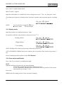
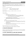
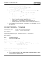
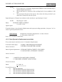
3.5 SELECTION OF THE WORK PROGRAM THROUGH THE
AUX INPUTS
From main menu (dsp1):
1.WORK, 2.PROGRAM MANAGEMENT,
3.GENERAL PARAMETERS, 4.MORE,
choose 1st choice.
Menu PROGRAM NUM.: appears
input the number of program (9) and press "enter".
An “A” before the AUX set program number indicates this operation mode on the working screen.
The AUX input pins are: AUX1, AUX2, AUX3 (J3 25 pole connector).
AUX1
0
0
0
0
1
1
1
1
AUX2
0
0
1
1
0
0
1
1
AUX3
0
1
0
1
0
1
0
1
Set program
Program 1
Program 2
Program 3
Program 4
Program 5
Program 6
Program 7
Program 8
display
A1
A2
A3
A4
A5
A6
A7
A8
A special output error pin (05: 25-pole connector j13) controls the correct selection of the program.
The logic state of the Pin (05) is generally “1”. Should a combination relevant to a non-existing
program be entered, pin 05 will lower and all the cam outputs turn to “0”.
HR5000 User’s Manual Ver.3 09/99
17
HOHNER AUTOMAZIONE SRL
4. GENERAL PARAMETERS
4.1 DYNAMIC DISPLACEMENT
The dynamic displacement is a parameter that allow to drive cams as a function of speed.
With HOHNER HR5000 it's possible to set up 4 different dynamic displacements : every cam may
be associate to one of 4 dynamic displacements .
The displacement-speed function is thought of as linear function (this doesn't bring in valuable
errors).
4.1.1 Dynamic displacement modification
From main menu (dsp1):
1.WORK, 2.PROGRAM MANAGEMENT,
3.GENERAL PARAMETERS, 4.MORE,
choose 3st choice.
Menu of general parameters: 1.DYNAMIC DISPLACEMENT, 2.ENCODER
3.CAM LOCKING, 4.DYNAMIC CONTROL
choose 1st choice.
Menu:
1. MODIFY DYNAMIC DISPLACEMENT
2. CAMS-DISPLACEMENT ASSOCIATION
Choose 1rd choice
Menu:
DYNAMIC DISPLACEMENT
1.A 2.B 3.C 4.D
Choose option:
1. to set up straight line of dynamic displacement A
2. to set up straight line of dynamic displacement B
3. to set up straight line of dynamic displacement C
4. to set up straight line of dynamic displacement D
Menu
displacement parameters appears:
MAX SPEED (A or B or C or D):
DEGREES:
Input max speed of encoder (rpm, 3 digits) and press "enter"
18
HR5000 User’s Manual Ver.3 09/99
HOHNER AUTOMAZIONE SRL
NOTE:
-a-b-c-
If you input zero to dynamic displacement HR5000 return automatically to
dynamic displacement menu
Maz useful speed is a function of the working load: in best condition is 900
rpm
You can input 900 rpm of maz speed, this to have the best precision if you
don't know exactly the real max. speed.
Input the degrees (3 digits) in accordance to the stored max. speed and press "enter"
NOTE:
Menu
Max Degrees: 3600°
DYNAMIC DISPLACEMENT
1.A 2.B 3.C 4.D
appears again
If needed, choose a new dynamic displacement and repeat preceding operations, else press "esc" to
return to general parameters menu.
ATTENTION:
Straight line of dynamic displacement A is the reference
to extra-stroke control (EC)
Press "esc" to return to main menu
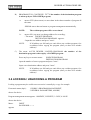
4.1.2 Cams-Dynamic displacement association
Every cam may be associate to one of 4 dynamic displacements .
From main menu (dsp1):
1.WORK, 2.PROGRAM MANAGEMENT,
3.GENERAL PARAMETERS, 4.MORE,
choose 3st choice.
Menu of general parameters: 1.DYNAMIC DISPLACEMENT, 2.ENCODER
3.CAM LOCKING, 4.DYNAMIC CONTROL
choose 1st choice.
Menu:
1. MODIFY DYNAMIC DISPLACEMENT
2. CAMS-DISPLACEMENT ASSOCIATION
Choose 2rd choice
Menu:
N. CAM : 01
0 0 0 0 0 0 0 0
It's possible to press:
- 0:
cam not associated
- 1:
cam associated to dynamic displacement A
- 2:
cam associated to dynamic displacement B
- 3:
cam associated to dynamic displacement C
- 4:
cam associated to dynamic displacement D
HR5000 User’s Manual Ver.3 09/99
19
HOHNER AUTOMAZIONE SRL
To shift to the cam number wanted use arrows key:
ò shift right
ñ shift left
EXEMPLE:
Initial position:
N. CAM : 01
0 0 0 0 0 0 0 0
to associate dynamic dislacement C to cam 01, press 3:
N. CAM : 01
3 0 0 0 0 0 0 0
shift right, press key ò:
N. CAM : 08
3 0 0 0 0 0 0 0
to associate dynamic dislacement D to cam 08, press 4:
N. CAMMA : 08
3 0 0 0 0 0 0 4
shift left, press keyñ:
N. CAMMA : 07
3 0 0 0 0 0 0 4
to associate dynamic dislacement A to cam 07, press 4:
N. CAMMA : 07
3 0 0 0 0 0 1 4.
Press "esc" to return to dynamic displacement menu
Press "esc" to return to general parameters menu
P
ress "esc" to return to main menu
4.2 HOW TO SET UP ENCODER PARAMETERS
HOHNER HR5000 was projected to be connected to any hohner absolute encoder.
To set up the programmer in accordance with used encoder, follow next operations.
NOTE: Encoder parameter could be extracted from code on the cover label of encoder.
From main menu (dsp1):
1.WORK, 2.PROGRAM MANAGEMENT,
3.GENERAL PARAMETERS, 4.MORE,
choose 3st choice.
Menu of general parameters: 1.DYNAMIC DISPLACEMENT, 2.ENCODER
3.CAM LOCKING, 4.DYNAMIC CONTROL
choose 2st choice.
Menu :
1. ENCODER DATA
2. UP/DOWN DIRECTION
Choose option 1 to change encoder data
Menu:
20
ENCODER DATA
NPN_PNP:
HR5000 User’s Manual Ver.3 09/99
HOHNER AUTOMAZIONE SRL
Input code of the used encoder:
Encoder code (output data encoder code) could be of 4 different types:
GRAY
BINARY
GRAY EXCESS
BCD
input "0"
input "1"
input "2"
input "3"
Press "enter".
Choose the output circuits of encoder
NOTE:
NPN
PNP
input "0"
input "1"
If the output circuit of the encoder is LINE DRIVER or PUSH-PULL type, choose
option PNP (input 1)
Press "enter"
HR5000 returns to general parameters menu:
1.DYNAMIC DISPLACEMENT, 2.ENCODER,
3.CAM LOCKING, 4.DYNAMIC CONTROL
Press "esc2 to return to main menu.
Choose option 2 to change increment direction
Menu:
1. UP 2.DOWN
DIRECTION: _
Choose the necessary option.
4.3 CAM LOCKING
From main menu (dsp1):
1.WORK, 2.PROGRAM MANAGEMENT,
3.GENERAL PARAMETERS, 4.MORE,
choose 3st choice.
Menu of general parameters: 1.DYNAMIC DISPLACEMENT, 2.ENCODER
3.CAM LOCKING, 4.DYNAMIC CONTROL
choose 3st choice.
Menu:
INPUT
PASSWORD <---->
Insert the password.If password is right menu of locking/unlocking cams appears.
CAM: 01
0111100001110001
If cam is LOCKED the symbol is "1"
If cam is "UNLOCKED" the symbol is "0", cursor
To shift to the cam number wanted use arrows keys ñò:
HR5000 User’s Manual Ver.3 09/99
21
HOHNER AUTOMAZIONE SRL
EXEMPLE:
Initial position:
CAMMA: 01
0111100001110001
ò Right shifting
CAMMA: 08
0111100001110001
ñ Left shifting
CAMMA: 07
0111100001110001
Press "1" to lock the highlight cam.
Press "0" to unlock the highlight cam.
When all the expected operations will be terminated, press "esc" to return to general parameters
menu: 1.DYNAMIC DISPLACEMENT, 2.ENCODER, 3.LOCKING, 4.DYNAMIC CONTROL.
Press "esc" to return to main menu.
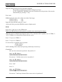
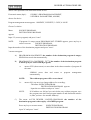
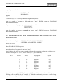
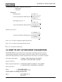
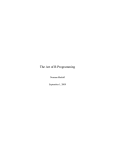
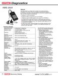
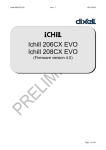
4.4 DYNAMIC CONTROL
4.4.1 Definition of functioning
HR5000 works with 2 controls of encoder dynamic status that visualizes on display 2.
CM (Movement Control): it controls that encoder is really moving, after machine is already
working (and after the initial acceleration).
EC (Extra-stroke Control): when machine stops, EC controls that encoder doesn't go out of
acceptable limits.
N.B. 1)
2)
EC works only in encoder incremental direction
To restore the signals of EC and MC press "esc".
START
STOP
CM
EC
TWAIT
TMAX
TSTOP
DEFINTIONS:
TWAIT:Is the time in wich HR5000 waits before executing CM control.By this, encoder can
accelerate to right speed because HR5000 isn't eneble senses encoder movement.
22
HR5000 User’s Manual Ver.3 09/99
HOHNER AUTOMAZIONE SRL
TMAX: Is the higher gap of time between 2 subsequent position of encoder. It is useful to
know if encoder is still moving. If the real gap exceedes this constant, HR5000 see
the encoder standing still so displays the CM error on dsp2.
TSTOP: Is the higher gap of time between 2 subsequent position of encoder in extra-stroke
space, it is useful to know if encoder really stopped. If the real gap exceedes this
constant, HR5000 see the encoder standing still.
MAXDEG:Maximum rotation thet encoder can do after the machine was stopped: when
exceeded this constant, HR5000 displays EC error on dsp2.
4.4.2 Dynamic set up.
From main menu (dsp1):
1.WORK, 2.PROGRAM MANAGEMENT,
3.GENERAL PARAMETERS, 4.MORE,
choose 3st choice.
Menu of general parameters: 1.DYNAMIC DISPLACEMENT, 2.ENCODER
3.CAM LOCKING, 4.DYNAMIC CONTROL
appears
choose 4st choice.
Menu
Twait:
Tmax:
appears to control CM
Set up Twait time (milliseconds, min 10, max 2550) to start CM after a gap of time machine start.
Press "enter"
Set up Tmax time (milliseconds, min 10, max 2550) to control movement of encoder.
If the real gap exceeds this constant, HR5000 see the encoder standing still so displays on
dsp2 the CM error and changes signal status on CM pin of I/O AUX connector.
Press "enter"
Menu
Tstop:
MaxDeg:
appears to control EC.
Set up Tstop time (milliseconds, min 10, max 2550) to verify if encoder stops.
Press "enter"
Input max. degrees for extra-stroke and press "enter".
HR5000 User’s Manual Ver.3 09/99
23
HOHNER AUTOMAZIONE SRL
NOTE: When exceeded this constant, HR5000 displays EC error on dsp2 and change signal
status on EC pin of I/O AUX connector.
4.4.3 Braking deviation
Braking deviation is the space between the machine switching off point (START signal low) and
point that for HR5000 encoder is stopped (Itjudges by Tstop constant).
This parameter (SCFR) is visualized on display 2 (dsp2) when HR5000 is an working mode.
To the value of SCFR is added the dynamic displacement A.
24
HR5000 User’s Manual Ver.3 09/99
HOHNER AUTOMAZIONE SRL
5. OTHER FUNCTION
5.1 WORK SIMULATOR
This cam programmer has a built in function to operate without any encoder.
From main menu (dsp1):
1.WORK, 2.PROGRAM MANAGEMENT,
3.GENERAL PARAMETERS, 4.MORE,
choose 1st choice.
Menu N. PROGRAM: appears
Input the program number to be used (1÷8) and press "enter".
NOTE:
if program is empty display visualizes PROGRAM NOT STORED, press any key to
return to menu N. PROGRAM:
The working data menu appears: PR. DSB. POS. SPD. (PR = program, DSB = base displacement,
POS= position, SPD = speed); it is related to the chosen program.
Press "esc" 2 times to return to main menu.
Choose 4 th choice.
Menu of more choices appears:
1.SIMULATION 2.DATE/TIME
3.RS232C 4.COUNTRY
Choose 1 th choice.
Every time you press "enter" you will shift from simulation "on" to "off" and vice versa.
Press "esc" to return to previous menu.
5.2 DATE/TIME
From main menu (dsp1):
1.WORK, 2.PROGRAM MANAGEMENT,
3.GENERAL PARAMETERS, 4.MORE,
choose 4st choice.
Menu of more choices appears:
1.SIMULATION 2.DATE/TIME
3.RS232C 4.COUNTRY
Choose 2 th choice.
HR5000 User’s Manual Ver.3 09/99
25
HOHNER AUTOMAZIONE SRL
Menu
DATE: XX/XX d/m
TIME: YY/YY h/m
appears
Insert: day (d) - month (m) - hour (h) - minutes (m), press "enter" after every insertion.
5.3 SERIAL CONNECTIONS TO PC
5.3.1 SET UP OF HR5000 TO WORK IN SERIAL CONNECTION TO PC
From main menu (dsp1):
1.WORK, 2.PROGRAM MANAGEMENT,
3.GENERAL PARAMETERS, 4.MORE
Choose 4th choice.
Menu of more choices appears:
1.SIMULATION 2.DATE/TIME
3.RS232C 4.COUNTRY
Choose 3th choice.Hr5000 displays message "WAITING CONNECTION" on display 1.
Start interfacing program on PC. HR5000 displays message "CONNECTED" on display 1.
NOTE: Press "Esc" on HR5000 to stop the communication in any moment.
At the and of working close PC program. HR5000 display message "WAITING CONNECTION"
on display1.
Press "esc" on HR5000 to return to More choices menu.
Press "esc" to return to main menu.
5.3.2 CAMS AND PROGRAMS DESCRIPTION INSERT
Connect HR5000 to PC as show in 5.3.1 section
Insert description by following operations in PC program.
Every time you choose a program HR5000 will visualize its description on display 2.
5.4 LANGUAGE
From main menu (dsp1):
1.WORK, 2.PROGRAM MANAGEMENT,
3.GENERAL PARAMETERS, 4.MORE
Choose 4th choice.
Menu of more choices appears:
1.SIMULATION 2.DATE/TIME
3.RS232C 4.COUNTRY
Choose 4th choice.
26
HR5000 User’s Manual Ver.3 09/99
HOHNER AUTOMAZIONE SRL
Menu
1.I
4.F
2.GB
5.E
3.D
1.
2.
3.
4.
5.
ITALIAN
ENGLISH
GERMAN
FRENCH
SPANISH
appears
Choose
press "enter"
Press "esc" on HR5000 to return to More choices menu.
Press "esc" to return to main menu.
HR5000 User’s Manual Ver.3 09/99
27
HOHNER AUTOMAZIONE SRL
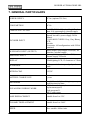
6. MESSAGE MANAGEMENT
6.1 INTRODUCTION:
HR5000 allow to insert 127 messages by using a serial input connected to PC
To connect HR5000 to PC see 5.3 section (SERIAL CONNECTION TO PC).
Messages send are stored in RAM memory (using floating battery) and can be visualized by a
request arriving from Input Messages connector.
All recalled messages stay in display memory area till they are deleted by using keyboard.
When a stored message is recalled, HR5000 visualizes it on dsp2 and give to it the receiving
ordering number (temporal ordering).
Every time there is a displaying request all functions shown on dsp2 are disabled.
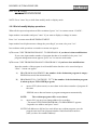
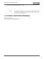
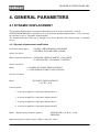
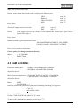
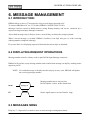
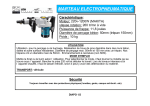
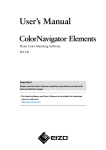
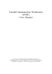
6.2 DISPLAYING REQUEST OPERATIONS
Message number must be a binary code on pins D0-D6 Input Message connector:
HR5000 will read the set up message number and visualize that message on dsp2 by sending strobe
signal on pin D7.
NOTE: If a recalled message is already stored in display memory area, HR5000 will update
the receiving message number.
Message number has to stay on pins
D0-D6 20µSec. before strobe attack front
D0-D6
D7
message N.
Strobe
Strobe signal must be at least 50mSec. large.
6.3 MESSAGES MENU
Keep key "*" depressed 2 seconds or more to enter messages management menu:
28
HR5000 User’s Manual Ver.3 09/99
HOHNER AUTOMAZIONE SRL
ñP òS 0.DEL MESSAGE
RECEIVING MESSAGE N.
Press ñ arrow key to scroll to Previous message.
Press ò arrow key to s
croll to Next message.
Press "0" key to delete from display memory area message actually displayed.
On display 2 HR5000 visualizes messages of number on display 1.
HR5000 User’s Manual Ver.3 09/99
29
HOHNER AUTOMAZIONE SRL
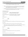
7. GENERAL PARTICULARS
POWER SUPPLY
24 Vac (options 220 Vac)
CONSUMPTION
10 VA
CAMS STATIC OUTPUT
ENCODER INPUT
AUXILIARY INPUT/ (OUTPUT)
MESSAGES INPUT
N° 16/32, 24Vdc-400mA, ( Single Total
cams: 4A) optocoupled; external supply.
Optocoupled input for 360 positions/rev.
Internal encoder‘s power supply 24Vdc
300mA.
AVAILABLE CODES: Gray, Gray Binary,
BCD.
Encoder
Electronics: All configurations with 24Vdc
permitted
Input/(output) optocoupled 24Vac(dc) for
functions; external supply.
Optocoupled input to interface PLC;
external supply 24Vac/dc
DISPLAY
2 Backlighting LCD, 12 characters x 2 lines
KEYBOARD
16 Keys, anti-abrasive panel, polycarbonate
made
INTERFACING
RS232C
BATTERY CHARGE LIFE
6 years
PROGRAMS
VISUALIZING DURING WORK
8 available + 1 (0) for editing/temporary
modifications/real time
DSP1: directed degrees, base
displacement,speed,
Work program N.
DSP2: cams status
BASE DISPLACEMENT
Settable from 0 to 359°
DYNAMIC DISPLACEMENT
Settable from 0 to 3600°
SPEED
Max. settable: 900rev/min.
30
HR5000 User’s Manual Ver.3 09/99
HOHNER AUTOMAZIONE SRL
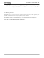
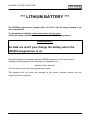
*** LITHIUM BATTERY ***
The HR5000 programmer is supplied with a 3.6 Volt - Size AA battery housed in its
rear compartment.
To get maximum reliability, replace the battery every 6 years.
Check the battery installation date on the lid of the HR5000 programmer.
WARNING:
No data are lost if you change the battery when the
HR5000 programmer is on.
Should the battery be replaced when the HR5000 programmer is off, the following
message will be displayed when switching the programmer on:
“Attention: Ram data lost”
You will need to enter the working parameters again.
This operation will not cause any damage to the system software anyway and the
equipment will run regularly.
HR5000 User’s Manual Ver.3 09/99
31
HOHNER AUTOMAZIONE SRL
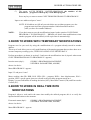
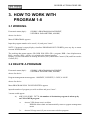
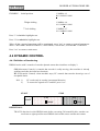
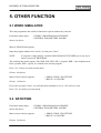
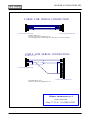
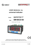
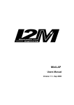
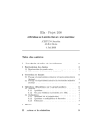
CABLE FOR SERIAL CONNECTION
J7
J8
1
2
3
4
5
6
7
8
9
1
2
3
4
5
6
7
8
9
9 POLE TANK CONNECTOR
9 POLE TANK CONNECTOR
LENGHT MAX 15 m.
Connect only when equipment is off
Use a shielded cable, connecting the screen to pin 5 on one side only
CABLE FOR SERIAL CONNECTION
SERIALE
J7
J8
1
2
3
4
5
6
7
8
9
1
2
3
4
5
6
7
8
9
10
11
12
13
14
15
16
17
18
19
20
21
22
23
24
25
9 POLE TANK CONNECTOR
LENGHT MAX 15 m.
Connect only when equipment is off
25 POLE TANK CONNECTOR
Hohner Automazione s.r.l.
Serial connection
Data: 17-12-96 File HR5CONN2
32
HR5000 User’s Manual Ver.3 09/99
HOHNER AUTOMAZIONE SRL
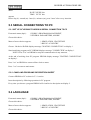
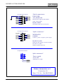
J4 15pole tank connector
1
9
D6_EN
C
D7_EN
C
D8_EN
C
D9_EN
C
2
+24V_Encod
er
10
D0_EN
C
D1_EN
C
D2_EN
C
D3_EN
C
D4_EN
C
D5_EN
C
3
11
4
12
5
13
6
14
15
8
+24V_Encoder/GND
Internal power supply for ENCODER
24Vdc 300mA MAX
15pole connector f.
1
9
2
10
D1_MS
G
D3_MS
G
D5_MS
G
D7_MS
G
ENCODER
D0_ENC...D9ENC
ENCODER inputs (6mA for channel)
7
J5 15pole tank connector
COMMS
15pole connector m.
3
11
4
12
5
13
6
14
D0_MS
G
D2_MS
G
D4_MS
D6_MS
G
MESSAGES
COMMSG
Common , positiv or negative, power supply
7
15
D0_MSG...D7_MSG
Inputs from PLC (24Vdc / 6mA for channel)
8
D0_MSG...D7_MSG:
Display messages inputs bits
J6 9pole tank connector
9pole connector f.
U?
1
6
2
7
Power supply
3
8
4
24 Vac 0.5A
HR5000 power supply
9
5
DB9
A
24VAC
24VAC
1
Hohner Automazione s.r.l.
Connections I/O
Data: 17-12-96 File HR5CONN1
HR5000 User’s Manual Ver.3 09/99
33
HOHNER AUTOMAZIONE SRL
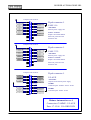
J1 25pole tank connector
+24V
25pole connector f.
1
14
CAM 1
CAM 3
CAM 5
CAM 7
CAM 9
CAM 11
CAM 13
CAM 15
2
15
CAM 2
3
16
CAM 4
4
17
CAM 6
5
18
CAM 8
6
19
7
20
8
21
9
22
10
CAM 10
CAM 12
CAM 14
CAM 1-16
+24V/GND:
External power supply cam
CAM 1...CAM 16
Outputs cam 24Vdc 400mA
CAM 16
Electronic protection with
23
11
24
automatic reset
12
25
13
J2 25pole tank connector
+24V
25pole connector f.
1
14
CAM 17
CAM 19
CAM 21
CAM 23
CAM 25
2
15
CAM 20
CAM 17-32
17
CAM 22
+24V/GND:
18
CAM 24
4
5
6
19
CAM 27
7
CAM 29
8
CAM 31
9
CAM 18
16
3
20
21
22
10
CAM 26
CAM 28
CAM 30
External power supply cam
CAM 17...CAM 32
Outputs cam 24Vdc 400mA
CAM 32
Electronic protection with
23
11
24
automatic reset
12
25
13
J3 25pole tank connector
COM01
START
AUX1
AUX2
+24V
AUX3
25pole connector f.
1
14
COM02
15
AUX4
16
AUX5
2
3
4
17
5
18
6
AUX6
AUX7
19
7
20
8
21
C.M
.
READY
O5
O7
9
22
10
23
11
24
12
25
13
E.C.
PRES.MESS.
I/O AUX
+24V/GND:
Outputs AUX external power supply
COM01
Common inputs: START - AUX1..AUX3
COM02
Common inputs: AUX4...AUX7
O6
O8
Hohner Automazione s.r.l.
Connessioni CAMME - I/O AUX
Data: 17-12-96 File HR5CONN
34
HR5000 User’s Manual Ver.3 09/99
HOHNER AUTOMAZIONE SRL
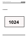
PASSWORD
1024
HR5000 User’s Manual Ver.3 09/99
35
HOHNER AUTOMAZIONE SRL
36
HR5000 User’s Manual Ver.3 09/99
HOHNER AUTOMAZIONE SRL
HOHNER AUTOMAZIONE SRL
PIAZZALE COCCHI, 10 21040 VEDANO OLONA (VA) TEL. +039 0332 866109 - FAX +03
9 0332 866066
http//www.hohner.it e-mail:[email protected]
HR5000 User’s Manual Ver.3 09/99
37