1
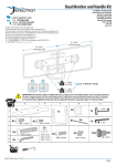
EWM12U242418-R2 EWM20U362430-R2 EWM12UMFD-R2 EWM26URK-R2
EWM12U242424-R2 EWM20U362430-R2 EWM20UMFD-R2EWM45DAB-R2
EWM12U242430-R2 EWM26U482418-R2 EWM26UMFD-R2EWM90DAB-R2
EWM20U362418-R2 EWM26U482424-R2EWM12URK-R2 EWM1U6SB-R2
EWM20U362424-R2 EWM26U482430-R2EWM20URK-R2
Elite™ Wallmount Cabinet User’s Manual
Fully assembled, ready-to-use wallmount cabinets.
BLACK BOX
®
EC24U3032
Customer
Support
Information
Order toll-free in the U.S.: Call 877-877-BBOX (outside U.S. call 724-746-5500)
FREE technical support 24 hours a day, 7 days a week: Call 724-746-5500 or fax 724-746-0746
Mailing address: Black Box Corporation, 1000 Park Drive, Lawrence, PA 15055-1018
Web site: www.blackbox.com • E-mail: [email protected]
Trademarks Used in this Manual
Trademarks Used in this Manual
Black Box and the Double Diamond logo are registered trademarks, and Elite is a trademark, of BB Technologies, Inc.
PLEXIGLAS is a registered trademark of Roehm GmbH & CO.
VELCRO is a registered trademark of Velcro Industries B.V.
Any other trademarks mentioned in this manual are acknowledged to be the property of the trademark owners.
We‘re here to help! If you have any questions about your application
or our products, contact Black Box Tech Support at 724-746-5500
or go to blackbox.com and click on “Talk to Black Box.”
You’ll be live with one of our technical experts in less than 60 seconds.
Page 2
724-746-5500 | blackbox.com
EC24U3032
Table of Contents
Preface.................................................................................................................................................................................................... 4
Safety
.................................................................................................................................................................................... 4
Safety Symbols Used in this Manual........................................................................................................................................... 4
Safety Considerations................................................................................................................................................................ 4
1. Specifications .................................................................................................................................................................................... 5
1.1Size .................................................................................................................................................................................... 5
1.2General
.................................................................................................................................................................................... 5
2. Overview
.................................................................................................................................................................................... 8
2.1 Introduction.............................................................................................................................................................................. 8
2.2 Features.................................................................................................................................................................................... 8
2.3 What’s Included........................................................................................................................................................................ 8
2.4 Optional Accessories................................................................................................................................................................. 8
3. Mounting Instructions........................................................................................................................................................................ 9
3.1 Receiving, Unpacking, and Removing the Elite Wallmount Enclosure from the Pallet................................................................. 9
3.2 Wood Studded Wall.................................................................................................................................................................. 9
3.3 Loading Equipment..................................................................................................................................................................10
3.4Power...................................................................................................................................................................................10
3.5 Protective Grounding...............................................................................................................................................................10
3.5.1 Connecting the Main Protective Grouding Stud to the Dedicated Branch Ground.......................................................10
3.5.2 Connecting the Main Protective Grounding Stud to the Protective Bonding Conductors..............................................10
4. Operation
...................................................................................................................................................................................11
4.1 Operating the Door..................................................................................................................................................................11
4.2 Removing or Installing a Door..................................................................................................................................................11
4.3 Reversing a Door......................................................................................................................................................................11
4.4 Adjusting the Rails...................................................................................................................................................................12
5.
Optional Accessories Drawings..........................................................................................................................................................13
EC24U3032
Page 3
Preface/Safety Information
Preface
This manual is provided to prevent service personnel from committing an act that results in the risk of fire, electric shock, or injury
to persons. Only trained service personnel should receive, unpack, and assemble the Elite Wallmount Cabinet. In addition, only
trained service personnel should install equipment in enclosures.
Safety
Safety Symbols Used in this Manual
This manual provides general safety guidelines to be observed during installation, operation, and maintenance of the Elite
Wallmount Cabinet.
WARNING: Failure to follow directions in the warning could result in injury to persons or loss of life.
CAUTION: Failure to follow directions in the caution could result in damage to equipment or storage data.
Safety Considerations
WARNING: Improper handling and use of the Elite Wallmount Cabinet could result in equipment damage, serious injury,
or possible death.
Only trained service personnel should be used to remove the enclosure from the pallet. Also be sure you have a sufficient number
of service personnel. Do not attempt to move enclosures by yourself.
Only UL® Listed ITE units should be installed inside the Elite Wallmount Cabinet.
Be sure to read and follow all individual manufacturer equipment manuals for safety and installation instructions.
The Elite Wallmount Cabinet was not evaluated as a fire enclosure.
Proper spacing is required when installing electrical equipment to avoid electrical shock.
The ambient temperature operating range for the Elite Walllmount Cabinet and accessories is +50 to +95° F (+10 to +35° C).
The non-operating temperature is -4 to +140° F (-20 to +60° C).
Page 4
724-746-5500 | blackbox.com
EC24U3032
Chapter 1: Specifications
1. Specifications
1.1 Size
Table 1-1 lists specifications for the cabinet shown in Figures 1-1 through 1-4.
Table 1-1. Cabinet size specifications.
Door
Height
Exterior
Depth
Exterior
Depth
w/Hinges
Exterior
Height
Interior
Depth*
Interior
Height**
Interior
Width***
Part Number
# of RUs
Height
Width
Depth
Door
Width
EWM12U242418-R2
12
24"
24"
18"
21.125"
17.875"
18"
18.75"
24"
17.25"
23.8"
23.8"
EWM12U242424-R2
12
24"
24"
24"
21.125"
17.875"
24"
24.75"
24"
23.25"
23.8"
23.8"
EWM12U242430-R2
12
24"
24"
30"
21.125"
17.875"
30"
30.75"
24"
29.25"
23.8"
23.8"
EWM20U362418-R2
20
38.5"
24"
18"
21.125"
29.875"
18"
18.75"
38.5"
17.25"
35.8"
23.8"
EWM20U362424-R2
20
38.5"
24"
24"
21.125"
29.875"
24"
24.75"
38.5"
23.25"
35.8"
23.8"
EWM20U362430-R2
20
38.5"
24"
30"
21.125"
29.875"
30"
30.75"
38.5"
29.25"
35.8"
23.8"
EWM26U482418-R2
26
49"
24"
18"
21.125"
41.875"
18"
18.75"
49"
17.25"
47.8"
23.8"
EWM26U482424-R2
26
49"
24"
24"
21.125"
41.875"
24"
24.75"
49"
23.25"
47.8"
23.8"
EWM26U482430-R2
26
49"
24"
30"
21.125"
41.875"
30"
30.75"
49"
29.25"
47.8"
23.8"
*Back wall to front door
**Base to top
***Side wall to side wall
1.2 General
Construction:
Body: 14-gauge steel;
Doors: 16-gauge steel;
Rails: 12-gauge steel
Finish: Black powder coat
Grounding: Ground studs located on rear section, middle section, and door
PLEXIGLAS® Thickness: 0.2"(0.5 cm)
Distance to Rear Section at Maximum Rail Depth: 1.18"(0.48 cm)
Distance to Front Door at Maximum Rail Depth: 0.75" (1.91 cm)
Rail Type: 10-32 tapped
Minimum/Maximum Rail Depth:
18" Deep Cabinet: 0 to 7.56" (0 to 19.2 cm);
24" Deep Cabinet: 0 to 13.56" (0 to 34.4 cm);
30" Deep Cabinet: 0 to 19.56" (0 to 49.7 cm)
Weight Capacity:
24"H: 150 lb. (68 kg);
36"H: 250 lb. (114 kg);
48"H: 300 lb. (136 kg)
EC24U3032
724-746-5500 | blackbox.com
Page 5
Chapter 1: Specifications
One pair of adjustable
mounting rails tapped
#10-32 UNF-2B
Height
17.749" opening
18.312" centers
Mounting rails
Width
Figure 1-1. Front view (doors removed for clarity).
Depth — see Table 1-1
7.25
Depth
Figure 1-2. Right side view.
Page 6
724-746-5500 | blackbox.com
EC24U3032
Chapter 1: Specifications
10.00
3RU = 4.75
18.31
Figure 1-3. Top view.
9.00
Height
(see Table 1-1)
9.00
10.00
16.00
Figure 1-4. Back view.
EC24U3032
Page 7
Chapter 2: Overview
2. Overview
2.1 Introduction
Elite Wallmount Cabinets are designed to securely hold 19" rackmount equipment, networking equipment, phone
equipment, etc. in tight spaces or closets.
2.2 Features
• Large openings in the back panel enable easy installation of pre-wired equipment such as patch panels.
• Ships with one conduit panel on the top and one solid panel on the bottom.
• 3 RU Elite Cabinet accessories also fit the Elite Wallmount 3 RU openings, top and bottom.
• Welded steel frame.
• Includes one pair of 10-32 tapped rails.
• Additional rails are available for four-point mounting.
• Doors can be reversed to open left or right.
• Doors available in mesh and PLEXIGLAS.
• Double hinged for easy access to rear of equipment.
• Locking rear section.
• Accessories brackets provide additional moutning options in the rear section.
2.3 What’s Included
Your package should include the following items. If anything is missing or damaged, please contact Black Box Technical Support
at 724-746-5500 or [email protected].
• Fully assembled Elite Wallmount Cabinet
• (11) ground studs
• (30) 10-32 mounting screws
• (2) pairs of keys
• Mounting hardware for wood studded wall only
- The 24" and 36"H cabinets include (4) 1⁄4-10 x 2" lag bolts, (4) flat washers, and (4) locking washers.
- The 48" cabinets include (6) 1⁄4-10 x 2" lag bolts, (6) flat washers, and (6) locking washers.
• (1) pair of 10-32 mounting rails
• This user manual
2.4 Optional Accessories
• 3 RU Conduit Adapter Plate (ECP3U)
• Extra pair of rails for 24"H wallmount (EWM12URK-R2)
• 3 RU Brush Grommet Kit (ECBGK3U) • Extra pair of rails for 36"H wallmount (EWM20URK-R2)
• 45-Degree Angle Bracket (EWM45DAB-R2)
• Extra pair of rails for 48"H wallmount (EWM26URK-R2)
• 90-Degree Angle Bracket (EWM90DAB-R2)
• 1 RU x 6"D standoff bracket for rear section (EWM1U6SB-R2)
• 3 RU Waterfall Radius Bracket (ECW3U)
• Fan (RMT373-R3)
• 3 RU Gland Plate Kit (EC3UGP)
• Fan (RMT373AE-R3)
• 3 RU Filler Panel (RMTB03)
• Vent Cover Plate (EWMDCP-R2
Page 8
724-746-5500 | blackbox.com
EC24U3032
Chapter 3: Mounting Instructions
3. Mounting Instructions
3.1 Receiving, Unpacking, and Removing the Elite Wallmount Enclosure from the Pallet
Inspect for damage and report damage if there is damage before receiving. Refer to Section 2.3 for what‘s included
in the package.
Unpack the enclosure by carefully removing the corrugated carton and corners. Avoid damaging the enclosure when removing
packaging.
WARNING: O
nly trained service personnel should be used to remove the enclosure from the pallet. Also be sure you have a
sufficient number of service personnel. Do not attempt to move enclosures by yourself.
WARNING: B
e careful when moving enclosures before installation. Sudden stops and starts, excessive force, obstructed routes,
and uneven floor surfaces may cause the enclosure to topple over.
3.2 Wood Studded Wall
Once the location on the wall has been determined, inspect the wall surface. The wall must be flat and square in the horizontal
and vertical plane to ensure the Elite Wallmount Cabinet closes correctly. If the wall is not flat and square, you might need to use
shims.
You can remove the rear section of the cabinet by removing the hinges. Mount the rear section to the wall using the
included hardware or install two horizontal bolts in studs (DO NOT TIGHTEN!) using a level. Hang the rear section on the two
bolts, install the lower two bolts (line up with a level) and tighten. Then tighten the upper two bolts.
WARNING: Improper handling and use of the Elite Wallmount Enclosure could result in equipment damage, serious injury,
or possible death.
Masonry Wall Surface
For a masonry wall surface, the installer must provide the appropriate hardware.
EC24U3032
Page 9
Chapter 3: Mounting Instructions
3.3 Loading Equipment
WARNING: Only install equipment after the Elite Wallmount has been properly secured and mounted to the wall.
Maximum Load Capacity
Rated or maximum load capacity for the Elite Wallmount: 24"H = 150 pounds
36"H = 250 pounds
48"H = 300 pounds
3.4 Power
When using power distribution units (PDUs), each PDU should be connected to a committed branch circuit that is rated for the
continuous load of all the equipment connected.
When not using a PDU, each piece of equipment should be connected to a dedicated branch circuit.
3.5 Protective Grounding
A main protective earthing stud and grounding studs are provided.
WARNING: T o avoid injury to persons or loss of life, ground each enclosure individually to the dedicated branch circuit earthing
ground.
3.5.1 Connecting Main Protective Grouding Stud to the Dedicated Branch Circuit Earthing Ground
Conductor
Connect the dedicated branch circuit ground conductor to the main protective earthing stud located inside at the bottom rear of
the enclosure chassis using a listed ring or closed-loop terminal.
3.5.2 Connecting Main Protective Grounding Stud to the Protective Bonding Conductors
Connect the rear door to the main protective grounding stud located inside at the bottom rear of the enclosure chassis
using a listed ring or closed-loop terminal. Connect the front door to the grounding stud located inside at the bottom front
of the enclosure chassis using a listed ring or closed-loop terminal.
Page 10
724-746-5500 | blackbox.com
EC24U3032
Chapter 4: Operation
4. Operation
4.1 Operating the Door
The Elite Enclosure is supplied with two locks (one for the front door and one to lock the middle section to the rear section).
The middle section and rear section incorporate a grabber catch that enables the middle section to be held shut without locking.
4.2 Removing or Installing a Door
Open the door beyond 90°, remove the top half of the upper hinge, then grasp the door with both hands and carefully lift it
upward. When the door is free of two hinge pins, pull the door away from the enclosure. To attach the door, align both door
hinges to their respective hinge pins on the enclosure and slowly slide the door down until seated.
4.3 Reversing a Door
The front and rear doors are installed with two hinges as standard from Black Box. Removing the hinges enables you to reverse
the door by flipping them over and reinstalling the hinges using the universal mounting holes. All the enclosure frames and doors
can be hinged right- or left-hand. The handle can be reversed along with the hinging. See Figure 4-1.
Reversible
hinge
(female)
Pivot
washer
Reversible
hinge (male)
Flat head
Phillips screw
#10-32 x 3⁄8"
Flat head
Phillips screw
#10-32 x 3⁄8"
Figure 4-1. Reversing a door.
EC24U3032
Page 11
Chapter 4: Operation
4.4 Adjusting the Rails
Mounting Rails
One pair of 10-32 vertical mounting rails is installed in all Elite Wallmount Cabinets. Additional mounting rails are available as
accessories.
Figure 4-2. Adjusting the vertical mounting rails.
Rails are attached using a sliding nut and hex bolt. Loosen both top and bottom bolts, using an 11-mm socket set, then adjust the
rails front to back.
Page 12
724-746-5500 | blackbox.com
EC24U3032
Chapter 5: Optional Accessories Drawings
5. Optional Accessories Drawings
Figures 5-1 through 5-5 illustrate some of the Elite Wallmount Cabinet’s optional accessories.
Optional angle brackets attach to the back panel of the cabinet for mounting 19" rackmount equipment such as patch panels
and PDUs.
Vertical stationary
rails in rear section
tapped #10-32
Optional
EWM90DAB-R2—90°
angle bracket
18.31
centers
Optional
EWM45DAB-R2—45°
angle bracket kit
Figure 5-1. Angle bracket and angle bracket kit.
Use the brush grommet kit to protect the interior of the cabinet from dust and debris.
Optional ECBGK3U brush
grommet kit for 3U opening
Figure 5-2. Optional ECBGK3U brush grommet kit for 3U opening.
EC24U3032
Page 13
Chapter 5: Optional Accessories Drawings
Use the gland plate kit to close around cables to prevent unwanted airflow and keep dust and debris out.
Optional EC3UGP
Gland Plate Kit
Figure 5-3. Optional EC3UGP Gland Plate Kit.
Use the waterfall bracket to maintain bend radius when routing cables into the cabinet.
Optional ECW3U
waterfall bracket
Figure 5-4. Optional ECW3U Waterfall Bracket.
Page 14
724-746-5500 | blackbox.com
EC24U3032
Chapter 5: Optional Accessories Drawings
Use the vent cover plate to keep dust and debris from entering the cabinet.
EWMDCP-R2
Vent Cover Plate
Figure 5-5. EWMDCP-R2 Vent Cover Plate.
EC24U3032
Page 15
Black Box Tech Support: FREE! Live. 24/7.
Tech support the
way it should be.
Great tech support is just 60 seconds away at 724-746-5500 or blackbox.com.
About Black Box
Black Box Network Services is your source for an extensive range of networking and infrastructure products. You’ll find everything
from cabinets and racks and power and surge protection products to media converters and Ethernet switches all supported by
free, live 24/7 Tech support available in 60 seconds or less.
© Copyright 2014. All rights reserved.
EWM12U242418-R2, rev. 4
724-746-5500 | blackbox.com