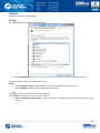
Download TRBOnet Dispatch Software Administration Guide

Transcript
TRBOnet Dispatch
Software
Administration Guide
July 17, 2014
1
Table of Contents
Preface .................................................................................................................................................................... 8
About the Company ............................................................................................................................................ 8
Contact Details .................................................................................................................................................... 8
Copyright ............................................................................................................................................................. 8
Hardware and Software Requirements ................................................................................................................... 9
System Architecture Overview .............................................................................................................................. 10
TRBOnet RadioServer and Consoles .................................................................................................................. 10
MOTOTRBO Radio Systems ............................................................................................................................... 11
Conventional ................................................................................................................................................. 11
IP Site Connect .............................................................................................................................................. 11
Capacity Plus ................................................................................................................................................. 12
Linked Capacity Plus ...................................................................................................................................... 13
Connect Plus .................................................................................................................................................. 14
IP Backend Network Requirements ............................................................................................................... 15
Linked Capacity Plus Specific Requirements .............................................................................................. 15
TRBOnet RadioServer Installation ......................................................................................................................... 16
Installation Steps ............................................................................................................................................... 16
TRBOnet RadioServer Configuration ..................................................................................................................... 17
License Information........................................................................................................................................... 17
License Types................................................................................................................................................. 17
Move TRBOnet Dispatch Software to Another Server PC .............................................................................. 19
Use Spare Repeater ....................................................................................................................................... 19
Dispatch Connections Limitations ................................................................................................................. 19
License Manager ........................................................................................................................................... 20
Install TRBOnet RadioServer Service ................................................................................................................. 24
Create TRBOnet RadioServer Database ............................................................................................................. 25
Database Authentication ............................................................................................................................... 26
Configure Network Parameters ......................................................................................................................... 28
Service Management......................................................................................................................................... 30
Automatic "Check Radio" Service .................................................................................................................. 31
Location Service ............................................................................................................................................ 31
System Planner Window ............................................................................................................................... 32
Advanced GPS Parameters ............................................................................................................................ 33
Telemetry Service .......................................................................................................................................... 35
2
Text Messaging Service ................................................................................................................................. 35
Indoor Service ............................................................................................................................................... 35
Advanced Settings ............................................................................................................................................. 36
Map Servers for Geocoding ........................................................................................................................... 37
Local Agent ........................................................................................................................................................ 39
MOTOTRBO System Elements ....................................................................................................................... 41
Add a Control Station .................................................................................................................................... 42
Control Station Connection Modes ........................................................................................................... 44
Single Station ......................................................................................................................................... 44
Capacity Plus TRBOnet........................................................................................................................... 45
Capacity Plus MOTOTRBO ..................................................................................................................... 46
IP Site Connect....................................................................................................................................... 47
Common Channel .................................................................................................................................. 48
Add a MOTORBO Repeater ........................................................................................................................... 49
MNIS Data Service ..................................................................................................................................... 51
DDMS Service ............................................................................................................................................ 52
Repeater's Advanced Settings ................................................................................................................... 53
Privacy ................................................................................................................................................... 54
Slots ........................................................................................................................................................... 55
Local Slots .................................................................................................................................................. 56
Audio Path ................................................................................................................................................. 57
Add TRBOnet.Swift Agent.............................................................................................................................. 58
TRBOnet.Swift Agent's Advanced Settings ................................................................................................ 60
Reserve Agent ........................................................................................................................................... 61
Add XRC-9000 Controller ............................................................................................................................... 62
Advanced Settings ..................................................................................................................................... 64
Add XRT-9000 Controller ............................................................................................................................... 65
Audio Paths ............................................................................................................................................... 67
Add a Selex Repeater .................................................................................................................................... 68
Selex Repeater Advanced Settings ............................................................................................................ 70
Selex Repeater Slots .................................................................................................................................. 71
Analog Mode ............................................................................................................................................. 72
Services ......................................................................................................................................................... 73
Analog Control Stations ..................................................................................................................................... 75
Add an Analog Control Station ...................................................................................................................... 76
Serial Port .................................................................................................................................................. 78
3
Remote Agents .................................................................................................................................................. 79
Friendly Servers ................................................................................................................................................. 81
External PBX Server ........................................................................................................................................... 83
Advanced Settings ......................................................................................................................................... 84
Data Sources ..................................................................................................................................................... 85
COM Ports ..................................................................................................................................................... 86
TCP/IP ............................................................................................................................................................ 88
Email Settings .................................................................................................................................................... 90
POP3 Server................................................................................................................................................... 91
SMTP Server .................................................................................................................................................. 92
SMS Settings ...................................................................................................................................................... 93
Administrator Activity in the Dispatch Console ..................................................................................................... 95
Dispatch Console Menu..................................................................................................................................... 95
File ................................................................................................................................................................. 96
View .............................................................................................................................................................. 98
Map ............................................................................................................................................................. 109
Map Types ............................................................................................................................................... 112
Tools ............................................................................................................................................................ 117
Options .................................................................................................................................................... 122
Sound .................................................................................................................................................. 122
Map ..................................................................................................................................................... 123
Coverage Map ..................................................................................................................................... 124
Hardware ............................................................................................................................................. 126
Advanced ............................................................................................................................................. 128
Volume ................................................................................................................................................ 131
Alarm ................................................................................................................................................... 132
Set Language ........................................................................................................................................... 133
Change Password .................................................................................................................................... 133
Help ......................................................................................................................................................... 133
Route Management ........................................................................................................................................ 134
Radio Allocation .............................................................................................................................................. 145
Beacons ........................................................................................................................................................... 147
Administration................................................................................................................................................. 150
RadioServer ................................................................................................................................................. 150
Database.................................................................................................................................................. 151
Radio Systems ......................................................................................................................................... 152
4
Radio Systems Properties .................................................................................................................... 153
System Bridging ....................................................................................................................................... 159
System Bridging Types ......................................................................................................................... 162
Phone Calls .............................................................................................................................................. 166
Outgoing Calls Configuration ............................................................................................................... 167
Incoming Calls Configuration ............................................................................................................... 168
Tasks ........................................................................................................................................................ 170
Agenda ................................................................................................................................................ 170
Audio Recorder for NetCRR ................................................................................................................. 172
Import Beacon Data from DB «Firebird» ............................................................................................. 174
Export Data .......................................................................................................................................... 176
Geofencing .......................................................................................................................................... 181
Idle Time .............................................................................................................................................. 186
Lone Worker ........................................................................................................................................ 188
Radio Allocation (Sprite Forms) ........................................................................................................... 198
Scheduled Task .................................................................................................................................... 200
SMS and Email Notifications ................................................................................................................ 204
User Activity ........................................................................................................................................ 208
Voice Message ..................................................................................................................................... 211
Event/Alarm Management ...................................................................................................................... 217
Telemetry ................................................................................................................................................ 224
Radio Groups Telemetry ...................................................................................................................... 225
Telemetry #N ....................................................................................................................................... 230
Tools ........................................................................................................................................................ 231
Swift.Tracker Configuration Tool ......................................................................................................... 231
Templates for Extended Messages ...................................................................................................... 239
Indoor 2D Map Converter ....................................................................................................................... 244
Disabled Radios ....................................................................................................................................... 246
Dispatchers .............................................................................................................................................. 248
Email Groups ........................................................................................................................................... 253
SMS Groups ............................................................................................................................................. 255
Users........................................................................................................................................................ 257
Logical Groups ......................................................................................................................................... 262
Radio Groups ........................................................................................................................................... 265
Radios ...................................................................................................................................................... 267
Configuring Job Ticketing ................................................................................................................................ 275
5
Installing Web-Console........................................................................................................................................ 282
Installing Web Console .................................................................................................................................... 282
Web Console Setup ......................................................................................................................................... 293
Appendix A: MS SQL Server Edition Considerations ........................................................................................... 296
Appendix B: Configure MS SQL Server 2012 for Local System Account During Setup ........................................ 297
Appendix C: Grant Sysadmin Role to Local System Account in Installed MS SQL Server 2012 ........................... 300
Appendix D: Database and Audio Recordings Backup and Restore .................................................................... 303
Backup Configuration ...................................................................................................................................... 303
Backup Database and Audio Recordings ......................................................................................................... 305
Restore Database ............................................................................................................................................ 309
Restore Audio Recordings ............................................................................................................................... 315
Schedule Backups ............................................................................................................................................ 318
Appendix E: Swift.Tracker Option Board Configuration ...................................................................................... 320
Option Board Support in Radio’s Code plug .................................................................................................... 321
Add TRBOnet Firmware in MOTOTRBO GOB Loader ....................................................................................... 322
Enable Swift.Tracker in TRBOnet RadioServer ................................................................................................. 325
Appendix F: SIP Setup for Motorola Phone System ............................................................................................. 326
TRBOnet RadioServer Configuration ............................................................................................................... 326
Programming Radios ....................................................................................................................................... 328
Appendix G: NAI VOICE & DATA Support ............................................................................................................ 330
Software Requirements................................................................................................................................... 330
Hardware Requirements ................................................................................................................................. 330
Voice and Data Flow 1 ..................................................................................................................................... 331
Voice and Data Flow 2 ..................................................................................................................................... 332
Single PC Installation ....................................................................................................................................... 332
Client-Server Installation ................................................................................................................................. 333
IMPORTANT..................................................................................................................................................... 334
Limitations ....................................................................................................................................................... 334
Radio Subscriber Configuration ....................................................................................................................... 335
Network Settings ......................................................................................................................................... 335
Personality Settings – 1 ............................................................................................................................... 335
Personality Settings – 2 ............................................................................................................................... 336
MNIS and DDMS Settings ................................................................................................................................ 336
General Settings .......................................................................................................................................... 336
Talk Group Settings ..................................................................................................................................... 337
Master Repeater Settings ............................................................................................................................ 337
6
LCP Sites Settings......................................................................................................................................... 338
Advanced Settings ....................................................................................................................................... 338
Network Settings ......................................................................................................................................... 339
DDMS Settings ................................................................................................................................................. 339
ARS TRBOnet Settings ..................................................................................................................................... 340
LCP Repeater Settings ..................................................................................................................................... 341
Audio Paths ................................................................................................................................................. 342
Appendix I: Backup Server .................................................................................................................................. 343
TRBOnet Backup Server Configuration ............................................................................................................ 344
Passive Reserve Mode ................................................................................................................................. 345
Active Reserve Mode................................................................................................................................... 345
Restrictions for Active Reserve Mode ..................................................................................................... 345
Dispatch Console Configuration ...................................................................................................................... 347
Console Connection to Main and Backup Servers ........................................................................................... 348
7
Preface
This document is intended for all TRBOnet Administrators to install, upgrade and configure the system. It
describes system requirements, prerequisite software, installation and configuration process of TRBOnet
RadioServer and Dispatch console.
About the Company
Neocom Software, Ltd was created in 2007 on the basis of Neocom, Ltd., which was founded in 1997 and is the
famous supplier of radio communication systems for professional or license-free use on the ground, seas or
rivers.
Today, Neocom Software has Motorola Application Partner status in EMEA, Latin America and the Asia Pacific
region, and Motorola Application Provider status in North America.
Contact Details
Region
Phone
North America
+1 872 22 28 726
Latin America
+1 872 22 28 726
EMEA
APAC
+7 812 45 70 893
+7 812 45 70 893
E-mail
[email protected] - overview, price lists, licenses
[email protected] - technical support service
http://kb.trbonet.com - online Knowledge Base
Copyright
Intellectual property rights protect the voice coding Technology embodied in this product including patent
rights, copyrights and trade secrets of Digital Voice Systems, Inc. This voice coding technology is licensed solely
for use within this Communications Equipment. U.S. Pat. Nos. 6,199,037, 5,870,405, 5,754,974, 5,664,051,
5,630,011, 5,517,511, 5,491,772, 5,247,579, 5,226,108, 5,226,084, 5,216,747 and 5,081,681.
8
Hardware and Software Requirements
TRBOnet RadioServer/Agent with IP connection only
Voice Channels
CPU
Memory
HDD
Sound Card
Supported OS
Software
Control Stations
CPU
Memory
HDD
Sound Card
Additional Devices
Supported OS
Software
4
8
16
24
24+
Intel Core i3 Intel Core i5
Intel Core i7, 4 Cores
Intel Core i7, 6 Cores
Contact
2 GB
4 GB
4 GB
8 GB
technical
300 MB for installation files, +1 MB per 1 minute of voice recording
support
No
Windows 7, Windows 8, Windows Server 2008, Windows Server 2012
.NET Framework 4.0, MS SQL Server 2008 Express Edition or higher
TRBOnet RadioServer /Agent with Control Stations
1
2+
Intel Core i5
2 GB
300 MB for installation files, +1 MB per 1 minute of voice recording
Multi-channel
Sound
Card
required.
Recommended:
Integrated sound card can be used.
1. M-Audio
Delta
1010
LT
2. Roland OCTA CAPTURE Hi-SPEED USB Audio
Capture
Cable connector Motorola PMKN4016
Windows 7, Windows 8
.NET Framework 4.0, MS SQL Server 2008 Express Edition or higher
Dispatch Console
CPU
Memory
HDD
Sound Card
Display
Additional Devices
Supported OS
Software
Intel Core i3
4 GB
70 MB for installation files
Yes
1280x1024 minimal resolution, 1600x900 recommended resolution
Speakers and microphone or headset. Imtradex devices are recommended.
Windows 7, Windows 8
.NET Framework 4.0
9
System Architecture Overview
TRBOnet RadioServer and Consoles
TRBOnet Dispatch Software is a PC-based voice-dispatch and AVL software application for the MOTOTRBO™
Professional Digital Two-Way Radio System.
The software has client-server architecture: TRBOnet RadioServer runs as a Windows service on the server
machine, stores data in MS SQL database and allows client connections from Web Console and Dispatch
Console. In addition, remote software and/or hardware agents can be connected to provide voice and data from
remote sites.
TRBOnet
RadioServer
WAN/LAN/USB
Radio Infrastructure
Dispatch Console
Web Console
10
MOTOTRBO Radio Systems
Conventional
Conventional System is conventional two-way MOTOTRBO system that allows you to transmit Voice and
Data via conventional channel. Radio groups and subscribers are assigned to a radio channel. Users can
select the channel but not system.
IP Site Connect
IPSC is a digital conventional two-way MOTOTRBO system that allows you to extend the area of your
communication providing two wide area channels. It is possible to connect up to 15 repeaters (each
geographical location of a repeater is called “site”) to one system using IP connection. It allows you to
broaden the coverage zone for voice and data transmissions. The main objective of IPSC systems is to
provide stable connection between subscribers and control centers regardless distance issues.
Site 1
TRBOnet
RadioServer
Master Repeater 1
Site 2
Peer Repeater 2
Site 3
Peer Repeater 3
LAN/WAN
Dispatcher 1
Dispatcher 2
Dispatcher 3
11
Capacity Plus
Capacity Plus is a digital trunk two-way MOTOTRBO system that allows you to accommodate the high
volume communication. It is designed to organize stable connection in a few groups within one building or a
set of buildings. This system type allows you to increase the number of channels for voice and data
transmission between the subscribers and control centers. The subscribers are always automatically
forwarded to a free channel. The main objective of Cap+ is to support more simultaneous voice and data
transmissions within one capacious system.
Talk Group 1
Dispatcher 1
Master Voice Repeater 1
Voice Repeater 2
Dispatcher 2
LAN/WAN
Voice Repeater 3
Talk Group 2
Dispatcher 3
Data Repeater 4
Data Repeater 5
TRBOnet
RadioServer
12
Linked Capacity Plus
Linked Capacity Plus is a multi-site digital trunk two way MOTOTRBO system that enables you to
accommodate the high volume and wide area communication that is required for your business allowing
you to connect via IP up to 15 single Linked Capacity Plus sites located in one place or in separated
territories. This system type allows you to broaden the coverage zone and the number of channels for voice
and data transmission between the subscribers and control centers. The main objective of Linked Cap+ is to
support more simultaneous voice and data transmissions regardless distance issues.
Site 1
Voice Repeater 1
Dispatcher 1
Voice Repeater 2 Data Repeater 3 Data Repeater 4
Switch 2
Dispatcher 2
LAN/WAN
Switch 1
Dispatcher 3
Site 1
Switch 3
TRBOnet
RadioServer
Voice Repeater 5
Control
Station 1
Control
Station 2
Voice Repeater 6 Data Repeater 7 Data Repeater 8
Control
Station N
13
Connect Plus
Connect Plus is a multi-site digital trunk two-way MOTOTRBO system that enables you to accommodate the
high volume, wide area communication that’s required for your business allowing you to connect via IP
multiple sites located in one place or in separated territories. This system type allows you to broaden the
coverage zone and the number of channels for voice and data transmission between the subscribers and
control centers. The subscribers are always automatically forwarded to the control channel. The main
objective of Connect Plus is to support more simultaneous voice and data transmissions regardless distance
issues and to provide more structural addressing of those transmissions provided by XRC and XRT
controllers.
XRC 9000
XRC 9000
Dispatcher 1
Talk Group 3
Talk Group 1
Voice Repeater 3
Voice Repeater 1
Dispatcher 2
Data Repeater 2
Talk Group 2
Data Repeater 4
Talk Group 4
Dispatcher 3
Switch 1
XRT 9000
Switch 2
LAN/WAN
TRBOnet
RadioServer*
* RadioServer requires connections to the only one XRT 9000 Controller and one XRC 9000 Controller in the system
14
IP Backend Network Requirements
Before planning any IP connected MOTOTRBO systems read System Planner (chapter “4.6.3.2 Characteristics of
Backend Network” for November 2013 edition)




Delay/Latency is characterized as the amount of time it takes for voice to leave the source repeater and
reach the destination repeater. Delay should be less than 60 ms. It can be up to 90 ms, but requires
changes in CPS for subscriber units and for repeaters.
Jitter is the variation of packet inter-arrival time. It should be less than 60 ms.
Packet Loss. In the case of voice, the ongoing call ends if six consecutive packets do not arrive within 60
ms. of their expected arrival time. In the case of data, the repeater waits for the expected number of
packets (as per the data header) before ending the call.
Bandwidth. Refer to System Planner for bandwidth calculations, but roughly, it requires 96 kbps for
each repeater connection and should be summarized for all repeaters.
If the IP backend network does not satisfy MOTOTRBO requirements, it will degrade audio quality significantly
up to dropped voice calls.
Linked Capacity Plus Specific Requirements


Proxy server - The network cannot use a Proxy server that directs all IP devices to a home or logon page
before they are allowed access to the WAN.
Addresses and Ports - A static IP Address and UDP Port for the master repeater must be made available
to all peer devices on the Linked Capacity Plus system.
When a peer device registers with the master repeater, the network supplies the return IP address and
UDP port of the peer device to the master repeater. The IP address and UDP port must then be made
available to all other MOTOTRBO™ LCP devices on the system.
15
TRBOnet RadioServer Installation
Note: Administrative privileges are necessary to install TRBOnet RadioServer. The TRBOnet RadioServer
Service must also be run under an account with the administrative privileges. If necessary, create a new
administrative user account to run TRBOnet RadioServer Service.
Installation Steps
Double-click the TRBOnet Dispatch Software _vX.X.exe file to run the TRBOnet Dispatch Software setup.
Click
button to continue. Click «I accept the terms in the License Agreement».
Select installation type:
1. Select TRBOnet RadioServer and Dispatch Console to install TRBOnet RadioServer and TRBOnet
Dispatch Console.
2. Click
button to continue the installation.
3. TRBOnet Dispatch Software is ready to install.
4. Сlick
button to install the software.
5. After installation completes, click
button to exit the installation wizard.
16
TRBOnet RadioServer Configuration
TRBOnet provides TRBOnet RadioServer Configurator tool to customize TRBOnet RadioServer parameters.
To open TRBOnet RadioServer Configurator do the following:
 Use
shortcut on the desktop;
or
 Go to Start menu and select for TRBOnet.Enterprise:
 All Programs/Neocom Software/TRBOnet.Enterprise/ TRBOnet RadioServer vX.X.
For TRBOnet.Plus:
 All Programs/Neocom Software/TRBOnet.Plus/ TRBOnet RadioServer vX.X.
License Information
To use TRBOnet Dispatch Software you need to purchase a license.
License Types
For TRBOnet Dispatch Software available 3 (tree) license types:
License Type
Trial
Commerce
2 months
By Request
According to Customer
order
2 Control Stations,
10 Subscriber Units
By Request
According to Customer
order
Features
All features available
All requested features
available
How to obtain
Delivered with
installation package.
The default license
when installing is
Demo license.
Assigned to server
Hardware ID.
For more details on
Hardware ID see
the article.
Validity
Quantity of Control
Stations and Subscriber
Units
Demo
According to Customer
order
1. Assigned to server
Hardware ID. For more
details on Hardware ID
see the article.
2. Assigned to Control
Stations and/or
Repeaters serial
numbers from Control
Station CodePlug (do
not use serial numbers
marked on device
body).
For more details on license and update contact our technical support [email protected]
17
To see your license assigned to Hardware ID or Control Stations and/or Repeaters serial numbers open the INFO
file delivered with license file in the Notepad:
1 – Your license assigned to the Hardware ID
2 - Your license assigned to Control Stations and/or Repeaters serial numbers.
18
Move TRBOnet Dispatch Software to Another Server PC
In case you need to use TRBOnet Dispatch Software on another server PC or you have reinstalled OS do the
following:
1. Your license assigned to Hardware ID. Send old license file and new Hardware ID to TRBOnet technical
support ([email protected]). See the article to obtain new Hardware ID.
Note: Hardware ID is a unique PC ID, based on CPU and OS data, so you cannot use TRBOnet Dispatch
Software on another server by copying license file from one PC to another.
2. Your license assigned to Control Stations serial numbers. You can move TRBOnet Dispatch Software to
another PC using the same Control Stations and Repeaters. In case you are going to use another devices
send old license file and new Control Stations serial numbers from Control Station CodePlug to TRBOnet
technical support ([email protected]). Do not use serial numbers marked on device body.
Use Spare Repeater
In case you are going to use spare repeaters, e.g. to replace a broken repeater you need to mention it when
purchasing a license.
E.g. you have 3 repeaters to use with TRBOnet Dispatch Software and 1 spare repeater.
Mention repeaters limitations: 3 and send to technical support 4 repeaters serial numbers (including spare
repeater serial number).
Dispatch Connections Limitations
When purchasing a license mention a number of Dispatch Connections you are going to use.
Dispatch Connections number consists from:
1. Dispatch Consoles number;
2. Web Consoles number;
3. API Connections number.
E.g. if you are going to use 5 Dispatch Consoles and 3 Web Consoles you should mention 8 (5+3) Dispatch
Connections when purchasing a license.
For more details on license and update contact our technical support [email protected].
19
License Manager
Go to License Manager to see a current license details or to update a license:
Before start to work, check that your license is not expired. If you have a commercial license or would like to
update you current license with extended demo license you can update it.
20
To update current license use License Manager in License node of left tree:
License Manager allows updating a license:
21
Browse license file to update:
Browse to a new license file.
Select file TRBOnet _XXXX_XX_XX.license on your PC:
Click
button to continue.
22
Click
button to close License Manager.
Note: delete all previous licenses files before using.
23
Install TRBOnet RadioServer Service
Note: TRBOnet RadioServer is running as a Windows service. To guarantee stable work User Account Control
should be configured to not display notifications and require user authorization to run service in Windows
Control Panel:
Control Panel\User Accounts and Family Safety\User Accounts -, Change User Account Control Settings -,
move slider to the down position “Never notify”. Click “Ok” button, restart the PC.
Select Service in the navigation tree:
TRBOnet Dispatch Software allows two types of accounts to run service:
Local System (1) - system account with local system administrator privileges to run the service as
Windows service (Recommended);
User - account created manually to run the service as Windows service. Should be able to run services in
Windows OS, to have read and write access to Neocom Software folders in “%ProgramFiles%” and
“%ProgramData%” folders. Required in following cases:
1. Active Directory Domain network is used and current Windows user is not allowed to use Local
System account to launch services on the local PC according to domain policy.
2. MS SQL Server is installed on the remote PC and Windows Authentication is required to connect to
database.
Select logon type and click «Install Service» button (2).
Then click «Start Service» button.
24
Create TRBOnet RadioServer Database
Select Database in the navigation tree:
Specify the following parameters:
 SQL Server - specify SQL Server name and instance ((local)\SQLEXPRESS instance is set by default);
 Database - specify database name (TRBOnet is set by default);
 Authentication - select Windows or SQL Server Authentication See Database Authentication section
 Specify Login and Password for SQL Server Authentication;
 Select custom folder for database archives (e. g. C:\TRBOnetBackup\DB);
 Select custom folder for audio files (e. g. . C:\TRBOnetBackup\Audio).
Note: When paths for database archives and custom folder for audio files are not specified, TRBOnet
RadioServeruses default paths. For TRBOnet.Enterprise use the following default path:
%ProgramData%\Neocom Software\TRBOnet.Enterprise\Backups - default path for database
archives.
%ProgramData%\Neocom Software\TRBOnet.Enterprise\Audio - default path for audio.
For TRBOnet.Plus use the following default path:
%ProgramData%\Neocom Software\TRBOnet.Plus\Backups - default path for database archives.
%ProgramData%\Neocom Software\TRBOnet.Plus\Audio - default path for audio.
25
Database Authentication
To connect to SQL Server using Windows Authentication is recommended when SQL Server is installed on the
local PC:
To provide access privilege for TRBOnet RadioServer to connect to SQL Server create an account with sysadmin
privileges.
During the installation process, MS SQL Server 2008 automatically assigns sysadmin privileges to NT
Authority\SYSTEM account.
In case of MS SQL Server 2012 add NT Authority\SYSTEM account in the Administrators list during the
installation process. As soon as DB owner privileges are required to work with TRBOnet Database, you need to
grant sysadmin role to a Local System account. To configure MS SQL Server 2012 during installation see
Appendix B. To configure preinstalled MS SQL Server 2012 see Appendix C.
26
To connect to SQL Server using SQL Server Authentication is recommended when SQL Server is installed on the
remote PC:
To connect to SQL Server using SQL Server Authentication create SQL Login with sysadmin privileges in SQL
Server in use. For detailed instruction how to create SQL Login please follow official manual tab:
http://technet.microsoft.com/en-us/library/aa337562.aspx
27
Configure Network Parameters
To configure network parameters select Network in the navigation tree:
Configure the following parameters:
 Command port - port to connect by Dispatch Console. Specify command port (4021 set by default);
 VoIP first port - port for audio communication. Specify VoIP first port (4022 set by default). Each
additional Dispatch Console will create connection to next port;
 VoIP protocol - select VoIP protocol type (TCP set by default);
 All - TCP will be used first, if not possible - UDP will be used;
 TCP - slower, but more stable;
 UDP - faster, packets can be dropped, some providers drop UDP packets.
 VoIP network interface - specify VoIP network interface in the dropdown list. Click
button to refresh
the list of network interfaces;
 Use broadcast mode for audio - select this option to optimize voice transmitting quality and minimize
transmission delay (Port 5000 set by default). When broadcast mode is set, Dispatch Console cannot be
run on the same machine with TRBOnet RadioServer;
28
 Use proxy server - select to enable Proxy Sever service in TRBOnet Dispatch Software to access Internet.
Click «Configure» button to set the alternative server settings:
 Use an alternate server – select to enable a proxy server;
 Settings – specify the alternate server address and port;
Authentication
 Use authentication – select to use individual login and password to connect to the alternate server.
 Click «OK» to add the proxy server.
 Encrypt data over network - select this option to provide higher security of data transferred between
TRBOnet Agent and TRBOnet RadioServer. It is recommended to use this option when connection
between the elements is carried out via the Internet or other public networks.
 Reserve server mode –for more details on Backup Server see Appendix I: Backup Server.
29
Service Management
Service management allows managing ARS, location and telemetry services.
To configure services select Service management in the navigation tree:
Configure the following parameters:
30
Automatic "Check Radio" Service
Parameter
Description
This parameter is a software feature, not native MOTOTRBO™ ARS. Select the
time interval to check Subscriber Unit for inactivity regularly. Radio is
considered inactive (or offline) if it does not send GPS, Text, ARS, or Voice
messages. If you do not have a dedicated channel for data revert, use the
following table
Auto request presence timeout
Number of subscribers
ARS request presence timeout (minutes)
up to 10
10 to 20
20 to 30
30 to 40
40 to 50
5
9
13
17
21
For radio networks of over 50 subscriber radios set the Auto request presence
timeout as 120 minutes.
ARS refresh timeout
It is recommended to use 30 minutes value. This parameter defines how
frequently subscriber unit will send ARS packet.
Ignore unregistered radio units
Unregistered radio units will be ignored and will not appear in Dispatch
Console.
Location Service
Parameter
Description
Enable GPS trigger
Check to use GPS Positioning. It is a common parameter for all radios.
Specify default time interval for Subscriber Unit to send GPS data packets. If you
have only one channel and do not use revert GPS channel use the following table:
Number of subscribers
GPS Update Interval
Request GPS data
GPS polling interval (seconds)
up to 10
10 to 20
20 to 30
30 to 40
40 to 50
50 to 60
60 to 70
70 to 80
80 to 90
90 to 100
Select the data to request in the dropdown list.
21
42
63
84
105
126
147
168
189
210
31
System Planner Window
System Planner allows to calculate the values of Window Size and available Number of Updates for a radio per
minute. Select GPS data to retrieve, “Compressed UDP Header” and “Enhanced Privacy” options values from a
code plug of subscriber units and System Planner will automatically calculate Window Size to specify in code
plugs of repeaters, control stations and subscriber radios:
 Select data what are supposed to be requested in the Requested GPS data field;
 Compressed UDP header - enabling this feature reduces delays in over the air data transmissions. Use
this option for all radios (recommended);
 Enhanced privacy - select if Enhanced Privacy is used on a channel;
 Window reservation - window reservation parameter from repeater's code plug. Select window
reservation in the dropdown list (45, 60, 75 and 90% available);
 Window size - calculated "Window Size" parameter for code plugs of repeaters, control stations and
subscriber Units;
 Number of updates - the number of updates per minute per slot available for each radio.
Click «OK» to close the window.
Note: GPS System Planner is intended for calculations only, to specify parameters in code plug of
MOTOTRBO repeaters or radios. It does not affect the system.
32
Advanced GPS Parameters
Click «Show Advanced Parameters» button to view advanced GPS options:
33
Advanced GPS parameters window appears:
Specify the following advanced GPS parameters:
 Use MapPoint location resolving (optionally) - select this option to acquire street names from MapPoint
and specify the MapPoint application ID. MapPoint is the third-party application to install on the server to
transfer coordinates into text;
 MapPoint Application ID - specify MapPoint Application ID. Click
button to check the
connection;
 Notify clients interval - select interval of cumulative data package sending to Dispatch Сonsole;
 GPS counting interval – available for Tallysman Sprite only;
 Relevant GPS accuracy - select Relevant GPS accuracy to ignore the coordinates with higher accuracy;
 Auto correct GPS errors - check to detect and correct invalid GPS data.
34
Click «Configure» button to configure auto correct GPS errors parameters:
Select the maximum possible speed for your vehicles.
Click «OK» to save changes.
 Send the latest GPS data to dispatchers on alert – the option makes radios to send last available GPS
position by alert.
When alert initiated the last X GPS positions will be displayed on a map in Dispatch console.
 For the last X minutes: GPS positions of the radio within last X minutes will be displayed;
 GPS points: specified number of last GPS positions will be displayed.
Telemetry Service
Request for the status of GPIO when a subscriber unit is powered on - check to enable server to request for
the status of a subscriber's radio telemetry when a radio is powered on.
Text Messaging Service
Text Messages format – select text messages format in the dropdown list.
When «Custom» text messages format selected specify data for text messages.
Indoor Service
Remove offline radios from an Indoor map – select to hide offline radios on the 2D/3D floor plans.
35
Advanced Settings
To specify advanced system settings go to Advanced Settings tab:
Specify the following settings:
 Language - select TRBOnet RadioServer Configurator interface language in the dropdown list;
 Logging level - select logging level in the dropdown list. Determines the amount of data stored in the
System Log. This information is used by technical support for troubleshooting, therefore it is
recommended to keep the value unchanged;
 Audio Recording format - select Audio Recording format in the dropdown list;
 Measurement system - select Metric or American system in the dropdown list;
 Latitude/longitude format - select Latitude/longitude format in the dropdown list;
 TX Passive timeout - select timeout in the dropdown list (unlimited value recommended);
 Voice Mail timeout - select timeout in the dropdown list (unlimited value recommended);
 Text Message Passive timeout - select timeout in the dropdown list (unlimited value recommended).
36
Map Servers for Geocoding
Geocoding server resolves GPS coordinates to street names and address for reports and other needs, for
example in “GPS activity for period” reports. Online geocoding services can be used like Google or Nominatim,
but they are not for free or limited by amount or requests. Also, custom geocoding server can be configured.
You can configure geocoding servers in three ways depending on server/console PC Internet access and your
local geocoding server settings:
1. Dispatcher has Internet access and/or server PC has no Internet access. Dispatcher can connect to
preconfigured (Google and Nominatim) and/or local corporate geocoding servers via Dispatch
Console.
2. Server PC has Internet access and/or Dispatcher has no Internet access. Dispatcher can connect to
preconfigured (Google and Nominatim) and/or local corporate geocoding servers via Server PC
(follow the prompts below).
3. Your own local geocoding server in the local network. You can configure data resolving both in the
Server Configurator and in the Dispatch Console.
Go to Servers for Geocoding in the Navigation Tree to receive GPS data from online or local geocoding servers:
Google and Nominatim geocoding servers are pre-configured and not available to delete.
37
Click «Add» button to add your geocoding server:


Server Name – type in new geocoding server name;
Get address by coordinates – check the option to resolve GPS coordinates to street addresses.
Specify the new geocoding server address (e.g. http://IP Address/lat={lat}&lon={lon}) or
http://mapserveraddress.com/lat={lat}&lon={lon});
Note: {lat}{lon} variables are necessary to input to allow TRBOnet Dispatch Software read radio GPS
coordinates.
Click
button to check the connection to a map server. Input any GPS coordinates to get
resolved street address.

Get coordinates by address – select to resolve street addresses to GPS coordinates (e.g. for Search By
Address feature).
Note: {address} variable is necessary to input to allow TRBOnet Dispatch Software search map objects by
address.
Click
button to check the connection to a geocoding server. Input any address to receive list
of map objects with selected address.
Use buttons Up and Down to select the priority level for geocoding servers. When radio GPS data requested via
geocoding servers added in Server Configurator, TRBOnet RadioServer requests GPS data from geocoding
servers according to Priority level. The first geocoding server in the list has the highest priority level. In case the
first geocoding server is unavailable, data comes from the second geocoding server in the list.
Administrator should check geocoding servers in the list to receive GPS data.

Request address when GPS coordinates has been received – select to resolve GPS coordinates to street
addresses immediately by GPS event. Street addresses and GPS coordinates are stored in the TRBOnet
database to optimize response time for any street addresses requests e.g. GPS reports and to reduce
geocoding server load.
38
Local Agent
Agent is the intermedium between Server (radio network) and IP network. Enable Local Agent to connect
TRBOnet RadioServer to a radio system. Otherwise use remote agents
To enable Local Agent service select Local Agent in the navigation tree:
Select MOTOTRBO in the navigation tree to set ID radio network, ID radio groups and manage the list of control
stations.
39
To enable MOTOTRBO services select MOTOTRBO in the navigation tree:
Check Enable MOTOTRBO services.
Specify the following parameters:
 ID Radio network (CAI) - The Common Air Interface (CAI) standard specifies the type and content of
signals transmitted by compliant radios. Specify ID Radio network (CAI) (12 set by default);
 ID Radio groups - specify ID radio groups (225 set by default).
Note: ID Radio network (CAI) and ID Radio groups should be the same with the radio system settings (radio
code plug parameters).
Configure TRBOnet RadioServer radio network settings to match those of the Control Station according to the
following correspondence table:
TRBOnet RadioServer
Motorola MOTOTRBO Radio
Radio Network ID
ID RadioGroup
CAI Network
CAI Group Network
40
MOTOTRBO System Elements
All Radio system elements based on MOTOTRBO services are represented in the table including its items
(Control Station, Repeater, Remote Control Station etc.), IP Address and Radio ID (1):
To add an element in the system (Control Station, Repeater, Remote Control Station etc.) click
button and select type of element in the dropdown list (2).
41
Add a Control Station
To add a Control Station go to MOTOTRBO in the navigation tree:
Click
button and select Add Control Station in the navigation tree.
42
Specify the following new radio parameters:
 Name - specify Control Station name to display in the Dispatcher Console;
 Radio ID - set an individual ID that uniquely identifies the radio. This ID is used by other calling radios
when addressing the radio, for instance, when making a private call or sending a text message. Specify
Radio ID for the new Control Station (max value for Capacity Plus systems – 65535);
 IP Address - select an IP Address of the new Control Station network interface;
 Mode - select mode for the new Control Station in the dropdown list. For more details see Control
Station Connection Modes below;
 System Identifier - for Capacity Plus systems specify unique system identifier of the system for Control
Stations and repeaters;
 Use the radio for RX data only - this option configures the channel to receive only without any
transmission capability.
 Playback device - select the playback device connected to Control Station in the dropdown list;
 Recorder device - select the recording device connected to Control Station in the dropdown list.
43
Control Station Connection Modes
Single Station
Single Station mode is simplest connection mode to receive and transmit Voice and Data via conventional
channel using one Control Station at one frequency.
Subscriber #2
Subscriber #1
Subscriber #N
Control Station
LAN/WAN
TRBOnet
RadioServer
Dispatch Console
44
Capacity Plus TRBOnet
Capacity Plus TRBOnet is a limited option. All voice and data are received via IP. At least one Control Station
is required for outgoing voice and data session at a time. The disadvantage of this system type is that
Private Calls and SIP calls are not available.
Talk Group 1
Dispatcher 1
Master Voice Repeater 1
Dispatcher 2
Dispatcher 3
LAN\WAN
Voice Repeater 2
All voice and data
are received via IP
connection
Voice Repeater 3
Talk Group 2
Data Repeater 4
TRBOnet
RadioServer
USB
+
Audio
Data Repeater 5
TX Control Station(s)
45
Capacity Plus MOTOTRBO
Capacity Plus MOTOTRBO is a digital trunking two-way MOTOTRBO system that allows you to accommodate
the high volume communication. It is designed to organize stable connection in a few groups within one
building or a set of buildings. This system type allows you to increase the number of channels for voice and
data transmission between the subscribers and control centers. The subscribers are always automatically
forwarded to a free channel. The main objective of Capacity Plus MOTOTRBO is to support more
simultaneous voice and data transmissions within one capacious system.
In Capacity Plus MOTOTRBO mode you can configure voice and data control stations to transmit and receive
data over the air as it is displayed in System Planner. Keep in mind, 2 data control stations are required per
each data repeater – one per time slot. TRBOnet Dispatch Software provides you an option to utilize an IP
connection to receive voice and data and get rid of data control stations.
Talk Group 1
Dispatcher 1
Master Voice Repeater 1
Dispatcher 2
Voice Repeater 2
LAN\WAN
Dispatcher 3
Talk Group 2
Voice Repeater 3
TRBOnet
RadioServer
USB
+
Audio
Data Repeater 4
USB
Data Control Station(s)
1 Data CS per 1 data
repeater time slot
Data Repeater 5
Voice Control Station(s)
1 Voice CS per 1 talk
group
46
IP Site Connect
IPSC is a digital conventional two way MOTOTRBO system that allows you to extend the area of your
communication providing 2 wide area channels. It is possible to connect up to 15 repeaters in one system
using IP connection.
Radio Server Connection Modes
1. TRBOnet RadioServer connects to a repeater with time slots in “IP Site Connect” mode. RadioServer can
transmit and receive over IP.
2. TRBOnet RadioServer connects to a repeater without “IP Site Connect” for time slots. RadioServer can
transmit over IP, but requires a control station to transmit. One control station per time slot.
3. TRBOnet RadioServer has no IP connection to repeater. To transmit and receive control station are
required, one control station per time slot.
Control Station
Slot 2
USB
+
Audio
Site 1
Site 2
Repeater 1 Master
Repeater 2 Peer
Site 3
Control Station
Slot 1
USB
+
Audio
TRBOnet
RadioServer
Repeater 3 Peer
LAN\WAN
Dispatcher 1
Dispatcher 2
Dispatcher 3
47
Common Channel
Common Channel is the connection mode to receive and transmit Voice and Data via conventional channel
using a number of long-distance Control Stations at one frequency. When subscriber initiates a Voice call
the sound comes from one Control Station to provide radio coverage of larger areas.
Subscriber
#2
Subscriber
#1
Subscriber
#N
Control Station #2*
Subscriber
Subscriber
#2
#N
USB +Audio
Subscriber
#1
Control Station
#N*
USB +Audio
USB +Audio
Subscriber
#1
Subscriber
#2
Subscriber
#N
Control Station #1*
TRBOnet
RadioServer
All control stations in the system
operating the same frequency.
Dispatch Console
48
Add a MOTORBO Repeater
To add a repeater go to MOTOTRBO in the navigation tree:
Click
button and select Add Repeater in the navigation tree.
49
Specify the following new repeater parameters:




System Name - specify a repeater's name in the system to display in Dispatch Console;
TRBOnet Peer ID - specify a unique Peer ID for TRBOnet RadioServer in radio system;
Radio ID – specify radio ID to display in the Dispatch Console;
TRBOnet Local Port - specify a local port of TRBOnet RadioServer to accept connections from a repeater.
Use unique ports for each repeater connection if there are several repeaters connected;
Master Repeater Connection info
 Master IP Address - specify Ethernet IP address of the repeater from its codeplug;
 Master UDP Port - specify UDP port of Master repeater to connect. Click
button to
check the connection to Master repeater. A window will appear. In case of success it should show
firmware version and serial number of the repeater;
 Authentication Key - specify the repeater's authentication key from code plug if it is used.
 System Type - select system type in the dropdown list. Specify a unique System Identifier for a Capacity
Plus system. Use the same System Identifier as for Control Station from the same system.
 Use NAI Voice – select to connect to repeater via NAI (Network Application Interface) for Voice transfer.
For more details on NAI see Appendix G: NAI VOICE & DATA Support.
 Use NAI Data (MNIS and DDMS) – select to connect to repeater via NAI (Network Application Interface)
for Data transfer. For more details on NAI see Appendix G: NAI VOICE & DATA Support.
 MNIS - MOTOTRBO Network Interface Service - Windows application which acts as Voice and Data
Gateway between the data applications and radio system. Voice and Data messages are routed
through the MNIS.
 DDMS – Device Discovery and Mobility Service is the service to receive the data to a repeater.
Available for Link Capacity Plus only.
50
MNIS Data Service
Note: available when MNIS for data enabled on Repeater tab
MNIS – Motorola Network Interface is a service, which captures data from DDMS service and transfers the data
to a radio server.
To enable MNIS data service select MNIS data service in the navigation tree:




Use MNIS data service – check to enable MNIS data service;
Service is on a local host – check to use MNIS data service on the local PC;
IP Address – specify IP Address of the PC with MNIS service installed;
Port – the default value is 5000. You can select any free port on the Server PC.
51
DDMS Service
Note: available when MNIS for data enabled on Repeater tab.
DDMS – Device Discovery and Mobility Service is the service to receive the data to a repeater. Available for Link
Capacity Plus only.
To enable DDMS service select DDMS service in the navigation tree:




Use DDMS service – check to enable DDMS service;
Local Port - local port of PC with TRBOnet Dispatch Software. Specify free port for DDMS service;
Service port – specify Service Port from DDMS service configuration (MOTOTRBO DDMS Administrative
Client);
Service IP Address – specify IP Address of the PC with DDMS service installed.
52
Repeater's Advanced Settings
To configure Repeater's advanced settings select Repeater - Advanced settings in the navigation tree:
Specify the following Repeater's Advanced Settings:
Voice Call Hang Time (ms):
 Group Call - sets the duration during which a radio will talk back to a received Group Call or continue a
transmitted Group Call. Specify Group Call Hang Time from the repeater code plug;
 Private Call - sets the duration a radio keeps the Private Call setup after a user releases PTT button. This
is to avoid setting up the call again each time a user presses PTT button to transmit. During this time,
other radios can still transmit since the channel is essentially idle. After the hang timer expires, the radio
transmits using the TX Contact Name specified for this channel in CPS. Specify Private Call Hang Time
from code plug;
 Emergency Call - sets the duration the repeater reserves the channel after the end of an emergency call
transmission. During this time, only members of the Group that the channel is reserved for can transmit.
Specify Emergency Call Hang Time from code plug;
 TX Preamble - set TX Preamble (0 - 8640 ms. values are available, 120 is recommended value);
 TX Timeout - voice session limit. When Dispatcher starts any Voice Session in the Dispatch Console,
transmission will be interrupted after TX Timeout time count set in TRBOnet RadioServer Configurator.
 Phone system – select a system to make a phone calls:

Mototrbo phone system is a special call type with parameters set in radio code plug
(recommended). Mototrbo Phone system recommended for IP Site Connect mode to minimize Radio
response time. For more details on Motorola Radios programming see Appendix F: SIP Setup for
Motorola Phone System;

TRBOnet Phone System (TX Interrupt) is phone calls system based on Private Call type using TX
Interrupt feature. Available for radios systems with control stations.
Note: Phone Interconnect feature for repeater is not required.
53
Privacy
To set Privacy parameters select Repeater - Privacy in the navigation tree:
Specify the following Privacy parameters:
 Privacy Type - select None / Basic / Enhanced Privacy.
 Basic Privacy Key ID - available when Basic Privacy Type selected;
 Enhanced Privacy Keys - available when Enhanced Privacy Type selected.
To add Enhanced Privacy Keys click
button (1):
Enhanced Privacy Key automatically added in the table (2).
Specify Enhanced Privacy Key ID, Name and Value in the table.
To remove Enhanced Privacy Key click
button.
54
Slots
Note: available for IPSC mode only!
To set repeater's slot parameters select Repeater #X \ Slot #X in the navigation tree:
Specify the following slot parameters:
 Name - specify slot's name in the system;
 Messaging Delay - sets the inter-repeater and software messaging delay based on the IP network
configuration. Select Messaging Delay type (Normal / High) in the dropdown list;
 Use the slot for RX data only - this option configures the channel to receive only without any
transmission capability.
 Use Privacy - check to use Privacy for selected slot (available when Basic and Enhanced Privacy Types are
selected in Repeater Privacy settings);
 Privacy Key - select Privacy key in the dropdown list (available when Enhanced Privacy Type is selected in
Repeater Privacy settings);
 Allow TX interrupt - check to enable TX interrupt option for selected slot.
Note: Available when MNIS service disabled. See MNIS Data Service section.
 Always transmit when PTT is pressed ("Impolite" channel access) - the radio will always transmit when
the Push-to-Talk (PTT) button is pressed (not available in a Capacity Plus Personality channel).
 Data Call confirmed - enables individual packets in data calls (ARS, GPS, and Text Message) on the
current digital channel or personality to be confirmed. By default, data calls are unconfirmed.
 Private Call Confirmed - sets Private calls on the current digital channel as confirmed. By default, Private
calls are unconfirmed (disabled if RX Only is enabled.).
 Emergency Alarm Ack - Determines if TRBOnet is allowed to acknowledge an emergency alarm.
55
Local Slots
Note: available for IPSC mode only!
Voice or data are not being transmitted between sites in IPSC systems. Due to MOTOTRBO limitations TRBOnet
RadioServer can receive only information from local slots, but cannot transmit by IP connection to such slots.
To operate with Local Slots select Local Slots in the navigation tree:
To add Local Slot in the system click
button. Local Slot is added in the system.
 Specify new Local Slot name in the Name column to display in Dispatch Console;
 Specify Peer ID of the repeater in the Peer ID column;
 Select Peer Slot in the dropdown list in the Peer Slot column;
 Specify Radio ID in the Radio ID column for the slot. This ID is used by other calling radios when
addressing the radio, for instance, when making a private call or sending a text message. Specify Radio ID
for the new Control Station. Available values from 1 to 16448250.
To remove a Local Slot click
button.
56
Audio Path
Note: available for Capacity Plus and Linked Capacity Plus modes!
Audio Paths are the talk paths of the system to make and receive Voice Calls, in general they are talk groups.
TRBOnet requires registering all talk paths from Connect Plus system in its configuration. If talk paths is not
registered, TRBOnet operator will not be able to receive and transmit to this talk groups.
To add an Audio Path for repeater in Capacity Plus mode click
button.
New Audio Path appears in the table.
Check the box in the first table column to make and receive Voice Calls from selected subscriber.
 Name - specify talk group name to display in the Dispatcher Console (Name column in the table);
 Call Type - select Call Type for the talk group in the dropdown list (Broadcast/Group/Private).
 Group ID – ID specify a radio ID of talk group to make a call to. Not applicable for private and broadcast
calls.
To remove an Audio Path, click
button.
57
Add TRBOnet.Swift Agent
TRBOnet.Swift Agent functions as a gateway to receive and transmit voice and data.
To add TRBOnet.Swift Agent go to MOTOTRBO in the navigation tree:
Select Add TRBOnet.Swift Agent in the Dropdown list.
58
New Swift Agent parameters window appears:
Specify the following new remote control station parameters:
 Name - specify Remote Control Station name to display in the Dispatcher Console;
 Radio ID - Set an individual ID that uniquely identifies Swift Agent. This ID is used by other calling radios
when addressing the radio, for instance, when making a private call or sending a text message. Specify
Radio ID for the new Swift Agent (max value for Capacity Plus systems – 65535);
 IP Address - select an IP Address of the new Swift Agent network interface;
 Port - specify port to connect to the new Swift Agent (8002 set by default);
 Mode - select mode for the new Swift Agent in the dropdown list;
 System Identifier - for Capacity Plus systems specify unique system identifier of the system for Swift
Agents, Control Stations and repeaters;
 Use the radio for RX data only - this option configures the channel to receive only without any
transmission capability.
 VoIP port - Port for audio communication. Select VoIP port (8002 set by default);
 Use RTP for transmit audio - check to use RTP protocol to transmit the audio.
59
TRBOnet.Swift Agent's Advanced Settings
To configure TRBOnet.Swift Agent's advanced settings select TRBOnet.Swift Agent, Advanced settings in the
navigation tree:
Specify the following advanced settings for Remote Control Station:
 Automatically reset alarm mode - Dispatcher can reset Alarm mode manually or using programmed
button "Reset Alarm Mode" (set in Radio code plug). Automatically reset alarm mode option allows to
reset Alarm mode automatically. It is recommended to enable this option;
 Always transmit when PTT is pressed ("Impolite" channel access) - the radio will always transmit when
the Push-to-Talk (PTT) button is pressed (not available in a Capacity Plus Personality channel).
 TX Timeout - voice session limit. When Dispatcher starts any Voice Session in the Dispatch Console, TX
will be interrupted after TX Timeout time count set in TRBOnet RadioServer Configurator.
 Signaling system - select signaling system in the dropdown list.
 MDC 1200 signaling is a Motorola data system using audio frequency shift keying (ASFK) using a
1,200 baud data rate. A general option is to enable or disable an acknowledgement (ack) data
packet.
 SELECT 5 (5 Tone Signaling System). In the 5 Tone Signaling Systems, each radio has a unique
numeric identity (e.g. 12345). To signal the number 12345, a sequence of 5 tones is sent.
Sequences of audible tones of a very short duration are sent between radios. Most 5 tone
sequences take less than half a second to send. Available for Private Call, Group Call, Emergency
Call, status information.
60
Reserve Agent
Reserve Agent is used when a connection to Main TRBOnet.Swift Agent is lost.
Go to Reserve Agent in the Navigation Tree to set connection parameters:
 IP Address – input reserve agent IP address;
 Port – input TRBOnet.Swift Agent’s port for incoming connections, configured in TRBOnet.Swift Agent.
Click
button to check the connection;
 VoIP Port - Port for audio communication. Input VoIP port (4000 set by default);
61
Add XRC-9000 Controller
Connect Plus is a trunk system which consists of 50 sites numbers max. XRC 9000 - controller functions as site
controller to provide free channel for Data transfer between sites and to manage data flow.
To add a XRC-9000 controller go to MOTOTRBO in the navigation tree:
Select Add XRC-9000 Controller in the dropdown list.
62
Specify the following new XRC-9000 controller parameters:
 Name - specify XRC-9000 Controller name to display in the Dispatcher Console;
 IP Address – specify an IP Address of the new XRC-9000 Controller network interface. Click
button to check the connection;
 System Identifier - type in system identifier which should be the same through all controllers for the
Connect Plus system;
 Radio ID list – specify a list of radios to receive data from according to the following rules:
 To receive the data from all radios in the system – leave this field blank;
 To receive the data from certain radios – separate every Radio ID by comma, e.g. 105,106,111,
etc.
 To receive the data from radios range – input Radio IDs according to the following example: 105111.
Note: Input Radios IDs only, do not mention Radio Names or «Radio» word.
63
Advanced Settings
Configure XRC-9000 Controller advanced settings:
 Automatic Registration service (ARS) - provides an automated data application registration for the radio.
When the radio powers up, the radio automatically registers with the server. This feature is used with
data applications, i.e. any data traffic on this channel that is associated with an application server such as
MOTOTRBO Text Messaging or MOTOTRBO Location Services. Enabled by default.
 Controller port - specify controller's port for ARS service. 4005 set by default;
 Local port - local port of PC with TRBOnet Dispatch Software. Specify free port for new XRC-9000
controller (4005 set by default);
 Location service (GPS) - radio can send its coordinates when it is in Global Positioning coverage area. GPS
settings can be configured in a radio code plug or on Service Management tab;
 Controller port - specify controller's port for Location service. 4001 set by default;
 Local port - local port of PC with TRBOnet Dispatch Software. Specify free port for new XRC-9000
controller (4001 set by default);
 Text Messaging service (TMS) - service for text message transmission;
 Port - select controller's port for Text Messaging service. 4007 set by default;
 Local port- local port of PC with TRBOnet Dispatch Software. Specify free port for new XRC-9000
controller (4001 set by default);
 Dispatcher ID - Connect Plus trunk logic for subscriber radio resides in its Connect Plus Option
Board. MOTOTRBO™ Connect Plus Option Board programming software is used for Connect Plus
Option Board configuration. Type in Dispatcher ID from Connect Plus Option Board code plug. The
Dispatcher ID should belong to TRBOnet RadioServer account in the Connect Plus system.
64
Add XRT-9000 Controller
To be able to work properly with TRBOnet RadioServer XRT9000 controller should be pre-configured, the
detailed step-by step guide is available from Knowledge Base: “How to setup XRT9000”
XRT-9000 controller functions as a voice gateway connected to each XRC-9000 controller in the system.
To add a XRT-9000 controller go to MOTOTRBO in the navigation tree:
Select Add XRT-9000 controller in the dropdown list.
65
Specify the following new XRT-9000 controller parameters:
 System Name - specify XRT-9000 controller name to display in the Dispatcher Console;
 Start Local Port - specify free local port of the PC with TRBOnet Dispatch Software installed
XRT-9000 controller info – specify XRT 9000 controller connection parameters:
 Controller IP Address - specify an IP Address of the new XRT-9000 controller network interface;
 Radio ID - set an individual virtual radio ID (max value for Capacity Plus systems – 65535). Virtual Radio ID
required to do the following:
 Make all types of Voice Calls from XRT-9000 Controller to radios, Dispatchers and groups
 Send commands (e.g. Remote Monitor);
 Controller TCP Port - port to transfer Data via TCP protocol. The default port of XRT9000 controller is




10001, can be differ in your installation. Click
button to check the connection;
Authorization Type - select Authorization Type in the dropdown list according to your region;
User Name - type in User name from XRT-9000 controller's configuration;
Password - type in a password for user from XRT-9000 controller's configuration;
Username & password should belong to TRBOnet Connect Plus account and configured in Connect Plus,
refer to the article above “How to setup XRT9000”.
System Identifier - type in system identifier which should be the same through all controllers for the
Connect Plus system;
66
Audio Paths
Audio Paths are the talk paths of the system to make and receive Voice Calls, in general they are talk groups.
TRBOnet requires registering all talk paths from Connect Plus system in its configuration. If talk paths is not
registered, TRBOnet operator will not be able to receive and transmit to this talk groups.
To configure Audio Paths for XRT-9000 controller select Audio Paths in the navigation tree:
To add an Audio Path for XRT-9000 controller click
button.
New Audio Path appears in the table.
Check the box in the first table column to make and receive Voice Calls from selected subscriber.
 Name - specify talk group name to display in the Dispatcher Console (Name column in the table);
 Call Type - select Call Type for the talk group in the dropdown list (Broadcast/Group/Private).
 Source ID – indicates a radio ID of call initiator, in general will display TRBOnet’s radio ID as a caller for
group calls to subscriber. If TRBOnet has more than 1 radio ID in Connect Plus system (for different
dispatchers, for example) talk paths should be registered for all of them.
 Group ID – ID specify a radio ID of talk group to make a call to. Not applicable for private and broadcast
calls.
To remove an Audio Path, click
button.
67
Add a Selex Repeater
Selex repeater is configured as a Stand-Alone repeater which supports connections to MOTOTRBO™ radios to
transmit voice and data in digital, analog and mixed mode.
To add a Selex repeater go to MOTOTRBO in the navigation tree:
Click
button and select Add Control Station in the navigation tree.
68
Specify the following new Selex repeater parameters:
 Name - specify Selex repeater name to display in the Dispatcher Console;
 Radio ID - set an individual ID that uniquely identifies the radio. This ID is used by other calling radios
when addressing the radio, for instance, when making a private call or sending a text message. Specify
Radio ID for the new Control Station (max value for Capacity Plus systems – 65535);
 Repeater mode – select mode in the dropdown list (Digital/Analog/Mixed).
69
Selex Repeater Advanced Settings
To configure Selex repeater advanced settings select Selex repeater - Advanced settings in the navigation tree:
Specify the following repeater’s advanced settings:
 Keep Alive Interval – time interval in seconds for TRBOnet RadioServe to check the connection to Selex
repeater. Set Keep Alive Interval in seconds (10 is set by default);
 TX Timeout - voice session limit. When Dispatcher starts any Voice Session in the Dispatch Console, TX
will be interrupted after TX Timeout time count, set in TRBOnet RadioServer Configurator.
70
Selex Repeater Slots
Selex repeater has two available slots (in Digital or Mixed mode) to transmit voice and data.
To configure Selex repeater slots select Slot (Slot #1/Slot #2) in the navigation tree:
Specify the following slot parameters:
 Name - specify slot's name in the system;
 TRBOnet IP Address – specify PC with TRBOnet Dispatch Software IP Address. Specify available port of
the PC;
 Selex IP Address – specify an IP Address of Selex repeater (set in the repeater’s configuration). Specify
available port of the PC;
Click
button to check the connection.
 Use the gateway for RX data only (GPS Revert or Data Revert) - this option configures the channel to
receive data only without any transmission capability;
 Use Encryption – check this option to encrypt voice and data traffic over IP.
 Always transmit when PTT is pressed ("Impolite" channel access) - the radio will always transmit when
the Push-to-Talk (PTT) button is pressed (not available in a Capacity Plus Personality channel);
 Private Call Confirmed - sets Private calls on the current digital channel as confirmed. By default, Private
calls are unconfirmed (disabled if RX Only is enabled).
71
Analog Mode
To configure analog connection mode select Analog in the navigation tree:
Specify the following analog mode settings:
 Analog mode – the checkbox is not available because analog mode is known to be present in the selected
mode;
 Name - specify Selex repeater in the analog mode name to display in the Dispatcher Console;
 TRBOnet IP Address – specify PC with TRBOnet Dispatch Software IP Address. Specify available port of
the PC (available when Selex repeater slots are disabled);
 Selex IP Address – specify an IP Address of Selex repeater (set in the repeater’s configuration). Specify
available port of the PC (available when Selex repeater slots are disabled);
Click
button to check the connection.
 Use the gateway for RX data only – the option is not available in the analog mode;
 Use Encryption - check this option to encrypt voice and data traffic over IP;
 Always transmit when PTT is pressed ("Impolite" channel access) - the radio will always transmit when
the Push-to-Talk (PTT) button is pressed (not available in a Capacity Plus Personality channel);
 Private Call Confirmed - the option is not available in the analog mode.
72
Services
You can configure services to use. Go to Services and check services that will be used:
73













Automatic Registration Service (ARS) - provides an automated data application registration for the
radio. When the radio powers up, the radio automatically registers with the server. This feature is used
with data applications, i.e. any data traffic on this channel that is associated with an application server
such as MOTOTRBO Text Messaging or MOTOTRBO Location Services.
 Port - local port for ARS service. 4005 set by default;
Telemetry service (TLM) - the wireless transmission and reception of measured quantities for remotely
monitoring environmental conditions or equipment parameters.
 Port - local port for telemetry service. 4008 set by default;
Text Messaging service (TMS) - service for text message transmission.
 Port - local port for Text Messaging service. 4007 set by default;
Location Service (GPS) - radio can send its coordinates when it is in Global Positioning coverage area.
 Port - local port for Location service. 4001 set by default;
Indoor Service (K-TERM) - service for indoor positioning where satellite navigation is not available.
 Port - local port for Indoor service. 3022 set by default;
Tallysman Sprite service - service for autonomous event and aggregated event reporting to provide
significant reduction in GPS data overhead.
 Port - local port for Tallysman Sprite service. 4004 set by default;
FS 5000 location service - GPS data package transmitting service. Uses FS5000 Option Board.
 Port - local port for FS 5000 location service. 4004 set by default;
Swift.Tracker service - service for coordinates and data package transmitting via radio channel using
Swift.Tracker TR001.M1 device.
 Port - local port for Swift.Tracker service. 4004 set by default;
Swift.Tracker service (GSM channel) - service for coordinates and data package transmitting via radio
channel and reserved GSM channel using Swift.Tracker TR001.M1 device.
 Port - local port for Swift.Tracker service. 4080 set by default;
Extended Text Messages service - a special function to send detailed preconfigured templates with the
help of the special TRBOnet Dispatch Software application.
 Port - local port for Extended Text Messages service. 4080 set by default;
Telemetry service NOVOX - system of telemetry transducers to transmit telemetry data.
 Requests port - local port for requests. 8090 set by default;
 Events port - local port for events. 8091 set by default;
G4S RS232 – custom development;
Zebra printer service - service to print Job Tickets. Zebra printer connects to radio via Bluetooth. Radios
should have Bluetooth technology maintenance.
 Port - local port for Zebra printer service. 4072 set by default;
74
Analog Control Stations
TRBOnet Dispatch Software allows using Analog Radios as Control Stations.
To set Analog Control Stations parameters select Analog Stations in the navigation tree:
Check Enable Analog Control Stations to work with Analog Radios in the system.
75
Add an Analog Control Station
To add an Analog Control Station, go to Analog Control Stations in the navigation tree:
Click
button to add an Analog Control Station.
76
Set new Analog Control Station parameters in the window:








Name – specify the name for new analog Control Station in the system;
Playback device - select the playback device connected to Control Station in the dropdown list;
Recorder device - select the recording device connected to Control Station in the dropdown list;
Serial port – the port should be set to the Analog Radio PINs to set the high signal level for PTT button.
Select serial port in the dropdown list;
Always transmit when PTT is pressed ("Impolite" channel access) - the radio will always transmit when
the Push-to-Talk (PTT) button is pressed (not available in a Capacity Plus Personality channel).
TX Timeout - voice session limit. When Dispatcher starts any Voice Session in the Dispatch Console, TX
will be interrupted after TX Timeout time count set in TRBOnet RadioServer Configurator.
Mic delay time – specify delay time interval in milliseconds between PTT push and the moment voice
communication starts;
Extended protocol – select None, if your radio does not support extended protocol. Select IC-F1721D
v1.01 if the Radio supports the extended protocol.
77
Serial Port
Note: Available when Extended protocol for Analog Control Station selected
To configure Serial port parameters select Serial Port in the Navigation tree:
Specify the same Serial Port settings as settings of the device connected to the Serial Port.
78
Remote Agents
Use Remote Agent to connect to Local Agent. Remote Agents is the hardware gateway to manage Control
Stations’ parameters.
To add a Remote Agents in the system select Remote Agents in the Navigation tree:
On the Remote Agent tab you can add/delete and edit remote agents in the system.
79
To add a Remote Agent, select Remote Agent in the Navigation tree:
Click
button to add an agent in the system.
Set its parameters in the window:
 Agent Name – select the Name for new Remote Agent in the system;
 IP Address – specify Remote Agent IP Address (each Remote Agent has its own IP Address);
 Port – select free port on the local PC to connect to the Remote Agent;
 Click
button to check the connection.
 Switch to the reserved agent if connection is lost – check if you have a reserved agent in the system to
connect to this one in case of connection lost:
 IP Address – specify an IP Address of the reserved Remote Agent;
 Port – select free port on the local PC to connect to the reserved Remote Agent.
 Click
button to check the connection to the reserved Remote Agent.
Click «OK» to add a Remote Agent in the system.
80
Friendly Servers
Friendly Servers are able to transmit voice over IP between dispatchers from different servers. Specify Friendly
Servers to provide VoIP routing.
Go to Friendly Servers in the Navigation tree:
Click
button to add servers.
Specify Friendly Servers’parameters:
 Name – specify the Name for the Server in the system;
 IP Address – specify an IP Address of the Server;
 Port – specify a local free port on the PC to connect to Server.
 Click
button to check the connection to the Server.
 Click «OK» button to add the Server
81
Check Friendly Servers in the system:
Check the box in the Servers’ row to specify it as Friendly Servers.
Click
button to check the connection.
82
External PBX Server
Enable External PBX Server to use SIP Interconnect feature. The feature allows to make calls from radio to
phone and vice versa. Dispatcher can make a call from Dispatch Console to phone and redirect a phone call to a
subscriber radio.
To configure SIP Interconnect, select External PBX Server in the Navigation tree:
 Use External PBX Server – check to enable SIP Interconnect option;
 Provider address – type in your provider address you are connected to (for more details contact your
provider);
 Provider port – 5060 set by default.
Click
button to check the connection.
 Local IP – type in your PC IP Address.
 Port - specify free port on the local PC to make connections from;
Dispatcher Center – the information is afforded by the provider:
 SIP ID – type in SIP ID associated with TRBOnet RadioServer to make and receive calls;
 SIP Name – type in SIP Name afforded by provider when logon;
 Password – the password for integration with Automatic Telephone Station.
Click
to make a test call. Cannot be executed when TRBOnet RadioServer
Service is running, please stop the service for configuring and testing purposes.
83
Advanced Settings
Configure External PBX advanced settings:


Packet time – specify the same value as in the phone system;
Used codecs - specify the same type as in the phone system;
Note: For more details on Phone System configuration see Appendix F: SIP Setup for Motorola Phone System
section.



Registration Interval (sec.) – select time interval (in seconds) to check the radio status (online/offline
etc.);
Do not register users on a SIP server (SIP Trunk) – radios will use SIP trunk system to get extensions.
See the following example of SIP Trunk configuration for Asterix Free PBX;
Configure user’s authorization (1) – setup user authorization for systems with enhanced authorization
parameters. Recommended to use when Radio ID is equal to SIP ID. In case when Voice transmitted via
Radio Channel, Radio ID is used. When voice transmitted via GSM channel, SIP ID is used:
Click «Add» button to set a new user authorization.
 SIP ID – type in your SIP ID afforded by provider to make incoming phone call;
 User Name – type in User Name afforded by provider when logon;
Click «OK» to add new user authorization.
84
Data Sources
Data Sources feature allows receiving data from third-party devices and Applications.
TRBOnet Dispatch Software works with two data sources types:
 Physical or virtual devices connected via COM port
 PCs running third-party application connected via TCP/IP.
Go to Data Sources to allow TRBOnet Dispatch Software receiving data from a third-party application or device:
Check «Enable Data Sources» to enable the feature.
85
COM Ports
Go to COM Ports to manage physical or virtual devices connected via COM port to TRBOnet RadioServer PC:
Click
button to add a new device.
86
Configure new COM Port device:



Serial port name – specify a COM-port on the TRBOnet RadioServer PC where the device is connected
to;
Baud rate – set the serial baud rate;
Parity-checking protocol – select one of the enumeration values, that represents the parity-checking
protocol;




Stop bits per byte – select the standard number of stopbits per byte;
Data bits per byte – select the standard length of data bits per byte;
Handshaking protocol – select the handshaking protocol for serial port transmission of data;
Text Encoding – select Text Encoding type in the dropdown list.
Note: Text Encoding type selected in the Server Configurator and Text Encoding type on the connected
application must be the same to avoid incorrect text displaying and incorrect data parsing.
Click «OK» to save settings and close dialog window.
Note: In case of COM Port connection third-party data message should consist one of the following end of
line symbols: \r\n or #0D#0A or 0x0D 0x0A.
87
TCP/IP
Go TCP/IP for managing PCs connected via TCP/IP to TRBOnet RadioServer PC.
Note: When using TCP/IP connection all data will be transferred via UDP protocol only.
Click
button (1) to add a new device connected via TCP/IP.
88
Configure new connection:





Name – type in name for new TCP/IP connection;
Mode – select connection mode. The connection mode depends on application type installed on the
connected PC:
 An application can act as client (Client connection mode). In this case, application connects to
TRBOnet RadioServer which sends the data to application.
 An application can act as a server (Server connection mode). In this case, TRBOnet RadioServer
accepts connection from application and receives the data.
Remote IP (available for Server connection mode) – type in an IP of the application server;
Port – in case of Client connection mode select free port of TRBOnet Server PC. In case of Server
connection mode select port of PC where the third-party application installed.
Text Encoding – select Text Encoding type in the dropdown list.
Note: Text Encoding type selected in the Server Configurator and Text Encoding type on the connected
application must be the same to avoid incorrect text displaying and incorrect data parsing.
89
Email Settings
TRBOnet Dispatch Software allows emails processing:
1. Receive Emails from any mail servers and forward to a particular radio or talk group (POP3 Server);
2. Forward all Emails from radios to particular email address (SMTP Server).
Note: Microsoft Exchange Server can be used as SMTP and POP3 servers.
Go to Email to enable Email Server:
Check «Enable Email Server» to allow send and receive emails.
90
POP3 Server
POP3 server is intended to synchronize Incoming emails folder you have on any mail server with your local PC.
In case of using POP3 server all Incoming emails can be downloaded from a mail server (GMail, Yahoo, etc.) on
the local PC to forward as text messages to radios or talk groups.
Go to Pop3 in the Navigation Tree to set Incoming email parameters:
Configure incoming email parameters:




POP3 server hostname or IP – Specify POP3 server host (e.g. pop.gmail.com for gmail) or IP (e.g.
77.232.61.123) to receive emails;
This server requires a secure connection – select to enable secure connection (use special port to
connect a mail server);
POP3 server port – the default port is 110 for non-secured connections. Port value depends on mail
system being used, e.g., for example GMail uses port 995 as we ass secured connection.
Check for new messages every X seconds – set the time interval to check for new emails;
Connect using
 Anonymous access – select to use an anonymous access to selected POP3 server;
 Windows authentication – select to connect TRBOnet Service Windows Account, if it running under
specific account;
 Use POP3 user name and password – specify POP3 server credentials for the mailbox:
 User name – type in the POP3 server user name;
 Password – type in the POP3 server password;
 Check New Emails Now – click to synchronize Incoming mails folder and check new emails.
91
SMTP Server
SMTP Server is intended to send emails from users to mail servers and between mail servers for further delivery
to the recipient. To receive emails you need to use POP3 server.
For example, Administrator enables email notifications from TRBOnet Dispatch Software to particular email
users in case of Alarms on selected radios. At this case, radio sends alarm to TRBOnet RadioServer which
converts alarm to text and forwards it as email to particular email addresses (e.g. [email protected]).
Go to SMTP in the Navigation Tree to set email server parameters:
Configure outgoing email parameters:
 Sender – input email address to send test email to. Equal to field «From» when a user receives email;
 SMTP server host or IP – Simple Mail Transfer Protocol is the protocol for email transmission via IP
networks. server host (e.g. smtp.gmail.com for gmail) or IP (e.g. 77.232.61.123) to send emails;
 This server requires a secure connection (SSL) – select to use a secure connection to selected SMTP
server (use special port to connect a mail server);
 SMTP server port the default port is 25. Can be used in case server does not require secured
connection. Port value depends on mail system you are using, e.g., for GMail SMTP server port is 465
with SSL;
Connect using
 Anonymous access – select to use an anonymous access to connect SNMP server;
 Windows authentication – select to connect with Windows authentication to connect SNMP server;
 Use SMTP user name and password – select if you are going to connect to SMTP server using an
existing user name and password;
 User name – type in the SMTP user name;
 Password – type in the SMTP password;
 «Send Test Message» – click to send a test message from email address specified in «Sender» field to a
selected email.
92
SMS Settings
TRBOnet Dispatch Software allows SMS notifications to a cell phones in case of Alarm and other events (e.g. DTMF
commands from radios, Telemetry, Radio State etc.) configured by Administrator.
Go to SMS in the Navigation Tree to enable SMS sending feature:
Check «Enable SMS» to allow send and receive SMS text messages.
93
Go to SMS (sub-node) to set SMS settings:




Sender – deprecated. Do not use this field;
Connection to GSM via – select the type of connection:
 Nokia mobile phone connected to TRBOnet Server PC. Select if you are going to send sms
notifications via Nokia cell phone connected TRBOnet Server PC;
 Vianett service – select if you have an account on Vianett service. For more details on Vianett
service visit official website: http://www.vianett.com/;
 Vianett account (for Vianett connection only) – type in your account;
 Vianett password (for Vianett connection only) – type in the password.
Send Test MMS (for Vianett connection only) – click to send a test MMS from Vianett account to
recipient phone number.
Send Test SMS (for Vianett connection only) – click to send a test SMS from Vianett account to
recipient phone number.
94
Administrator Activity in the Dispatch
Console
Particular features of TRBOnet software can be configured by Administrator in dispatch console after initial
installation and configuration. Default Administrator credentials are “admin” for the login and “admin” for the
password.
Dispatch Console Menu
Dispatch Console menu allows to manage the main Dispatch Console options it can be found in the upper part
of TRBOnet Dispatch Software Dispatch Console:
95
File
Select File Menu to connect to another TRBOnet RadioServer or to use other credentials. Also, select to exit
from TRBOnet Dispatch Console:
96
1. Connect to TRBOnet RadioServer.
Select File, Connect to RadioServer and set the connection parameters:
Connect to:
 RadioServer – select the TRBOnet RadioServer in the dropdown list or specify its IP Address;
 Port - specify a local port of TRBOnet RadioServer to accept connections from a repeater. Use unique
ports for each repeater connection if there are several repeaters connected;




Authentication:
Authentication – select Authentication type in the dropdown list.
Select TRBOnet Authentication to log on as User registered in TRBOnet Dispatch Software Users list.
User Name – specify User Name registered in TRBOnet Dispatch Software Users list;
Password – type in the individual password.
Select Windows Authentication to log on using the PC name. The system automatically shows the PC name as
User Name.
For more details on Users with Windows Authentication, see Dispatchers section.
Note: The password not required when Windows Authentication used.
Connect on startup – select to launch Dispatch Console without typing User Name and Password.
2. Exit
Select File, Exit to exit the Dispatch Console
97
View
Select View Menu to customize TRBOnet Dispatch Software Dispatch Console:
98
Click «View» to open the Context Menu:
1. Show Navigation – select to display Navigation Tree.
2. Show modes – select modes in the list to display in the Dispatch Console.
3. Configure Control Station Boxes – select to configure the Boxes View. The default configuration displayed:



Type – the Box type (e.g. Station) is displayed;
Name – specify the Name for selected box to display in the Dispatch Console;
View Mode – select the mode in the dropdown list:
 Invisible – the box will not be displayed in the Dispatch Console;
 Normal – the box will be displayed in Normal mode:
99

Minimized – the box will be displayed in Minimized mode:
.
Note: put the mouse cursor on the Minimized box to see it in the Normal Mode.

Available Calls – select available Call types for the box:
 Select All to make all Call Types available for selected box;
 Select Broadcast to make Broadcast Call available for selected box.
100
To create individual boxes configuration for Group Calls and Broadcast Calls click «Create» button:



Name – check the Name box to specify the configuration name and type in the configuration name.
Call Type – select Call Type for new configuration.
Call Target – check «Select by Dispatcher» to allow the Dispatcher select the group or Selected from
the list (to create the configuration for one selected group)
Note: Not available for Broadcast Call Mode.

Execute call on channels – select all available channels or select channels in the list below to execute
calls from these channels.
Note: Not available for Private Call Mode.
Click «OK» to create the configuration.
101
4. Configure Active Calls panel – select to configure call types and advanced settings for Active Calls panel:
Call Types – select call types to display in Active Calls panel:
Advanced – specify Advanced calls and channels settings:
Specify elements to display and display time.
102
Active Calls panel is displayed in the upper part of the Dispatch Console:
103
5. Configure hotkeys – select to add hotkeys for actions with selected channels:
1. If you are going to configure PTT actions for PTT boxes click «Show all PTT Boxes» button and assign the
hotkey or hotkeys combination. Double-click HotKey column and select hotkey(s) for the action.
2. If you are going to set specific actions for PTT boxes (e.g., Mute channels or set default PTT channels),
click «Create» button:




Hotkey – click «Configure» button to set a key you want to assign for the selected action;
Caption – type in a caption to display in the Dispatch Console;
Action – select action in the dropdown list:
 Default PTT channel –selected PTT box functions as a default PTT channel;
 Mute channels – mutes selected PTT boxes;
 Unmute channels – unmutes selected PTT boxes;
 Voice from channels – mutes voice from all PTT boxes except selected one(s).
Channels – check PTT boxes to assign the actions above.
Click «OK» to save hotkeys configuration.
104
6. Add Radio Interface Tab – select to add new Radio Interface Tab. Select new Radio Interface in the upper
part of the Calls Pane:
6. Delete Radio Interface Tab – select to delete selected Radio Interface Tab.
Note: Default Radio Interface Tab is not available to delete.
105
7. Saved Audio Files
This option allows to add configured Voice Messages on the Calls Pane to send it by clicking Voice Message box.
To configure Voice Messages settings see Tasks , Voice Message
Go to View, Saved Audio Files to configure Voice Messages box:
Filename – specify the name of the message displayed on the Calls Pane;
Description – add the description for Voice Message;
Severity – select severity level in the dropdown list:
 Information – select to set low severity level
 Warning – select to set middle severity level
 Alarm – select to set high severity level.
Hot Key – select the Voice Message and click in the Hot Key column. Then press «Hot Key» button:
When the informational message appears press any key on the keyboard to set it as Hot Key for selected Voice
Message.
106
Visibility – select the Voice Message box view:
 Hidden – select to hide the Voice Message box;
 Button – select to display the Voice Message as a button (1);
 Panel – select to display the Voice Message as a panel (2).
Click «OK» to add the Voice Message.
8. /9. Large Control Station Boxes / Small Control Station Boxes – select Control Station Boxes size.
10. Show Active Calls Panel – select to display Active Calls Panel in the Dispatch Console.
11. Show Quick Commands Panel – select to display Quick Commands Panel in the Dispatch Console.
12. Show TX Passive Panel – select to display TX Passive Panel in the Dispatch Console.
13. Show CrossPatch Panel – select to display CrossPatch Panel in the Dispatch Console.
14. Show Extended Messages Tab – select to display Extended Messages Tab in the Dispatch Console.
107
Go to Extended Messages Tab on the top of the Calls Pane:
108
Map
Select GPS Positioning (1) in the Navigation Pane to enable Map Options:
Click «Map» button (2) to open the Map Options:
109
1 – Select Active Map
Сlick to select an active map a tab. Type in the Caption for the Map and select it in the list of available maps.
User can add a custom map using its URL:
Click
button, type in the Name for new map and specify the URL.
Type in map URL, as shown in the example below, in the URL field.
 Z – zoom. Type in zoom value for the map.
 X – coordinate in X –direction.
 Y – coordinate in Y – direction.
Click «OK» to add a map.
Note: You can only select the map of the same format the current tab map is. For example, if You click
«Map» button, Select Active Map in a tab with Open Street Map format map, the Select Map... window will
display the available Open Street Map format maps. Thus, if you need to select another format map, use the
Map , Open Map in Tab or the Map , Open Map in Window option.
110
2 – Save Online Map Data
Select the map region you need to save the map starting from and select Save online map data:
Click «Start» button and wait for the system to save the files. The procedure may take several minutes.
Note: The system will cash the map «downwards» which means User will not be able to zoom out the
selected region in offline mode. To zoom the offline map see the following article.
3 – Map Content
Select to specify the folder and settings to store Map Data:


Cache folder – click «Change» button to select the folder on the PC to store the Map Data;
Update – select data updating period;
Note: when «0» value selected, the map will not update.

Map Type – select your Map type in the dropdown list. For more details on maps used in TBOnet
Dispatch Software see Map Types page.
Click «OK» to save map cache settings.
111
Map Types
Online maps:
 OpenStreetMaps – free online map. Includes MAPNIK, CYCLE, TRANSPORT, LANDSCAPE and MAPQUEST
subtypes. For more details on OpenStreetMaps visit official web site: http://www.openstreetmap.org
 Microsoft BING – commercial maps from Microsoft. Includes BING_ROAD, BING_AREA and
BING_HYBRID subtypes. User can try BING Maps for 90 days and then get a Basic Key. Visit
http://msdn.microsoft.com/en-us/library/ff428642.aspx to get a Basic Key.
Offline Maps
 TRBOmap – internal map-making resource. User can customize a part of online maps according to
requirements. For more details on map calibration go to TRBOnet knowledge base and read the
following article: http://kb.trbonet.com/public.pl?Action=PublicFAQZoom;ItemID=27.
 TMap – internal map-making resource. User can create an offline copy of online maps for selected
region according to requirements. User can create a map using any picture via TRBOnet.Map Edit tool.
Go to C:\Program Files\Neocom Software\TRBOnet Dispatch Software \TRBOnet.MapEdit.exe. For more
details on map calibration go to TRBOnet knowledge base and read the following article:
http://kb.trbonet.com/public.pl?Action=PublicFAQZoom;ItemID=28.
 GIS Panorama – offline Russian map. For more details visit the official web site: http://www.gisinfo.ru/
 Beacon 2D – two-dimension offline map for Indoor positioning. User can create maps using
Beacon2DMapGenerator tool. To get Beacon2DMapGenerator contact your local TRBOnet dealer.
 Beacon 3D – tree-dimension map for Indoor positioning. User can use any dicectX(.x) files as map.
 MapLib map format – free offline map. Requires a lot of internal memory. Requires Franson GpsTools.
For more details on Franson GpsTools visit the official web site: http://fransongpstools.software.informer.com/2.3/
 TatukGIS – commercial offline map. For more details on TatukGIS visit the official web site:
http://www.tatukgis.com/.
112
4. Print
Select to print the region. Select printer and set its parameters. Click «OK» to print.
5. Geocoding
Geocoding server resolves GPS coordinates to street names and address for reports and other needs, for
example in “GPS activity for period” reports. Online geocoding services can be used like Google or Nominatim,
but they are not for free or limited by amount or requests. Also, custom geocoding server can be configured.
You can configure geocoding servers in three ways depending on server/console PC Internet access and your
local geocoding server settings:
1. Dispatcher has Internet access and/or server PC has no Internet access. Dispatcher can connect
to preconfigured (Google and Nominatim) and/or local corporate geocoding servers via
Dispatch Console.
2. Server PC has Internet access and/or Dispatcher has no Internet access. Dispatcher can connect
to preconfigured (Google and Nominatim) and/or local corporate geocoding servers via Server
PC (see Map Servers for Geocoding section).
3. Your own local geocoding server in the local network. You can configure data resolving both in
the Server Configurator and in the Dispatch Console.
Select Geocoding to configure geocoding servers in the Dispatch Console:

Load data from the TRBOnet server if local one is unachievable – select to allow Dispatch Console
resolve GPS data from Server PC.
113
Click


button to add your local geocoding server:
Server Name – type in new geocoding server name;
Get address by coordinates – select to resolve GPS coordinates to street addresses.
Specify the geocoding server address (e.g. http://IP Address/lat={lat}&lon={lon})
http://mapserveraddress.com/lat={lat}&lon={lon});
Note: {lat}{lon} variables are necessary to input to allow TRBOnet Dispatch Software read radio GPS
coordinates.
Click
button to check the connection to a map server. Input any GPS coordinates to receive
street address details.

Get coordinates by address – select to resolve street addresses to GPS coordinates (e.g. for Search By
Address feature).
Note: {address} variable is necessary to input to allow TRBOnet Dispatch Software search map objects by
address.
Click
button to check the connection to a geocoding server. Input any address to receive list
of map objects with selected address.
Use buttons Up and Down to select the priority level for geocoding servers. When radio GPS data requested via
geocoding servers added in Server Configurator, TRBOnet RadioServer requests GPS data from geocoding
servers according to Priority level. The first geocoding server in the list has the highest priority level. In case the
first geocoding server disabled, GPS data comes from the second geocoding server in the list.
Administrator should check geocoding servers in the list to receive GPS data.

Request address when GPS coordinates has been received – select to resolve GPS coordinates to street
addresses immediately when by GPS event. Street addresses and GPS coordinates are saved in the
TRBOnet database to optimize response time for any street addresses requests e.g. GPS reports and
reduce geocoding server load.
114
6. Open New Map in Tab – select to add the new tab with selected map displayed:


Map Type – select Map Type in the Dropdown List;
Caption – specify the caption for the new map. New Tab Name will be the same as Caption;
7. Open New Map in Window – select to open new Window with selected map displayed:



Map Type – select Map Type in the Dropdown List;
Caption – specify the caption for the new map. New Tab Name will be the same as Caption;
Available Maps – select map in the table. User can add a map using its URL:
Click
button, type in the Name for new map and specify the URL.
Click «OK» to open the window with new map.
115
8. Google Earth – TRBOnet Dispatch Software supports Google Earth service. Go to Map, Google Earth to open
the application.
Note: Google Earth should be installed on the PC. For more details on working in Google Earth visit Google
official website http://www.google.co.uk/earth
9. Delete Routes from Google Earth – select to delete all routes from Google Earth.
10. Show Radios on Google Earth – select radios type to display on Google Earth.
116
Tools
Select Tools Menu to manage the Dispatch Console:
Click «Tools» to open the Context menu:
117
1. Event Log in Window – select to open the Event Log in the new Window:
118
2. Recent Calls/Events in Window – select to display recent calls and events in window:
Click «Playback» button to playback recorded calls;
Click «Save» button to save calls as audio files (*.wav);
Click «OK» to add a note.
119
3. Job Ticketing Monitoring – select to monitor all Job Tickets in the system, created by Dispatchers and
assigned to Radios:
1 - Select time period to show Job Ticketing data;
2 – Monitor tasks created by Dispatchers;
3 – Monitor tasks, assigned to radios;
All tasks data is shown graphically and in the form of the Status Diagram.
4 – Telemetry Monitoring
New Dispatcher can create different telemetry profiles for radios and devices (e.g. Swift.Tracker, Indoor
beacons). For more details see Telemetry section. For monitoring all or selected telemetry profiles use
Telemetry Monitoring tool.

Show – select telemetry profile to display the data.
120
5. Text Messages in Window – select to open Text Messages dialog in the separate window:
1 – User can see Online Dispatchers in the list;
2 – Select the Recipient in the dropdown list. User can select all online Dispatchers, radio groups and radios
registered in the system;
3 – Type in Text Message in the field;
Click «Send» button to send the Text Message.
The text Message will be displayed in the field above.
6. Route Management – select to display Route Management page. For more details on Route Management see
Route section.
7. Terminate All Transmissions – select to terminate all Voice calls in the system.
121
Options
Select to customize Console Settings.
Sound
Go to Sound Tab to configure Sound Notifications:

Use Sound Notifications – check this option to enable sound notifications in Dispatch Console.
Choose the event in the list and specify the sound.
Sound:
 Select Sound by default in the dropdown list to set the default sound for the event.
 Select Disabled to disable sound notification for the event.
Click
button to hear the current sound notification.
Click «Select» button to browse the sound on your PC.
 Alarm of Emergency Call duration – select time value in seconds for Alarm Tone when Emergency Call
received.
122
Map
Go to Map Tab to configure images on map:




Map refresh interval – type in time period;
Select the image size in the dropdown list;
Select the default image type – in the dropdown list;
Show the direction of motion – select to monitor objects’ motion.
123
Coverage Map
TRBOnet Dispatch Software allows to see RSSI levels on a map.
Note: Check your license supports Coverage Map feature.
RSSI - received signal strength indicator. Measures radio signal loss from one map point to another.
RSSI map can be used by radio systems engineers to plan further radio network extension.
Go to Coverage Map tab to set signal strength levels (RSSI) displaying on map:

Draw in Dots – select to display RSSI level on map as dots that represent coordinates points for more
detailed view:
124

Click
Draw Coverage Zone – select to configure RSSI zone in meters and display on map averaging data of
RSSI level GPS coordinates for more common data view:
button to add new RSSI level.
Set RSSI level parameters:
 Value – set the minimum level for the signal range (e.g., -65 means -65 and higher);
 Description – input level name to display in the system;
 Color – click to select color for RSSI indication on map.
To view RSSI levels on map go to GPS Positioning page and enable «Coverage Map» on Map Tools panel:
Set Start Date and End Date to receive RSSI data.
125
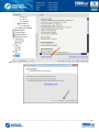
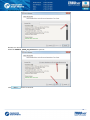
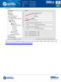
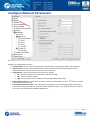
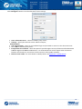
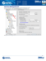
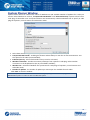
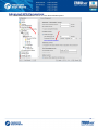
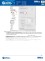
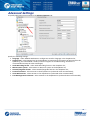
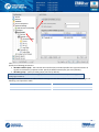
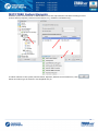
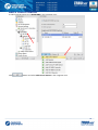
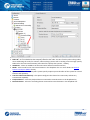
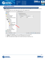
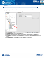
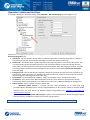
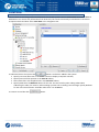
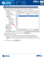
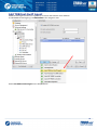
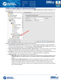
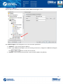
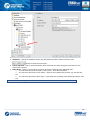
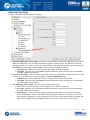
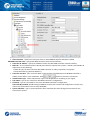
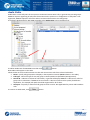
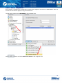
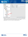
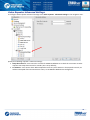
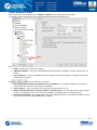
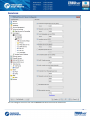
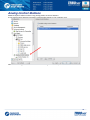
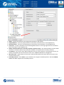
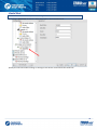
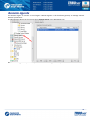
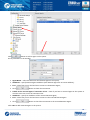
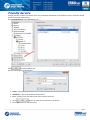
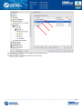
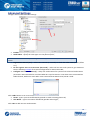
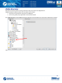
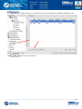
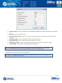
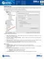
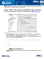
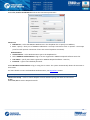
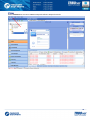
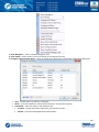
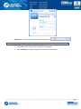
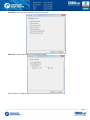
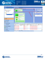
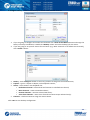
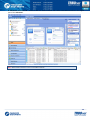
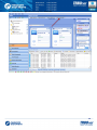
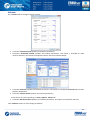
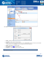
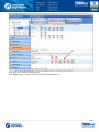
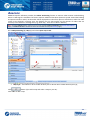
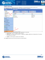
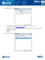
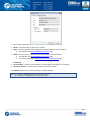
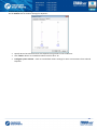
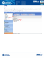
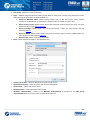
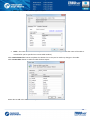
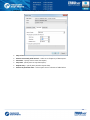
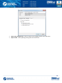
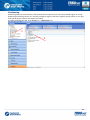
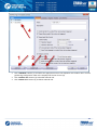
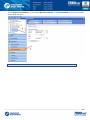
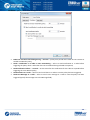
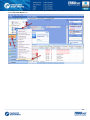
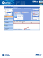
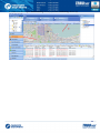
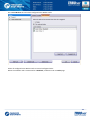
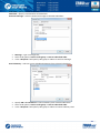
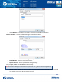
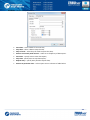
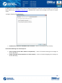
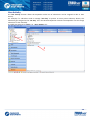
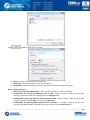
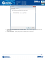
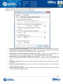
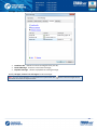
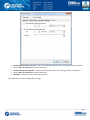
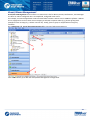
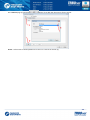
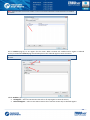
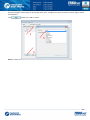
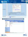
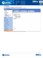
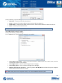
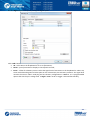
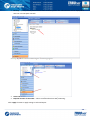
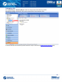
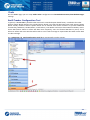
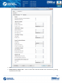
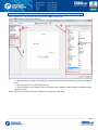
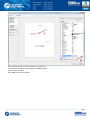
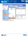
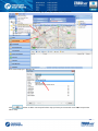
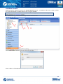
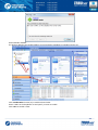
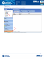
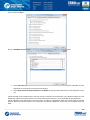
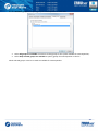
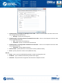
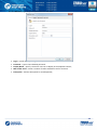
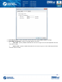
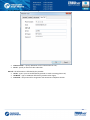
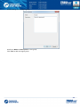
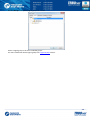
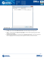
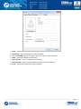
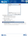
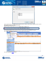
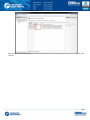
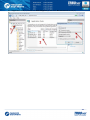
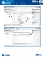
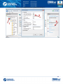
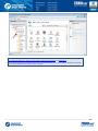
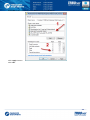
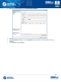
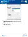
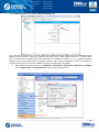
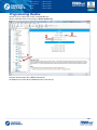
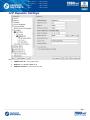
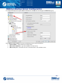
Hardware
Go to Hardware tab to configure USB devices, Proxy Server and active audio device options:
Enable external hardware support – select to use external hardware devices, e.g. cable connectors. Specify free
serial port on the PC for hardware devices.
 TRBOnet footswitch – select to enable TRBOnet footswitch.
Enable USB device – check to enable USB devices (e.g. USB connected microphones).
Connect a microphone to PC via USB device. Go to Tools , Options , Hardware. Check Enable USB Device.
 Device name – select microphone name in the dropdown list;
 PTT button – all available PTT buttons are represented in the dropdown list. Select PTT button in the
dropdown list and Press the PTT button on the microphone. When microphone PTT and PTT button in
Dispatch Console are set up correctly, Pressing Indicator becomes green.
 VoIP first port - port for audio communication. Specify VoIP first port (4022 set by default). Each
additional Dispatch Console will create connection to next port;
126
Use proxy server – select to enable Proxy Sever service in TRBOnet Dispatch Software to access Internet.
Click «Configure» button to set the alternative server settings:
 Use an alternate server – select to enable a proxy server;
 Settings – specify the alternate server address and port;
Authentication
 Use authentication – select to use individual login and password to connect to the alternate server.
Click «OK» to add the proxy server.
Configure audio devices
 Playback device - select the audio device for to play incoming voice messages and playback voice
recordings in Dispatch Console;
 Recorder device - select the recording device where the microphone is connected.
127
Advanced
Go to Advanced Tab to configure Dispatch Console Advanced settings:
Options PTT
 Send Alert Tone on extern PTT – select to enable Alert Tone for all subscribers on a channel when
Dispatcher presses PTT button;
 Use «Record Mode» on extern PTT – check to record all voice transmissions from external PTT devices
(palm mics, Footswitches etc.)
 Suggest TX Passive if channel is busy or subscriber radio is offline – select to record a TX Passive Voice
Message for a Radio channel is busy or subscriber is offline (see TX Passive configuration page);
 Enable «Short Press» PTT behavior (Semi PTT) – select to start and finish Voice Calls by short PTT
pressing instead of keeping PTT pressed during the whole Voice Call;
 Use «Space» for press PTT – select to set a key for press PTT. Click «Space» button to set a key. When
the informational message appears press any key on the keyboard to set it as PTT.
Options Voice
 Mute voice from other Dispatchers – select to mute all other Dispatchers’ voice transmissions;
 Mute voice from Private Calls – select to mute all Private Calls on the channel;
 Mute RX when transmit or record audio – select to mute all Voice Notifications when Dispatcher
transmits or records audio.
128
Options View
 Customize Radio display text – select to set a custom alias for Radio in the list of subscribers.
Click «Customize» button:
 Radio display name – specify a custom alias for selected radio;
 Allocated radio display name - specify a custom alias for selected radio in Allocation Console;
 Allocated radio display name (the owner has more than one radio) - specify a custom alias for selected
radio in Allocation Console in case when user has more than one radio.
Click
button to add more information about Radio:
 Radio Callsign – select to add a Radio Callsign;
 Radio Owner name – select to add an Owner name;
 Radio ID – select to add radio ID data;
 Active Channel – select to add an Active Channel for Radio.
Click «Default» button to set default settings for Radio Display.
129






Show extended nodes – select to enable extended nodes in the Dispatch Console;
Display confirmation dialogs – select to enable dialogs to confirm Dispatcher actions with Confirmation
dialogs required (e.g. send configured Voice Message from Dispatch Console);
Show incoming Text Messages in popup window – select to optimize incoming Text Messages view;
Minimize window on X-button click – select to use X-button to minimize Dispatch Console;
Measurement system – select Metric or American measurement system in the dropdown list.
Coordinate system – select coordinate system in the dropdown list. On Map – select to display
coordinates on the map.
130
Volume
Go to Volume Tab to configure Volume settings:
 Customize selected channel speakers and volume parameters;
 Customize unselected channel speakers and volume parameters. This option is intended for radio
channels which are not selected in Dispatch Console. See the screenshot below:
 Customize Intercom speakers and volume parameters. This option is intended for Intercom Voice session
between Dispatchers;
 Customize system sounds speakers and volume parameters ;
To see the list of system sounds go to Tools , Options , Sound Tab.
 Customize SIP Interconnect speakers and volume parameters. This option is intended for SIP calls;
Click «Default» button to reset settings to defaults.
131
Alarm
Go to Alarm tab to set radio in alarm mode indication settings:
Radio in alarm mode in new window – select to display radio in alarm mode centrally on the selected map type.
Click «Select Map» button to use online or offline map for radio displaying. For more details on supported
maps, see Map Types section.
Click «OK» to save modified Dispatch Console options.
132
Set Language
Select Tools , Set Language to change Dispatch Console’s language:
Select language in the dropdown list and click «OK».
The changes will apply with the next launch of console.
Change Password
Select Tools , Change Password to change the administrator’s password to access the Dispatch Console:
Type in old Password.
Type in New Password and then confirm it in the field below.
Click «OK» to change the password.
Help
Send feedback – click to see Neocom Software, Ltd. Contact details.
About – click to see your TRBOnet Dispatch Software info.
133
Route Management
Route Management feature allows create routs and assign to selected radio subscribers or dispatchers.
To create a route go to Route Management page (1):
134
Click «Create» button (2) to create new route:
 Name – specify a name to display in the route list;
 Description – add a description for new route.
Click «GPS Points» button (1) to add points to selected map:
Select map. For more details on map types see Map Types section.
135
Go to Route Points tab to set GPS Points, Beacons and Map Objects:
Click «Create» button or double-click selected point on the map to create new route point:





Name – specify a name for new point to display on the map;
Location – in the location field administrator can see current GPS coordinates of new point;
Radius – specify radius to display new point on the map;
Time – specify time to service new point;
Time delta – time inaccuracy to serve selected point.
Click «OK» to add new point.
136
Click «Beacons» (2) to add a beacon on the map.
Note: to enable Indoor feature make sure your license includes Indoor Positioning (see License Information
page) and Indoor Service is selected in the list of available services (see Services page ).
137
Click «Map Objects» button to download created map objects list:
Double-click selected object in the list to modify its settings:





Name – specify a name for the object;
Map Object – select map object icon (type) in the dropdown list;
Radius – specify radius to display the point on the map;
Time – specify time to service the point;
Time delta – time inaccuracy to serve selected point.
Click «OK» to save map object parameters.
All map objects are displayed as points on the map.
138
Go to Service Rules tab to manage point service settings:
Finish route – specify parameters to mark the route as finished:
 Finish route automatically if all points are serviced – select to mark the route as finished when all points
and objects are serviced.
Set point as serviced – select point service parameters:
 When radio enters to the point area – select to mark point as serviced when radio becomes in the point
radius;
 Manually by dispatcher – select to allow dispatcher make point as serviced;
 By condition when radio is in the point area – specify conditions to mark point as serviced:

Automatically by receiving Text Message from a radio - select to mark the point serviced after
dispatcher receives text message with specified text from radio subscriber;
Message – specify message text;

Automatically by receiving Telemetry Command from a radio - select to mark the point
serviced after dispatcher receives specified telemetry command from radio subscriber;
VIO – specify a VIO to send a telemetry command;
Command – specify a command for selected VIO;

Automatically by receiving DTMF command from subscriber – select to mark the point as
serviced after dispatcher receives DTMF command from radio subscriber;
Command – specify a command text.
139
Set point in alarm mode – select parameters to make the point in alarm mode:
 Automatically by receiving Text Message from a radio - select to make the point in alarm mode after
dispatcher receives text message with specified text from radio subscriber;

Message – specify message text;
 Automatically by receiving Telemetry Command from a radio - select to make the point in alarm mode
after dispatcher receives specified telemetry command from radio subscriber;

VIO – specify a VIO to send a telemetry command;

Command – specify a command for selected VIO;
 Automatically by receiving DTMF command from subscriber – select to make the point in alarm mode
after dispatcher receives DTMF command from radio subscriber;

Command – specify a command text;
 Automatically by receiving Emergency from subscriber – select to make the point in alarm mode after
dispatcher receives Emergency from radio subscriber;

Emg. Type – specify an Emergency type in the dropdown list;
140
Go to Notifications tab to manage notifications to radio:
Note: follow the predefined notifications templates. If text is not correct notifications will not be available.
 Send a Text Message on a route start – select to inform radio subscriber about route start;

Text Message – type in text message text to send to radio subscriber;
 Send a Text Message on a route finish – select to inform radio subscriber about route finish;

Text Message – type in text message text to send to radio subscriber;
 Send a Text Message when approaching the service time – select to notify radio subscriber about point
serve;

Time before service – specify a time period in minutes before service time to send a text
message;

Text Message – type in text message text to send to radio subscriber;
 Send a Text Message if point is not serviced – select to notify radio subscriber if the point is not serviced;

Text Message – type in text message text to send to radio subscriber;
 Send a Text Message if point is in alarm mode - select to notify radio subscriber if the point is in alarm
mode;

Text Message – type in text message text to send to radio subscriber;
Click «OK» to save settings.
141
New route is added in the route list (1):
Click «Start» button (2) to start the route:
 Name – specify a name for Active route;
 Start Date – select a date to start the route;
 Route – select route to start in the dropdown list. Click «Create Route» button to create new route based
on selected route. Click «Modify» button to modify selected route parameters.
 Radio – select Radio to assign the route;
 Radio Owner select Users to assign the route;
 Dispatcher – select a Dispatcher to monitor the route.
Note: do not select both: Radio and Radio Owner to prevent incorrect route running.
Click «OK» to start a route.
142
The route appears in the Active Routes list:
If the point is not served, it becomes red.
Click «Stop» button to replace active route in the Created routes list.
143
Administrator can see reports of finished routes. Go to Reports and Statistics (1) page and select Common
Reports – Finished Routes (2):
144
Radio Allocation
Selected radio can be assigned in the system to selected employee registered in the system.
All available radios are disabled and an employee will need to type in username and password to take and
enable selected radio. When an employee returns allocated radio it gets disabled again.
Go to Radio Allocation page (1) to assign radios to users:
Select radio in the list and click «Take/Return Radio» button (2):
 Radio – select radio to allocate;
 User – select User to allocate the radio. User should type in Dispatch Console or on the radio keyboard;
 Password –User should type the password in Dispatch Console or on the radio keyboard.
Note: for more details on user access to Allocation Console see Users section.
Click «Take Radio» button to assign the radio to selected User.
145
Administrator can see reports of allocated radios. Go to Reports and Statistics (1) page and select Common
Reports – Radio Allocation (2):
146
Beacons
TRBOnet Dispatch Software provides the Indoor Positioning feature to monitor radio location inside building,
where no GPS signal is available. The feature requires additional hardware (beacons spread around the building
and option boards in radios). A subscriber will be displayed on indoor floor plan on exact beacon when the radio
comes to the beacon's coverage area. The beacon icon on map notifies on the amount of radios that are
currently in this beacon's coverage area (e.g. Room 1(3) - there are 3 radios in Room 1).
Note: to enable Indoor feature make sure your license includes Indoor Positioning (see License Information
page) and Indoor Service is selected in the list of available services (see Services page ).
Go to GPS positioning (1) , Map (2) and select Open map in tab:

Map Type – select Beacon 2D to enable 2D floor plan or Beacon 3D to enable 3D floor plan (3);
Click
button (4) to add a map and select a map on your PC;
Click «OK» to add a map.
147
To add a beacon on selected floor plan click «Set Location» button (1) and specify new beacon properties (2):



Name – specify new beacon’s name;
Beacon ID – select your beacon ID;
Description – add a description for selected beacon.
148
To edit beacon’s parameters select beacon in «Objects» list:
Double-click selected beacon to edit parameters.
Note: for more details on beacons settings see the following article.
149
Administration
Go to «Administer» section to set system elements and options.
RadioServer
Go to Administer (1) , RadioServer (2) to see full system review:
150
Database
Go to Administer (1) , Database (2) to see full database overview:
On the Database Pane Administrator can restore and backup Database and Audio Recordings.
For more details on backups see Appendix D:
Database and Audio Recordings Backup and Restore
151
Radio Systems
All Radio Systems registered in the Server Configurator are represented on the Radio Systems Pane.
Go to Administer (1) , Radio Systems (2) to see system elements’ parameters:
Administrator can see the following Radio system parameters in the table:
 System Type – the list or registered radio systems;
 System ID – an unique System Identifier, configured in TRBOnet RadioServer configuration for repeater
of controllers of a system;
 Caption – channel type to transmit voice and data;
Click «Reset» button (3) to test the connection to system element.
152
Radio Systems Properties
To see radio systems properties do the following:
1. Select radio system in the list and click «Properties» button (1);
2. Double-click selected radio system in the list;
3. Right-click the selected element at the bottom of Dispatch Console window (2):
Administrator can see Active and Inactive registered systems. In case you have more than 10 registered
systems, systems are grouped and can be seen in the Dropdown list.
153
Common information for all system elements is listed below:
1. Description tab
On the Description tab see the general info:

System Type – system type for Repeater/digital or analogue mode for Control Station.
 For Repeater see MOTOTRBO Radio Systems page.
 System ID – an unique System Identifier, configured in TRBOnet RadioServer configuration for repeater
of controllers of a system;
 Caption – input channel name.
2. Channels
On the Channels Page see channel properties:
154
Click «Properties» button to see repeater additional data:






ID – default registration number (manufacturer’s number);
Name – system element’s name in the system;
Type – system type for Repeater/digital or analogue mode for Control Station.
 For Repeater see MOTOTRBO Radio Systems page.
Mode – system type for Repeater/connection mode for Control Station.
 For Repeater see MOTOTRBO Radio Systems page.
 For Control Station see Control Station Connection Modes page.
Connected
Serial number – default system element’s serial number (manufacturer’s number);
Firmware Version – current system element’s firmware version.
Click «Reset» button to test the connection to system element.
Note: For a repeater: «Reset» button reconnects the repeater.
For Control Station: «Reset» button reloads the radio.
155
Talk groups (For Repeaters only)
On the Talk groups tab see selected Talk group info:
Specify available Talk groups for the system element in the list of created Talk groups.
Selected Talk groups are available on Radio tab in the system element box in the dropdown list:
Note: close TRBOnet RadioServer Configurator before applying system elements’ settings.
156
Volume tab (for Repeaters only)
On the Volume tab see Volume settings for Repeater:



Specify RX and TX volume level for the Repeater using Volume control indicator.
Click «Reset» button to set default volume level for RX or TX.
Configure system volume – check to save default volume settings for Voice transmissions from selected
Repeater.
157
3. Transmits tab
On the Transmits tab see the information about audio and data transmissions:

Record audio – check to enable audio recordings for selected repeater;
158
System Bridging
TRBOnet Dispatch Software provides the System Bridging function. System Bridging allows configuring the
network to redirect calls.
Administrator can create two types of System Bridging:
4. System Bridging for Master Stations – allows connecting all types of Radios (analogue and digital
radios, supports IP Site Connect, Capacity Plus, Linked Capacity Plus and Connect Plus modes).
5. System Bridging for repeaters - allows connecting only repeaters in IP Site Connect mode.
Go to Administer (1) , System Bridging (2) to add a System Bridging in the system:
159
Click «Add» button to add a Cross Patch.
Select the System Bridging type in the dropdown list.
System Bridging for Master Radios:








Name – specify a name for System Bridging to display in Radio Interface;
Work mode – select work mode in the dropdown list. For more details on System Bridging for Master
Radios types see System Bridging Types page;
PTT Button – set PTT on the System Bridging interface to be able to transmit voice or do not set only to
hear the voice from other channel s. There are 3 options:
 Enable when System Bridging enabled
 Always enable
 Invisible
On the «Control Stations» tab select Control Stations and its parameters for Cross Patch.
Click «Add» button (1) to add a Radio in the list.
In the «Control Station» column select a radio in the dropdown list (2);
In the «Group» column select available group for the radio (3);
In the «Mode» column select a mode for the Radio (4).
 Select «Always» to enable System Bridging option always, regardless of radio status
(online/offline).
 Select «ByRadio» to enable System Bridging option on selected channel when there are online
radios capable to receive Voice Calls from selected group.
160
On the «Parameters» tab specify call types for System Bridging:
Check call types to use in System Bridging mode.
Click «OK» to add the System Bridging for Master Radios.
The System Bridging is displayed in Radio Interface:
161
System Bridging Types
1. Control stations redirect call to each other.
This is the most common type of System Bridging when data exchanges between the Control Stations set in the
System Bridging settings. Thus, there is a common channel for all the subscribers of the specified control
stations:
To create this mode of System Bridging add a System Bridging and set the Work Mode as Control stations
redirect the calls to each other.
Voice Call via System Bridging
MOTOTRBO
Capacity Plus
Analogue
Radio
network
Voice Call via System
Bridging
Capacity Plus
Control Station
TRBOnet
System
Bridging
Digital
Control Station
Digital Radio
network
Voice Call via System
Bridging
Analogue
Control Station
IP Site Connect
Control Station
Voice Call via System Bridging
MOTOTRBO IP
Site Connect
162
2. One control station redirects calls to many control stations.
Voice Call via System Bridging
Radio network
2
Control Station
TRBOnet
System
Bridging
Radio network
1
Control Station
Voice Call via System Bridging
Control Station
Radio network
N
To create this type of System Bridging add a System Bridging and set the Work Mode as One control station
redirects the calls to several Control stations.
163
3. Many control stations redirect calls to one control station.
Voice Call via System Bridging
Radio network
2
Control Station
TRBOnet
System
Bridging
Control Station
Radio network
1
Control Station
Radio network
N
Voice Call via System Bridging
To create this type of System Bridging add a System Bridging and set the Work Mode as Control stations
redirect the calls to one control station.
164
Binary Patch:
Name – specify a name for System Bridging to display in Radio Interface.
Rules – specify rules for System Bridging to redirect calls.
1 – Check Voice / Data to transmit on the selected slot;
2 – Select available Call types;
3 – Select available groups for System Bridging in the dropdown list;
4 – Select available repeaters to redirect calls in new System Bridging in the dropdown list.
The System Bridging is displayed in Radio Interface:
Note: System Bridging can be created in Radio Interface. It is a temporary System Bridging; it will be deleted
after reconnection to TRBOnet RadioServer or exit Dispatch Console.
165
Phone Calls
Go to Administer (1) , Phone Calls (2) to configure incoming and outgoing SIP calls:
166
Outgoing Calls Configuration
Click «Configure» button (3) to set Outgoing calls configuration parameters:









Allow subscribers to make outgoing calls – select to enable outgoing phone calls for subscribers;
Allow to use DTMF - check to allow radio subscribers to dial the phone number on the radio keyboard.
Allow to use Text Messages – select to enable Text Messages service in SIP Interconnect;
Prefix - a standard prefix for TMS Service (text messaging);
Backward call to radio – select mode to redirect phone call to radio in the dropdown list:
 After establish call – when a subscriber initiates a phone call to radio, the Dispatcher must
answer the call, after that the phone call will be redirected to a radio;
 Before establish call – when a subscriber initiates a phone call it will be automatically
redirected to a radio.
Initialize call to radio – select option to start a call to a radio.
 Start Transmission – select to start call to a radio automatically
 Send Ringtone – select to use beep tone until radio user presses PTT.
Send text message if cannot establish call – check if you want to receive text message when the
channel is busy during a phone call;
DTMF Access Code – set DTMF Access Code «0»
DTMF Deaccess Code - set DTMF Deaccess Code «#».
167
Incoming Calls Configuration
Click «Configure» button (4) to set Incoming calls configuration parameters:
 Call to Dispatch Center – select an option for input calls in the dropdown list:
 Decline calls – all input phone calls will be declined;
 Open Voice menu – when an input call starts the subscriber will hear Voice menu commands;
 Redirect to dispatchers – all input voice calls will be redirected to all dispatchers of the Dispatch
center and any free dispatcher will answer the phone call.
 Unknown Call – select mode to receive calls from unregistered subscribers:
 Decline Calls – select to cancel all calls from unregistered subscribers;
 Use number as Radio ID – select to allow system read unregistered number as Radio ID and
start Private Call;
 Use number as Internal – select to allow system read unregistered number according to Voice
Menu rules.
Extension numbers (Voice menu)
 Start call automatically – select to search the number in the table automatically. When the option is
disabled the subscriber must dial the number according to the following example: 0(phone number)#.
Character # used to search the phone number in the table.
 Max. number length – specify a max. phone number characters.
 Accept Code – used as handle to finish dialing number in Voice Menu.
All available numbers are listed in the table below (contact list) with number value and description.
Click «Add» button to add a number in the table.
168
To add a static number
Static number – numeric phone number:




Number – type in a phone number to add in the table (contact list);
Call Type – select a call type in the dropdown list;
Dispatcher – select a Dispatcher to make a phone call (for Dispatch Call). Radio – select a radio to make
a phone call (for Call Radio). Group - select a group to make a phone call (for Group Call);
Channel – select a channel to make a phone call (available for Group Call only).
To add a Dynamic number
Dynamic number – phone number with selected prefix:




Prefix – specify a prefix for phone calls to type in on the radio keyboard;
Call Type – select a call type in the dropdown list;
Radio/Group call – to make phone call to the selected radio/group the subscriber must type in radio
ID/Group ID on the keyboard
Channel – select a channel to make a phone call (available for Group Call only).
169
Tasks
Agenda
Agenda is used to automatically send predefined messages to the radios. It may be used when you have any
software receiving any messages but it is not able to send them to the subscribers. In this case TRBOnet
Dispatch Software acts like an intermediary - it receives the messages from the folder and sends them to radios.
To enable the tasks click «Add» button (1), «Agenda» (2):
170
Specify Agenda task settings:





Task name - specify the name to the task;
Outgoing folder (on server) - specify the outgoing folder for the text message to be displayed in the
Dispatch Console (e.g. C:\Outgoing);
Incoming folder (on server) - specify the incoming folder for the reports (e.g. C:\Incoming files);
Wait for response - specify the time interval for the response;
Text to confirm - specify the text to be sent by the subscribers after they receive the message.
171
Audio Recorder for NetCRR
Audio recorder feature allows connect to audio recorder NetCRR Digital Call Recorder via IP.
For more details on NetCRR Digital Call Recorder read User Manual:
To enable the tasks click «Add» button (1), «Recorder» (2):
172
The feature allows replicating audio recordings to the recorder:



Task name – specify a name for the task;
IP – type in recorder’s IP;
Port – specify recorder’s port.
Click «Test of channels» button to view all available channels on the recorder.
Click «OK» to add task.
173
Import Beacon Data from DB «Firebird»
Import beacon data from DB «Firebird» option allows import beacon data from Firebird database to TRBOnet
Dispatch Software database.
To enable the tasks click «Add» button (1), «Import beacon data from DB «Firebird» (2):
174
Settings – set mail connection to Firebird DB parameters:







Click
Name – specify a name for the task;
Server – select remote server or server on the local PC;
User – type in name of Firebird DB user;
Database path – specify Firebird DB path;
Password – specify a password to connect to Firebird DB (provided when logon);
Port – specify port to connect to Firebird DB;
Update (sec.) – specify update period for Firebird DB;
button to test the connection to Firebird DB.
Import – specify Import settings:

Import data from – specify Firebird DB name;



Click
button to import data;
Delete old data – select to delete previous imported data from Firebird DB;
Report – in the «Report» field import report will be displayed.
Click «OK» to add the task.
175
Export Data
TRBOnet Dispatch Software provides the Export Data function, which allows export data to an external database
table.
To enable the tasks click «Add» button (1) , «Export Data» (2):
176
Connection – set the connection settings.
 Task name - specify the name to the task;
 Type – TRBOnet Dispatch Software allows export data for third-party systems using data export tasks.
Select the type of data export in the dropdown list:
 Export to database table. Allows setting export data to MS SQL Server tables. Specify
connection to MS SQL Server parameters, database, base and table to export data.
 Export to Versa Trans. Allows export data to data collection system Versa Trans via IP. For more
details visit Versa Trans official website.
 Export to Google. Allows export data to file (file format is KML). For more details visit the
following website.
 Export to NMEA. Allows export data to file (text file format, export format is NMEA 0183). For
more details visit the following website
 Export to file. Allows export data to text file.
 Data – select the data to export in the dropdown list;





Default connection – select for default connection to SQL Server;
Specified connection – select to specify SQL Server and database;
Server name – specify SQL server name;
Database name – select a database from the list;
Windows authentication – select to use Windows authentication or unselect to use SQL Server
authentication (SQL Server user name and password required).
177

Data – specify a table and data types for export:

Table – the name of the table to be exported into external database (by default the name of the table is
created after you've specified it in Create table window).
Click «Load columns list» button to update the columns list in case you've made any changes in the table.
Click «Create table» button to add new table for data export:
Select data to add in the table and to export.
178

Scheduler – set schedule settings for data export:






Days of week – select days of week to export the data;
Execute recurrently with interval – select to set frequency of data export:
Start time – specify time to start data export;
Stop time - specify time to stop data export;
Repeat every – specify time period to export data;
Execute at particular time – select export time in columns of table below.
179

Advanced – specify advanced settings for location of the radio:


Export only changed data – select to export only changed location of the radio data.
Export mode - select updating existing and new records files.
180
Geofencing
Geofencing allows to control location and speed of radios respectively to manually specified regions on a map.
Geofencing monitoring consists of: manually configured regions and tasks. Regions specify where to use rules,
tasks specify how to rules for the regions and radios.
To enable a Geofencing task, go to «Tasks» (1) , «Geofencing» (2):
181
Administrator cans add/disable/delete rules for geofencing and edits current rules:



Click «Add Rule» button (1) and select the appropriate rule in the dropdown list to add a rule in current
geofencing configuration. New rule is displayed in the list of rules (4).
Click «Disable rule» button (2) to disable selected rule.
Click «Delete rule» button (3) to delete selected rule.
182
Variable settings for geofencing rules of event types (Map Region, Beacons, Radios and Lone Worker) are
represented in the table below:
Event type
Common Settings
Map Region.
Allows to configure
rules when radio(s)
enters or leaves
configured map
region(s).
Tab Name
General
Parameters Description
 Name – specify the rule's name;
 Description – add the rule's description;
Scheduler




Perform the rule on a schedule - click to start scheduler for geofencing rules;
Days of week - select the days to activate the geofencing rule;
Start time - set the time to start the rule;
Stop time - set the time to stop the rule.
Radios




All radios – select to apply this rule for all radios;
Only selected radios – select to apply the rule for one or several radios;
Select all – click to select all radios in the list;
Deselect all – click to deselect all radios in the list.
General
Scheduler
Regions. Select
regions to apply the
rule
Radios
Lone Worker.
Enables Lone
Worker when the
rule has been
triggered
 Regions Control – select to enable regions control;
 Control mode – select the control mode for regions in the dropdown list;
 Activate Alarm mode if the rule has been triggered – select to activate Alarm
mode in the Dispatch Console if Regions Control rule has been triggered;
 Send Text Message to a radio if the rule has been triggered – select to inform
radio subscriber if Regions Control rule has been triggered;
 Activate Lone Worker if the rule has been triggered – allows automatically
activating a Lone Worker policy for a radio in case of entering or leaving exact
region on map. Select to enable this option.
 Speed and Idle Control – select to enable speed and idle control;
 Control mode – select the control mode for speed and idle control in the
dropdown list;
 Maximum Speed – set the maximum speed for radio;
 Maximum Idle Time – set the maximum idle time for radio;
 Activate Alarm mode if the rule has been triggered – select to activate Alarm
mode in the Dispatch Console if Speed and Idle Control rule has been triggered;
 Send Text Message to a radio if the rule has been triggered – select to inform
radio subscriber if Speed and Idle Control rule has been triggered;
 Send Call Alert to a radio if the rule has been triggered – select to inform radio
subscriber if the rule has been triggered;
 Reset Alarm mode if the rule is not triggered - select to inform radio subscriber if the
rule has not been triggered;
See above
 All regions – select to apply this rule for all regions;
 Only selected regions – select to apply the rule for one or several regions;
 Select all – click to select all regions in the list;
 Deselect all – click to deselect all regions in the list.
See above
 All Tasks – select to apply all tasks, configured by Administrator, when the rule has
been triggered;
 Only selected tasks – select to enable Lone Worker task, configured by Administrator
when the rule has been triggered.
183
Beacons.
Allows to configure
rules when beacon
(s) enters or leaves
coverage zone
General
Scheduler
See above
Radios
See above
Beacons.
Enables rule for
selected beacons
Lone Worker
Radios.
Allows use
radio(s)1 as a map
region and monitor
when another
radio(s) enters or
leaves radio’s
coverage zone
 Control mode:
 Control entering beacon coverage zone – select to enable the rule when a radio
enters beacon coverage zone;
 Control leaving beacon coverage zone - select to enable the rule when a radio
leaves beacon coverage zone;
 Activate Alarm mode if the rule has been triggered - select to activate Alarm mode in
the Dispatch Console if Beacons rule has been triggered;
 Reset Alarm mode if the rule is not triggered – select to reset Alarm mode in the
Dispatch Console automatically if the rule condition was not triggered (e.g., when
«Control entering beacon coverage zone» selected and radio enters to the monitored
coverage zone and then instantly leaves the zone, alarm mode in the Dispatch Console
will be reseted automatically)
 Send Call Alert to a radio if the rule has been triggered – select to inform radio
subscriber if the rule has been triggered;
 Send Text Message to a radio if the rule has been triggered – select to inform radio
subscriber if Beacons rule has been triggered;
 Activate Lone Worker if the rule has been triggered – allows automatically activating a
Lone Worker policy for a radio in case of entering or leaving beacon coverage zone.
Select to enable this option.
General
Scheduler
Regions
Radios
 All Beacons – select to apply this rule for all beacons;
 Only selected beacons – select to apply the rule for one or several beacons.
See above.
 Control mode:
 Control Entering Region – select to enable the rule when a radio enters the
coverage zone associated with another radio;
 Control Leaving Regions - select to enable the rule when a radio leaves the
coverage zone associated with another radio;
 Activate Alarm mode if the rule has been triggered - select to activate Alarm mode in
the Dispatch Console if Radios rule has been triggered;
 Reset Alarm mode if the rule is not triggered – select to reset Alarm mode in the
Dispatch Console automatically if the rule condition was not triggered (e.g., when
«Control Entering Region» selected and radio enters to the monitored coverage zone
and then instantly leaves the zone, alarm mode in the Dispatch Console will be reseted
automatically)
 Send Text Message to a radio if the rule has been triggered – select to inform radio
subscriber if Radios rule has been triggered;
 Send Call Alert to a radio if the rule has been triggered – select to inform radio
subscriber if the rule has been triggered;
 Minimum distance between radios – select a distance in meters. When the distance
less than selected value, the rule will be triggered according to settings above.
 Color of region – select radio coverage zone color.
See above
Select radio coverage zones the rule is applied for.
See above
184
Lone Worker.
Allows configure
scheduled Lone
Worker task
General
Radios
Lone Worker
 Days of week - select the days to activate the Lone Worker rule;
 Start time - set the time to start the rule;
 Stop time - set the time to stop the rule.
See above
Select all configured by Administrator Lone Worker tasks or several configured tasks.
When Lone Worker task is mentioned as «Disabled», Administrator should enable the
task.
185
Idle Time
Idle Time feature allows monitor vehicles idle time assigning Telemetry Commands on selected VIOs.
To enable the task go to «Tasks» (1) , «Idle Time» (2):
Specify the telemetry to set the Idle Time:
Start:
 Specify the telemetry VIO and command to start the Idle Time;
Stop:

Specify the telemetry VIO and command to stop the Idle Time.
186
Administrator can see Idle Time reports and statistics.
Go to «Reports and Statistics» (1) and select Idle Time summary or Idle Time detailed (2) to see the common
report about Idle Time:
Note: specify speed accuracy value in «Speed» field.
187
Lone Worker
The Lone Worker policy lets the Dispatcher set a time interval the communication with a subscriber is expected.
For example, if a lone worker has not called the Dispatcher for 15 minutes, the radio receives a message and the
Dispatcher receives an al arm signal.
To enable the task go to «Tasks» (1) , «Lone Worker» (2):
188
Task start – specify Lone Worker task start properties:




Manually (on demand of Dispatcher) – select to start Lone Worker task manually;
Automatically by receiving Text Message from a radio – select to start Lone Worker task after receiving
a message (specify the message text in the Message field);
Automatically by receiving Telemetry Command from a radio – select to start Lone Worker task after
receiving telemetry. Specify VIOs (1 to 5) and the Command;
Automatically by receiving DTMF command from subscriber – select to start Lone Worker task after
receiving a predefined DTMF command (specify the command in the Command field).
189
Conditions – specify alarm mode settings for Lone Worker:





Radio has not been transmitting during … minutes – specify time period when radio do not transmit to
enable Lone Worker policy;
Send a notification to a radio to start transmitting – select to send notification to a radio before
triggering the policy when a subscriber has not transmitted during selected time period;
Send notification before ... seconds – set the time after the notification for the radio to respond before
triggering the Lone Worker policy;
Send Call Alert to a radio – select to send a call alert to a radio in case the policy has been triggered;
Send Text Message to a radio – select to send a text message to a radio in case the policy has been
triggered (specify the message text in the Message field).
190
Task stop - specify Lone Worker task stop properties:




Manually (on demand of Dispatcher) – select to stop Lone Worker task manually;
Automatically by receiving Text Message from a radio – select to stop Lone Worker task after receiving
a message (specify the message text in the Message field);
Automatically by receiving Telemetry Command from a radio – select to stop Lone Worker task after
receiving telemetry. Specify VIOs (1 to 5) and the Command;
Automatically by receiving DTMF command from subscriber – select to stop Lone Worker task after
receiving a predefined DTMF command (specify the command in the Command field).
191
To enable Lone Worker feature for selected Radio go to Radio section (1), right-click selected radio (2) and
select Start Lone Worker (3):
192
To monitor Lone Worker task go to Active Tasks tab:
193
To enable Lone Worker go to GPS Positioning section (1) and click «Geofencing» button (2):
194
Select Add Rule – Lone Worker (1):
Select Name for Lone Worker rule and add description.



Days of week - select the days to activate the Lone Worker rule;
Start time - set the time to start the rule;
Stop time - set the time to stop the rule.
195
Go to Radios tab and add radios to apply Lone Worker rule:




All radios – select to apply this rule for all radios;
Only selected radios – select to apply the rule for one or several radios;
Select all – click to select all radios in the list;
Deselect all – click to deselect all radios in the list.
196
Go to Lone Worker tab and select configured Lone Worker tasks:
Select all configured Lone Worker tasks or several configured tasks.
When Lone Worker task is mentioned as «Disabled», enable the task on Tasks page.
197
Radio Allocation (Sprite Forms)
This function is used f or direct communication between the Dispatcher and the subscriber via special Tallysman
Option board installed into the radio. Dispatcher and subscriber have special form templates. Dispatcher
receives Duty ID of the subscriber with his template output form whereas the subscriber sends it using template
input form. Radio name changes to its Duty ID.
Note: any activity may be decoded with its Duty ID so it is the way to communicate for Dispatcher and
subscribers only.
To enable the task go to «Tasks» (1) , «Radio Allocation (Sprite forms)» (2):
198
Load the Sprite Form (output template) and select the Field Name:
Click «OK» to add a Sprite Form.
199
Scheduled Task
This function allows sending scheduled messages to radios.
To enable the tasks click «Add» button (1) , «Scheduled task» (2):
200
Task name – specify a name for the task.
Command – specify a command for scheduled task.
Send text message – select to send text message to selected subscribers:



Message – type in message text;
Select send options: send to radio group or send to subscribed radio.
In the «Recipient» field specify radio group or radios to send text message.
Send Telemetry – select to receive scheduled telemetry from selected subscribers:



Specify VIO and Command to receive telemetry from selected subscribers.
Select send options: send to radio group or send to subscribed radio.
In the «Recipient» field specify radio group or radios to receive telemetry data.
201
Request location – select to receive selected radios location data:

In the «Recipient» field specify radio group or radios to receive radio’s location data.
Send voice message – select to send voice message to selected subscribers:



Load from file - choose to load an existing file from your PC;
Record Message - choose to record new message;
Playback message - choose to playback an existing message.
Specify call type, channel and call target for voice message:
Note: to send a Voice Message to a subscriber from a phone book click
and select the contact in the phone book.

button in the Call Target column
Impolite channel access - the radio will always transmit when the Push-to-Talk (PTT) button is pressed
(not available in a Capacity Plus Personality channel).
202
Scheduler – set scheduler parameters:








Start date – select a date to start the task;
Stop date – select a date to stop the task;
Days of week – select days of week to export the data;
Execute recurrently with interval – select to set frequency of data export:
Start time – specify time to start data export;
Stop time - specify time to stop data export;
Repeat every – specify time period to export data;
Execute at particular time – select export time in columns of table below.
203
SMS and Email Notifications
TRBOnet Dispatch Software allows manage text messages:
1. Send Text Messages from LAN to a particular radio or talk group (POP3 Server);
2. Forward all Text Messages from radios to base radio to particular email address (SMTP Server).
Note: Microsoft Exchange Server can be used as SMTP and POP3 servers. For more details on SMTP or POP3
servers ask your System Administrator.
To enable the task go to «Tasks» (1) , «SMS and Email notifications» (2):
204
SMS settings - set parameters for SMS sending:


Send SMS to recipients if ALARM has been activated – select to send SMS in case of Alarm on the
radio;
Send MMS to recipients if ALARM has been activated – select to send MMS in case of Alarm on the
radio;
Forward Text Messages to cell phone recipients
 Input messages (from radio network to Dispatchers) – select to forward incoming text messages to cell
phone;
 Output messages (from Dispatchers to radio network) – select to forward outgoing text messages to
cell phone;
For more details on sms settings go to
205
Outgoing email settings (SMTP)
A radio sends text messages to base station. TRBOnet RadioServer forwards all text messages to a particular
email address (e.g. [email protected]). Administrator receives text messages from radios as regular
emails.
Configure outgoing email parameters:

Send Email to recipients if ALARM has been activated – select to send Email in case of Alarm;
Forward Text Messages to email recipients


Input messages (from radio network to Dispatchers) – select to forward incoming text messages to
Email address(es);
Output messages (from Dispatchers to radio network) – select to forward outgoing text messages to
Email address(es);
206
Incoming email settings (POP3)
Sending emails to a dedicated email address (e.g. [email protected]).
TRBOnet RadioServer connects to POP3 server, reads emails and sends text messages to radios or talk groups.
1. Create an email account on your email server.
2. Send an email to [email protected]. In the «Subject» field type in Radio ID: XXX to send
an email to selected radio or Group ID: XXX to send an email to selected radio group.
Note: If you did not specify the «Subject» of email properly or specify not existing RadioID, you will see an
appropriate notification in the Event Log of Dispatcher Console.
Configure incoming email parameters:

Forward incoming emails to radio network (from email box to radios) – select to forward incoming
emails to radio network;
207
User Activity
The User Activity function allows the Dispatcher make lists of subscribers can be assigned to due to their
activity.
For example, if a subscriber sends a message “On duty” or presses an exact preset telemetry button, this
subscriber gets assigned to the “On duty” list in the Remote Dispatcher Console. The Dispatcher can also assign
subscribers to lists manually.
To enable the tasks go to «Tasks» (1) , «User Activity» (2):
208
Lists of radios – configure lists of radios parameters:
Click



button to add new lists of radios:
Name – specify a name for new user activity list;
Description – add a description for new user activity list;
Background – select the background color to display the subscribers assigned to the list;
Move a radio to this list if:
 Manually (on demand of Dispatcher) – select to assign subscribers to the list manually;
 Automatically by receiving Text Message from a radio – select to assign a radio to the list after
receiving a message (specify the message text in the Message field);
 Automatically by receiving Telemetry Command from a radio – select to assign a radio to the list after
receiving telemetry. Specify VIOs (1 to 5) and the Command;
 Automatically by receiving DTMF command from subscriber – to assign a radio to the list after
receiving a predefined DTMF command (specify the command in the Command field).
209
To assign an offline subscriber to the default User Activity list, go to the Advanced tab:


Automatically set the default status for offline radios – select to allow assign the default status for
offline radios;
Set the default status – specify time period to set default status to a subscriber.
210
Voice Message
The Voice Message allows automatically broadcasting a predefined Voice Message after receiving telemetry, a
text message or a DTMF command.
To enable the tasks go to «Tasks» (1) , «Voice Message» (2):
211
Click «Add» button to add a voice message task. The user can have several Voice Message policies for different
purposes. Specify the name of the policy in the Task name field and set the policy's parameters.
Task start – set parameters to control the start of the policy:







Manually (on demand of the Dispatcher) - select to allow the Dispatcher start Voice Message manually;
Automatically by receiving Text Message from a radio – select to start Voice Message after receiving a
message from a subscriber (specify the message text in the Message field);
Automatically by receiving Telemetry Command from a radio – select to start Voice Message after
receiving telemetry: set the telemetry VIO (1 to 5) and the Command (High, Low or Pulse);
Automatically by receiving DTMF command from subscriber – select to start Voice Message after
receiving a DTMF command from radio subscriber (specify the command in the Command field, e.g.
1221);
Activated by any radio – filter to receive data for enabling task. Select to receive data from any radio in
the system;
Activate by specific radios only - filter to receive data for enabling task. Select to receive data from
selected radios in the system;
Send Text Message to a radio – select to notify with a text message when Voice Message starts (specify
the message text in the Message field);
212
Task Process – specify Voice Message transmitting parameters:



Send Voice Message once – select to send voice message to a selected radio (s) once;
Send Voice Message repeatable - specify Repeat Interval and Repeat Count if you need to send Voice
Message more than once;
Impolite channel access - the radio will always transmit when the Push-to-Talk (PTT) button is pressed
(not available in a Capacity Plus Personality channel).
213
Task stop – set parameters to control the stop of the policy:





Manually (on demand of the Dispatcher) - select to allow the Dispatcher stop Voice Message manually;
Automatically by receiving Text Message from a radio – select to stop Voice Message after receiving a
message from a subscriber (specify the message text in the Message field);
Automatically by receiving Telemetry Command from a radio – select to stop Voice Message after
receiving telemetry: set the telemetry VIO (1 to 5) and the Command (High, Low or Pulse);
Automatically by receiving DTMF command from subscriber – select to stop Voice Message after
receiving a DTMF command from radio subscriber (specify the command in the Command field e.g.
2112);
Send Text Message to a radio – select to notify with a message when Voice Message starts (specify the
message text in the Message field).
214
Message – specify Voice Message file parameters:



Load from file - choose to load an existing file from your PC;
Record Message - choose to record new message;
Playback message - choose to playback an existing message.
Specify call type, channel and call target for voice message:
Note: to send a Voice Message to a subscriber from a phone book click
and select the contact in the phone book.
button in the Call Target column
215
Telemetry – set telemetry transmission options:





Send telemetry before start task – select to send telemetry before voice message will be transmitted.
Specify VIO and Command to send the telemetry.
Send telemetry after stop task – select to send telemetry after voice message will be transmitted.
Specify VIO and Command to send the telemetry.
Recipient – select the radio to send the telemetry.
Click «OK» to save voice message policy settings.
216
Event/Alarm Management
Event/Alarm Management feature allows to create action rules for Alarms, Emails, Notifications, Text Messages
to radios etc. When configured rule is accomplished, configured action starts.
For example, an external application sends text data which contains «alarm» text to TRBOnet software. «Alarm»
text is configured as a rule to start voice messaging to selected recipients radios (e.g. firemen group) with
predefined voice message (e.g. «Alarm in Sector N»). Finally, firemen group is notified about emergency
condition.
Go to Administer (1) , Event/Alarm Management (2) to set Event/Alarm Management:
Click «Add» button (3) to add new Event/Alarm Management configuration.
217
Go to Source page (1) and click
button (2) to add new data source for the action:
Event – select event in the dropdown list to set it as a rule for an action (3).
218
Variable settings for event source see in the table below:
Event Type
Parameters Description


Text Message



Telemetry



DTMF


COM Port
External Network
Connection
Activated by any radio – filter to receive telemetry data from any radio in the system to enable the
action;
Activate by specific radios only - filter to receive telemetry data from selected radios in the system to
enable the action;
VIO – select VIO to send telemetry;
Command – specify a command for selected VIO.
Activated by any radio – filter to receive DTMF command from any radio in the system to enable the
action;
Activate by specific radios only - filter to receive DTMF command from selected radios in the system to
enable the action;
Command – specify DTMF command to start an action.


COM Port – select COM Port connection configured in Server Configurator;
Regular Expression – specify the text or digits the data from external application should contain to start
an action, selected on Action page. For more details on regular expressions see wiki article.


Connection – select connection configured in Server Configurator on TCP/IP page;
Regular Expression – specify the text or digits the data from external application should contain to start
an action, selected on Action page. For more details on regular expressions see wiki article.


Activated by any radio – filter to receive an alarm from any radio in the system to enable the action;
Activate by specific radios only - filter to receive an alarm from selected radios in the system to enable
the action;
Alarm – select alarm type in the dropdown list.

Emergency Alarm – alarm configured in radio Code Plug;

Man Down – subscriber positioning monitoring;

No Movement – subscriber movement monitoring;

Crash Detect – subscriber speed and sudden stop monitoring;

Geofencing - control location and speed of radios respectively to manually specified regions
on a map.

Alarm


Radio State
Activated by any radio – filter to receive text messages with predefined text from any radio in the
system to enable the action;
Activate by specific radios only - filter to receive text messages with predefined text from selected radios
in the system to enable the action;
Text Contains – specify the text or digits text messages from radios should contain to start an action,
selected on Action page.


Activated by any radio – filter to receive radio state data from any radio in the system to enable the
action;
Activate by specific radios only - filter to receive radio state data from selected radios in the system to
enable the action;
Radio is detected as online – when radio state «Online» comes, the action starts;
Radio is detected as offline - when radio state «Offline» comes, the action starts.
219
Note: check the event you want to enable. In case no one event selected all configured events are disabled
by default:
Go to Location page (1) to set regions for the action. When Location rule enabled and a region is selected
events, mentioned on Source page should take place in the selected region to start the action.
Note: when source event COM Port and/or External Network Connection selected, Location rule should not
be used.
Check «Enable» (2) to apply Location rule to the action.
 All Regions – select to use Source Event rule in all map regions to start the action;
 Selected Regions – select to use Source Event rule to start the action only in selected regions.
220
Go to Action page (1) to set actions for Source Event and Location rules. In the Actions list Administrator can
add and configure action types to be started when rules, configured on Source and/or Location pages, will be
accomplished.
Click
button (2) to add an action:
Action – select action type in the dropdown list (3).
221
Variable settings for the Actions see in the table below:
Action Type
Alarm
Email
Job Ticket
Parameters Description
Not applicable.
 Recipients – select email recipients in the dropdown list;
 Text – type in email text to send to recipients;
 Variables – Administrator can add Variables to include in the email text:
 Radio ID – Radio ID data will be included in the email text
 Radio Name – Radio Name will be included in the email text
 Radio State on/off – Radio State data will be included in the email text
 Beacon Name – Beacon Name will be included in the email text (if beacons are used in the
system)
 Alarm – Alarm Type will be included in the email text
 Street Name – Street Name will be included in the email text (available when Use
MapPoint location resolving option selected for Enhanced GPS)
 Map Link – Link to radio current location on Google Maps will be included in the email
text
 Region – region name will be included in the email text.
 Incoming Text Data – all incoming text data (e.g. COM port devices and External Network
Connection data, text messages) will be included in the email text.




Deadline – select task end time;
Recipients – Administrator can select radios or radio groups registered in the system;
Description – add Job Ticket description;
Variables – add variables to include in Job Ticket description.

Severity – select severity level in the dropdown list:
 Information – select to set low severity level
 Warning – select to set middle severity level
 Alarm – select to set high severity level.
Text – add text in the notification to display in the Dispatch Console;
Variables – add variables to include in Notification.
Notification


Request Location
SMS
System Bridging
Telemetry
Text Message
Not applicable.

Recipients – select sms recipients in the dropdown list;
 Text – type in sms text to send to recipients;
 Variables – Administrator can add Variables to include in the sms text.


Profiles – select System Bridging profile to activate/deactivate;
Activate/deactivate – select action type for System Bridging pro file.



VIO – select VIO to send telemetry;
Command – specify a command for selected VIO;
Recipients – select Radios or Radio Groups to send telemetry.



Recipients – select text message recipients in the dropdown list;
Text Message – type in message text to send to recipients;
Variables – Administrator can add Variables to include in the message text.
222
Text to speech feature allows convert text to speech:
Text to Speech
Voice Message




1 – click «Add» button to add new text to covert to speech;
2 – Configure Call Type, Channel and Call Target to send text converted to speech.
Text – type in text to convert to speech.
Variables - Administrator can add Variables to include in the message converted to
speech.

Voice Messages – select recorded voice messages. For more details on Voice Messages
see Tasks , Voice Message section.
Note: After configuring check rules you want to enable in the list. In case when no one rule is selected, the
action will not be started:
223
Telemetry
On the «Telemetry» page you can configure Telemetry.
Go to Administer (1) , Telemetry (2) to manage Telemetry properties:
224
Radio Groups Telemetry
Go to «Radio Groups Telemetry» to manage telemetry profiles for radio groups:
225
Click «Add» button to add a telemetry profile for Radio Groups:
Specify Telemetry Type for Radio groups:
 Mototrbo – telemetry from Motorola devices.
 Novox – telemetry from Novox devices connected to radio via COM port.
 Swift.Tracker – telemetry from Swift.Tracker sensors. Swift.Tracker connects to radio over-the-air.
 Sprite – telemetry from Sprite devices.
Note: Sprite telemetry profile can be read but not written.
Specify profile name to display in the Dispatch Console.
Click «OK» to add a telemetry profile.
Specify new telemetry profile settings.
On the Common tab specify common settings for new profile:




Auto request input states – select to set time interval to request input data. Specify time period in
seconds (600 seconds set by default);
Trace digital inputs – select to monitor digital inputs’ damages;
Trace analog inputs – select to monitor analog inputs’ damages;
Replace state event to VIO events – select to generate VIO ON/OFF event when the system compares
the last and the current state of the VIO.
Note: Most of the policies are set to replace events, so it is recommended to enable this option.
226
On the «Digital Inputs» tab specify settings for digital inputs:
Click «Add» button to set VIO (Virtual Configured PIN):
 ID – select VIO in the dropdown list to set its parameters;
 Name – specify VIO name to display in the Dispatch Console;
 Event – a filter for telemetry events. Select the signal level of VIO events in the dropdown list. When any
event with selected signal level takes place on the selected VIO, the telemetry activates. The signal level
must be the same in radio’s code plug and in Telemetry configuration in TRBOnet. It is a programmable
option that sets the pin's voltage level to High or Low in order to trigger a selected functionality;
227

Severity – specify severity level for VIO event in the dropdown list. Selected icon will be displayed as
VIO icon in the Dispatch Console:

Display as the Subscriber state – go to Telemetry page to see selected radio telemetry data:


Auto reset state - select to reset the telemetry VIO automatically;
Request location of subscriber – select to enable subscriber GPS positioning.
Click «Apply» button to apply settings to selected inputs.
228
On the «Digital Outputs» tab specify settings for digital outputs:
Click «Add» button to set VIO (Virtual Configured PIN):
 ID – select VIO in the dropdown list to set its parameters;
 Name – specify VIO name to display in the Dispatch Console;
 Command – specify a command for selected VIO in the dropdown list.
Click «Apply» button to apply settings to selected inputs.
The profile is added in the navigation tree:
Note: For editing telemetry profile for Radio Groups only «Digital Outputs» tab available.
229
Telemetry #N
Go to Telemetry (1) , Telemetry #N (2) to add and configure personal Telemetry profiles.
All telemetry profiles configured in the system are displayed in the Navigation Tree:
To add and edit personal telemetry profiles follow the steps as described in Radio Groups Telemetry page.
230
Tools
On the «Tools» page you can setup Swift.Tracker configurations and Extended Comments/Extended Messages
settings.
Swift.Tracker Configuration Tool
In general, a MOTOTRBO™ portable radio comes with a standard option board factory- installed to the radio.
Generic Option Board replaces this standard option board, new radio like XPR 7550 come with Generic Option
Board already installed. Generic Option Board can be flashed with custom firmware to provide additional
functionality: ManDown, No Movement, Crash Detect, Lone Worker and event-driven GPS functionality. Eventdriven GPS feature allows to collect GPS data more frequently, store and forward GPS data by event, also it
allows to collect and store GPS data while radio is out of radio coverage to request GPS data when comes back
to radio coverage.
Go to Administer (1) , Swift Configuration Tool (2) to manage Swift.Tracker settings:
231
Click «Add» button to add configuration for Swift Tracker.
 Name - select name for configuration to apply it to radio or group of radios;
 Description - add description for configuration;
Click «Set Defaults» button - select to enable default settings for GOB.
On «General» page set general settings for Swift Tracker:
Modules
 Enable GPS Tracker- when GPS enabled radio sends data to TRBOnet RadioServer according individual
GOB settings.
 Enable "No Movement" Alarm - select to enable No Movement feature;
 Enable "Man Down" - select to enable Man Down feature.
General report
 Report period (sec.) - select time period for data transfer to the server;
 Number of retries - specify the number of retries when data transfer is impossible. If the channel is busy
data transfer to the server is priority and TX Interrupt feature will be enabled automatically;
 Retry delay - select time period between data transfer retries.
232
Radio settings
 Network radio ID (CAI ID) - select your RadioServer PC network radio ID. ID=13 is a default value to
route packet to RadioServer PC, value 12 will send packets to a control station.
 Target Radio ID - select target radio ID for data transfer. In case of direct connection to repeater select
the TRBOnet server ID (TRBOnet peer ID).
 Port - select port for data transfer.
Automatically Switch to Revert Channel - select to transfer data via revert channel in automatically mode.
Note: if radio does not have a revert channel this option must be disabled.
233
Go to «GPS Tracker page» to set GPS Tracker settings:
GOB data Storage
 Save GPS data on passing distance every (m) - specify the distance. When the indicated distance is
passed radio saves the data in Option Board memory but GPS data are not added in the report;
Adding data to report
 Speed and Direction - select to receive radio speed and direction data;
 Add data to report every (m) - specify the distance. When indicated distance is passed radio adds data
to the report. At this case the data is saved in the report to send the report according to selected time
period (see «Report Period » option).
Note: Number value Add data to report every (m) must exceed number value Save GPS data on passing
distance every (m).


Minimal direction angle - select minimal direction angle to add data to the report automatically (if the
radio reverses the direction the current data is added to the report automatically and next data
recording is started).
Add data to report every (sec.) - specify time period for the report. When the indicated time period is
passed radio adds the data to the report.
234
Report transmit conditions (custom report settings)
 Report period (sec.) – set time period to send the report;
 Passed distance is more than (m) - type in the distance. When the indicated distance is passed the
Option Board sends the report.
Note: Number value Add data to report every (m) must exceed number value Save GPS data on passing
distance every (m).


Speed exceeds - select speed. When current speed is more than the indicated one, radio sends data to
the TRBOnet Dispatch Software server;
Stop/Idle Time is more than (sec.) - select stop/idle time. When stop/idle time is more than the
indicated one radio sends data to TRBOnet RadioServer.
235
Go to «Tasks» page to set Man Down, No Movement, Lone Worker and Crash Detect settings:


Activate the accelerometer on the radio switching on - select to enable accelerometer;
Disable alarm by button click – select to allow radio subscriber disable alarm notification by pressing
any button on the radio.
236
"Man Down" settings
 Activation angle - select activation angle to enable Man Down feature;
 Pre-Alarm (1) Timeout (sec.) - select time period preceding pre-alarm Tone 1;
 Pre-Alarm tone (1) - select pre-alarm tone. All pre-alarm tones can be found in radio’s code plug
configuration.
"No Movement" Settings
 Vibration Threshold (%) - select max. vibration threshold for No Movement feature;
 Pre-Alarm Timeout (sec.) - select time period preceding pre-alarm Tone 1;
 Pre-Alarm tone - select pre-alarm tone. All pre-alarm tones can be found in radio’s code plug
configuration.
«Lone Worker» Settings
 Timeout (sec.) – select time period to enable Lone Worker alarm;
 Pre-alarm tone - select pre-alarm tone. All pre-alarm tones can be found in radio’s code plug
configuration;
Second Pre-Alarm Notification. When pre-alarm tone (1) activates for Man Down, No Movement and Lone
Worker, and there was no user’s activity (the radio remains unchanged), the second pre-alarm tone activates:
 Timeout (sec.) - select time period preceding pre-alarm Tone 2;
 Pre-Alarm tone - select pre-alarm tone. All pre-alarm tones can be found in radio’s code plug
configuration;
 Volume Level Increase (%) - select the percentage of the Volume Level Increase for pre-alarm Tone 2;
 Pre-Alarm Duration (sec.) - select pre-alarm Tone 2 duration.
«Crash Detect» Settings:
 Crash Threshold (g) - select acceleration changing value to enable Crash Detect alarm notification;
 Movement Stop Timeout – select the time period of movement stop to enable Crash Detect alarm
notification;
 No Movement Timeout - select the time period of the radio without any movement to enable Crash
Detect alarm notification;
Emergency call
 TRBOnet Emergency Timeout (sec.) - select time period preceding emergency tone to the Dispatch
Console for Man Down, No Movement and Lone Worker options;
 MOTOTRBO Emergency timeout (sec.) - select time period preceding emergency tone to the Dispatch
Console.
Note: MOTOTRBO Emergency Alarm should be set in Radio’s code plug.
Sound notification after emergency call
 Timeout (sec.) – select time period to repeat the alarm notification. To stop the alarm notification
Dispatcher should disable alarm notification;
 Tone – select the notification tone. All tones can be found in radio’s code plug configuration.
Click «Set defaults» button to apply default values.
Click «Import» button to import Swift .Tracker configuration from file.
Click «Export» button to save Swift .Tracker configuration as file to the PC.
237
Go to «Input Pins» page to set the priority for Enabled/Disabled Pins:
Select programmed Pin in Enabled/Disabled Pins table.
Select data transmission priority for Pin:
 Deferred - to send the data into current packet;
 In Memory - to save the data in the GOB memory;
 Immediately - transmission interrupt - oriented. Select Immediately to transmit the data via free
channel with radio channel priority;
 Extremely - transmission via radio channel and GSM channel simultaneously.
The PIN options are model dependent. All available PINs for the radio can be programmed in Radio’s codeplug
configuration (See Accessories , GPIO Physical PINs)
Note: additional PINs are available when GSM Swift.Tracker connected only. For more details contact
technical support.
Click «OК» to save the settings.
238
Templates for Extended Messages
Template Maker can be used for Extended Messages and Extended Notes.
Extended Messages - is a special function allowing the users to send detailed preconfigured templates
containing necessary information to each other with the help of the special TRBOnet Dispatch Software
application.
This service was created especially f or the clients that need to use more detailed and structured messages for
their work. If the standard messages are not enough to contain all the information you need to send you may
use Extended Messages service.
Go to Administer (1) , Template Maker (2) page to create new template:
239
Click «Add from file» button to add a template from file.
Note: before adding the template from file save created template to custom directory.
Select the directory you saved the template and click «OK» to add the file.
Click «Add» button to create new template:
1 – Specify new template name to display in the Dispatch Console;
2 – Select elements to add in new template. Drag and drop the selected element to the mail template
field;
3 – Specify template size and background color;
4 – Click element on the template. On the left side of the template window displays selected element
properties table.
Select property in the table and read the prompt at the bottom of the table.
240
How to add a text for selected element:
Click selected element on the template, e.g. textbox (1);
Go to element properties table and select «Text» field (2);
Type in text in the field.
Click «OK» to save the template.
241
Send template to radio:
Text Messages (1) , View (2)
Select «Show Extended Messages» option.
Go to «Extended Messages» tab (3) , New message (4).
242
Select new message template in the list (1):
Select a radio in the dropdown list to send the template (2).
Click «Send to Radio» button to send the template to a radio.
243
Indoor 2D Map Converter
TRBOnet Dispatch Software provides Map Converter to use custom images as Indoor 2D Floor plans. The tool
allows to convert images to .bmap format supported as maps for Indoor Positioning.
Go to Administer (1) , Tools , Indoor 2D Map Converter (2) to convert selected images:



Name – select name for new Indoor 2D Map;
Image – select image on your PC. PNG, Jpeg, tiff, gif formats supported;
Directory – select directory to save converted Indoor 2D map.
Click «Start» button to convert the image.
244
To use converted map go to GPS Positioning page , Map , Open Map in tab/window:
Then select map type – Beacon 2D:
Click
Indoor map.
button to add a new map and select map you have just converted. Click «OK» to open new
245
Disabled Radios
TRBOnet Dispatch Software provides the Stun Kill Passive function – to disable a radio even a radio is offline.
The system will disable an offline radio as soon as it gets available.
Note: Dispatcher can disable a radio when he has relevant Access Rights (for more details on adding and
editing Dispatchers see Dispatchers section).
Go to Administer (1) , Disabled Radios (2) to disable selected radio:
Click «Disable Radio» button (3) to open the dialog window:
Select a Radio in the dropdown list and specify a reason to disable.
246
Click «OK» to disable a radio:
Selected Radio disabled.
The Radio is added in the Disabled Radios list and marked as Disabled (2) in Radio Interface (1):
Click «Enable Radio» button (4) to enable selected radio.
Select a Radio in the dropdown list and specify a reason to enable.
Click «OK» to enable a radio.
247
Dispatchers
Administrator can add, edit and delete Dispatchers in the system.
Go to Administer (1) , Dispatchers (2) to work with Dispatchers:
Click «Add» button to add a Dispatcher:
248
On the «General» page set general parameters for new Dispatcher:
On the «General» tab set general parameters for new Dispatcher:
Authentication:
 Authentication – select Authentication type in the dropdown list.
 Select TRBOnet Authentication to log on as User registered in TRBOnet Dispatch Software Users list.
 User Name – specify User Name registered in TRBOnet Dispatch Software Users list;
 Password – type in the individual password.
Select Windows Authentication to log on using the PC name. The system automatically shows the PC name as
User Name.
Note: The password not required when Windows Authentication used.
Note: for more details on user access to Allocation Console see Users section.





Display Name – specify the name for new dispatcher to display in the Dispatch Console;
Description – add the description for new dispatcher;
Available modes – select available tabs of the Navigation Pane of the Dispatch Console for new
Dispatcher;
Hide logon of this user from other users – check to make new Dispatcher invisible for other users;
Allow this user to login in several consoles at the same time – check to allow new dispatcher to use
any number of Dispatch Consoles simultaneously.
249
On the «Access Rights» tab specify available options for new Dispatcher. Check options allowed to Dispatcher in
the list of Access Rights:
On the «Available Control Station» tab specify Controls Station available for new Dispatcher:


Select All Control Stations are available to make all Control Stations in the system available for new
Dispatcher to transmit and receive Voice and Data;
Select Only selected Control Stations are available to specify Control Stations for new Dispatcher in the
list.
Check selected Control Station box in the left column to add the Control Station in the Radio interface for new
Dispatcher. When the Control Station is not selected in the left column, it is not available for the Dispatcher.
Check selected Control Station box in the TX column to allow new Dispatcher make Voice Calls using the Control
Station. When the Control Station is not selected in TX column, Dispatcher cannot use it to transmit voice and
data.
250
On the «Available groups» tab specify group for new Dispatcher to work with:


Select All groups are available to make all created groups of the system available for new Dispatcher;
Select Only selected groups are available to specify groups for new Dispatcher in the list.
Check selected groups in the list to make it available for new Dispatcher.
251
On the «Dispatch Call» tab specify Dispatch Call and SIP call settings for new Dispatcher:





Automatically by receiving Text Message from a radio – select to start Dispatch Call when radio sends
text message with predefined text;
 Message – specify text message text
Automatically by receiving Telemetry Command from a radio - select to start Dispatch Call when radio
sends predefined telemetry;
 VIO – select VIO to send telemetry;
 Command – specify a command for selected VIO;
Automatically by receiving DTMF command from subscriber – select to start Dispatch Call when radio
sends DTMF command;
 Command – specify DTMF command;
Phone number - specify subscriber contact phone number (additional data);
Email – specify subscriber contact email (additional data);
SIP Call
 SIP ID – type in your SIP ID afforded by provider to make incoming phone call;
 SIP Name – type in SIP Name afforded by provider when logon;
 Password – the password for integration with Automatic Telephone Station.
252
Email Groups
Email Groups are used in Event/Alarm Management and Job Tickets configuration to send emails to dedicated
recipients groups.
Go to Administer (1) , Email Groups (2) to add/edit/delete email groups in the system:
253
Click



button to create new email group:
Name – type in name for new email group;
Description – add description for new email group;
Email list – add emails to include in the email group.
254
SMS Groups
SMS Groups are used in Event/Alarm Management configuration to send sms to dedicated sms recipients
groups.
Go to Administer (1) , SMS Groups (2) to add/edit/delete SMS groups in the system:
255
Click



button to create new SMS group:
Name – type in name for SMS group;
Description – add description for new SMS group;
Phone Numbers – add phone numbers to include in the SMS group.
256
Users
Go to Administer (1) , Users (2) to add/edit/delete Users in the system:
Click «Add» button to add new User in the system:
257
On the «General» page set general parameters for new User:





Login – specify the login to logon in Dispatch Console;
Password – type in the individual password.
Display Name – specify a name for new user to display in the Dispatch Console;
Max radios count – select a number of radios available to use for new user
Description – add the description for new dispatcher;
258
On «Radios» tab set radios available for new user:
 Allow all radios – select to allow to use all radios in the system;
 Only selected radios – check to select available radios in the list for new user.
259
On the «Advanced» tab specify lock radio and DTMF settings:
 Lock radio on return – select to disable returned radio after typing «Return radio» message;
 Allow DTMF management – select to set logon data for new user:

Take radio – specify a DTMF commands for new User to type in on the radio keyboard when the
User takes a radio;

Return radio – specify a DTMF commands for new User to type in on the radio keyboard when
the User returns a radio;
260
On the «User Call» tab specify SIP Call settings:


Phone number – specify additional contact information for user;
Email – specify an email of radio subscriber.
SIP Call - the information is afforded by the provider:
 SIP ID – type in your SIP ID afforded by provider to make incoming phone call;
 SIP Name – type in SIP Name afforded by provider when logon;
 Password – the password for integration with Automatic Telephone Station.
261
Logical Groups
TRBOnet Dispatch Software allows adding custom logical groups in addition to radio groups. You can add groups
and subgroups and assign subscriber to these groups.
Go to Administer (1) , Logical groups (2) to work with Logical Groups:
Click «Add» button to add a Logical Group.
Select «Add as a Root» to add a new logical group as a root folder.
Select «Add» to add a new logical subgroup in the selected root folder.
262
Specify settings for new logical group:
Specify the Name and Description for new group.
Click «OK» to add new logical group.
263
To add a Radio in logical group go to «Radio» page (1) and double-click selected radio (2) to open radio
properties:
Go to «Groups» tab (3) and select a logical group for the radio.
To display logical groups enable Logical Group view:
All created logical groups are displayed in the list of radios.
264
Radio Groups
Go to Administer (1) , Radio Group (2) to add/edit/delete Radio Group in the system:
265
Click «Add» button to add new radio group in the system:




Name – specify a name for new radio group in the system;
Group ID - ID used to identify messages transmitted to a group of radios;
MDC ID (Hex) - set an ID for MDC 1200 analog call member. This ID is used to identify and communicate
with a target radio or group of radios depending on the call type. For more details on MDC 1200 see
http://en.wikipedia.org/wiki/MDC-1200;
Description – add a description for a radio group.
266
Radios
Go to Administer (1) , Radios (2) to add/edit/delete Radios in the system:
Administrator can add new radio group or add new radio.
267
Click «Add Group» button to add new radio group:




Name – specify a name for new radio group to display in the Dispatch Console;
Group ID - ID used to identify messages transmitted to a group of radios. Specify an ID for new radio
group;
MDC ID (Hex) – set an ID for MDC 1200 analog call member. This ID is used to identify and communicate
with a target radio or group of radios depending on the call type. For more details on MDC 1200 see
http://en.wikipedia.org/wiki/MDC-1200;
Description – add the description for new dispatcher;
268
Click «Add» button to add new radio.
On the Description tab see the general info:






Callsign – specify a callsign for new radio to display in the Dispatch Console;
Radio ID – specify a Radio ID. Sets an individual ID that uniquely identifies the Radio. This ID is used by other
calling radios when addressing the radio, for instance, when making a private call or sending a text message;
MDC/Select-5 – for more details see «Signaling systems» on Add page;
Radio Group – select the Radio group for new radio in the dropdown list;
Equipped with GPS-module – select to enable GPS positioning option for radio;
o Channel Type – data transfer channel type from Radio codeplug:
 Scheduled channel is the channel with Enhanced GPS,
 Channel with CSBK allows using CSBK (Control Signaling Block) while decoding.
o Start Periodic Trigger – select to make the radio to send periodic GPS updates. Update time interval is
configured in RadioServer configuration or can be customized below.;
o Manual Control of GPS Trigger – select to allow Dispatcher to set trigger manually. In this case, the
system will set the default trigger and will not monitor the trigger;
o Start Emergency Trigger – select to receive GPS data in case of alarm;
o Use custom GPS polling interval for this radio – select to set a period for new radio to send GPS data
 Period – specify a period to send GPS data;
Equipped with Display (for Text Messaging) – select if new radio supports Text Messaging service (equipped with
Display);
269
On the «Groups» tab specify logical groups for a radio:
Select a logical group in the list of available groups.
For more information about logical groups see Logical Groups section.
270
On the «Option Board» page specify an Option board type:
Option Board Type – select the Option Board type in the dropdown list.
Note: available when editing a radio only!

FS 5000 - option board for FS 5000 location service - GPS data package transmitting service.

Indoor – an Option Board for Indoor Service (K-TERM) - service for indoor positioning where satellite
navigation is not available.
Tallysman Sprite TW 20x/15x – an Option Board for Tallysman Sprite service - service for autonomous
event and aggregated event reporting to provide significant reduction in GPS data overhead.

271
Optionboard page when Swift Tracker selected:
Click «Check» button to test the connection to Swift Tracker device.



Configuration – specify the configuration in the dropdown list. Click «Write to radio» to write the
selected configuration to new radio. For more information about Swift Tracker configuration see Tools
section.
Reset the original state of accelerometer – when a radio reloads after setting accelerometer
parameters, radio’s current position will be set as initial position for No Movement, Man Down and
Crash Detect options;
License – in the «License» field see the License information and select the following options:
 Activate a current license – click «Activate» button to activate GPS Tracker and Swift No
Movement, Man Down, Crash Detect features License files;
 Activate a demo-license – click «Demo» button to activate GPS Tracker and Swift No
Movement, Man Down, Crash Detect features License files for time period during an hour;
 Deactivate license – click «Deactivate» button to deactivate GPS Tracker and Swift No
Movement, Man Down, Crash Detect features License files.
272
On the «Additional» page specify further information about radio subscriber:







Name – specify a name for radio subscriber;
Description – add a description for radio subscriber;
Click «Load Image» button to assign a photo or image for radio subscriber.
Make – specify an additional information;
Plate number – specify an additional information;
Phone number – add a contact telephone number for radio subscriber;
Email – add an email address for radio subscriber.
273
On «SIP Call» page specify SIP Call settings for radio:
The information is afforded by the provider:
 SIP ID – type in your SIP ID afforded by provider to make incoming phone call;
 SIP Name – type in SIP Name afforded by provider when logon;
 Password – the password for integration with PBX server.
274
Configuring Job Ticketing
TRBOnet Dispatch Software provides Job Ticketing feature – the integrated ticketing system which allows
Dispatchers to create, assign and track job tickets through the radio network.
Note: before using the feature make sure that your TRBOnet Dispatch Software license includes Job
Ticketing.
Go to Job Ticketing page to manage Job Tickets:
275
Go to Statuses tab to add a Job Ticket Status:
Click «Add» button to add Job Ticket status:



Name – specify a Job Ticket name to display in the system;
Description – specify a description for Job Ticket;
Status – select Job Ticket status in the dropdown list.
Note: specify a Job Ticket name according to the following compliance table (to make Job Tickets identified
by radio):
Status
Accepted
Completed
In Progress
Rejected
Click «OK» to add a status.
Name
Accept
Done
InProgress
Reject
276
Go to Job Ticketing tab to add a Job Ticket:
1 – New tasks list;
2 – Processing tasks list;
Click «Add» button (3) to create new task:


Ticket ID – specify new Job Ticket ID to display in Dispatch Console;
Templates – select templates in the dropdown list to create new Job Ticket according to selected
template.
277
Click
button to create new template:
Type in template text in the field.
Specify parameters to include in the template:
 Priority – select to display task priority in the tasks list;
 Date – select to display task end date in the tasks list;
 Time – select to display task end time in the tasks list.
Click «OK» to save new template.
 Text – type in message text in the field;
 Deadline – select task end time;
 End time – select time and date to finish the task.
Note: when end time selected, do not select deadline option.


Notify on status changes – select to send notifications to when Job Ticket status changes to Dispatchers,
email and/or sms groups;
Notify if ticket is not accepted by – select to send notifications to Dispatchers, email and/or sms groups
if radios does not accept Job Ticket at the time set in the field below.
278

Notification List – open to select recipients for selected notifications:
You can notify Dispatchers by Notifications in the Dispatch Console (check Notify Dispatchers), Email groups by
sending emails to dedicated email groups (go to Email tab and check Notify by Email) and phone users by
sending smsm to a dedicated sms groups (go to SMS tab and check Notify by SMS).
Then select Dispatchers/Email groups or SMS groups and click «OK» to save notification settings.


Priority – select task priority in the dropdown list;
Comment – add a comment for new task;
Click «Preview» button to see new task preview.
Click «OK» to add new task.
279
Select the task in the list. Right-click the task and select «Assign» option:
Type in radio name in the «Radio» field to find and select a radio or select radio to assign the task in the list.
Click «OK» to assign the task to selected radio.
Selected radio will receive a task.
Radio subscriber should reply the task using Quick reply or Reply option.
Note: Task names should be created according to Tasks name table on page 218.
When radio subscriber replies a task, it will be replaced in the Processing tasks field.
Click «Only my tickets» button (4) to view tickets created under current administer account.
Go to Tools – Job Ticketing Monitoring to see Job Ticket statistic diagram:
For more details go to Tools section.
280
2. Job Ticketing monitoring.
To get a report go to Reports and Statistics (1) page and select Common Reports (2) – Job Ticketing (3):
281
Installing Web-Console
Web console is a special interface to connect to a TRBOnet RadioServer and monitor subscriber radios using a
regular web browser on any device. For more details on web console interface see User Guide, «Web Console
User Manual» chapter.
Installing Web Console
Go to Start/Control Panel/Programs and Features.
Click «Turn Windows features on» or «off» buttons.
282
Go to Internet Information Services/World Wide Web Services/Application Development Features and select
all:
Click «OK».
Note: Make sure that Common HTTP Features - Static Content enabled.
Restart your PC.
283
Go to Start/All Programs/Accessories/ Command Prompt:
Go to Computer/Local Disk (C: )/ Windows/Microsoft.NET/Framework/v4.0.30319/aspnet_regiis:
284
Drag the file aspnet_regiis into the Command Prompt then press the space bar and add the symbols - i. Then
press Enter key:
Go to Control Panel/Administrative Tools.
Double click «Internet Information Services (IIS) Manager» shortcut and double click ISAPI and CGI
Restrictions.
285
In the column restrictions set Allowed in all lines:
Copy the Web Site archive WebConsole to Computer/ Local Disc (C: )/ inetpub to create the folder for web
console.
286
Go to Application Pools (1). Double-click DefaultAppPool (2) and check .Net Framework version (3):
287
Go to Sites\Default web site (1):
Right-click «Default Web Site» and select View Applications (2):
288
Specify the Alias and Physical path for default application:
Browse folder with unarchieved web console.
Click «OK».
289
To use web console on 64-bit OS go to Application Pools (1)\Advanced Settings (2):
And select Enable 32-Bit Applications – True (3).
290
Web console is added in the list of default web sites:
Note: make sure your account has sysadmin privileges (for more details see Appendix B:
Configure MS SQL Server 2012 for Local System Account During Setup and Appendix C:
Grant Sysadmin Role to Local System Account in Installed MS SQL Server 2012) and the database connection
is successful (see Database Authentication section).
291
To open Web Console right click your application, select Manage Application\Browse.
Web Console is ready for operation:
Type in Login and Password to launch the application.
292
Web Console Setup
If TRBOnet Dispatch Software is not installed on the PC, click the application and select Application Settings:
Specify IP and Port of the PC with TRBOnet Dispatch Software installed:
293
Right click TRBOnet web console and select Edit Permissions:
Go to Security tab and click «Edit» button to edit permissions:
294
Select User in the Users list (1). In the Allow column select Write line:
Click «Apply» button.
Click «Ok».
295
Appendix A:
MS SQL Server Edition Considerations
How to select SQL Server
Windows 7, Windows Server 2008
Windows 8, Windows Server 2012
0 - 200 subscriber units
MS SQL 2008 Express
MS SQL 2012 Express
200 + subscriber units
MS SQL 2008 Standard
MS SQL 2012 Standard
296
Appendix B:
Configure MS SQL Server 2012 for Local
System Account During Setup
During installation MS SQL Server 2012, you can grant required role to Windows Local System account in
advance. On a configuration setup tab Database Engine Configuration:
Click
button to add additional account to MS SQL Server administrators.
297
In the window Select Users or Groups hit the «Advanced» button in the Enter the object names to select field
to find a required user name:
Click «Find» button and select LOCAL SERVICE account. Click «OK» to add the user and close the window.
298
Select NT AUTHORITY\LOCAL SERVICE (LOCAL SERVICE):
Click
button and follow the prompts to finish the installation.
299
Appendix C:
Grant Sysadmin Role to Local System
Account in Installed MS SQL Server 2012
If you have already installed MS SQL 2012, you need to grant sysadmin role to Local System account in MS SQL
Server 2012.
Run SQL Server Management Studio from Start menu:
Connect to your database instance where TRBOnet database created.
300
Go to Security node and select Logins:
Right-click NT AUTHORITY\SYSTEM login and select Properties.
301
In «Login Properties» window select «Server Roles» and check the box «sysadmin».
Click «OK» to add sysadmin privileges to selected user.
302
North America
Latin America
EMEA
APAC
+1 872 222 8726
+1 872 222 8726
+7 812 457 0893
+7 812 457 0893
Appendix D:
Database and Audio Recordings Backup
and Restore
Backup Configuration
TRBOnet Dispatch Software has an embedded mechanism of database and audio recordings backup. Initially, it
already has two paths to store database and audio recordings.
For TRBOnet.Enterprise:
%ProgramData%\Neocom Software\TRBOnet.Enterprise\Backups and %ProgramData%\Neocom
Software\TRBOnet.Enterprise\Audio.
For TRBOnet.Plus:
%ProgramData%\Neocom Software\TRBOnet.Plus\Backups and %ProgramData%\Neocom
Software\TRBOnet.Plus\Audio.
Default paths can be changed:
1. Open TRBOnet RadioServerConfigurator and stop the TRBOnet RadioServer.
2. To customize backup folders, go to Database and select custom directory for the database (e.g.
C:\TRBOnetBackup\DB) and audio files (e.g. C:\TRBOnetBackup\Audio). The database backup will be
stored to selected directory.
303
North America
Latin America
EMEA
APAC
+1 872 222 8726
+1 872 222 8726
+7 812 457 0893
+7 812 457 0893
3. Hit «Save changes and restart service» link:
304
North America
Latin America
EMEA
APAC
+1 872 222 8726
+1 872 222 8726
+7 812 457 0893
+7 812 457 0893
Backup Database and Audio Recordings
To back up the database and audio recordings do the following:
1. In the Dispatch Console go to Administer section and select Database in the Navigation tree:
2. Click «Backup» button:
305
North America
Latin America
EMEA
APAC
+1 872 222 8726
+1 872 222 8726
+7 812 457 0893
+7 812 457 0893
3. Specify Backup details:





Backup audio - check to backup audio recordings;
Remove - check to remove audio files and data from database). Remove all data older than date select the date;
Audio Files -check to remove audio files;
Data - check to remove data.
Click «OK» to run backup procedure.
306
North America
Latin America
EMEA
APAC
+1 872 222 8726
+1 872 222 8726
+7 812 457 0893
+7 812 457 0893
Backup progress will be displayed in low-right corner:
4. In a while a ZIP archive will be created in two possible directories:
For TRBOnet.Enterprise:


Default directory: %ProgramData%\Neocom Software\TRBOnet.Enterprise\Audio for Audio files and
%ProgramData%\Neocom Software\TRBOnet.Enterprise\Backups for backup files;
Custom directory specified in TRBOnet RadioServer settings.
For TRBOnet.Plus:
 Default directory: %ProgramData%\Neocom Software\TRBOnet.Plus\Audio for Audio files and
%ProgramData%\Neocom Software\TRBOnet.Plus\Backups for backup files;
 Custom directory specified in TRBOnet RadioServer settings.
307
North America
Latin America
EMEA
APAC
+1 872 222 8726
+1 872 222 8726
+7 812 457 0893
+7 812 457 0893
5. The archive includes database backup file and audio recordings files. The archive name contains the
date of backup. New backup files will be placed to the same directory.
For TRBOnet.Plus:
308
North America
Latin America
EMEA
APAC
+1 872 222 8726
+1 872 222 8726
+7 812 457 0893
+7 812 457 0893
Restore Database
To restore the database do the following:
1. Open TRBOnet RadioServer Configurator and stop TRBOnet RadioServer.
2. Unzip the backup archive and open the folder:
309
North America
Latin America
EMEA
APAC
+1 872 222 8726
+1 872 222 8726
+7 812 457 0893
+7 812 457 0893
3. Run SQL Server Management Studio Express with sufficient rights to manage databases.
4. Select Database in the navigation tree (e.g. TRBOnet):
310
North America
Latin America
EMEA
APAC
+1 872 222 8726
+1 872 222 8726
+7 812 457 0893
+7 812 457 0893
5. Right-click selected database. Go to Tasks/Restore/Database:
6. Select Database backup properties:
 In the Destination field type in or select Database name to backup to in the dropdown menu (e.g.
TRBOnet);
 In the Source field check Device;
311
North America
Latin America
EMEA
APAC

Click
+1 872 222 8726
+1 872 222 8726
+7 812 457 0893
+7 812 457 0893
button to select the directory with database backup:
7. Click
button and select the directory you unarchived the database backup to (e.g.,
C:\TRBOnet\Backup\DB).
Note: Select file type - bak.
Click «OK» to add the directory.
312
North America
Latin America
EMEA
APAC
+1 872 222 8726
+1 872 222 8726
+7 812 457 0893
+7 812 457 0893
Click «OK».
8. The database is added to the list of restored databases:
Select the check box and click «OK» to restore the database.
313
North America
Latin America
EMEA
APAC
+1 872 222 8726
+1 872 222 8726
+7 812 457 0893
+7 812 457 0893
9. Go to Database section. Select the restored database from the dropdown list.
Click
button to check the connection to Database.
Click
button to upgrade the database if current database was restored from the
database version lower than current.
10. Hit «Save changes and restart service» link.
314
North America
Latin America
EMEA
APAC
+1 872 222 8726
+1 872 222 8726
+7 812 457 0893
+7 812 457 0893
Restore Audio Recordings
To restore the audio files do the following:
1. Launch TRBOnet RadioServer Configurator and stop TRBOnet RadioServer.
2. Go to Database section in the navigation tree and specify custom directory for audio files (e.g. for
TRBOnet.Enterprise C:\TRBOnet.Enterprise\Backup\Audio; For TRBOnet.Plus:
C:\TRBOnet.Plus\Backup\Audio).
3. Go to the directory you specified to store backup audio files.
315
North America
Latin America
EMEA
APAC
+1 872 222 8726
+1 872 222 8726
+7 812 457 0893
+7 812 457 0893
4. Unzip the backup archive:
5. Copy unarchieved audio files to the folder specified in TRBOnet RadioServersettings (e.g.,
C:\ProgramData\TRBOnet Dispatch Software \Audio):
316
North America
Latin America
EMEA
APAC
+1 872 222 8726
+1 872 222 8726
+7 812 457 0893
+7 812 457 0893
6. Hit «Save changes and restart service» link.
Audio files are restored.
317
North America
Latin America
EMEA
APAC
+1 872 222 8726
+1 872 222 8726
+7 812 457 0893
+7 812 457 0893
Schedule Backups
To set schedule backup for the database and audio recordings do the following:
1. In the Dispatch Console go to Administer section and select Database in the Navigation tree:
2. Click «Schedule» button:
318
North America
Latin America
EMEA
APAC
+1 872 222 8726
+1 872 222 8726
+7 812 457 0893
+7 812 457 0893
3. Specify Backup details:






Enable the database backup scheduler - check to enable the database backup scheduler;
Days of week - check days of week to back up the database;
Start time - select start time for database backup;
Remove all data older than [X] days - select number of days to remove all data;
Backup audio - check to backup audio recordings;
Remove - check to remove audio files and data from database). Remove all data older than date select the date;
 Audio Files -check to remove audio files;
 Data - check to remove data.
Click «OK» to run backup procedure.
319
North America
Latin America
EMEA
APAC
+1 872 222 8726
+1 872 222 8726
+7 812 457 0893
+7 812 457 0893
Appendix E: Swift.Tracker Option Board
Configuration
TRBOnet Swift.Tracker solution based on MOTOTRBO Generic Option Board (GOB) and does not require any
proprietary hardware. To enable this feature you only need to use a radio with Generic Option Board.
In the MOTOTRBO™ portable radio, a standard option board is factory-installed to the radio. Generic Option
Board replaces this standard option board and provides specific functionality.
The standard option board is found below the LCD display for the Display version or below the speaker for the
Non-Display version of the radio.
The standard option board is replaced with GOB by removing four screws. It is recommended that the
removed screws are not used for another installation.
GOB replacement is completed by installing four new screws into the designated holes:
a - Portable radio view;
b - Enclosure view;
c - Option Board position in the Motorola Portable radio.
Note: for further assistance on the installation sequences, please refer to Motorola documentation.
320
North America
Latin America
EMEA
APAC
+1 872 222 8726
+1 872 222 8726
+7 812 457 0893
+7 812 457 0893
Option Board Support in Radio’s Code plug
1. To install MOTOTRBO CPS:
 Go to Motorola website.
 Download MOTOTRBO CPS software.
 After download completes, run the package and follow the prompts to complete the installation.
2. Connect programming cable to Portable radio.
3. Connect Portable radio to your PC.
4. Check Portable radio and PC power connection.
5. Launch MOTOTRBO CPS
6. Select Read button:
Note: Select View , Expert in MOTOTRBO CPS main menu.
7. Go to Channels in the Navigation Tree:


Select channel with GOB support.
Check the Option Board box.
8. Select
to write the data;
9. Disconnect Radio from your PC.
321
North America
Latin America
EMEA
APAC
+1 872 222 8726
+1 872 222 8726
+7 812 457 0893
+7 812 457 0893
Add TRBOnet Firmware in MOTOTRBO GOB Loader
To use Swift.Tracker with a radio TRBOnet firmware should be uploaded to GOB as regular firmware.
1. Install MOTOTRBO GOB FLASH
Go to http://trbonet.com/download/ to download TRBOnet.Swift Software for Generic Option Board
with Documentation. The archive has the latest firmware and MOTOTRBO GOB FLASH utility.
2. Connect programming cable to Portable radio.
3. Connect Portable radio to your PC.
4. Check Portable radio and PC power connection.
5. Select channel with GOB support on your MOTOTRBO Portable radio.
6. Launch MOTOTRBO GOB FLASH.
Note: Portable radio position for ManDown is set when programming for the first time. Select appropriate
Portable radio position before programming!
7. Select
:
Your Radio is detected.
8. Click your Portable Radio image in the list of connected radios.
9. Select
Note: Check GOB Bootloader indication on your Portable radio display.
322
North America
Latin America
EMEA
APAC
+1 872 222 8726
+1 872 222 8726
+7 812 457 0893
+7 812 457 0893
10. Select your Portable Radio in the list of connected radios. Click
firmware.
11. Select firmware to update:
button to choose the
Select Third Party GOB Application;
Click
button to select Firmware File (C:\Temp\ManDown File for ex.). File format: .HEX
Select Firmware File. Click «OK».
12. Click
button to continue.
13. Wait for Flashing Radio process finish.
The following message appears:
Do not disconnect the radio. Click «OK» to continue.
323
North America
Latin America
EMEA
APAC
+1 872 222 8726
+1 872 222 8726
+7 812 457 0893
+7 812 457 0893
14. The Portable radio flashes successfully:
Feature Test execution is recommended for Motorola Samples only.
15. Exit MOTOTRBO GOB FLASH.
324
North America
Latin America
EMEA
APAC
+1 872 222 8726
+1 872 222 8726
+7 812 457 0893
+7 812 457 0893
Enable Swift.Tracker in TRBOnet RadioServer
To enable Swift.Tracker functionality in TRBOnet Dispatch Software, enable Swift.Tracker service:
Click «OK» to save the settings.

Go to Service node, hit Save changes and restart service link.



Launch TRBOnet Dispatch Console using shortcut on your desktop or Start menu.
Log in as Administrator.
Go to Administer / Tools / Swift Configuration tool and configure GOB parameters according to
prompts in Tools chapter.
325
North America
Latin America
EMEA
APAC
+1 872 222 8726
+1 872 222 8726
+7 812 457 0893
+7 812 457 0893
Appendix F: SIP Setup for Motorola
Phone System
The native MOTOTRBO phone system is supported in case of direct IP connection to repeater. Mototrbo Phone
system recommended for IP Site Connect mode.
Note: no extra license per repeater required for Digital Phone Patch from Motorola.
TRBOnet RadioServer Configuration
TRBOnet RadioServer requires specific set up for repeater in IP Site Connect mode as well as for SIP in order to
make phone system work properly.
Open TRBOnet RadioServer Configurator using shortcut on your desktop and go to SIP Interconnect /
Advanced Settings page:
Set DTMF Access Code «0» and DTMF Deaccess Code «#».
Note: Mototrbo Phone System available for repeaters in IP Site Connect mode. For system based on Control
Stations use TRBOnet Phone System.
326
North America
Latin America
EMEA
APAC
+1 872 222 8726
+1 872 222 8726
+7 812 457 0893
+7 812 457 0893
Launch Mototrbo CPS and go repeater General Settings page:
The actual repeaters Radio ID in CPS must differ from TRBOnet Dispatch Software Peer ID. TRBOnet Dispatch
Software acts as another virtual peer repeater with Peer ID (e.g. IPSC network consists of 1 master and 3
peers. The repeaters IDs (Radio IDs in CPS code plugs for repeaters) would be 1, 2, 3, 4. TRBOnet Dispatch
Software peer ID must differ from all repeaters (master and all peers) otherwise a conflict will happen in
network as peers have the same ID). TRBOnet Dispatch Software Peer ID is 64250.
1. Open TRBOnet. Dispatch Console. Go Administer , Phone Calls , Radio Calls Configuration –,Configure
and set DTMF Access and DTMF Deaccess codes as 0 and # respectively:
327
North America
Latin America
EMEA
APAC
+1 872 222 8726
+1 872 222 8726
+7 812 457 0893
+7 812 457 0893
Programming Radios
Special set up is required for radios in MOTOTRBO CPS.
Read a subscriber radio in CPS and go to Phone Systems (1):
Make sure that Gateway ID (2) is equal to repeater Slots IDs in TRBOnet RadioServer as well as TRBOnet
Dispatch Software Peer ID in TRBOnet RaioServer.
Set DTMF Access Code «0» and DTMF Deaccess Code «#» (3).
328
North America
Latin America
EMEA
APAC
+1 872 222 8726
+1 872 222 8726
+7 812 457 0893
+7 812 457 0893
Go to Repeater/Channels (1) and specify the phone system you have set up (2):
329
North America
Latin America
EMEA
APAC
+1 872 222 8726
+1 872 222 8726
+7 812 457 0893
+7 812 457 0893
Appendix G: NAI VOICE & DATA Support
TRBOnet Dispatch Software supports MOTOTRBO Network Application Interface (NAI) VOICE and DATA.
NAI protocol allows to operate with MOTOTRBO CapacityPlus and MOTOTRBO Linked CapacityPlus repeaters
over IP. (Wireline Dispatch Console).
Voice Repeaters must have NAI VOICE and NAI DATA license activated. Data Revert repeaters must have NAI
DATA license activated. A repeater must have 32 Mb memory.
Software Requirements
Server Computer
Dispatch Computer
TRBOnet RadioServersoftware installed
MOTOTRBO Network Interface Service (MNIS)
MOTOTRBO Device Discovery and Mobility Service
(DDMS)
MS SQL Server 2005 Express Edition or higher (can be
installed on remote server)
TRBOnet Dispatch Software Dispatch console
installed
Hardware Requirements
Server Computer
CPU
Memory
Sound Card
Supported OS
Additional devices
Dispatch Computer
Intel Core i7 or higher
3 GB
—
Windows 7, Windows 8, Windows Server
—
Intel Core i5 or higher
3 GB
Multi-channel Sound Card required.
Recommended:
1. M-Audio
Delta
1010
LT
2. Roland OCTA CAPTURE Hi-SPEED USB
Audio Capture
Windows 7, Windows Server
Microphone and speaker (headset)
Note: It is possible to use a virtual machine as Server Computer.
330
North America
Latin America
EMEA
APAC
+1 872 222 8726
+1 872 222 8726
+7 812 457 0893
+7 812 457 0893
Voice and Data Flow 1
TRBOnet Dispatch Software Voice and Data flow for NAI is represented on the following scheme:
TRBOnet Server PC
Voice only
MS SQL Server
LCP/Cap+
Data
TRBOnet
RadioServer
Dispatcher
DDMS
(Presence
Notifier)
MNIS
(Data
Geteway)
331
North America
Latin America
EMEA
APAC
+1 872 222 8726
+1 872 222 8726
+7 812 457 0893
+7 812 457 0893
Voice and Data Flow 2
MNIS is responsible to send / receive Data Packages and forward them to TRBOnet RadioServer.
DDMS (aka Presence Notifier) is responsible for ARS and notifies TRBOnet RadioServer when a radio is turned
on/off. For more details see «NAI_RM_Training_v02.pdf».
All the repeaters in all sites should be available for TRBOnet RadioServer, which normally required Port
Forwarding rules on routers. For more details see «MOTOTRBO Linked Capacity Plus (LCP) - HP MSR 20-20
Router Configuration Guide».
Single PC Installation
TRBOnet RadioServer and Dispatcher software can be installed on a single computer.
LCP/Cap+ System
Client and Server
332
North America
Latin America
EMEA
APAC
+1 872 222 8726
+1 872 222 8726
+7 812 457 0893
+7 812 457 0893
Client-Server Installation
For the systems with 2 and more dispatch positions, it is recommended to have a dedicated server computer
(could be a virtual machine).
Dispatcher 1
LCP/Cap+ System
TRBOnet
RadioServer
Dispatcher N
One TRBOnet RadioServer and up to 30 Dispatchers.
TRBOnet RadioServer and all the LCP sites must be in different networks, behind routers:
Site 1, Network 1
Site 2, Network 2
TRBOnet
RadioServer
Network 0
Site 3, Network 3
Use the recommended Routers only.
333
North America
Latin America
EMEA
APAC
+1 872 222 8726
+1 872 222 8726
+7 812 457 0893
+7 812 457 0893
IMPORTANT




One TRBOnet RadioServer computer is for one LCP System;
It is possible to connect two or more LCP systems (System Bridging );
TRBOnet System Bridging supports Group and Individual Calls;
It is possible to use a Virtual machine as a Server.
LCP/Cap+ System 1
TRBOnet
RadioServer
For system 1
Dispatcher
LCP/Cap+ System 2
Swift.Agent
for system 2
Limitations



Logging of Radio-to-Radio TEXT is NOT SUPPORTED
Phone Interconnect available with some limitations. For more details see the following article
Local Talk Group IDs must be unique per a system
334
North America
Latin America
EMEA
APAC
+1 872 222 8726
+1 872 222 8726
+7 812 457 0893
+7 812 457 0893
Radio Subscriber Configuration
Network Settings
Personality Settings – 1
335
North America
Latin America
EMEA
APAC
+1 872 222 8726
+1 872 222 8726
+7 812 457 0893
+7 812 457 0893
Personality Settings – 2
MNIS and DDMS Settings
General Settings
336
North America
Latin America
EMEA
APAC
+1 872 222 8726
+1 872 222 8726
+7 812 457 0893
+7 812 457 0893
Talk Group Settings
Master Repeater Settings
337
North America
Latin America
EMEA
APAC
+1 872 222 8726
+1 872 222 8726
+7 812 457 0893
+7 812 457 0893
LCP Sites Settings
Advanced Settings
338
North America
Latin America
EMEA
APAC
+1 872 222 8726
+1 872 222 8726
+7 812 457 0893
+7 812 457 0893
Network Settings
Note: ARS Monitor – check to enable ARS requests for MNIS.
DDMS Settings
Note: DeviceRefreshTime – how often radios should send ARS to TRBOnet Dispatch Software. The value
depends on number of radios and channels.
339
North America
Latin America
EMEA
APAC
+1 872 222 8726
+1 872 222 8726
+7 812 457 0893
+7 812 457 0893
ARS TRBOnet Settings


Auto Request Presence – for NAI systems works as Radio Check command.
Subscriber ARS – is not used for NAI systems. Should be set as “0”. The value is set in DDMS
(DeviceRefreshTime).
340
North America
Latin America
EMEA
APAC
+1 872 222 8726
+1 872 222 8726
+7 812 457 0893
+7 812 457 0893
LCP Repeater Settings
Special settings:
 TRBOnet Peer ID – any unique value
 Radio ID – the default TRBOnet ID
 TRBOnet Local Port – any free port on PC
341
North America
Latin America
EMEA
APAC
+1 872 222 8726
+1 872 222 8726
+7 812 457 0893
+7 812 457 0893
Audio Paths
Special settings
 Load Groups from Master Repeater;
 Add Local Groups manually.
342
North America
Latin America
EMEA
APAC
+1 872 222 8726
+1 872 222 8726
+7 812 457 0893
+7 812 457 0893
Appendix I: Backup Server
TRBOnet Server supports backup configuration which allows to have a working copy of server. Backup
configuration allows to switch smoothly between working servers in case of failure for Dispatch Consoles.
Backup configuration overview:
TRBOnet Dispatcher
Heartbeat con nection
MS SQL
Database 1







TRBOnet
Main Server
TRBOnet
BackUp Server
MS SQL
Database 2
Main and Backup Server configured identically
Backup Server is in “PASSIVE” mode (i.e., ARS confirmation disabled, Geofencing disabled etc.)
Backup Server monitors Main Server status
Dispatcher connected to Main and Backup Servers
In case of the Main Server failure:
 Dispatcher connects to Backup Server automatically;
 Backup Server becomes “ACTIVE”;
Once Main Server comes back online, Dispatcher should reconnect to Main Server manually;
Main and Backup Server do not exchange data.
343
North America
Latin America
EMEA
APAC
+1 872 222 8726
+1 872 222 8726
+7 812 457 0893
+7 812 457 0893
TRBOnet Backup Server Configuration
To configure Backup Server open TRBOnet RadioServer Configurator and navigate to Network page (1):
Select Reserve server mode (2) and set the following reserve server parameters:
 Reserve Mode – select mode for a backup server.
 Main Server IP Address – type the IP address of main server;
 Main server port – should be set to the “Command Port” value of Main server.
344
North America
Latin America
EMEA
APAC
+1 872 222 8726
+1 872 222 8726
+7 812 457 0893
+7 812 457 0893
Passive Reserve Mode
In Passive Reserve Mode Backup Server saves data in the Backup Server database from the moment it was
running. Main server’s database is not available for Backup server and both of them handles each own
database. In nutshell: there is no data replication between servers. If you need to get data from Main server
which were stored before backup, you will need to restore the database. Nevertheless, this mode is easier to
configure and allows continuing to work, but without access to old data.
Active Reserve Mode
Active Reserve Mode requires special restrictions (see Ошибка! Неверная ссылка закладки. section).
Backup Server Database in Active Reserve Mode duplicates Main Server Database, e.g. you are able to view
and work with Main Server data during Backup Server in Active Reserve Mode running.
Restrictions for Active Reserve Mode
1. Go to Service Management and uncheck Enable GPS trigger backup server. In case when GPS trigger is
enabled for Backup server, a radio tries to send GPS data to Main and Backup servers what corrupts
GPS data:
345
North America
Latin America
EMEA
APAC
+1 872 222 8726
+1 872 222 8726
+7 812 457 0893
+7 812 457 0893
2. Go to repeater settings and make sure that TRBOnet Peer ID of Backup Server differs from the one set
for Main Server. Each TRBOnet Server must have an unique peer ID in the radio system:
346
North America
Latin America
EMEA
APAC
+1 872 222 8726
+1 872 222 8726
+7 812 457 0893
+7 812 457 0893
Dispatch Console Configuration
To add Backup Server to the Radio Servers list, launch TRBOnet Dispatch Console to open Connect to Radio
Server window or go to File Menu , Connect to RadioServer in the upper part of Dispatch Console:
Click «Configure» button to register main and backup RadioServers:
Click «Add» button to add new TRBOnet RadioServer:
 Name – select name for new Main Server
 Server – input the Main Server IP Address;
 Port – specify the command port of the Main server;
 Connect to reserve server if connection lost – select to allow Main Server to connect to a backup
server;
 Server – input the backup server IP Address;
 Port – select the command port of Backup Server. Select Backup Server port depending on Backup
Server configuration in Server Configurator.
Note: To register more backup servers, just add more server with the same “Main server” values and new
backup servers.
Click «OKЦ to save settings and close dialog window.
347
North America
Latin America
EMEA
APAC
+1 872 222 8726
+1 872 222 8726
+7 812 457 0893
+7 812 457 0893
Console Connection to Main and Backup Servers
Go to File Menu , Connect to RadioServer and select from dropdown list the created server:
Hit “OK” button to connect to Main server. Now you are connected to the Main server, in case of lost
connection to the Main server the Console will try to restore connection within 30 seconds. After 30 seconds
passed the console will change connection to the Backup server automatically. When Main server is restored,
the Dispatch Console will reconnect to the Main server automatically.
348