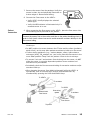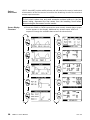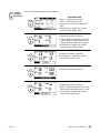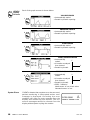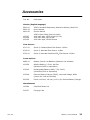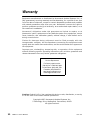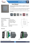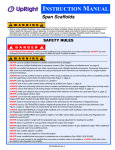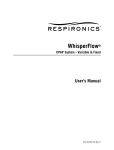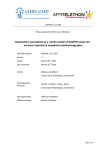
1
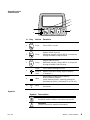
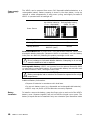
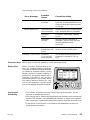
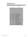
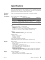
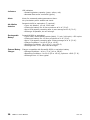
HANDHELD RESPIRATORY MECHANICS MONITOR User’s Manual VentCheck Model 101 October 30, 1997 Catalog No. 6800-23-02 Copyright ©1997. Novametrix Medical Systems Inc. 5 Technology Drive, Wallingford, Connecticut, U.S.A. 06492. All rights reserved. About this manual This manual is written for clinical personnel using the VENT✔ (VentCheck) Handheld Respiratory Mechanics Monitor, Model 101, and the flow sensors and accessories intended for use with the monitor. This document contains information which is proprietary and the property of Novametrix Medical Systems Inc., and may not be reproduced, stored in a retrieval system, translated, transcribed, or transmitted, in any form, or by any means, without the prior explicit written permission of Novametrix Medical Systems Inc. Novametrix reserves the right to change specifications without notice. VentCheck and the VENT✔ logo are trademarks of Novametrix Medical Systems Inc. VENT✔ Technical Description Per requirements of IEC 601-1, VENT✔ is classified as class II equipment, internally powered, with type BF applied part, and an enclosure protection rating of IPX1. Transport/Storage: -10 to +55° C (14-131° F), 10-95% R.H. non-condensing Operating Conditions: +10 to +40° C (50-104° F), 10-90% R.H. non-condensing The VENT✔ (VentCheck) Handheld Respiratory Mechanics Monitor, Model 101, contains no user serviceable parts. Refer servicing to qualified service personnel. (See Accessories on page 21 for listings of the Service Manual and Service Test kit for use by technical personnel.) Declaration of Conformity with European Union Directive The Authorized Representative for Novametrix equipment is: D.R.M. Green European Compliance Services Limited, Oakdene House, Oak Road, Watchfiled Swindon, Wilts SN6 8TD United Kingdom Manual Revision History 31-Jul-97 Release at Rev. 00. 17-Oct-97 Rev. 01. Including software release version 1.1. 30-Oct-97 Rev. 02. Including software release 1.2. 2 VENT✔ Users Manual Rev. 02 Table of Contents General Description . . . . . . . . . . . . . . . . . . . . . . . . . . . . . . . . . . . . . . . . . 5 Indications for Use . . . . . . . . . . . . . . . . . . . . . . . . . . . . . . . . . . . . . . . 5 Contra-indications . . . . . . . . . . . . . . . . . . . . . . . . . . . . . . . . . . . . . . . 5 Principles of Operation . . . . . . . . . . . . . . . . . . . . . . . . . . . . . . . . . . . . 5 Patient Safety . . . . . . . . . . . . . . . . . . . . . . . . . . . . . . . . . . . . . . . . . . 6 Warnings . . . . . . . . . . . . . . . . . . . . . . . . . . . . . . . . . . . . . . . . . . . . . . 6 Cautions . . . . . . . . . . . . . . . . . . . . . . . . . . . . . . . . . . . . . . . . . . . . . . 7 Notes . . . . . . . . . . . . . . . . . . . . . . . . . . . . . . . . . . . . . . . . . . . . . . . . 7 Preparation for Use . . . . . . . . . . . . . . . . . . . . . . . . . . . . . . . . . . . . . . . . . 8 Getting Acquainted . . . . . . . . . . . . . . . . . . . . . . . . . . . . . . . . . . . . . . . 8 Keypad Controls and Indicators . . . . . . . . . . . . . . . . . . . . . . . . . . . . . . 9 Symbols . . . . . . . . . . . . . . . . . . . . . . . . . . . . . . . . . . . . . . . . . . . . . . 9 Power supply options . . . . . . . . . . . . . . . . . . . . . . . . . . . . . . . . . . . . . 9 Battery Installation . . . . . . . . . . . . . . . . . . . . . . . . . . . . . . . . . . . . . . 10 External Battery Charger . . . . . . . . . . . . . . . . . . . . . . . . . . . . . . . . . . 11 Features Connector . . . . . . . . . . . . . . . . . . . . . . . . . . . . . . . . . . . . . 11 Monitor Operation . . . . . . . . . . . . . . . . . . . . . . . . . . . . . . . . . . . . . . . . . 12 Power On/Off . . . . . . . . . . . . . . . . . . . . . . . . . . . . . . . . . . . . . . . . . . 12 Flow Sensor . . . . . . . . . . . . . . . . . . . . . . . . . . . . . . . . . . . . . . . . . . . 12 Patient Connection . . . . . . . . . . . . . . . . . . . . . . . . . . . . . . . . . . . . . . 13 Patient Disconnect . . . . . . . . . . . . . . . . . . . . . . . . . . . . . . . . . . . . . . 14 Screen Display Flowchart . . . . . . . . . . . . . . . . . . . . . . . . . . . . . . . . . 14 DATA Display Screens . . . . . . . . . . . . . . . . . . . . . . . . . . . . . . . . . . . . 15 GRAPH Display Screens . . . . . . . . . . . . . . . . . . . . . . . . . . . . . . . . . . . 16 System Errors . . . . . . . . . . . . . . . . . . . . . . . . . . . . . . . . . . . . . . . . . 16 Parameter Alerts . . . . . . . . . . . . . . . . . . . . . . . . . . . . . . . . . . . . . . . 17 Battery Alert . . . . . . . . . . . . . . . . . . . . . . . . . . . . . . . . . . . . . . . . . . 17 Cleaning and Disinfecting . . . . . . . . . . . . . . . . . . . . . . . . . . . . . . . . . 17 Parameter List . . . . . . . . . . . . . . . . . . . . . . . . . . . . . . . . . . . . . . . . . . . 18 Specifications . . . . . . . . . . . . . . . . . . . . . . . . . . . . . . . . . . . . . . . . . . . . 19 Accessories . . . . . . . . . . . . . . . . . . . . . . . . . . . . . . . . . . . . . . . . . . . . . . 21 Warranty . . . . . . . . . . . . . . . . . . . . . . . . . . . . . . . . . . . . . . . . . . . . . . . 22 Rev. 02 VENT✔ Users Manual 3 4 VENT✔ Users Manual Rev. 02 General Description The VENT✔ (VentCheck) Handheld Respiratory Mechanics Monitor, Model 101, from Novametrix Medical Systems Inc., is an easy-to-operate stand-alone respiratory mechanics monitor. It is intended to be used in patient monitoring environments by technically skilled clinical personnel. Indications for Use VENT✔ is indicated for use by technically skilled clinical personnel as a mechanics monitor for mechanically ventilated or spontaneously breathing persons in monitoring environments including the intensive care unit (ICU), the operating room (OR) and in emergency/transport care. The device is intended for shortterm use (nominally 1 hour) and is NOT intended for continuous monitoring. VENT✔ compatible flow sensors are a single patient use devices having fittings that comply with ISO 5356-1 and may be used in conjunction with endotracheal tubes, face masks, and breathing circuit devices that also comply with the specification. Pediatric/adult flow sensors are indicated for use with endotracheal tubes with internal diameters of ≥6 mm. Neonatal flow sensors are indicated for use with endotracheal tubes with internal diameters of ≤4 mm. Further, for endotracheal tubes with internal diameters of 4.5 to 5.5 mm, in general, neonatal sensors are indicated if the patient weight <10 kg or tidal volume <100 ml, and pediatric/ adult sensors are indicated where patient weight ≥10 kg and tidal volume ≥100 ml. Contraindications VENT✔ is intended for short-term use (nominally 1 hour) and is NOT intended as a continuous monitoring device. VENT✔ does NOT compensate for the presence of high oxygen concentrations, anesthetic gases or helium-oxygen mixtures. When such mixtures are present, errors in flow measurements may exist. Principles of Operation VENT✔ measures the respiratory parameters of flow and pressure. Many other parameters are calculated from the flow and pressure signals, including: volume (tidal and minute), airway resistance, and lung compliance. VENT✔ uses fixedorifice, differential pressure pneumotachs. The pneumotach is the airway flow sensor that converts volumetric flow rate into a differential pressure signal. Gas flowing through the flow sensor causes a small pressure drop across the two ports connected to the sensor. This pressure drop is transmitted through the tubing to the monitor where differential and absolute pressure transducers are located. This pressure drop is correlated to flow according to the factory stored calibration. (The relationship between the volumetric flow-rate and the resulting differential pressure is governed by standard fluid mechanics equations.) User calibration is not required because of the ability of the plastic injection mold to produce precision flow sensors. Empirical calibration for the specific pneumotach type (pediatric/adult, neonatal, etc.) is performed at the factory and is stored in the monitor. The pressure transducer is automatically "zeroed" to correct for changes in ambient temperature, electronics and position (gravity effects). Rev. 02 VENT✔ Users Manual 5 Patient Safety Keep the VENT✔ and its accessories clean. Do not operate the VENT✔ when it is wet due to spills or condensation. Connect only Novametrix Series 3 Flow Sensors to the VENT✔. For maximum performance; keep the pressure sensor ports oriented upward, and keep the sensor clear of moisture and secretions by proper breathing circuit maintenance. Connect the sensor first to the VENT✔ and then to the patient breathing circuit in order to limit circuit volume loss and to avoid excessive moisture build-up in the flow sensor tubing. VENT✔ has electrically isolated inputs. Patient leakage current flowing from the instrument to ground is limited to less than 50 µA at 120 V, 60 Hz. Patient isolation is greater than 10 MΩ, 2500 V rms at 60 Hz. Where electromagnetic devices (i.e., electrocautery) are used, patient monitoring may be interrupted due to electromagnetic interference. Electromagnetic fields up to 3 V/m will not adversely affect system performance. VENT✔ contains no user serviceable parts. Refer servicing to qualified service personnel. (See Accessories on page 21 for listings of the Service Manual and Service Test kit for use by technical personnel.) This product and its accessories which have patient contact are latex free. Warnings ! WARNING: Indicates a potentially harmful condition that can lead to personal injury. Explosion Hazard: Do NOT use the VENT✔ in the presence of flammable anesthetics. Use of this instrument in such an environment may present an explosion hazard. Electrical Shock Hazard: Always turn the monitor off before cleaning it. Do NOT use a damaged monitor or sensor. Refer servicing to qualified service personnel. Fire Hazard: The VENT✔ should not be exposed to elevated oxygen levels at elevated pressures. Use in such an environment may present a fire hazard. Failure of Operation: If the monitor fails to respond as described, do not use it until the situation has been corrected by qualified personnel. Do not apply tension to the sensor tubing while connected to a patient breathing circuit, as accidental extubation may result. Do not position the flow sensors tubing in any manner that may cause entanglement or strangulation. Use the optional external battery charger in non-patient areas only. 6 VENT✔ Users Manual Rev. 02 Cautions ! CAUTION: Indicates a condition that may lead to equipment damage or malfunction. Federal (U.S.A.) law restricts this device to sale, distribution, or use by or on the order of a licensed medical practitioner. Electrical Shock Hazard: Always turn the monitor off before cleaning. Do NOT use a damaged monitor. Do NOT use a damaged flow sensor. Do NOT immerse the monitor or sensors in liquids. Do NOT sterilize the monitor or the sensors. No user serviceable parts inside. Refer servicing to qualified service personnel. Operate at temperatures between +10° C to +40° C (50-104° F), < 90% relative humidity (non-condensing). Avoid storing the monitor at temperatures less than -20° C or greater than +55° C (<-4° F or >131° F). Notes NOTE Indicates points of particular interest or emphasis and intended to provide for more efficient or convenient operation. The VENT✔ operates with Novametrix Series 3 Flow Sensors only. The VENT✔ performs an automatic zero (self calibration) periodically and as needed. During this time, monitoring is interrupted for less than three seconds. The automatic zero can be manually initiated by simultaneously pressing the DATA and GRAPH keys. After changing the sensor from Adult to Neonatal (while the VENT✔ is operational), wait 30 seconds then perform an automatic zero. This product and its accessories which have patient contact are free of latex. The C20/C Compliance Ratio (neonatal) parameter is not supported. To determine the VENT✔ software version, turn the monitor on. During the self test performed at power up, the software level is shown on the third line as main-101-xx, where xx is the software version. Some VENT✔ monitors were produced with the statement Use only Novametrix approved devices, 13 VDC, 1A located on the label at the Flow Sensor Input Connector. This erroneous statement does NOT apply to the VENT✔ monitor and should be ignored. Rev. 02 VENT✔ Users Manual 7 Preparation for Use Getting Acquainted The VENT✔ Handheld Respiratory Mechanics Monitor, Model 101 is shown below. Front View Keypad & Display Top View Connect Series 3 Flow Sensor Flow Sensors Ve To Neonatal Sensor #6718/6720 ti Pa o T or l at i t n en t Pediatric/Adult Sensor #6717 Side/Bottom View Features Connector Quick Guide 8 VENT✔ Users Manual Battery Access Compartment Rev. 02 Keypad Controls and Indicators 1 2 3 4 POWER GRAPH DATA NEO B A # Key Action Function 1 POWER Press Turns VENT✔ on/off. 2 GRAPH Press Display Graph Screens. Additional presses causes VENT✔ to sequence through available Graph Screens. 3 DATA Press Display Data Screens. Additional presses causes VENT✔ to sequence through available Data Screens. Press Turns display backlight on/off. Press & Hold Adjusts contrast/viewing angle of display (1 step/sec.) None Illuminated if powered from battery Green; battery charged Yellow flashing slowly; capacity getting low Red flashing quickly; exhausted in 10-15 min. None Illuminates when a Neonatal sensor is connected. 4 A B NEO Symbols Symbol Description Patient Isolation Identifies patient isolation connection as type BF. ! Rev. 02 Attention Consult manual for detailed information. VENT✔ Users Manual 9 Power supply options The VENT✔ can be powered from seven AA disposable alkaline batteries, or a rechargeable battery. Battery capacity is shown in the chart below; it may be reduced in colder temperatures or with power cycling, and slightly increased if VENT✔ is operated with its backlight off. Standard AA alkaline batteries (7 ea. - disposable) Optional Rechargeable battery, (NiMH 7.2 vdc) 8 hours 12 hours n/a 1.5 hours 400038 (battery) 6862-00 (case) 400043 Power Source Capacity, continuous Recharge Time Catalog Number AA Alkaline Batteries. To power VENT✔ from AA alkaline batteries, insert seven disposable alkaline batteries (Panasonic AM3X or equivalent) into the Battery Case (Cat. No. 6862-00) following the polarity markings on the case. ! WARNING: Do not recharge or incinerate alkaline batteries. Attempting to do so may cause the batteries to leak or explode. Rechargeable Battery. VENT✔ can operate from the optional Duracell® DR30 (or equivalent) rechargeable battery. If a rechargeable battery has not been used for three months or more, recharge it before use. ! WARNING: Battery can explode, leak or catch on fire if heated or exposed to fire or high temperatures. Additional Battery Information. Dispose of batteries in accordance with local laws. Do not mix battery types (e.g. disposable and rechargeable AA batteries). VENT✔ may not power up if the batteries are nearly depleted. Battery Installation 10 To install or remove the battery, grasp the finger grips on each end of the VENT✔ battery cover. Squeeze together and pull so that the hinged cover opens. The battery is keyed and can be installed in only one orientation (see illustration inside VENT✔ Users Manual Rev. 02 battery compartment). The contacts should go in first and be located toward the top left of the monitor. Close the battery cover before operating the monitor. Connect only Novametrix approved devices Hinged Battery Compartment Cover Swing battery cover open Finger Grips External Battery Charger An optional external charger for the Duracell® DR30 is available. The external charger allows the battery to be recharged outside of the VENT✔ monitor. The external charger is for use with the rechargeable Duracell DR-30 battery only. In a non-patient area, connect the external charger to an AC source. Remove the battery from the VENT✔ and insert it into the external charger. The battery will be fully charged in approximately 1 1/2 hours. Refer to the instructions supplied with the charger for additional information. ! Features Connector Rev. 02 WARNING: The external battery charger should NOT be operated near or in close proximity to patients and/or other medical equipment in operation. The VENT✔ features connector is for use only with future optional Novametrix accessories. The connector meets the patient safety requirements set forth by the safety agencies as labelled on the VENT✔ monitor. VENT✔ Users Manual 11 Monitor Operation Prior to operating the VENT✔ monitor, please note the following; VENT✔ is intended for short-term use (nominally 1 hour) and is NOT intended as a continuous monitoring device. VENT✔ does NOT compensate for the presence of high oxygen concentrations, anesthetic gases or helium-oxygen mixtures. When such mixtures are present, errors in flow measurements may exist. The VENT✔ performs an automatic zero (self calibration) periodically and as needed. During this time, monitoring is interrupted for less than three seconds. The instructions below assume the VENT✔ has a charged battery installed and that no flow sensor is connected. Use of equipment other than mentioned here may yield different results. Power On/Off 1. Press the POWER key to turn VENT✔ on (or off). 2. Verify both the NEO and battery indicators illuminate as part of the self-test performed at power up. 3. Press and hold the LAMP key to adjust the contrast/viewing angle of the display. 4. If desired, press the LAMP key to turn the display backlight on/off. POWER GRAPH DATA NEO 5. Verify INSERT FLOW SENSOR message appears. Flow Sensor 6. Select a Series 3 Flow Sensor based on the patient type. #6717, Pediatric/Adult sensor adds approximately 6.5 cc of deadspace. #6718/6720, Neonatal sensors add approximately 0.8 cc of deadspace. ET Tube Size ≥6 mm 4.5 to 5.5 mm ≤4 mm 12 VENT✔ Users Manual Series 3 Flow Sensor Pediatric/Adult Pediatric/Adult if weight ≥10 kg and VT ≥100 ml Neonatal if weight <10 kg or VT <100 ml Neonatal Neonatal Sensor #6718/6720 Pediatric/Adult Sensor #6717 n ti e a P To tor la n ti e V To t Rev. 02 7. Remove the sensor from the package. Verify the sensor is clean, dry and physically intact with no broken edges or disconnected tubing. 8. Connect the Flow sensor to the VENT✔. Verify VENT✔ briefly displays the selected sensor type. Verify the NEO indicator is illuminated only if a neonatal sensor is in use. Patient Connection 9. After connecting the flow sensor to the VENT✔, place the flow sensor into the breathing circuit proximal to the patient. NOTE Connect the sensor first to the monitor and then to the patient breathing circuit in order to limit circuit volume loss and to avoid excessive moisture build-up in the flow sensor tubing. The sensor is best placed between the endotracheal tube and the ventilator circuit wye. Do NOT position the sensor between the ET tube and the elbow (pediatric/ adult circuit), as this may allow patient secretions to build up in the sensor. If other airway appliances (e.g., suction adapter, elbow, heat moisture exchanger (HME), CO2 adapter, etc.) are in use, place the flow sensor in the more distal positionaway from the patientcloser to the circuit wye. To prevent rain-out and moisture from draining into the sensor, do NOT place the sensor in a gravity dependent position where moisture and secretions may accumulate. Periodically check the flow sensor and tubing for excessive moisture and/or secretion build-up. After changing the sensor from Adult to Neonatal (while the VENT✔ is operational), wait 30 seconds then perform an automatic zero by simultaneously pressing the DATA and GRAPH keys. To VENT✔ To ventilator Point tubing upward To VENT✔ Pediatric/Adult Flow Sensor Point tubing upward To ventilator Neonatal Flow Sensor To patient Rev. 02 To patient VENT✔ Users Manual 13 Patient Disconnect VENT✔ does NOT provide audible alarms and will not alert the user to inadvertent disconnection of the flow sensor from either the breathing circuit of the monitors sensor input connector. NOTE To limit circuit volume loss and avoid excessive moisture build-up in the flow sensor tubing, disconnect the flow sensor from the breathing circuit before disconnecting the flow sensor from the monitor. Screen Display Flowchart 10. Press the GRAPH or DATA keys and the most recently viewed data or graph screen appears in the display. Additional key presses cause VENT✔ to sequence through the available data screens as shown below. 1 1 GRAPH 2 DATA 2 GRAPH 3 DATA 3 GRAPH DATA 4 4 GRAPH 5 5 GRAPH 14 DATA VENT✔ Users Manual DATA Rev. 02 DATA DATA Display Screens Each of the data screens is shown below. VOLUME DATA 1 DATA Spon - spontaneous breath, Mech - mechanical breath. Values from rolling 8-breath average. Activity bar is breath-by-breath using Volume Graph scale. PRESSURE DATA Breath-by-breath reporting. 2 DATA If auto-PEEP is detected, the word auto appears under PEEP and the display reflects total PEEP present. Activity bar is breath-by-breath using Pressure Graph scale. TIMING DATA Breath-by-breath reporting. 3 DATA Activity bar is breath-by-breath using Flow Graph scale. FLOW/VOLUME DATA Breath-by-breath reporting. 4 DATA MECHANICS DATA Breath-by-breath reporting. 5 DATA RSBI - Pediatric/Adult sensor in use, blank when Neonatal sensor in use. Activity bar is breath-by-breath using Flow Graph scale. Rev. 02 VENT✔ Users Manual 15 GRAPH GRAPH Display Screens Each of the graph screens is shown below. VOLUME GRAPH Automatically scaled. 1 GRAPH Breath-by-breath reporting. PRESSURE GRAPH Automatically scaled. 2 GRAPH Breath-by-breath reporting. FLOW GRAPH Automatically scaled. 3 GRAPH Breath-by-breath reporting. GRAPH Automatically scaled. FLOW/VOLUME GRAPH 4 F 4 breaths overlayed then cleared. V Breath-by-breath. PRESSURE/VOLUME GRAPH 5 GRAPH Automatically scaled. V 4 breaths overlayed then cleared. P Breath-by-breath. RSBI - Pediatric/ Adult sensor in use, blank when Neonatal sensor in use. System Errors 16 If VENT✔ detects that a system error has occurred, patient monitoring is interrupted and an error me ssage is d isp layed. Cor recting t he e rror condition will clear the error message from the display and monitoring will resume. The CALL SERVICE messages cannot be cleared from the display without power cycling the monitor. VENT✔ Users Manual Rev. 02 The following errors are possible; Error Message CALL SERVICE INVALID SENSOR TYPE FLOW OUT OF RANGE PRESSURE > 120 CM H2O Possible Cause Corrective Action Faulty monitor or sensor. Remove monitor and flow sensor from use. Contact qualified service personnel and note number shown in triangle. Incorrect sensor type connected. Replace sensor with a valid sensor type, pediatric/adult or neonatal. Damaged sensor. Connector is damaged. Replace sensor. Damaged monitor. Monitors sensor connector is damaged. Remove from use and contact qualified service personnel. Flow rate greater than 180 L/min. VENT✔ does not operate with flow rates in excess of 180 L/min. Pressures >120 cm H2O were detected. Do not expose monitor/sensor to pressures in excess of 120 cm H2O. Parameter Alerts VENT✔ does not provide audible or visible parameter alerts. Battery Alert VENT✔ monitors, and indicates to the user, the remaining battery capacity. The battery indicator illuminates GREEN to indicate a charged battery, slowly flashes YELLOW to indicate capacity is getting low, and quickly flashes RED to i n d ic a t e t h e b a t t e r y w i l l b e c o m e exhausted within 10-15 minutes. When the battery indicator flashes RED, VERY LOW BATTERY appears in the title stripe area of the display (example at right). Cleaning and Disinfecting POWER GRAPH DATA NEO Turn VENT✔ off before cleaning. Do not immerse the monitor. Do not attempt to sterilize the monitor. The monitor can be cleaned and disinfected with solutions such as isopropyl alcohol 70% solution, 2% glutaraldehyde solution, or bleach 10% solution, then wiped with a clean water dampened cloth to rinse and dry before use. Treat Series 3 Flow Sensor in accordance with established protocol for single-patient use items. Rev. 02 VENT✔ Users Manual 17 Parameter List Parameters reported by the VENT✔ are summarized below. Abv. Units Cdyn ml/cmH2O I:E 18 VENT✔ Users Manual Parameter Dynamic Compliance Inspiratory:Expiratory Ratio MAP cmH2O MV Liters NIP cmH2O Negative Inspiratory Pressure PEEP cmH2O Positive End Expiratory Pressure PEF LPM (L/min) Peak Expiratory Flow PIF LPM (L/min) Peak Inspiratory Flow PIP cmH2O Peak Inspiratory Pressure Plat cmH2O Plateau Pressure Raw cmH2O/L/sec RR br/min RSBI br/min/L Te sec Expiratory Time Ti sec Inspiratory Time VT ml Tidal Volume (Averaged) VTi ml Tidal Volume Inspiratory VTe ml Tidal Volume Expiratory Mean Airway Pressure Minute Volume Airway Resistance Respiratory Rate Rapid Shallow Breathing Index Rev. 02 Specifications Below are specifications for the Novametrix VENT✔ Handheld Respiratory Mechanics Monitor, Model 101. These specifications are listed for informational purposes only, and are subject to change without notice. Principle of Operation Fixed orifice differential pressure pneumotach. No calibration required. Flow Sensors Series 3 Flow Sensors, Single Patient Use ET Tube Size ≥6 mm 4.5-5.5 mm ≤4 mm Series 3 Flow Sensor Catalog No. Pediatric/Adult 6717 Pediatric/Adult if weight ≥10 kg and VT ≥100 ml Neonatal if weight <10 kg or VT <100 ml 6717 6718/6720 Neonatal 6718/6720 Flow: Range: Adult Sensor: ± 2 to 180 L/min. Range: Neonatal Sensor: ± 0.25 to 35 L/min. Accuracy: Greater of ± 0.5 L/min or 5% of reading (pediatric/adult sensor). Greater of ± 0.125 L/min or 5% of reading (neonatal sensor). Pressure: Range: −120 to 120 cmH2O Accuracy: Greater of ± 0.5 cmH2O or 2% of reading. Respiratory Rate Range: 0 to 120 br/min Accuracy: ±1 br/min Resolution: 1 br/min Sensor Type Identification: Automatic. Automatic Barometric Pressure Compensation: 400-800 mmHg. Physical VENT✔ monitor Size (maximum height, width, depth): 20 × 9.5 × 4.8 cm (8 × 3.75 × 1.875 in.). Weight (typical): without battery: 370 grams, (13 oz.), with alkaline battery pack: 595 grams (21 oz.), with rechargeable battery: 710 grams (25 oz.). Operating Environment: +10 to +40° C (50-104° F), 10 to 90% relative humidity non-condensing. Transport/Storage Environment: -10 to +55° C (14-131° F), 10 to 95% relative humidity non-condensing. Display Liquid Crystal Display 128 × 64 pixels, 2.5 × 1.25 inches. Adjustable contrast with backlight and plastic shield. Rev. 02 VENT✔ Users Manual 19 Indicators LED indicators Remaining battery capacity (green, yellow, red). Neonatal flow sensor connected (green). Alerts Alerts for measured patient parameters: None. Very low battery alert: audible and visual. AA Alkaline batteries Panasonic AM3X or equivalent, (7 required). Type: AA, Alkaline, 1.5 vdc, 1500 mAH. Continuous battery life: 8 hours minimum at 21 °C (70 °F). Up to 85% capacity remaining after 4 years storage at 21 °C (70 °F). Recharge: Disposable, do not recharge. Rechargeable Battery: Duracell® DR30 or equivalent Type: DR30, Nickel-Metal-Hydride (NiMH), 7.2 vdc, 2400 mAH, >250 cycles. Continuous battery life: 12 hours minimum at 21 °C (70 °F). Up to 70% capacity remaining after 30 days storage at 21 °C (70 °F). Charge Conditions: 0 to 45 °C (32 to 113 °F). Discharge Conditions: -20 to 50 °C (-4 to 122 °F). Recharge time: 1.5 hr with external charger. External Battery Charger: Charger compatible with Duracell® DR30 or equivalent battery Storage Conditions: -40 to +70 °C (-40 to 158 °F). Operating Conditions: 0 to 50 °C (32 to 122 °F); optimum +25°C (77 °F). Recharge time: 1.5 hour typical 20 VENT✔ Users Manual Rev. 02 Accessories Cat. No. Description Monitor (English language) 6800-00 6800-23 6800-90 VENT✔ Handheld Respiratory Mechanics Monitor, Model 101 User's Manual Service Manual 420037 420038 420039 VENT✔ Quick Guide Inservice Video VHS video tape, NTSC format (U.S.A.) VHS video tape, PAL format VHS video tape, SECAM format Flow Sensors 6717-00 Series 3, Pediatric/Adult Flow Sensor. 10/Box 6718-00 Series 3, Neonatal Flow Sensor. 10/Box 6720-00 Series 3, Neonatal Combined CO2/Flow Sensor. 10/Box Power Options 6862-00 Battery Case for AA Batteries (batteries not included) 400038 Alkaline Battery, 1.5 vdc, AA Size (Panasonic AM3X or equivalent) 400043 Rechargeable Battery, NiMH, 7.2V, 2.4AH, (Duracell® DR30 or equivalent) 400049 External Battery Charger (DR30), Universal Voltage, NiMH (power line cord not included) 600026 Power Line Cord, 120 vac, (U.S.A.) for External Battery Charger Miscellaneous Rev. 02 140084 Pole/Shelf Mount Kit 315107 Carrying Case VENT✔ Users Manual 21 Warranty Equipment manufactured or distributed by Novametrix Medical Systems Inc., is fully guaranteed, covering materials and workmanship, for a period of one year from the date of shipment, except for certain disposable products and products with stated guarantees other than one year. Novametrix reserves the right to perform guarantee service(s) at its factory, at an authorized repair station, or at the customers installation. Novametrix obligations under this guarantee are limited to repairs, or at Novametrix option, replacement of any defective parts of our equipment, except fuses, batteries, and calibration gasses, without charge, if said defects occur during normal service. Claims for damages during shipment must be filed promptly with the transportation company. All correspondence concerning the equipment must specify both the model name and number, and the serial number as it appears on the equipment. Improper use, mishandling, tampering with, or operation of the equipment without following specific operating instructions will void this guarantee and release Novametrix from any further guarantee obligations. Service Department For factory repair service: Call toll free: 1-800-243-3444 To Call Direct: (203) 265-7701 Facsimile (203) 284-0753 http://www.novametrix.com [email protected] Caution: Federal (U.S.A.) law restricts this device to sale, distribution, or use by or on the order of a licensed medical practitioner. Copyright 1997. Novametrix Medical Systems Inc., 5 Technology Drive, Wallingford, Connecticut, 06492. All rights reserved. 22 VENT✔ Users Manual Rev. 02