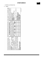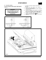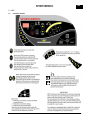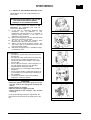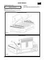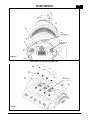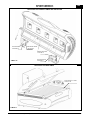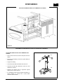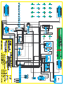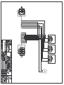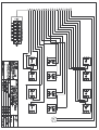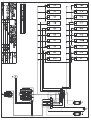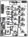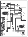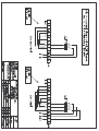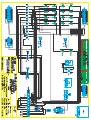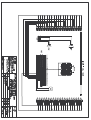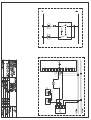
1
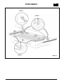
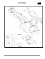
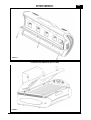
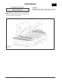
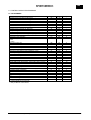
30020 GRUARO-ITALY - VIA DELL’INDUSTRIA 7
Tel. 0421/767676 Fax 0421/767670
INSTALLATION, USE AND MAINTENANCE MANUAL
USA
Cod.man.:11284.410.2.0 (01/06/06)
Cod.app.:10297.069.0.0 (230V 3~ 60Hz)
USA
INDEX
INDEX OF SECTIONS
1 - GENERAL INFORMATION
1.1
1.2
1.3
1.4
1.5
pag. 2
Labels
Introduction
4
General tanning instructions
4
5
Transport and handling
Preparation for installation by the client
5
2 - SAFETY INFORMATION
2.1 General
2.2 Noise
2.3 Regulations
6
6
6
3 - TECHNICAL DATA
3.1 Dimensions and technical data EXTASY
7
4 - INSTALLATION
4.1
4.2
4.3
4.4
Pre-installation
Connections
Assembly instructions
Voltage-change
7
7
8
11
5 - USE
5.1 Control board
12
13
5.2 Safety of the persons exposed to UV
5.3 Programming the pre-defined session times 14
6 - ORDINARY MAINTENANCE MADE BY THE
CUSTOMER
6.1 Ordinary maintenance
15
7 - EXTRAORDINARY MAINTENANCE MADE BY A
SKILLED TECHNICIAN
7.1 Extraordinary maintenance
7.2 Periodic control procedure
18
18
8 - CONTROL BOARD PROGRAMMING
8.1 Programming
23
9 - TROUBLESHOOTING AND RAPID DIAGNOSTICS
9.1 Troubleshooting and rapid diagnostics
27
10 - DEMOLITION AND WASTE MATERIALS
10.1 Waste materials
10.2 Demolition of the machine
27
27
11 – REPLACEMENTS AND CIRCUIT DIAGRAMS
11.1 Spare parts list
11.2 Circuit diagrams legend
28
29
12 - MEDICATION
12.1 Medication
30
13 - WARRANTY
13.1 Limited warranty
30
Cod. man.11284.410.2.0 (01/06/06)
1/30
USA
1 - GENERAL INFORMATION
1.1 LABELS
Cod. man.11284.410.2.0 (01/06/06)
2/30
USA
1 - GENERAL INFORMATION
Cod. man.11284.410.2.0 (01/06/06)
3/30
USA
1.2 INTRODUCTION
Skin type II.
This is the individual that usually burns easily and
severely. Tans minimally or lightly and peels.
Skin type III.
Often referred to as “average” complexion burns
moderately and tans about average.
Skin type IV.
This individual burns minimally, tans easily and above
average.
Skin type V.
This individual’s system rarely burns, tans easily and
substantially.
Session times are calculated for a supply voltage of
208V.
This product is in conformity with performance
standards for sunlamp products under No.21 CFR
1040.20.
IMPORTANT
BEFORE OPERATING THE MACHINE, READ
THE INSTRUCTIONS CONTAINED IN THIS
OPERATING MANUAL CAREFULLY AND
COMPLETELY.
KEEP THIS MANUAL AND ALL ENCLOSURES
IN AN ACCESSIBLE PLACE WHERE IT CAN BE
REFERRED TO BY ALL USERS (OPERATORS,
MAINTENANCE PERSONNEL AND THOSE
CLIENTS
WHO
ASK
FOR
DETAILED
INFORMATION).
This Technical Manual is designed for use by installers
and operators, and should be read carefully and
completely before the machine is operated. The manual
should always be available for reference and should be
kept in a safe place so that it stays in good condition for
future reference. For further copies or updates of the
manual, contact the manufacturer at the address on the
front page.
Sportarredo SpA reserves the right to make changes to
the product and to the manual without being obliged to
update the preceding manuals.
This manual contains all the instructions and
information necessary to operate the machine:
• Correct installation of the machine.
• Description of the functions of the machine.
• Circuit diagrams.
The installers and the operators can use this manual to
understand the characteristics of the machine and to
learn the correct operating procedure.
RECOMMENDED EXPOSURE SCHEDULE
First three sessions should be at 48 hour intervals. Followed by the
gradual increasing of exposure times until maximum tanning has
occurred (in approximately 4 weeks). MAXIMUM EXPOSURE is 15
minutes.
Week 1
1st-3rd
Session
Week 2
4rd-6rd
Session
Week 3
7rd-9rd
Session
Subsequent
Weekly
Session
II
III
IV
V
3 min.
3 min.
3 min.
3 min.
7 min.
7 min.
8 min.
8 min.
10 min.
10 min.
11 min.
12 min.
12 min.
13 min.
14 min.
15 min.
This schedule is intended to be used with the following
lamps: (standard configuration)
Kalfasun B17-S RAPID 160W
Kalfasun 630F
Kalfasun 1530F
1.3 GENERAL TANNING INSTRUCTIONS
DANGER! Ultraviolet Radiation.
Follow instructions. Avoid overexposure. As with natural
sunlight, overexposure can cause eye and skin injury
and allergic reactions. Repeated exposure may cause
premature ageing of the skin and skin cancer.
WEAR PROTECTIVE EYEWEAR; FAILURE TO MAY
RESULT IN SEVERE BURNS OR LONG-TERM
INJURY TO THE EYES.
Medications or Cosmetics may increase your
sensitivity to the ultraviolet radiation. Consult physician
before using sunbed if you are using medications or
have a history of skin problems or believe yourself
especially sensitive to sunlight. If you do not tan in the
sun, you are unlikely to tan from the use of this product.
This device is intended to be used by only one person
at a time. Lie on the bed and lower the canopy down to
the stopping point.
CAUTION: EXPOSURE POSITIONS OTHER THAN
SPECIFIED MAY RESULT IN OVEREXPOSURE AND
ARE NOT RECOMMENDED.
Tanning normally begins after one to two exposures
and maximizes after one to four ( 1-4 ) weeks of
exposure following the recommended schedule for your
skin type.
Cod. man.11284.410.2.0 (01/06/06)
Skin
type
Blue cobalt filter and clear Superlux TR-T filter
(together).
REFLECTOR
LAMP
CLEAR SUPERLUX TR-T FILTER
BLUE COBALT FILTER
4/30
USA
1.4 TRANSPORT AND HANDLING
The machine is carefully protected and loaded onto
pallets before shipping. The various parts of the
machine must never be transported or stored in
positions which differ from the positions in which they
are shipped. In this case, the warranty shall be null and
void.
The machine must be handled with care in order to
prevent the risk of damage to the packaged sections.
All handling operations should be carried out by
authorised and trained personnel. When the machine is
delivered, immediately check that the packaging
material is whole and that no damage has occurred
during transport.
Any damage to the machine must be notified to the
carrier not later than eight calendar days from the date
of delivery. If internal damage is suspected, it is
advisable to accept the machine reserving the right to
check accordingly.
THE BREAKER MUST BE INSTALLED IN THE
POWER SUPPLY BOARD OF THE ESTHETICAL
CENTRE AND IT MUST BE DONE BY THE CENTRE
ITSELF.
Mod. EXTASY:
3x50A-30mA to feed 230V - 3phase 60Hz
The installation must be done by technical
personnel.
THE POWER SUPPLY CONNECTION (UNITBOARD) MUST BE DONE BY THE CENTRE. THE
SKILLED TECHNICIAN MUST USE A CERTIFIED
CABLE WITH THE PROPER SECTION AND WITH
ADEQUATE MECHANICAL PROTECTION, IN
ACCORDANCE WITH THE RULES IN FORCE.
SEE CAHAPTER 3.1 TABLES FOR TECHNICAL
DATA “POWER SUPPLY CABLE SECTION”
PLEASE CONTACT THE CUSTOMER SERVICE AT
PHONE NUMBER
1-866-899-4826 FOR ANY FURTHER DOUBT
THE CARRIER IS RESPONSIBLE FOR ANY
DAMAGE OCCURRING DURING TRANSPORT OF
THE MACHINE. SPORTARREDO WILL MAKE
EVERY EFFORT TO ASSIST THE CLIENT IN SUCH
CASES
Before the evening closing, or the closing for a
prolonged period you should operate on the
breaker in order to disconnect the power supply.
ALL MAINTENANCE OF THE MACHINE MUST
BE PERFORMED BY SPECIALIZED
TECHNICIANS FROM SPORTARREDO OR BY
PERSONS AUTHORIZED BY SPORTARREDO
USA INC.
TO HAVE A CORRECT USE OF THE
EQUIPMENT, THE ROOM TEMPERATURE MUST
NOT EXCEED THE 86°F DEGREES. IF ROOM
TEMPERATURE EXCEEDS THIS VALUE, WE
SUGGEST TO UTILIZE AN AIR-CONDITIONING
UNIT.
IMPORTANT !
ALWAYS DISCONNECT THE MACHINE
FROM THE POWER SUPPLY BY
PRESSING THE SWITCH BREAKER
BEFORE CARRYING OUT
MAINTENANCE
1.5 PREPARATION FOR INSTALLATION BY THE
CLIENT
Unless otherwise expressly specified in the contract, the
following must be provided by the client:
•
Connections to the electrical circuit, including the
protective wire generally referred to as the "EARTH
CONNECTION", unit feeding cable, power plug
and circuit breaker.
•
Canalization system for the emission of hot air.
•
External air intake.
•
All tools and equipment necessary for installation.
THE UNIT IS SUPPLIED FOR INPUT VOLTAGE AT
230V 3phase 60 Hz
AND IT IS SUPPLIED WITH THE FEEDING CABLE
To make a power cable connection or voltagechange,
make
reference
to
the
chapter
“INSTALLATION" paragraph “ VOLTAGE-CHANGE ”
and to the EXTASY n° 1/10 electrical diagram.
These operation must be done by technical
personnel.
Cod. man.11284.410.2.0 (01/06/06)
5/30
USA
2 - SAFETY INFORMATION
2.2
NOISE
The machine is designed and built in such a way as to
reduce operational noise as follows:
2.1 GENERAL
The employer must ensure that the persons assigned to the
operation of the machine receive adequate training
concerning possible accident risks, the devices fitted for
the safety of the operator and the client, the risks
associated with the emission of UV light and the general
accident-prevention
regulations
specified
by
international norms and local legislation.
Those responsible for operation, maintenance, cleaning
and control of the machine must adhere strictly to
the accident-prevention regulations applicable in the
country in which the machine is installed.
Before operating the machine, the operator must be
completely familiar with the position and the function
of all the controls and with the characteristics of the
machine. The operator must read this manual
carefully and completely.
The machine must be operated by fully-qualified
operators only.
Removal of the safety devices and protective barriers
is strictly forbidden.
No heavy weights must be placed on the moving parts
of the machine. The ventilation ducts and intake
grilles must not be obstructed by foreign bodies.
The machine must always be switched off and
disconnected from the power supply before
performing any routine or special maintenance
operations.
Unauthorised replacement of or repairs to any part or
section of the machine, or the use of accessories or
material that are not original or recommended by the
manufacturer, may represent a risk of injury, and
exonerate the manufacturer from all civil or penal
liability.
It is forbidden to stay near the appliance while it is
operating without eye protection.
•
•
The figures shown above have been determined
according to ISO 3746.
1
2
1m
1m
1m
1m
C
B
1m
A
1m
1m
1m
3
FRONT SIDE
4
2.3 REGULATIONS
Standards for safety of Luminaires-2000, UL 1598, &
CSA C22.2 No.250.0-00, Standard for Portable
Sun/Heat Lamps, ANSI/UL 428 & Standard for
Radiant Heaters and Ultraviolet Lamp Assemblies
for Cosmetics or Hygienic Purposes in Nonmedical
Applications, CAN/CSA C22.2 No. 224-M89.
In the planning of this unit the following rules and
provisions of the European Community have been
taken in consideration:
ECC Directive N. 91/368 dated 20.06.91, N.93/44
dated 14.06.1993, N.93/68 dated 22.07.
ECC Directive N.73/23 dated 19.02.73 known as “low
voltage directive”.
ECC Directive N.89/336 dated 03.05.1989 known as
“Electronic compatibility directive”.
En 60335-2-27 II part Special standard for units for the
treatment of the skin with ultraviolet and infrared
rays for home use and similar use.
"DANGEROUS ZONES": any zone internal to or in the
vicinity of the machine in which the presence of an
exposed person constitutes a risk for the safety and the
health of that person.
"EXPOSED PERSON": any person who is wholly or
partly in a dangerous zone.
"OPERATOR": person or persons assigned to the
installation, operation, adjustment, maintenance,
cleaning, repair and transport of the machine.
Cod. man.11284.410.2.0 (01/06/06)
Effective normalized sound power during operation,
see diagram below:
1 = 62 dB (A) max 2 = 60 dB (A) max 3 = 62 dB (A)
max 4 = 60 dB (A) max
Effective sound pressure with simulation of the actual
position of the person being treated:
A = 69 dB (A) max,
B = 70 dB (A) max,
C = 70 dB (A) max.
6/30
USA
3 - TECHNICAL DATA
4 - INSTALLATION
3.1 DIMENSIONS AND TECHNICAL DATA EXTASY
4.1 PRE-INSTALLATION
FIXED DUCT FOR HOT AIR
EXHAUST
MAXIMUM LENGTH
237 cm
93" in
MAXIMUM WIDTH
142 cm
55" in
MAXIMUM HEIGHT
176 cm
69" in
WEIGHT
640 Kg
1411 lb
EXTASY
U.M
POWER SUPPLY
V
DATA
230V 3ph
KW
14,9
NOMINAL CURRENT
A
38,5
FREQUENCY
Hz
60
WIRE SIZES
AWG
NOMINAL POWER
NUMBER OF WIRE
REQUIRED
EXHAUST AIR FLOW
4.2 CONNECTION
7
4
m³/h
2550
Pa
0÷200
HEAT PRODUCED
Kcal/h
12800
HEAT EXPELLED
Kcal/h
7680
EXAUST FAN PRESSURE
In order to ensure correct operation of the machine, it
should be installed in an area which has been prepared
as shown in the figure.
The connection of the exhaust air pipe must have on
the first part (50-60 cm / 19"-23" inch from the edge of
the fan) the minimum curving. This device has to be
done to reduce the noise of the fan caused by the
resistance of the hair, to improve the cooling of the
lamps and to have a better air flow during the tanning
session.
N.
3xKALFASUN 1530F
CANOPY LAMPS
N.
12xKALFASUN 630F
BED LAMPS
N.
20xKALFASUN
B17-S Rapid 160W
FACIAL LAMPS
UV EMISSION
SEE RAY EMISSION CERTIFICATE
Cod. man.11284.410.2.0 (01/06/06)
7/30
The area in which the machine is installed must be
adequately ventilated, fit the area with an air
intake from outside if necessary. To improve the
technical comfort we suggest to connect the tube to
expel the hot air to a fixed duct to expel the air
outward
• The metal structure of the machine is earthed by
means of insulated wires connected to the earth
terminal in the electrical junction box.
• The earth circuit must be in full compliance in
accordance with the rules in force.
• The earth connection must also be fitted to lowvoltage systems situated in wet or very damp areas
(if the voltage to earth is in excess of 25V for
alternating current or 50V for direct current).
• The earth wires connected to every part of the
various sections of the machine and the earth wires
from the various power circuits and user groups
must be connected to a single earthing circuit.
• Ensure that the materials used for the earth system
are suitably robust and provided with adequate
protection.
• The connection to the main earth terminal should be
as short as possible. The earth wires should not be
subjected to mechanical stress of any kind, and
must be protected against corrosion.
USA
4.3 ASSEMBLY INSTRUCTIONS
11 - Fit the connectors:
SEE ENCLOSED FIGURE 1A-1B
1-
2-
3-
4-
Match the acrylic-lamp group with the base E. Fix
it at the back with the two screws 4,8x13 as per
picture 1 and in front with the two screws 4,8x70
rising the acrylics as per picture 2. TABLE 1A.
•
•
•
•
Assemble the cover plastics E1, E2 and fix them
with two black cone-shaped screws 2,9x9,5. Apply
to the magnets the air filters of the lamps. TABLE
4 page 13.
•
•
•
Fit the lateral section F to the base E and bolt in
position using the 4 hexagonal-head M12x35
screws with 12x32 washer. TABLE 1B.
Screws the two pistons G (1) and fit them (2-3) on
the lateral part (see picture 4). TABLE 1B.
6-
Insert inside the base (keeping the position shown
in picture) the control box A, the ballast boxes B,C
and D. Pay extremely attention not to knock the
cooling fan of the lamps of the bed against the
feeder boxes. TABLE 1B. Fasten the pistons that
support the lamps bed group.
8-
•
Keeping the acrylic raised insert the brackets G1
following the right and left position. Fix the parts
firmly with the two screws flared 6x15 see
picture3. TABLE 1A.
5.-
7-
•
•
12 - Connect the power supply cable to the connector
inside the control box A.
13
Insert the two brackets which support the upper
section H into the pushing in the lateral section.
Ensure that the two limit-position bolt I face
upwards as shown in the FIGURE 1B.
Fix the head side fan M with three 3.9x13 large
head screws and the feet side fan N with four
M6x20 screws. Connecting the black connectors.
FIGURE 1B.
10
Assemble the cover plastic parts L1 with two
3.9x38 screws and 4x12 washer and the flared
screw placed on the top of the cover 3.9x13.
FIGURE 1B.
Cod. man.11284.410.2.0 (01/06/06)
When assembly of the unit is complete, connect
the negative pole of the battery-accumulator inside
the control box A for automatic raising of the
upper section.
WARNING!
Opening the base acrylic a finger switch cuts off the
power it restarts automatically closing down the acrylic.
Slide the upper section L onto the support
brackets as far as allowed by the two limit-position
bolts. Fix the upper section to the brackets using
the two 4,8x13 self-tapping screws. FIGURE 1B.
9
10-pin connector between ballast box D and
control box A;
16-pin connector between lateral and control
box A;
24-pin connector between ballast box C and
control box A;
10-pin connector between ballast box C and
control box A;
24-pin connector between head and control
box A;
3-pin black connector of the base decorative
light to the control box A;
10-pin connector between head and ballast
box D;
32-pin connector between bed and ballast
box C;
7-pin black connector between lateral and
bed (near the bed fan)
3-pin black connector of the head rest
decorative light E2 to the lateral.
In the control box there is a safety timer set this
timer at a value 10% longer than the maximum
session time.
e.g.: session time 15 min set the safety timer to 16,5
min.
8/30
USA
FIGURE 3
FIGURE 1
FIGURE 2
TABLE 1A
Cod. man.11284.410.2.0 (01/06/06)
9/30
USA
FIGURE 4
TABLE 1B
Cod. man.11284.410.2.0 (01/06/06)
10/30
USA
4.4 VOLTAGE CHANGE
•
To enter the terminal board for power supply, placed
inside the basement (control cassette), make reference
to Picture 1.
1)
2)
IMPORTANT !
3)
ALWAYS DISCONNECT THE MACHINE
FROM THE POWER SUPPLY BY
PRESSING THE SWITCH BREAKER
BEFORE CARRYING OUT
MAINTENANCE
4)
5)
TO MAKE VOLTAGE CHANGE FROM 230V 3~ TO
400 V 3N~
Remove the metal bridge upon terminals
(neutral connections) picture 1.
Change the feeding cable with a cable of adequate
section Ø 6 mm².
Change the breaker switch placed in the feeding
board of the esthetical centre system with one
having the following characteristics 4x32A-30mA.
Change the feeding plug with one having the
following characteristics 3P+N+ (32A).
Make the connections with wire Ø 6 mm² as shown
in picture 1.
Picture 1
TABLE 2
Cod. man.11284.410.2.0 (01/06/06)
11/30
USA
5 - USE
5.1
CONTROL BOARD
Cod. man.11284.410.2.0 (01/06/06)
12/30
USA
5.2 SAFETY OF THE PERSONS EXPOSED TO UV
Don’t use the unit in case of filter damages and
timer faults!
ATTENTION!
AN IMPROPER OR INCORRECT USE OF THE
UNIT CAN CAUSE SERIOUS BODILY
DAMAGES TO THE PERSON EXPOSED!
1)
2)
3)
4)
5)
From a careful analysis, as specified in EN
60335-2-27, the precautions that must be
observed are listed below.
If the client is undergoing treatment using
medication, such as antibiotics or antiinflammatory pharmaceuticals, it is advisable to
suspend tanning sessions.. In any case, it is
advisable to consult a doctor.
Before a tanning session, the skin should be clean
and free of cosmetics or perfumes.
Be sure not to exceed the exposure times
selected by the staff of the tanning centre.
Always use the special protective eyewear. The
eyes must under no circumstances remain open
during the tanning session.
After each tanning session, it is advisable to apply
a moisturising cream.
1
2
It’s advisable to:
•
Not exposure any part of the body more than one
time per day.
•
Not exposure to the unit and sun in the same day.
•
Do not expose yourself to the appliance if you
usually burn with normal sunlight or if you suffer
from sun-rash.
•
Do not make UV session in case of pregnancy. In
any case please consult your own attending
physician before making the session.
•
Do not expose to UV immediately after depilation
treatments.
•
Do not expose children or adults that are prone to
or are suffering (or have previously suffered) from
skin neoplasia.
•
Consult the physician if on the skin swellings,
ulceration's or red spots appear.
3
ATTENTION!
• Ultraviolet radiation may cause injury to the eyes
and skin, such as skin ageing and eventually skin
cancer.
• Read instructions carefully.
• Wear the protective goggles provided.
• Certain medicines and cosmetics may increase
sensitivity.
4
A copy of the following warnings is supplied with the
manuals and must be shown to the public close to the
unit.
Cod. man.11284.410.2.0 (01/06/06)
5
13/30
USA
5.3 PROGRAMMING THE PRE-DEFINED SESSION
TIMES
The pre-defined session times by the manufacturer are
consistent with those indicated on the recommended
exposure programs.
At each pressure of the “time decrease” button, the
initial session time will be decreased of 1 minute;
pushing again you can obtained in a decreasing way all
the session times scheduled by the exposure programs.
The electronic control of solarium permits to programme
4 pre-defined sessions time . Their programming should
be carried out as follows:
Switch on the solarium and press the Time key and
then key 2 in sequence and keep them pressed for
about four seconds until P4 is displayed.
With ventilation keys + or – choose the function to be
modified or displayed.
Parameters
Session time in minutes for skin type 4
Session time in seconds for skin type 4
Session time in minutes for skin type 3
Session time in seconds for skin type 3
Session time in minutes for skin type 2
Session time in seconds for skin type 2
Session time in minutes for skin type 1
Session time in seconds for skin type 1
Display
P4
S4
P3
S3
P2
S2
P1
S1
Value
1-40
0-59
1-P4
0-59
1-P3
0-59
1-P2
0-59
P4-SESSION TIME IN MINUTES FOR SKIN TYPE 4.
IV (Mediterranean) .
The start key displays the data relating to the function
to be modified or read.
The ventilation keys + or – modifies the value according
to the table.
The stop key confirms the value and exits the function.
The next function, i.e. S4, is displayed.
S4-SESSION TIME IN SECONDS FOR SKIN TYPE 4.
IV (Mediterranean) .
The same procedure as per function P4 is repeated.
When exiting, P3 is displayed.
P3- SESSION TIME IN MINUTES FOR SKIN TYPE 3.
III (European dark skin).
The same procedure as per function P4 is repeated.
When exiting, S3 is displayed.
S3- SESSION TIME IN SECONDS FOR SKIN TYPE 3.
III (European dark skin).
The same procedure as per function P4 is repeated.
When exiting, P2 is displayed.
P2- SESSION TIME IN MINUTES FOR SKIN TYPE 2.
II (European fair skin).
The same procedure as per function P4 is repeated.
When exiting, S2 is displayed.
S2- SESSION TIME IN SECONDS FOR SKIN TYPE 2.
II (European fair skin).
The same procedure as per function P4 is repeated.
When exiting, P1 is displayed.
P1- SESSION TIME IN MINUTES FOR SKIN TYPE 1. I
(Celtic).
The same procedure as per function P4 is repeated.
When exiting, S1 is displayed.
S1- SESSION TIME IN SECONDS FOR SKIN TYPE 1.
I (Celtic).
The same procedure as per function P4 is repeated.
When exiting, rF is displayed.
At this point, programming has been completed.
To return to normal operation, switch off and reset.
Cod. man.11284.410.2.0 (01/06/06)
14/30
USA
6 - ORDINARY MAINTENANCE MADE BY
THE CUSTOMER
6.1 ORDINARY MAINTENANCE
ANY TAMPERING WITH THE APPLIANCE OR
THE USE OF NON-ORIGINAL MATERIAL OR
PARTS MAY LEAD TO INJURY. IN SUCH
CASES, THE MANUFACTURER DECLINES ALL
CIVIL AND PENAL LIABILITY, AND THE
WARRANTY SHALL AUTOMATICALLY BE
CONSIDERED NULL AND VOID.
IMPORTANT !
ALWAYS DISCONNECT THE MACHINE FROM THE
POWER SUPPLY BY PRESSING THE BREAKER
SWITCH BEFORE CARRYING OUT MAINTENANCE
IMPORTANT!
USE ONLY THE DISINFECTANT CLEANSING THE
TRANSPARENT AND BLUE COBALT FILTERS
N.B. DO NOT USE ALCOHOL OR ALCOHOL-BASED
PRODUCTS FOR CLEANING
FILTERS USED IN THIS APPLIANCE:
Cobalt filter 230x75mm
Superlux filter TR-T 235x290mm
TMP filter 235x290mm Sp.4mm
REFLECTORS USED IN THIS APPLIANCE:
KF630 - M1530
REMOVING AND CLEANING THE TRANSPARENT
AND BLUE COBALT FILTERS
To make the cleaning of the filters it’s necessary to
make as follows on Table 3-4.
CHECK OF THE BLUE COBALT FILTER
To prevent the exposition to bad rays it's important to
check the good conditions of the blue cobalt filters and
the fixing condition to the metallic frame. If breaks or
cracks are present do not use the equipment and call
for a skilled technician maintenance.
PILOT
LAMP
MAINTENANCE
ROUTINE
This lamp lights when the appliance has been operated
for 100 hours this means that routine maintenance,
consisting of cleaning of internal and external filters of
the appliance, should be carried out.
The luminous signal is turned off by the following
procedure:
- press key Time and 1 at the same time, until the pilot
lamp PL. appears;
- press key Start (the point disappears);
- press again key Start (PL flashing);
Now the resetting procedure begins and is shown by
the fast flashing of the pilot lamp.
When the flashing stops, PL appears again;
- to return the machine to normal operational status,
turn the electrical power off and then back on.
The resetting procedure is finished.
This procedure should be carried out with the appliance
in pause mode.
CLEANING THE TRANSPARENT AND BLUE
COBALT FILTERS
Clean the filters internally and externally using a 50%
solution of water and denatured alcohol.
IMPORTANT!
USE ONLY THE DISINFECTANT CLEANSING
MULTYSAN TO CLEAN THE ACRYLIC
CLEANING THE AIR FILTERS
THE FILTERS SHOULD BE CLEANED EVERY
WEEK OF OPERATION
The positions of the filters are shown in the Table 5
below.
Cod. man.11284.410.2.0 (01/06/06)
FOR
15/30
USA
CLEANING THE CANOPY FILTERS
TABLE 3
CLEANING THE LAMPS AND ACRYLIC BED
TABLE 4
Cod. man.11284.410.2.0 (01/06/06)
16/30
USA
CLEANING THE AIR FILTERS
WARNING!
Opening the base acrylic a finger switch cuts off the
power it restarts automatically closing down the acrylic
THE FILTERS SHOULD BE CLEANED EVERY
WEEK OF OPERATION
The positions of the filters are shown in the Table 4
below.
Filters should be cleaned using a jet of compressed air
or a vacuum cleaner as an alternative.
CLEANING THE AIR FILTERS
TABLE 5
Cod. man.11284.410.2.0 (01/06/06)
17/30
USA
7 - EXTRAORDINARY MAINTENANCE
MADE BY A SKILLED TECHNICIAN
7.2 PERIODIC CONTROL PROCEDURES
Electrical checks. Check that the electrical safety
devices, and the acoustic/illuminated signal devices and
alarms are undamaged and that they function correctly.
Check that the equipment and devices in the electrical
control box are in satisfactory condition.
These checks must be performed by qualified
personnel.
7.1 EXTRAORDINARY MAINTENANCE
PILOT
LAMP
MAINTENANCE
FOR
SPECIAL
This lamp lights when the appliance has been operated
for 400 hours this means that the following
extraordinary maintenance operations should be carried
out:
• Cleaning of internal and external filters.
• Replacement of the lamps.
• Check the correct operation of the standby
batteries.
• Check that the timer system is working correctly.
• Check that the SAFETY AND ACCIDENT
PREVENTION instructions are legible and in
satisfactory condition.
• Every 800 working hours replace the reflectors, the
UV filters, the starters for the low-pressure lamps.
Clean the fans and the inside of the machine.
• Every 1200 working hours replace the acrylics.
The luminous signal is turned off by following the
procedure below:
- press key Time and 1 at the same time, until the pilot
lamp PL. appears;
- press key + appears SL. ;
- press key Start (the point disappears);
- press again key Start (SL flashing);
Now the resetting procedure begins and is shown by
the fast flashing of the pilot lamp.
When the flashing stops, SL appears again;
- to return the machine to normal operational status,
turn the electrical power off and then back on.
The resetting procedure is finished.
This procedure should be carried out with the appliance
in pause mode.
Standby batteries for raising the canopy.
The standby batteries have a limited duration and
should be replaced after 1000 hours (or three years)
of installation.
The useful life of the batteries depends to the use
conditions and can decrease in special conditions of
use.
Verify the correct operation of the batteries every
change of lamps (400 hours) and fit the unit with new
batteries in case of malfunction.
How to verify the operation: put the canopy of the unit
down and DISCONNECT the machine from the power
supply by pressing the switch breaker. With batteries in
good conditions and with no power, the canopy must
raise.
IMPORTANT!
ALWAYS DISCONNECT THE MACHINE
FROM THE POWER SUPPLY BY
PRESSING THE BREAKER BEFORE
CARRYING OUT MAINTENANCE
IMPORTANT!
USE ONLY THE DISINFECTANT CLEANSING THE
TRANSPARENT AND BLUE COBALT FILTERS
N.B. DO NOT USE ALCOHOL OR ALCOHOL-BASED
PRODUCTS FOR CLEANING
CHECK OF THE BLUE COBALT FILTER
To prevent the exposition to bad rays it's important to
check the good conditions of the blue cobalt filters and
the fixing condition to the metallic frame. If breaks or
cracks are present do not use the equipment and call
for a skilled technician maintenance.
CLEANING THE BLUE COBALT FILTERS
Clean the filters internally and externally using a 50%
solution of water and denatured alcohol.
IMPORTANT!
USE ONLY THE DISINFECTANT CLEANSING
MULTYSAN TO CLEAN THE ACRYLIC
WARNING!
When you rise the acrylic to clean it or make the
maintenance, a security device switches off the unit
automatically. The feeding switches on again when the
acrylic is lowered. See Table 5-6.
ANY TAMPERING WITH THE APPLIANCE OR
THE USE OF NON-ORIGINAL MATERIAL OR
PARTS MAY LEAD TO INJURY. IN SUCH
CASES, THE MANUFACTURER DECLINES ALL
CIVIL AND PENAL LIABILITY, AND THE
WARRANTY SHALL AUTOMATICALLY BE
CONSIDERED NULL AND VOID.
Cod. man.11284.410.2.0 (01/06/06)
18/30
USA
CLEANING THE AIR FILTERS
WARNING!
Opening the base acrylic a finger switch cuts off the
power it restarts automatically closing down the acrylic.
THE FILTERS SHOULD BE CLEANED EVERY
WEEK OF OPERATION
The positions of the filters are shown in the Table 3
below.
Filters should be cleaned using a jet of compressed air
or a vacuum cleaner as an alternative.
CLEANING THE AIR FILTERS
TABLE 6
REMOTE CONTROLS
TMAX
TABLE 7
Cod. man.11284.410.2.0 (01/06/06)
19/30
USA
REPLACING THE FACE COOLING FANS - HOT AIR EXHAUST FAN
FAN
4028.0037.00
FAN
4028.0021.00
TABLE 8
REPLACING THE CEILING COOLING FANS
FAN
4028.0029.04
TABLE 9
Cod. man.11284.410.2.0 (01/06/06)
20/30
USA
REPLACING THE CANOPY LAMPS AND REFLECTOR
KALFASUN 630F
4028.4002.00
REFLEKTOR KF630
14073.030.0.0
REFLEKTOR M1530
14173.008.1.0
TABLE 10
KALFASUN 1530F
4028.4002.01
REPLACING THE BED LAMPS
KALFASUN B17-S 160W
4028.4014.03
TABLE 11
Cod. man.11284.410.2.0 (01/06/06)
21/30
USA
ACTUATOR SUBSTITUTION FOR LOWERING THE CANOPY
TABLE 12
PERFORM THIS PROCEDURE IN STRICT ALPHABETICAL SEQUENCE
ACTUATOR SUBSTITUTION FOR LOWERING THE
CANOPY
•
Remove the screws and remove the panel from the
lateral.
•
Disconnect the feeding connector (3 poles black) of
the actuator.
•
Support the ceiling.
•
Unscrew the block A and release the screw nut.
•
Unscrew the block B, release the screw nut and
release the actuator.
A
1
•
•
2
B
Replace the actuator whit an approved original
spare part cod. 4027.0010.05.
1
To assemble the part act the opposite procedure, by
paying attention to connect the 3 poles black
connector of the actuator.
Cod. man.11284.410.2.0 (01/06/06)
2
22/30
USA
8 - CONTROL BOARD PROGRAMMING
8.1 PROGRAMMING
Functions (firmware 1.3)
Session time in minutes for skin type 4
Session time in seconds for skin type 4
Session time in minutes for skin type 3
Session time in seconds for skin type 3
Session time in minutes for skin type 2
Session time in seconds for skin type 2
Session time in minutes for skin type 1
Session time in seconds for skin type 1
Lamp cooling minutes
Value of body ventilation at session start
Value of body ventilation during cooling stage
Minimum body ventilation
Maximum body ventilation
Type of body cooling ventilation:
0=fan
1=turbo
Minutes for first coin
Time in seconds for first coin
Minutes for subsequent coin or accumulation of coins
Seconds for subsequent coin or accumulation of coins
How to use
Minutes for start delay and accumulation of coin
Start key on keypad.
Delay stop on keypad
Function face/body selector
Priority external start
External start function
Relay control on CBR/4
Delay CBR/4 relay disactivation when start button is loosed
** Buzzer enable
** Mid session buzzer enable
Session time display
Ascending or descending session time display
Operating mode predefined
Residual time to black-out
1st Vocal message
2nd Vocal message
3nd Vocal message
4th Vocal message
Choice language of the messages
* Value depends on the solarium.
**Only for MPT/4 control board
Cod. man.11284.410.2.0 (01/06/06)
23/30
Display
P4
S4
P3
S3
P2
S2
P1
S1
rF
bl
bF
bd
bu
bt
Value
1-40
0-59
1-P4
0-59
1-P3
0-59
1-P2
0-59
3-8
0-8
0-8
0-8
0-8
0-1
Standard
*
*
*
*
*
*
*
*
*
6
*
0
8
0
Pb
Sb
Pu
Su
Ac
rS
tS
SS
St
SE
CS
Cb
Ct
b
b2
uS
AS
tF
tr
n1
n2
n3
n4
Li
1-3
0-59
1-3
0-59
On-OF
0-99
On-OF
On-OF
On-OF
On-OF
On-OF
0-3
mSx10
On-OF
On-OF
On-OF
On-OF
0-6
On-OF
On-OF
On-OF
On-OF
On-OF
1-6
3
0
3
0
OF
0
On
Of
Of
On
Of
0
10
On
On
On
OF
0
On
On
On
On
OF
1
USA
To modify or read the basic parameters of the MPT/4 or
TRS/4 card, programming should be carried out as
follows:
bd-MINIMUM BODY VENTILATION.
When bd is displayed, the same procedure as per
function P4 is repeated.
When exiting, bu is displayed.
bu-MAXIMUM BODY VENTILATION.
When bu is displayed, the same procedure as per
function P4 is repeated.
When exiting, bt is displayed.
bt-TYPE OF BODY COOLING VENTILATION.
Enter function bt by pressing the start key. The display
shows 0 (fan) or 1 (turbo). Change to 0 or 1, depending
on the body cooling fan that is installed in the solarium,
by following the same procedure as per function P4.
When exiting, Pb is displayed.
Pb-MINUTES FOR FIRST COIN.
When Pb is displayed, the minutes for start of session
with coin can be modified by following the same
procedure as per function P4.
When exiting, Sb is displayed.
Sb-TIME IN SECONDS FOR FIRST COIN.
When Sb is displayed, the seconds for start of session
with coin can be modified by following the same
procedure as per function P4.
When exiting, Pu is displayed.
Pu-MINUTES FOR SUBSEQUENT COIN OR
ACCUMULATION OF COINS.
When Pu is displayed, the minutes for start of session
with subsequent coins or accumulation of coins can be
modified by following the same procedure as per
function P4.
When exiting, Su is displayed.
Su-SECONDS FOR SUBSEQUENT COIN OR
ACCUMULATION OF COINS.
When Su is displayed, the seconds for start of session
with subsequent coins or accumulation of coins can be
modified by following the same procedure as per
function P4.
When exiting, Ac is displayed.
Ac-COIN ACCUMULATION FUNCTION.
When Ac is displayed, accumulation of coins is enabled
(On) or disabled (OF) by following the same procedure
as per function P4.
This function is operative if rS is other than 0.
When exiting, rS is displayed.
rS- MINUTES FOR START DELAY AND
ACCUMULATION OF COIN.
When rS is displayed, the session start time delay can
be modified by following the same procedure as per
function P4.
If, for example, the value of this function is 2, the
solarium starts after 2 minutes from pressing the start
key. If the start key is pressed again, the solarium starts
immediately.
If, however, the value is set to 99, the solarium remains
in stand-by.
When exiting, tS is displayed.
Switch on the solarium and press the Time key and
then key 2 in sequence and keep them pressed for
about four seconds until P4 is displayed.
With ventilation keys + or – choose the function to be
modified or displayed.
P4-SESSION TIME IN MINUTES FOR SKIN TYPE 4.
IV (Mediterranean) .
The start key displays the data relating to the function
to be modified or read.
The ventilation keys + or – modifies the value (or logic
status) according to the table.
The stop key confirms the value and exits the function.
The next function, i.e. S4, is displayed.
S4-SESSION TIME IN SECONDS FOR SKIN TYPE 4.
IV (Mediterranean) .
The same procedure as per function P4 is repeated.
When exiting, P3 is displayed.
P3- SESSION TIME IN MINUTES FOR SKIN TYPE 3.
III (European dark skin).
The same procedure as per function P4 is repeated.
When exiting, S3 is displayed.
S3- SESSION TIME IN SECONDS FOR SKIN TYPE 3.
III (European dark skin).
The same procedure as per function P4 is repeated.
When exiting, P2 is displayed.
P2- SESSION TIME IN MINUTES FOR SKIN TYPE 2.
II (European fair skin).
The same procedure as per function P4 is repeated.
When exiting, S2 is displayed.
S2- SESSION TIME IN SECONDS FOR SKIN TYPE 2.
II (European fair skin).
The same procedure as per function P4 is repeated.
When exiting, P1 is displayed.
P1- SESSION TIME IN MINUTES FOR SKIN TYPE 1. I
(Celtic).
The same procedure as per function P4 is repeated.
When exiting, S1 is displayed.
S1- SESSION TIME IN SECONDS FOR SKIN TYPE 1.
I (Celtic).
The same procedure as per function P4 is repeated.
When exiting, rF is displayed.
rF-LAMP COOLING MINUTES.
When rF is displayed, the same procedure as per
function P4 is repeated.
When exiting, bl is displayed.
bI-VALUE OF BODY VENTILATION AT SESSION
START.
When bl is displayed, the same procedure as per
function P4 is repeated.
When exiting, bF is displayed.
bF- VALUE OF BODY VENTILATION DURING
COOLING STAGE.
When bF is displayed, the same procedure as per
function P4 is repeated.
When exiting, bd is displayed.
Cod. man.11284.410.2.0 (01/06/06)
24/30
USA
uS-SESSION TIME DISPLAY.
When uS is displayed, the solarium session time can be
enabled (On) or disabled (OF) by following the same
procedure as per function P4.
When exiting, AS is displayed.
AS-ASCENDING OR DESCENDING SESSION TIME
DISPLAY.
When AS is displayed, the time in ascending (On) or
descending (OF) mode can be visualised by following
the same procedure as per function P4.
When exiting, tF is displayed.
tF - OPERATING MODE PREDEFINED
Enter function tF by pressing the start key. With
ventilation keys + or – choose the function to be
modified or displayed:
00 - Operating mode standard or default.
01 - Operating mode with CARD without the choice of
skin type and price for session.
02 - Operating mode with CARD and price for time to
definition.
03 - Operating mode with CARD with the choice of skin
type and price for session.
04 - Operating mode with external timer.
05 - Operating mode with computer (external control).
06 - Operating mode with CARD with the time price
(dynamic charge).
When exiting, tr is displayed.
tr - RESIDUAL TIME TO BLACK-OUT
When tr is displayed, the function to memorize (On) or
enable (OF) the residual time is on if a black-out occurs
during the session with the same procedure as per
function P4.
When exiting, n1 is displayed.
n1-FIRST VOCAL MESSAGE.
When n1 is displayed, the vocal message can be
enabled (On) or disabled (OF) by following the same
procedure as per function P4.
When exiting, n2 is displayed.
n2-SECOND VOCAL MESSAGE.
When n2 is displayed, the vocal message can be
enabled (On) or disabled (OF) by following the same
procedure as per function P4.
When exiting, n3 is displayed.
n3-THIRD VOCAL MESSAGE.
When n3 is displayed, the vocal message can be
enabled (On) or disabled (OF) by following the same
procedure as per function P4.
When exiting, n4 is displayed.
n4-FOURTH VOCAL MESSAGE.
When n4 is displayed, the vocal message can be
enabled (On) or disabled (OF) by following the same
procedure as per function P4.
When exiting, Li is displayed.
Li-CHOICE LANGUAGE OF THE MESSAGES.
When Li is displayed, choose one of the 6 languages by
following the same procedure as per function P4.
01=Italiano
02=English
03=Español
04=Greek
05-06=free
When exiting, P4 is displayed.
tS- START KEY ON KEYPAD.
When tS is displayed, the start key on the keypad can
be enabled (On) or disabled (OF) by following the same
procedure as per function P4.
When exiting, SS is displayed.
SS - DELAY STOP ON KEYPAD
When SS is displayed, the stop key on the keypad can
be delated for 3 seconds (On) or normally operated
(OF) by following the same procedure as per function
P4.
When exiting, St is displayed.
St - FUNCTION FACE/BODY SELECTOR
When St is displayed, the face/body selector on the
keypad can be disabled before Start (OF) or enabled
during the session (On) by following the same
procedure as per function P4.
When exiting, SE is displayed.
SE- PRIORITY EXTERNAL START.
When SE is displayed, the priority external start on the
keypad can be enabled (On) or disabled (OF) by
following the same procedure as per function P4.
When exiting, CS is displayed.
CS - EXTERNAL START FUNCTION
When CS is displayed, the external button to the Start
can be disabled through a bridge (OF) or enabled
without a bridge (On) by following the same procedure
as per function P4.
When exiting, Cb is displayed.
Cb- RELAY CONTROL ON CBR/4.
Enter function Cb by pressing the start key. With
ventilation keys + or – choose the function to be
modified or displayed:
00 - CBR/4 relay disabled.
01 - The relay the contacts RUNN (7-8) on the CBR/4
board when the unit makes the session.
02 - The relay closes the contacts RUNN (7-8) on the
CBR/4 board when the unit makes the session
and final ventilation.
03 - The relay closes the contacts RUNN (7-8) on the
CBR/4 board when the key start is pushing.
When exiting, Ct is displayed.
Ct-DELAY CBR/4 RELAY DISACTIVATION WHEN
START BUTTON IS LOOSED
When Ct is displayed, the function to modify the delay
(on milliseconds) of the relay CBR/4 disable activation
can be obtained when the START button is loosed only
with Cb at point 03 and with the same procedure as per
function P4.
When exiting, b is displayed.
b- BUZZER ENABLE.
When b is displayed, the card loud speaker can be
enabled (On) or disabled (OF) by following the same
procedure as per function P4.
When exiting, b2 is displayed.
b2- MID SESSION BUZZER ENABLE.
When b2 is displayed, the card loud speaker is enabled
(On) or disabled (OF) half-way through the session by
following the same procedure as per function P4.
When exiting, uS is displayed.
At this point, programming has been completed.
To return to normal operation, switch off and reset.
Cod. man.11284.410.2.0 (01/06/06)
25/30
USA
Maintenance functions
To zero for filter cleaning
To zero for bulb replacement
Display of number of sessions
Display of lamp operating hours
Display of filter operating hours
Display of total solarium operating hours
Display of firmware card date
oF- DISPLAY OF FILTER OPERATING HOURS.
When oF is displayed, press start to enter the function.
The number of filter operating hours is displayed. To
read the number, repeat the same sequence as per
function nS. Press the stop button to exit the function
and oS is displayed.
oS- DISPLAY OF TOTAL SOLARIUM OPERATING
HOURS.
When oS is displayed, press start to enter the function.
The total number of solarium operating hours is
displayed. To read the number, repeat the same
sequence as per function nS. Press the stop button to
exit the function oS. When exiting, dC is displayed.
dCDISPLAY
OF
FIRMWARE
(software
microcontroller) CARD DATE.
When dC is displayed, press start to enter the function.
The year and then the week of the firmware is
displayed.
Display
PL.
SL.
nS.
oL.
oF.
oS.
dC.
To modify or read the maintenance functions of the
MPT/4 or TRS/4 card, programming should be carried
out as follows:
Switch on the solarium and press the Time key and
then key 1 in sequence and keep them pressed for
about four seconds until PL is displayed.
With ventilation keys + or – choose the function to be
modified or displayed.
E.g.:
When pressing the start key, the display shows
When pressing the start key again
When pressing the start key again
When pressing the start key again
PL- TO ZERO FOR FILTER CLEANING
When PL. is displayed, press start to enter the function.
PL without the point is displayed. Press the start key
again and the display flashes for a few seconds.
At this point the hours are zeroed and the associated
lamp switches off.
Press the stop key to confirm the data. By pressing
ventilation key + the following SL function is displayed
SL- TO ZERO FOR BULB REPLACEMENT
When SL. is displayed, press start to enter the function.
SL without the point is displayed. Press the start key
again and the display flashes for a few seconds.
At this point the hours are zeroed and the associated
lamp switches off.
Press the stop key to confirm the data. By pressing
ventilation key + the following nS function is displayed
nS- DISPLAY OF NUMBER OF SESSIONS.
When nS is displayed, press start to enter the function.
The format of the data displayed is as follows:
Therefore, the figure is 3404. In practice the firmware is
of the 34th week of year 2004.
If the start key is pressed again, the display again
shows the data indicated in position 1.
Press the stop key to exit the dC function. When exiting,
PL is displayed.
At this point, programming has been completed.
To return to normal operation, switch off and reset.
MPT/4 CIRCUIT BOARD TERMINALS: NUMBERING AND
DESCRIPTION
1 = POWER SUPPLY PHASE.
2 = POWER SUPPLY NEUTRAL.
3 = CONTROL PHASE FOR FIRST LAMP SWITCH-ON.
4 = CONTROL PHASE FOR SECOND LAMP SWITCH-ON.
5 = CONTROL PHASE FOR LAMP COOLING FANS.
6 = CONTROL PHASE FOR ADJUSTABLE BODYCOOLING VENTILATION.
7 = COMMON CONTACT FOR ASCENT.
8 = NC CONTACT FOR ASCENT.
9 = NA CONTACT FOR ASCENT.
10 = COMMON CONTACT FOR DESCENT.
11 = NC CONTACT FOR DESCENT.
12 = NA CONTACT FOR DESCENT.
13 =COMMON
14 =ENABLE START
15 = START.
16 = STOP
17 = COMMON.
18 = SELECTOR 1
19 = SELECTOR 2
20 = SERIAL +
21 = SERIAL -
position ”.” number
position: indicates the value of the figure. E.g.: 1 for
units, 2 for tens, 3 for hundreds …and so on.
number: indicates the value of the figure relating to
the position.
E.g.: the card has carried out 008594 sessions.
When pressing the start key, the display shows
When pressing the start key again
When pressing the start key again
When pressing the start key again
Therefore, the figure is 8594
1.4
2.9
3.5
4.8
If the start key is pressed again, the display again
shows the data indicated in position 1.
Note: even if the card memorises a maximum of 6
figures, the zeros on the left-hand side are not
displayed.
Press the stop key to exit the function and oL is
displayed.
oL- DISLAY OF LAMP OPERATING HOURS.
When oL is displayed, press start to enter the function.
The number of lamp operating hours is displayed. To
read the number, repeat the same sequence as per
function nS. Press the stop button to exit the function
and oF is displayed.
Cod. man.11284.410.2.0 (01/06/06)
1.4
2.0
3.4
4.3
26/30
USA
9 - TROUBLESHOOTING AND RAPID
DIAGNOSTICS
9.1 TROUBLESHOOTING AND RAPID
DIAGNOSTICS
•
12-
34-
•
The ceiling section cannot be raised or lowered
in case of power failure.
1 - Check that the standby battery "B" is charged.
2 - Check the voltage 24Vdc across terminals 9 and 10
of the terminal board “CON.C”.
See "EXTASY 2/10-3/10" circuit diagram.
The solarium does not switch on and the
pushbutton display panel does not light.
Check the position of the lever on the overload cutout switch.
Check that the power supply terminal board is
connected to the power supply.
See "EXTASY 2/10" circuit diagram.
Check the fuses on the timer board "MPT/4".
Check the voltage ( 230V ~ ) across terminals 1 and
2 on board " MPT/4".
See "EXTASY 9/10" circuit diagram.
• The radio does not work.
1 - Check that the output of the power supply module
"AL-12" carries 12Vdc.
See "EXTASY 10" circuit diagram.
2 - Check the voltage 12Vdc across terminals 8 and
Hearth of the connector “CON.C”.
See "EXTASY 9/10" circuit diagram.
•
The display panel lights up but the solarium
does not switch on when START is pressed.
2 - Switch the solarium off using the overload cut-out
switch, wait 5 seconds and then switch on again.
10 - DEMOLITION AND WASTE
MATERIALS
•
The display panel lights up but when START is
pressed the ventilation system only is switched
on.
1 - Check that remote control switches "HL1" "HL2"
operate correctly.
See EXTASY 2/10-3/10 circuit diagram.
2 - Check the voltage 230V ~ across terminals 2 and 3
of the timer board "MPT/4".
See "EXTASY 9/10" circuit diagram.
10.1 WASTE MATERIALS
The lamps are considered as disposable waste
materials and all the materials regarding the packing.
Due to their characteristics, these lamps are classified
as non-toxic and non-harmful special waste materials.
Disposal of the lamps must therefore be effected as
required by the appropriate legislation.
DEFINITION OF SPECIAL WASTE MATERIAL:
Residual material deriving from industrial processes or
agricultural, artisan, commercial or service activities
which, in view of their quantity of characteristics, are not
classified as normal household refuse.
•
The display panel lights up but when START is
pressed only the lamps switch on (no
ventilation).
1 - Check that remote control switch "HV" operates
correctly.
See "EXTASY 2/10-3/10" circuit diagram.
2 - Check the voltage 220V ~ across terminals 2 and 5
of the timer board "MPT/4".
See "EXTASY 9/10" circuit diagram.
10.2 DEMOLITION OF THE MACHINE
Each country applies specific legislation concerning the
disposal of machinery. Disposal of this machine must
be carried out in compliance with the regulations laid
down by local legislation and bye-laws. Dismantle the
machine and group the various parts according to their
chemical characteristics.
Dismantling of the machine must be performed by
qualified personnel
•
Body cooling system inoperative or cannot be
regulated.
1 - Check the voltage ( variable up to a maximum of
230V ~ ) across terminals 2 and 6 of the timer board "
MPT/4".
See "EXTASY 9/10" circuit diagram.
• One of the high-pressure does not switch on.
1 - Check for voltage on the wiring to the lamp. Check
the ignition reactor or the starter for the lamp.
WARNING: The central terminals of the igniters for the
high-pressure lamps carry extremely high voltage.
• The ceiling section cannot be raised or lowered.
1 - Check fuse "F1-F2-F3", which is located inside
control cassette.
2 - Check that the primary of transformer “T1” carries a
voltage of 220V ~, and that the secondary carries
30V ~. See "EXTASY 2/10-3/10" circuit diagram.
3 - Check that the output of the diode bridge "PD"
carries 30Vcc.
See "EXTASY 2/10-3/10" circuit diagram.
4 - Check the motor "MS" and circuit board "MPT/4"
function correctly.
See "EXTASY 9/10" circuit diagrams.
Cod. man.11284.410.2.0 (01/06/06)
27/30
USA
11 - REPLACEMENTS AND CIRCUIT
DIAGRAMS
11.1 SPARE PARTS LIST
REF
PC
1
2
3
4
5
6
7
8
9
10
11
12
13
14
15
16
17
18
19
20
21
22
23
24
25
26
3
12
2
20
1
1
1
3
12
2
2
2
1
1
1
1
1
1
3
1
2
18
1
1
1
1
CODE
4028.4400.03
4028.4400.04
4027.3020.16
4028.1001.12
4028.1003.04
4028.1002.04
4028.3340.01
16973.001.0.0
16973.000.0.0
4027.3030.04
4025.7000.16
4025.7000.17
4027.3028.01
4027.0010.05
4027.3025.04
14703.035.0.0
13003.019.0.0
4028.5026.00
4028.4304.0.0
4028.4305.00
4028.4307.00
4028.4300.00
4028.6000.01
4028.2101.01
4028.2101.10
4028.2100.10
27
2
4028.2100.04
28
29
30
31
32
1
1
2
51
1
16916.068.0.0
4027.5010.00
16940.177.0.0
16976.004.0.0
4028.4555.00
33
15
16976.008.0.0
34
35
36
37
38
39
40
41
42
43
44
45
46
47
48
3
1
1
3
12
20
1
1
1
2
12
3
1
20
20
16976.010.0.0
4026.1010.03
4028.2120.28
4028.4002.01
4028.4002.00
4028.4014.03
4028.4013.10
4028.4502.03
4028.4013.08
16960.008.0.0
14073.030.0.0
14173.008.1.0
16946.321.0.0
4028.3310.01
4028.3310.00
DESCRIPTION
ZRM12 ES B IGNITOR
ZRM6 ES B IGNITOR
12V ACCUMULATOR
140W BALLAST
12V BALLAST
MEC 18W BALLAST
36W BALLAST
MYSUN 1400W BALLAST
MYSUN 600W BALLAST
LP101.25/160 LOUDSPEAKER
BASE PISTON 300N
ACRYLIC PISTON 200N
ANTENNA
ALI3 LINEAR ACTUATOR
CD/RADIO
FOOT VENTILATION FAN BOX
FACE VENTILATION FAN BOX
PATCH CAT.5 WIRE
20µF CONDENSER
4µF CONDENSER
5µF CONDENSER
65µF CONDENSER
REVALCO HOUR-COUNTER
AUXILIARY CONTACT IR11
CONTACT FOR SELECTOR
FANTINI&COSMI
HR 46 CONTACTOR
FANTINI&COSMI
HR 1710 CONTACTOR
CUSHION
DIODE BRIDGE
AIR FILTER
COBALT FILTER 230X75
UNDECAL RELAY SOCKET
FINDER 90.27
SUPERLUX FILTER
TR-T 23,5X29
TMP FILTER 23,5X29 SP.4mm
LIMIT SWITCHES
BREAKER E84
KALFASUN 1530F LAMP
KALFASUN 630F LAMP
KALFASUN B17-S 160W LAMP
36W LAMP
REMOTE CONTROL RELAY
9W LAMP
TRACTION SPRING
KF 630 REFLECTOR
M 1530 REFLECTOR
BED ACRYLIC
NEON HOLDER WITH STARTER
NEON HOLDER WITHOUT
STARTER
Cod. man.11284.410.2.0 (01/06/06)
28/30
49
50
1
1
14703.041.0.0
15906.026.0.0
51
52
53
54
55
56
57
58
59
60
61
62
63
1
1
1
20
1
1
1
1
3
1
18
1
3
4026.0010.00
4028.2187.03
3124
4028.4020.03
15906.033.0.0
4028.2116.04
4028.1010.11
4028.0037.00
4028.0021.00
4028.0048.00
4028.0029.04
4028.0024.02
4028.0018.05
64
1
15946.020.0.0
65
66
1
1
15946.021.0.0
16946.264.0.0
67
68
1
2
16946.265.0.0
16946.266.0.0
69
70
71
72
1
1
1
16946.274.0.0
16946.270.0.0
16946.268.0.0
16946.318.0.0
73
74
1
1
15946.027.0.0
14273.125.0.0
75
76
1
1
15946.029.0.0
15946.022.0.0
77
1
15946.023.0.0
78
79
1
1
16946.338.0.0
16946.339.0.0
80
1
15946.024.1.0
81
1
16946.269.0.0
MPT/4 CONTROL BOARD
ELECTRONIC BOARD FOR
PANEL JACK
ELECTRONIC BOARD RCT/1
BRETER SELECTOR
LOCK
STARTER
KEYBOARD
TIMER
30V 60VA TRANSFORMER
EBM A2E 300 AA01-34 FAN
EBM W2S/130 AA 03 08 FAN
ECOFIT 2GDS25.133 FAN
EBM 4650N FAN
EBM W2E250-HL06-01 FAN
FANDIS 4715 FAN
CEILING RIGHT PANEL
ENSEMBLE
CEILING LEFT PANEL ENSEMBLE
RIGHT LATERAL SIDE COVER OF
BASE
FRONT BASE PANEL
RIGHT LEFT LITTLE COVER OF
LATERAL COVER OF BASEMENT
FRONT COVER OF THE HEAD
AIR EXHAUST COVER
REAR COVER OF THE HEAD
LEFT LATERAL SIDE COVER OF
BASE
LATERAL PANEL ENSEMBLE
HEADREST SUBASSEMBLY
COMPLETE
SIDE ROLL ASSEMBLY (FEET)
FRONTAL PROFILE OF HEAD
ASSEMBLY
REAR PROFILE OF HEAD
ASSEMBLY
INTERNAL SHELL FOR FEET FAN
EXTERNAL SHELL FOR FEET
FAN
COVER FOR FACE FAN
ASSEMBLY
UPPER COVER (LEFT) INSIDE
THE HEAD
USA
11.2 CIRCUIT DIAGRAMS LEGEND
SYMBOLS
Act
4028.4400.04
ACt1
4028.4400.03
AL1
16973.001.0.0
AL2
16973.000.0.0
AL-12
4028.1003.04
B
4027.3020.16
C…
4028.4300.00
C…
4028.4304.00
CNW-1
CNWL
CNWM
CNWA
CNB32
CO
4028.6000.01
CNR
CNC
CNL
CNT
CON T1
CNV
L1-L2-L3
FC
4026.1010.03
F1-13
F16
F15
F14
F
4028.4201.00
HL1
4028.2100.04
HL2
4028.2100.10
HV
4028.2100.04
IG
4028.2120.28
L4-L15
4028.4002.00
L1-L2-L3
4028.4002.01
LB10A
4028.4014.03
DESCRIPTION
Earth terminal
Igniter for high-pressure lamps in upper
section
Igniters for high-pressure lamps in face
section
Feeders for KALFASUN 1530F lamps in
upper section
Feeders for KALFASUN 630F lamps in
upper section
Power supply circuit board for 12Vdc
radio
12Vdc accumulators
L9W
4028.4013.08
LB36
4028.4013.10
LSP-RSP
4027.3030.04
MAL
MCLE-MB
ML
MPT/4
14703.041.0.0
Ms
4027.0010.05
PD
4027.5010.00
R1÷R20
4028.1001.12
RA
4027.3025.04
RB36
4028.3340.01
RCT
4026.0010.00
RU
4028.4502.03
SA
4028.2187.03
Scheda Jack
15906.026.0.0
T
4028.2116.04
T30
4028.1010.11
VB
4028.0024.02
V
4028.0018.05
VC1
4028.0048.00
VL
4028.0040.02
VT
4028.0029.04
Vi
4028.0021.00
VQ
4028.0029.04
VC2
4028.0029.04
V
4028.0037.00
65µF condenser for high-pressure lamps
for upper section
20µF condenser for high-pressure lamps
for upper section
3 poles black connector
5 poles black connector motor
32-pin connector
Hour counter
24-pin connector for control cassette power supply cassette
16-pin connector for control cassettecontrol panel
10-pin connector for control cassettepower supply cassette
24-pin connector for control cassetteupper section
06-pin connector for control cassetteupper section
10-pin connector for control cassettefeeders cassette (lamps 1530F)
Power supply phases (380V)
Limit switches
15A fuse
6,3A fuse
4A fuse
1A fuse
Noise filter
Contactor for lamps
Contactor for lamps
Contactor for fans
Breaker
36W lamp
Loudspeakers
Power supply terminal board
Bed terminal board
Lateral terminal board
"MPT" control board
30Vdc up/down motor
Current rectifier bridge for up/down motor
Ballast for KALFASUN B17-S Rapid
160W lamp
Radio
36W ballast
30Vdc battery-charger circuit board for
automatic raising mechanism RCT/1
Remote control relay
Selector
Control circuit board for Jack
Timer
Power transformer for up/down motor
( 230/30Vac )
Bed lamps ventilation
Cooling ballast cassette fan
Foot box ventilation
Head box ventilation
Canopy lamps ventilation
Face lamps ventilation
Cooling control board fan
Cooling feeder cassette fan
Canopy air exhaust fan
DESCRIPTION CIRCUIT DIAGRAMS
KALFASUN 630F lamps for upper section
1/10 Voltage change diagram
2/10 Practical diagram of control.
3/10 Practical diagram of power.
4/10 Practical diagram ballast cassette.
5/10 Practical diagram ballast cassette.
6/10 Practical diagram ballast cassette.
7/10 Circuit diagram bed low pressure lamps.
8/10 Practical diagram of head.
9/10 Practical diagram of control panel.
10/10 Functional diagram.
KALFASUN 1530F lamps for upper
section
KALFASUN B17-S Rapid 160W for base
section
Cod. man.11284.410.2.0 (01/06/06)
9W lamp
29/30
USA
Cod. man.11284.410.2.0 (01/06/06)
30/30
USA
12 - MEDICATION
13 - WARRANTY
12.1 MEDICATION
13.1 LIMITED WARRANTY
Certain drugs can make your skin sensitive to ultraviolet
light. The U.S. Department of Health and Human
Services has published a booklet entitled Medications
That Increase Sensitivity to Light; A 1990 Listing
prepared by Jerome: Levine, M.S., R.Ph: The booklet is
HHS Publication FDA 91-8280 and is available from the
U.S. Government Printing Office: Refer to this booklet
or your health practitioner if you are taking any
medications.
For USA see next page.
Dr. Richard Childers and Dr. Edward Emmett of Jhon
Hopkins University complied a list of drugs, foods, and
other substances that could make your skin sensitive to
ultraviolet light: This list is presented below:
•
Diuretics ( which help prevent water retention ),
prescribed for high blood pressure ( for example,
Hydrodiuril ).
•
Diabetes drugs-Orinase and Diabinase.
•
Urinary
tract
infection
treatments
with
phenothiazines.
•
Tranquilizers, such as Thorazine.
•
The acne treatment Retin-A.
•
Anthistamines-Phenergan
and
Benadrylparticularity when they are used on the skin in
ointment form.
•
Antibiotics-Declomycin,
Aureozicin,
and
Griseofulvin, which is use in ringworm treatment.
•
Coal tar treatment for psoriasis or chronic eczema.
•
Bacterial infection treatments using sulfanilamide.
•
Compounds known as furocoumarins or psoralens,
which sensitise skin to sunlight whether put on the
skin or taken orally. They are prescribed for vitiligo
( loss of skin pigmentation ) and psoriasis.
•
Birth control pills. The hormones they contain can
react with sunlight and in some cases cause brown
patches on the skin.
•
Perfumes and colognes containing furocoumarins,
compounds from natural products such as plants
and fruits. Their natural oils cad sensitise the skin
to sunlight.
•
Food and fruits that contain photosensitising
agents: celery, carrots, limes, coriander, parsley,
fennel, dill, buttercup, mustard and figs.
Cod. man.11284.410.2.0 (01/06/06)
31/30
TERMS OF WARRANTY
Sportarredo USA, Inc. (“Sportarredo”) warrants its
tanning beds (the “Products”) to be free from defects in
materials and workmanship under intended normal use
as described in the unit's Operation and Instruction
Manual, for a period of two (2) years (the Warranty
Period”) from date of sale (proved by the invoice’s
date). This Limited Warranty does not cover the normal
wear and tear of the Products.
This Limited Warranty applies only within the United
States and Canada to the first end user (the “Buyer”) of
the Products and becomes void on the transfer or sale
of the Products to any party other than the Buyer.
I. Registration Requirement
a. This Limited Warranty becomes effective only if the
Buyer fills out and returns the Warranty Certificate,
dated and signed by the Buyer, to Sportarredo at the
address shown below within thirty (30) days of the sale
of the Products.
b. By returning the Warranty Certificate to Sportarredo,
the Buyer acknowledges to have fully read and
understood the user’s manual, and to have complied
with all the instructions stated in that document.
II. Installation and Maintenance Requirements
a. This Limited Warranty does not apply when the
installation has not been performed by Sportarredo’s
trained and certified technician. For the sake of clarity,
the technicians have to be certified by Sportarredo,
after attending Sportarredo’s training courses.
b. This Limited Warranty does not apply if the Products
are misused or abused, and there is evidence of
mishandling, neglect, modification or repair without the
approval of Sportarredo, or damage done to the
Products by anyone other than Sportarredo.
c. This Limited Warranty does not apply to damages
caused during transportation (including transport to and
from the Buyer's location); or damage due to improper
or lack of maintenance; voltage overloads or “under
voltage”; insufficient or abnormal operation of electrical
or hydraulic systems; improper or incorrect treatment of
water supply; or corrosion caused by condensation or
hard water; improper descaling treatments; or in
general to any cause which does not specifically
depend on defect in material or workmanship.
d. This Limited Warranty does not apply if the serial
number on the product has been removed, altered or
defaced.
III. Warranty Claim Procedure
In order to submit a Warranty Claim, the Buyer must
provide Sportarredo with a written notice of any alleged
defects within the Warranty Period, but in any case
after no more than ten (10) days from the date of the
discovery of the defects. At Sportarredo’s option, the
Buyer must ship the defective Product(s) to
Sportarredo, at the address shown below, with mailing
or shipping charged prepaid. Sportarredo shall be liable
for and shall pay for the all freight, shipping and delivery
costs of forwarding parts sent to Sportarredo for repair
or replacement under the Limited Warranty. The Buyer
shall be liable and pay for all labor and transportation
charges in the event of a house call by an unauthorized
technician. Adequate packaging must be used for
returned goods to prevent freight damages.
IV. Warranty Services
a. Defective parts will be replaced upon receipt by
Sportarredo. Only original parts obtained through
Sportarredo USA Inc., its authorized dealers or
distributors may be used. Shipping terms, methods, etc.
must be pre-approved by Sportarredo prior to the return
of the parts in question. Parts, etc. shipped to
Sportarredo without prior approval will be refused and
the owner/shipper will be responsible for all related
shipping costs etc.
b. If the Products shall be proved to Sportarredo's
satisfaction to be defective within the Warranty Period,
Sportarredo’s obligation under this Limited Warranty
shall be limited to either repairing or replacing the
Products, at Sportarredo’s sole discretion, if such defect
was caused solely by defective workmanship and
materials. Such repair or replacement shall be
Sportarredo’s sole obligation and the Buyer’s exclusive
remedy hereunder and shall be conditioned upon the
Buyer’s fulfilling of its obligations under Warranty
Claims Procedure. The obligations under this warranty
are limited to repair or replacement of any defective
part without charge for that part to the original
purchaser, with the following exceptions:
1. Tanning lamps, filters, starters and igniters are
warranted against defects for a period of sixty (60) days
from date of sale.
2. Radios and speakers are warranted by the radio and
speaker Sportarredo for the period of time indicated in
their warranty certificates.
3. Labor will be furnished without charge for sixty (60)
days from the date of purchase only. All labor and
related charges must be authorized by Sportarredo
USA Inc. prior to start of repairs, and must conform with
Sportarredo USA Inc. established rates and time
allotment policy.
4. All fans and batteries are warranted against defects
for a period of two (2) years from date of sale.
5. Timer system, plastics reflectors and parts subjected
to “normal” wear & tear (meaning parts intended to be
used by the final customer during each session, as
buttons, switches, profiles, etc) are warranted for one
(1) year.
6. Acrylics are warranted for twelve (12) month prorated
period (this warranty applies only if the “owner” of the
units has used appropriate cleaners).
7. Mattresses and pillows are warranted for a period of
six (6) months from the date of sale.
V. Exclusion from Limited Warranty
The following are not covered by this Limited Warranty
Scratches, splinters, or marks to the Products, unless
Sportarredo is notified as soon as the Products are
received by the Buyer;
Normal wear and tear;
Defects not caused by the Products, but that are the
result of improper installation;
Misuse or abuse by the Buyer;
Physical damage to the Product as a result of
unreasonable use and/or negligence.
Sportarredo USA Inc. – 2224 Commerce Drive, Arlington, TX 76011 – 1 866 899 4826 fax 1-866-487-6486
VI. Limitations on Warranty
This Limited Warranty is provided by Sportarredo, and it
contains the only express warranty provided to the
Buyer by Sportarredo. Sportarredo does not authorize
any other person, including distributors, subdistributors, agents, to give any other warranties on
Sportarredo’s behalf.
SPORTARREDO
DISCLAIMS
ANY
EXPRESS
WARRANTY NOT PROVIDED HEREIN AND ANY
IMPLIED
WARRANTY,
GUARANTY
OR
REPRESENTATION
AS
TO
PERFORMANCE,
QUALITY AND ABSENCE OF HIDDEN DEFECTS,
AND ANY REMEDY FOR BREACH OF CONTRACT,
WHICH BUT FOR THIS PROVISION, MIGHT ARISE
BY IMPLICATION, OPERATION OF LAW, CUSTOM
OF TRADE OR COURSE OF DEALING, INCLUDING
IMPLIED WARRANTIES OF MERCHANTABILITY
AND FITNESS FOR A PARTICULAR PURPOSE.
SPORTARREDO
FURTHER
DISCLAIMS
ANY
RESPONSIBILITY
FOR
LOSSES,
EXPENSES
INCONVENIENCES,
SPECIAL,
INDIRECT,
SECONDARY OR CONSEQUENTIAL, INCIDENTAL,
AND CONTINGENT DAMAGES WHATSOEVER,
INCLUDING
DAMAGES
ARISING
FROM
OWNERSHIP OR USE OF PRODUCT.
Implied warranties in jurisdictions where they may not
be disclaimed shall be in effect only for the duration of
the express warranty set forth herein.
If the Buyer has a claim under this Limited Warranty or
under any implied warranties provided to the Buyer by
state law, the Buyer may not file a court action based
on that claim any later than one (1) year after the
Buyer’s right to file a court action accrues. In those
states that do not allow this limitation on the time period
for filing a court action, this provision is inapplicable.
VII. Sportarredo’s Liability
a. Sportarredo’s liability with respect to the Product sold
to the Buyer shall be limited to the Limited Warranty
provided herein. Sportarredo SHALL NOT BE
SUBJECT TO ANY OTHER OBLIGATIONS OR
LIABILITIES, WHETHER ARISING OUT OF BREACH
OF CONTRACT, WARRANTY, TORT (INCLUDING
NEGLIGENCE AND STRICT LIABILITY) OR OTHER
THEORIES OF LAW, WITH RESPECT TO THE
PRODUCTS SOLD OR SERVICES RENDERED BY
SPORTARREDO, OR ANY UNDERTAKING, ACTS OR
OMISSIONS RELATING THERETO.
b. Without limiting the foregoing, Sportarredo
specifically disclaims any liability for property or
personal injury damages, penalties, special or punitive
damages, damages for lost profits or revenues,
services, down time, shut down or slow down costs, or
for any other types of economic loss, and for claims of
the Buyer’s customers or any third party for any such
damages. Sportarredo SHALL NOT BE LIABLE FOR
AND
DISCLAIMS
ALL
CONSEQUENTIAL,
INCIDENTAL,
AND
CONTIGENT
DAMAGES
WHATSOEVER.
Sportarredo USA Inc. – 2224 Commerce Drive, Arlington, TX 76011 – 1 866 899 4826 fax 1-866-487-6486