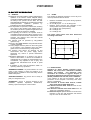
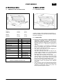
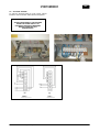
1
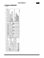
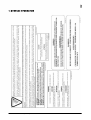
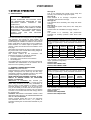
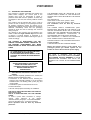
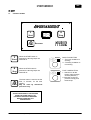
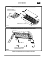
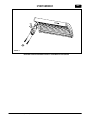
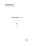
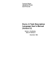
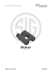
30020 GRUARO-ITALY - VIA DELL’INDUSTRIA 7
Tel. 0421/767676 Fax 0421/767670
INSTALLATION, USE AND MAINTENANCE MANUAL
USA
Cod.man.:11284.136.5.0 (15/04/05)
Cod.app.:10299.028.4.0 (230V ~ 60Hz)
Cod.app.:10297.089.0.0 (230V 3~ 60Hz)
USA
INDEX
INDEX OF SECTIONS
1 - GENERAL INFORMATION
1.1
1.2
1.3
1.4
1.5
Labels
pag. 2
Introduction
4
General tanning instructions
4
Transport and handling
5
Preparation for installation by the client
5
2 - SAFETY INFORMATION
2.1 General
2.2 Noise
2.3 Regulations
6
6
6
3 - TECHNICAL DATA
3.1 Dimensions and technical data HOLIDAY 45
7
4 - INSTALLATION
4.1
4.2
4.3
4.4
Pre-installation
Connections
Assembly instructions
Voltage-change
7
7
8
10
5 - USE
5.1 Control board
5.2 Safety of the persons exposed to UV
11
12
6 - ORDINARY MAINTENANCE MADE BY THE
CUSTOMER
6.1 Ordinary maintenance
13
7 - EXTRAORDINARY MAINTENANCE MADE BY A
SKILLED TECHNICIAN
7.1 Extraordinary maintenance
7.2 Periodic control procedure
15
15
8 - CONTROL BOARD PROGRAMMING
8.1 Electronic control board connections
8.2 Remote controls
18
19
9 - DEMOLITION AND WASTE MATERIALS
9.1 Waste materials
9.2 Demolition of the machine
19
19
10 - REPLACEMENTS AND CIRCUIT DIAGRAMS
10.1 Spare parts list
10.2 Circuit diagrams legend
20
21
11 - MEDICATION
11.1 Medication
22
12 - WARRANTY
12.1 Limited warranty
22
Cod. man.11284.136.5.0 (15/04/05)
1/22
USA
1 - GENERAL INFORMATION
1.1 LABELS
Cod. man.11284.136.5.0 (15/04/05)
2/22
USA
1 - GENERAL INFORMATION
Cod. man.11284.136.5.0 (15/04/05)
3/22
USA
1 - GENERAL INFORMATION
Skin type II.
This is the individual that usually burns easily and
severely. Tans minimally or lightly and peels.
Skin type III.
Often referred to as “average” complexion burns
moderately and tans about average.
Skin type IV.
This individual burns minimally, tans easily and above
average.
Skin type V.
This individual’s system rarely burns, tans easily and
substantially.
Session times are calculated for a supply voltage of
208V.
This product is in conformity with performance
standards for sunlamp products under No.21 CFR
1040.20.
1.2 INTRODUCTION
IMPORTANT
BEFORE OPERATING THE MACHINE, READ
THE INSTRUCTIONS CONTAINED IN THIS
OPERATING MANUAL CAREFULLY AND
COMPLETELY.
KEEP THIS MANUAL AND ALL ENCLOSURES
IN AN ACCESSIBLE PLACE WHERE IT CAN BE
REFERRED TO BY ALL USERS (OPERATORS,
MAINTENANCE PERSONNEL AND THOSE
CLIENTS
WHO
ASK
FOR
DETAILED
INFORMATION).
This Technical Manual is designed for use by installers
and operators, and should be read carefully and
completely before the machine is operated. The manual
should always be available for reference and should be
kept in a safe place so that it stays in good condition for
future reference. For further copies or updates of the
manual, contact the manufacturer at the address on the
front page.
Sportarredo SpA reserves the right to make changes to
the product and to the manual without being obliged to
update the preceding manuals.
This manual contains all the instructions and
information necessary to operate the machine:
• Correct installation of the machine.
• Description of the functions of the machine.
• Circuit diagrams.
The installers and the operators can use this manual to
understand the characteristics of the machine and to
learn the correct operating procedure.
RECOMMENDED EXPOSURE SCHEDULE
First three sessions should be at 48 hour intervals. Followed by the
gradual increasing of exposure times until maximum tanning has
occurred (in approximately 4 weeks). MAXIMUM EXPOSURE is 14
minutes.
Week 1
1st-3rd
Session
Week 2
4rd-6rd
Session
Week 3
7rd-9rd
Session
Subsequent
Weekly
Session
II
III
IV
V
4 min
6 min
10 min
12 min
4 min
6 min
10 min
12 min
4 min
8 min
12 min
14 min
4 min
8 min
12 min
14 min
This schedule is intended to be used with the following
lamps: (standard configuration)
Kalfasun 630F
Kalfasun B23-S WHITE 80W
Kalfasun B23-S WHITE 100W
1.3 GENERAL TANNING INSTRUCTIONS
DANGER! Ultraviolet Radiation.
Follow instructions. Avoid overexposure. As with natural
sunlight, overexposure can cause eye and skin injury
and allergic reactions. Repeated exposure may cause
premature ageing of the skin and skin cancer.
WEAR PROTECTIVE EYEWEAR; FAILURE TO MAY
RESULT IN SEVERE BURNS OR LONG-TERM
INJURY TO THE EYES.
Medications or Cosmetics may increase your
sensitivity to the ultraviolet radiation. Consult physician
before using sunbed if you are using medications or
have a history of skin problems or believe yourself
especially sensitive to sunlight. If you do not tan in the
sun, you are unlikely to tan from the use of this product.
This device is intended to be used by only one person
at a time. Lie on the bed and lower the canopy down to
the stopping point.
CAUTION: EXPOSURE POSITIONS OTHER THAN
SPECIFIED MAY RESULT IN OVEREXPOSURE AND
ARE NOT RECOMMENDED.
Tanning normally begins after one to two exposures
and maximizes after one to four ( 1-4 ) weeks of
exposure following the recommended schedule for your
skin type.
Cod. man.11284.136.5.0 (15/04/05)
Skin
type
RECOMMENDED EXPOSURE SCHEDULE
First three sessions should be at 48 hour intervals. Followed by the
gradual increasing of exposure times until maximum tanning has
occurred (in approximately 4 weeks). MAXIMUM EXPOSURE is 18
minutes.
Skin
type
Week 1
1st-3rd
Session
Week 2
4rd-6rd
Session
Week 3
7rd-9rd
Session
Subsequent
Weekly
Session
II
III
IV
V
4 min
8 min
12 min
14 min
4 min
8 min
12 min
14 min
4 min
10 min
14 min
16 min
4 min
10 min
14 min
18 min
This schedule is intended to be used with the following
lamps: (on demand)
Kalfasun 630F
Kalfasun B14-S Rapid 80W
Kalfasun B14-S Rapid 100W
4/22
USA
1.4 TRANSPORT AND HANDLING
The machine is carefully protected and loaded onto
pallets before shipping. The various parts of the
machine must never be transported or stored in
positions which differ from the positions in which they
are shipped. In this case, the warranty shall be null and
void.
The machine must be handled with care in order to
prevent the risk of damage to the packaged sections.
All handling operations should be carried out by
authorised and trained personnel. When the machine is
delivered, immediately check that the packaging
material is whole and that no damage has occurred
during transport.
Any damage to the machine must be notified to the
carrier not later than eight calendar days from the date
of delivery. If internal damage is suspected, it is
advisable to accept the machine reserving the right to
check accordingly.
THE BREAKER MUST BE INSTALLED IN THE
POWER SUPPLY BOARD OF THE ESTHETICAL
CENTRE AND IT MUST BE DONE BY THE CENTRE
ITSELF.
Mod. HOLIDAY 45:
2x25A-30mA to feed 230V 1phase ~ 60Hz
3x25A-30mA to feed 230V 3phase ~ 60Hz
The installation must be done by technical
personnel.
THE POWER SUPPLY CONNECTION (UNITBOARD) MUST BE DONE BY THE CENTRE. THE
SKILLED TECHNICIAN MUST USE A CERTIFIED
CABLE WITH THE PROPER SECTION AND WITH
ADEQUATE MECHANICAL PROTECTION, IN
ACCORDANCE WITH THE RULES IN FORCE.
SEE CAHAPTER 2.1 TABLES FOR TECHNICAL
DATA “POWER SUPPLY CABLE SECTION”
PLEASE CONTACT THE CUSTOMER SERVICE AT
PHONE NUMBER
1-866-899-4826 FOR ANY FURTHER DOUBT
THE CARRIER IS RESPONSIBLE FOR ANY
DAMAGE OCCURRING DURING TRANSPORT OF
THE MACHINE. SPORTARREDO WILL MAKE
EVERY EFFORT TO ASSIST THE CLIENT IN SUCH
CASES
Before the evening closing, or the closing for a
prolonged period you should operate on the
breaker in order to disconnect the power supply.
ALL MAINTENANCE OF THE MACHINE MUST
BE PERFORMED BY SPECIALIZED
TECHNICIANS FROM SPORTARREDO OR BY
PERSONS AUTHORIZED BY SPORTARREDO
USA INC.
TO HAVE A CORRECT USE OF THE
EQUIPMENT, THE ROOM TEMPERATURE MUST
NOT EXCEED THE 86°F DEGREES. IF ROOM
TEMPERATURE EXCEEDS THIS VALUE, WE
SUGGEST TO UTILIZE AN AIR-CONDITIONING
UNIT.
IMPORTANT !
ALWAYS DISCONNECT THE MACHINE
FROM THE POWER SUPPLY BY
PRESSING THE SWITCH BREAKER
BEFORE CARRYING OUT
MAINTENANCE
1.5 PREPARATION FOR INSTALLATION BY THE
CLIENT
Unless otherwise expressly specified in the contract, the
following must be provided by the client:
• Connections to the electrical circuit, including the
protective wire generally referred to as the "EARTH
CONNECTION", unit feeding cable, power plug and
circuit breaker.
• Canalization system for the emission of hot air.
• External air intake.
• All tools and equipment necessary for installation.
THE UNIT IS SUPPLIED FOR INPUT VOLTAGE AT
230V 1phase 60 Hz
AND IT IS SUPPLIED WITH OUT THE FEEDING
CABLE
To make a power cable connection or voltagechange,
make
reference
to
the
chapter
“INSTALLATION" paragraph “ VOLTAGE-CHANGE ”
and to the HOLIDAY 45 n° 1/4 electrical diagram.
These operation must be done by technical
personnel.
Cod. man.11284.136.5.0 (15/04/05)
5/22
USA
2 - SAFETY INFORMATION
2.1 GENERAL
The employer must ensure that the persons assigned to the
operation of the machine receive adequate training
concerning possible accident risks, the devices fitted for
the safety of the operator and the client, the risks
associated with the emission of UV light and the general
accident-prevention
regulations
specified
by
international norms and local legislation.
Those responsible for operation, maintenance, cleaning
and control of the machine must adhere strictly to
the accident-prevention regulations applicable in the
country in which the machine is installed.
Before operating the machine, the operator must be
completely familiar with the position and the function
of all the controls and with the characteristics of the
machine. The operator must read this manual
carefully and completely.
The machine must be operated by fully-qualified
operators only.
Removal of the safety devices and protective barriers
is strictly forbidden.
No heavy weights must be placed on the moving parts
of the machine. The ventilation ducts and intake
grilles must not be obstructed by foreign bodies.
The machine must always be switched off and
disconnected from the power supply before
performing any routine or special maintenance
operations.
Unauthorised replacement of or repairs to any part or
section of the machine, or the use of accessories or
material that are not original or recommended by the
manufacturer, may represent a risk of injury, and
exonerate the manufacturer from all civil or penal
liability.
It is forbidden to stay near the appliance while it is
operating without eye protection.
"DANGEROUS ZONES": any zone internal to or in the
vicinity of the machine in which the presence of an
exposed person constitutes a risk for the safety and the
health of that person.
"EXPOSED PERSON": any person who is wholly or
partly in a dangerous zone.
"OPERATOR": person or persons assigned to the
installation, operation, adjustment, maintenance,
cleaning, repair and transport of the machine.
Cod. man.11284.136.5.0 (15/04/05)
6/22
2.2
NOISE
The machine is designed and built in such a way as to
reduce operational noise as follows:
•
Effective normalized sound power during operation,
see diagram below:
1 = 2 = 62 dB (A) max 3 = 4 = 65 dB (A) max
• Effective sound pressure with simulation of the
actual position of the person being treated:
A = 74 dB (A) max. (head position)
B = 76 dB (A) max.
C = 76 dB (A) max.
The figures shown above have been determined
according to ISO 3746.
4
1
1m
1m
1m
1m
C
B
1m
A
1m
1m
1m
3
FRONT SIDE
2
2.3 REGULATIONS
Standard for Safety Portable Sun/Heat Lamps,
ANSI/UL 482, Ed:8, Issue: 1999-05-28 & Radiant
Heaters and Infrared
and Ultraviolet Lamp
Assemblies for Cosmetic or Hygienic Purpose in
Nonmedical Applications General Instruction No 1-2
(R1999), CAN/CSA C22.2 No.224, Issue: 1989/09/01.
In the planning of this unit the following rules and
provisions of the European Community have been
taken in consideration:
ECC Directive N. 91/368 dated 20.06.91, N.93/44
dated 14.06.1993, N.93/68 dated 22.07.
ECC Directive N.73/23 dated 19.02.73 known as “low
voltage directive”.
ECC Directive N.89/336 dated 03.05.1989 known as
“Electronic compatibility directive”.
En 60335-2-27 II part Special standard for units for the
treatment of the skin with ultraviolet and infrared
rays for home use and similar use.
USA
3 - TECHNICAL DATA
4 - INSTALLATION
3.1 DIMENSIONS AND TECHNICAL DATA
4.1 PRE-INSTALLATION
HEIGHT
135 cm
53" in
LENGTH
213 cm
84" in
WIDTH
99 cm
39" in
WEIGHT
235 Kg
518 lb
In order to ensure correct operation of the machine, it
should be installed in an area which has been prepared
as shown in the figure.
4.2 CONNECTION
HOLIDAY 45
POWER SUPPLY
V
POWER ABSORPTION
CURRENT ABSORPTION
POWER FACTOR
CORRECTION
FREQUENCY
WIRE SIZES
NUMBER OF WIRE
REQUIRED
HEAT PRODUCED
U.M
DATA
230V ~
230V 3~
KW
4,7
4,4
A
21,3
12,9
0.97
Hz
60
AWG
9
11
3
4
Kcal/h
4000
FACE LAMPS
N.
2x KALFASUN 630F
CANOPY LAMPS
N.
BASE LAMPS
N.
16x KALFASUN
B23-S White 80W
16x KALFASUN
B23-S White 100W
UV EMISSION
SEE RAY EMISSION CERTIFICATE
Cod. man.11284.136.5.0 (15/04/05)
7/22
The area in which the machine is installed must be
adequately ventilated, fit the area with an air
intake from outside if necessary. To improve the
technical comfort we suggest to connect the tube to
expel the hot air to a fixed duct to expel the air
outward
• The metal structure of the machine is earthed by
means of insulated wires connected to the earth
terminal in the electrical junction box.
• The earth circuit must be in full compliance in
accordance with the rules in force.
• The earth connection must also be fitted to lowvoltage systems situated in wet or very damp areas
(if the voltage to earth is in excess of 25V for
alternating current or 50V for direct current).
• The earth wires connected to every part of the
various sections of the machine and the earth wires
from the various power circuits and user groups
must be connected to a single earthing circuit.
• Ensure that the materials used for the earth system
are suitably robust and provided with adequate
protection.
• The connection to the main earth terminal should be
as short as possible. The earth wires should not be
subjected to mechanical stress of any kind, and
must be protected against corrosion.
USA
4.3 ASSEMBLY INSTRUCTIONS
SEE ENCLOSED TABLE 1
1
Place the two supports A at a distance of approx. 1
metre one from the other.
2
Put the base B on the supports A and make the
front and back holes A1 coincide with the holes of
the base. Insert the 8x30 screws with washer of 8 in
A1.
3
Place the boomerang right and left, upper and lower
supports C on the base B and the sky D with the
8x13 flared screws.
4
Place the head D on the base B at points C1
inserting the 8x30 screws with washer with teeth,
washer of 8 and teflon washer. See fig. 1a.
5
Fix the lateral pistons E. Place the piston E
(500/600 Newton) from the intensive part. See fig.
1b.
6
Insert the feeder box F from the back part and fix
with the 4.8x13 with large head screws the feeding
base cable in F1, feeding box in F2, feeding head in
F3.
7
Fix the rear panel G and the two supports G1 with
the specific 4.8x13 with large head screws. See fig.
1c.
8
Place the ventilator box on the sky with the two
4x20 with cross head screws.
9
Place the frontal panel I with the 4 specific 3,9x9,5
with large head screws in the lateral sides.
10 Place the abs “Sportarredo” frontal panel H with the
specific 4.2x32 screws in the lateral sides.
Cod. man.11284.136.5.0 (15/04/05)
8/22
USA
TABLE 1
Cod. man.11284.136.5.0 (15/04/05)
9/22
USA
4.4 VOLTAGE CHANGE
To enter the terminal board for power supply, placed
inside the control cassette, make reference to photos.
IMPORTANT !
ALWAYS DISCONNECT THE MACHINE
FROM THE POWER SUPPLY BY
PRESSING THE SWITCH BREAKER
BEFORE CARRYING OUT
MAINTENANCE
Cod. man.11284.136.5.0 (15/04/05)
10/22
USA
5 - USE
5.1
CONTROL BOARD
I
0
Start
Stop
min
Time
I
Start
0
Stop
Decrease
When the START button is
pressed, the tanning lamps are
switched on.
I
0
When the STOP button is
pressed, the tanning lamps are
switched off.
I
0
Time
The time button is used to set the
time, in minutes, for the time
session.
May be used by authorised
personnel only.
IMPORTANT !
ALWAYS DISCONNECT THE MACHINE
FROM THE POWER SUPPLY BY
PRESSING THE SWITCH BREAKER
BEFORE CARRYING OUT
MAINTENANCE
Cod. man.11284.136.5.0 (15/04/05)
11/22
BODY FAN BUTTON
I – The body ventilation is
working.
0 – The body ventilation is
not working.
FACE LAMP BUTTON
I - Switches on all the
lamps ( high-pressure
and low-pressure ).
0 Switches on the lowpressure canopy and
base lamps.
USA
5.2 SAFETY OF THE PERSONS EXPOSED TO UV
Don’t use the unit in case of filter damages and
timer faults!
ATTENTION!
AN IMPROPER OR INCORRECT USE OF THE
UNIT CAN CAUSE SERIOUS BODILY
DAMAGES TO THE PERSON EXPOSED!
1)
2)
3)
4)
5)
From a careful analysis, as specified in EN
60335-2-27, the precautions that must be
observed are listed below.
If the client is undergoing treatment using
medication, such as antibiotics or antiinflammatory pharmaceuticals, it is advisable to
suspend tanning sessions.. In any case, it is
advisable to consult a doctor.
Before a tanning session, the skin should be clean
and free of cosmetics or perfumes.
Be sure not to exceed the exposure times
selected by the staff of the tanning centre.
Always use the special protective eyewear. The
eyes must under no circumstances remain open
during the tanning session.
After each tanning session, it is advisable to apply
a moisturising cream.
1
2
It’s advisable to:
• Not exposure any part of the body more than one time
per day.
• Not exposure to the unit and sun in the same day.
• Do not expose yourself to the appliance if you usually
burn with normal sunlight or if you suffer from sunrash.
• Do not make UV session in case of pregnancy. In any
case please consult your own attending physician
before making the session.
• Do not expose to UV immediately after depilation
treatments.
• Do not expose children or adults that are prone to or
are suffering (or have previously suffered) from skin
neoplasia.
• Consult the physician if on the skin swellings,
ulceration's or red spots appear.
3
ATTENTION!
• Ultraviolet radiation may cause injury to the eyes
and skin, such as skin ageing and eventually skin
cancer.
• Read instructions carefully.
• Wear the protective goggles provided.
• Certain medicines and cosmetics may increase
sensitivity.
4
A copy of the following warnings is supplied with the
manuals and must be shown to the public close to the
unit.
Cod. man.11284.136.5.0 (15/04/05)
5
12/22
USA
6 - ORDINARY MAINTENANCE MADE
BY THE CUSTOMER
6.1 ORDINARY MAINTENANCE
IMPORTANT !
ALWAYS DISCONNECT THE MACHINE
FROM THE POWER SUPPLY BY
PRESSING THE BREAKER SWITCH
BEFORE
CARRYING
OUT
MAINTENANCE
Every 100 hours of operation make the following
ordinary maintenance operations:
- Cleaning of internal and external acrylics.
- Cleaning of cobalt and transparent filters.
IMPORTANT!
USE ONLY THE DISINFECTANT CLEANSING
MULTYSAN TO CLEAN THE ACRYLIC
N.B. DO NOT USE ALCOHOL OR ALCOHOL-BASED
PRODUCTS FOR CLEANING
REMOVING AND CLEANING THE ACRYLIC PANEL
AND BLUE COBALT FILTER
To make the cleaning of the acrylics and the cobalt
filters it’s necessary to make as follows on Table 2-3.
CHECK OF THE BLUE COBALT FILTER
To prevent the exposition to bad rays it's important to
check the good conditions of the blue cobalt filters and
the fixing condition to the metallic frame. If breaks or
cracks are present do not use the equipment and call
for a skilled technician maintenance.
CLEANING THE TRANSPARENT AND BLUE
COBALT FILTERS
Clean the filters internally and externally using a 50%
solution of water and denatured alcohol.
ANY TAMPERING WITH THE APPLIANCE OR
THE USE OF NON-ORIGINAL MATERIAL OR
PARTS MAY LEAD TO INJURY. IN SUCH
CASES, THE MANUFACTURER DECLINES ALL
CIVIL AND PENAL LIABILITY, AND THE
WARRANTY SHALL AUTOMATICALLY BE
CONSIDERED NULL AND VOID.
FILTERS USED IN THIS APPLIANCE:
Cobalt filter 230x75mm Sp.1.6 mm
Filter Superlux TR-T 240x210 mm
REFLECTORS USED IN THIS APPLIANCE:
S630
Cod. man.11284.136.5.0 (15/04/05)
13/22
USA
REMOVING AND CLEANING THE ACRYLICS PANEL FITTED TO THE BASE
RAISE WITH THE HANDS THE
PROFILE TO CLOSE THE
ACRYLIC IN ALL ITS LENGTH
A
B
B1
PUSH THE ACRYLIC TOWARDS
B1 AND RAISE IT
TABLE 2
REMOVING AND CLEANING THE ACRYLICS PANEL FITTED TO THE CANOPY
D
B
C
A
UNSCREW THE 3 SCREWS ABC
TO RAPID RELEASE AS SHOW IN
SEQUENCE HOLDING ACRYLIC
TABLE 3
PERFORM THIS PROCEDURE IN STRICT ALPHABETICAL SEQUENCE
Cod. man.11284.136.5.0 (15/04/05)
14/22
USA
7 - EXTRAORDINARY MAINTENANCE
MADE BY A SKILLED TECHNICIAN
ANY TAMPERING WITH THE APPLIANCE OR
THE USE OF NON-ORIGINAL MATERIAL OR
PARTS MAY LEAD TO INJURY. IN SUCH
CASES, THE MANUFACTURER DECLINES ALL
CIVIL AND PENAL LIABILITY, AND THE
WARRANTY SHALL AUTOMATICALLY BE
CONSIDERED NULL AND VOID.
7.1 EXTRAORDINARY MAINTENANCE
Every 400 hours of operation make the following
extraordinary maintenance operations:
• Cleaning of internal and external acrylics.
• Replacement of high-low pressure lamps.
• Check that the timer system is working correctly.
• Check that the USE instructions are legible and in
satisfactory condition.
• Every 800 working hours replace the reflectors, the
igniters for the high-pressure lamps and the starter
for the low-pressure lamps.
• Clean the fans and the inside of the machine.
• Every 1200 working hours replace the acrylics.
MAINTENANCE OF INTENSIVE FAN COOLER
7.2 PERIODIC CONTROL PROCEDURES
Electrical checks. Check that the electrical safety
devices, and the acoustic/illuminated signal devices and
alarms are undamaged and that they function correctly.
Check that the equipment and devices in the electrical
control box are in satisfactory condition.
These checks must be performed by qualified
personnel
IMPORTANT !
ALWAYS DISCONNECT THE MACHINE
FROM THE POWER SUPPLY BY
PRESSING THE BREAKER BEFORE
CARRYING OUT MAINTENANCE
IMPORTANT!
USE ONLY THE DISINFECTANT CLEANSING
MULTYSAN TO CLEAN THE ACRYLIC
N.B. DO NOT USE ALCOHOL OR ALCOHOL-BASED
PRODUCTS FOR CLEANING
CHECK OF THE BLUE COBALT FILTER
To prevent the exposition to bad rays it's important to
check the good conditions of the blue cobalt filters and
the fixing condition to the metallic frame. If breaks or
cracks are present do not use the equipment and call
for a skilled technician maintenance.
Remove the acrylic.
Loosen the screw 4.8x13 on the point A.
Loosen the widened screws 8x45 on the points BCD.
At this point the piston E gets loose and comes out of
some millimetres.
Take the plastic F out from its positions as much as
possible.
Unscrew the two screws G that support the intensive I.
Disconnect the wires of the lamps, the ignites and the
fan, then take this one out by unscrewing the 4 screws
3.9x45, H.
To take off more easily the fan positioned in the
intensive, we suggest to disassemble completely the
canopy.
CLEANING THE BLUE COBALT FILTERS
Clean the filters internally and externally using a 50%
solution of water and denatured alcohol.
Cod. man.11284.136.5.0 (15/04/05)
15/22
USA
REPLACING THE FILTERS, REFLECTOR AND HIGH-LOW PRESSURE LAMPS
REFLECTOR S 630
Cod.14073.016.1.0
LAMP KALFASUN 630F
Cod.4028.4002.00
D
16xKALFASUN B23-S White 80W
Cod.4028.4009.00
B
C
A
UNSCREW THE 3 SCREWS ABC
TO RAPID RELEASE AS SHOW IN
SEQUENCE HOLDING ACRYLIC
TABLE 4
REPLACING THE BASE LAMPS
RAISE WITH THE HANDS THE PROFILE
TO CLOSE THE ACRYLIC IN ALL ITS
LENGTH
A
B
B1
PUSH THE ACRYLIC TOWARDS
B1 AND RAISE
16xKALFASUN B23-S White 100W
Cod.4028.4009.01
TABLE 5
PERFORM THIS PROCEDURE IN STRICT ALPHABETICAL SEQUENCE
Cod. man.11284.136.5.0 (15/04/05)
16/22
USA
REPLACING BODY FAN
A
TABLE 6
PERFORM THIS PROCEDURE IN STRICT ALPHABETICAL SEQUENCE
Cod. man.11284.136.5.0 (15/04/05)
17/22
USA
8 - CONTROL BOARD
PROGRAMMING
8.1 ELECTRONIC CONTROL BOARD
CONNECTIONS
F
N
L
V
4
A
3
2
1
B
GRUARO-ITALY
TMK/1
CONTROL BOARD
I
0
Start
Stop
Time
Decrease
min
CIRCUIT BOARD TERMINALS: NUMBERING AND
DESCRIPTION
F=
Power supply phase.
N=
Power supply neutral.
L=
Control phase for lamp.
V=
Control phase for fans.
TIMES REGULATION OF THE SESSION
Session time adjustment through microswitch 1-2-3-4
following the combination shown in the table.
It isn’t possible to regulate the cooling time after the
session it is programmed at 4 minutes.
Card is provided of protection fuse.
1
2
3
4
TIME (MIN.)
1
2
3
4
TIME (MIN.)
OFF
OFF
OFF
OFF
OFF
OFF
OFF
ON
ON
OFF
OFF
OFF
ON
OFF
OFF
ON
OFF
ON
OFF
OFF
6
8
10
12
14
16
18
20
OFF
ON
OFF
ON
22
24
26
28
30
32
34
36
ON
ON
OFF
OFF
OFF
OFF
ON
OFF
ON
OFF
ON
OFF
OFF
ON
ON
OFF
ON
ON
ON
OFF
Cod. man.11284.136.5.0 (15/04/05)
18/22
ON
ON
OFF
ON
OFF
OFF
ON
ON
ON
OFF
ON
ON
OFF
ON
ON
ON
ON
ON
ON
ON
USA
8.2 REMOTE CONTROLS
•
Connect the two wires of the coin box G to the terminals
L1 and N of the terminal board CN.G placed on the
base. See " HOLIDAY 45_n°4/4 " circuit diagram.
With this connection the external push-button
“START” will be automatically cut off from its
function and the unit ignition will be possible only
through coin box. Putting one or more coins, there
will not be an accumulation of the prefixed time. The
solarium ignites with a certain delay after the
introduction of the coin. It is possible to regulate the
delay time.
Terminals L1 and L2 of the terminal board CN.G
are used for enable start.
Numbers L1 and L3 of the terminal board CN.G
are used for remote stop. ( Stop ).
To permit this function make follow these steps.
• Remove the small bridge to terminals numbered
L1 - L2 of the terminal board CN.G.
See " HOLIDAY 45_n°4/4 " circuit diagram.
• Remove the small bridge B from the TMK/1
electronic board.
• Connect the wires of the coin box G to the
numbers L1 and N of the terminal board CN.G.
G
E
•
L1 L2
•
N
L3
Make follow these steps.
• Take off voltage from the unit.
• Push and keep pushed the “TIME” button of the
control panel and at the same time give voltage
to the unit.
• Adjust the delayed time acting on the trimmer
placed in the TMK/1 electronic board.
• Take off voltage from the unit.
COIN ACCUMULATION FUNCTION
To permit this function make follow these steps.
• Remove the small bridge to terminals numbered
L1 - L2 of the terminal board CN.G.
See " HOLIDAY 45_n°4/4 " circuit diagram.
• Remove the small bridge A from the TMK/1
electronic board.
• Connect the wires of the coin box G to the
numbers L1 and N of the terminal board CN.G.
COIN ACCUMULATION FUNCTION AND START
WAITING
With this connection when putting one or more
coins, there will be an accumulation of the prefixed
time. The solarium ignites through the “START”
push button of the control board.
9 - DEMOLITION AND WASTE
MATERIALS
9.1 WASTE MATERIALS
The lamps are considered as disposable waste
materials and all the materials regarding the packing.
Due to their characteristics, these lamps are classified
as non-toxic and non-harmful special waste materials.
Disposal of the lamps must therefore be effected as
required by the appropriate legislation.
DEFINITION OF SPECIAL WASTE MATERIAL:
Residual material deriving from industrial processes or
agricultural, artisan, commercial or service activities
which, in view of their quantity of characteristics, are not
classified as normal household refuse.
9.2 DEMOLITION OF THE MACHINE
To permit this function make follow these steps.
• Remove the small bridge to terminals numbered
L1 - L2 of the terminal board CN.G.
See " HOLIDAY 45_n°4/4 " circuit diagram.
• Remove the small bridge A and B from the TMK/1
electronic board.
• Connect the wires of the coin box G to the
numbers L1 and N of the terminal board CN.G.
Cod. man.11284.136.5.0 (15/04/05)
ADJUSTMENT OF THE DELAY TIME
It is possible to adjust the delay time of the delayed
ignition function.
CN.G
With this connection the external push-button
“START” will be automatically cut off from its
function and the unit ignition will be possible only
through coin box. Putting one or more coins, there
will be an accumulation of the prefixed time. The
solarium ignites just immediately after the
introduction of the first coin.
•
DELAYED IGNITION FUNCTION
19/22
Each country applies specific legislation concerning the
disposal of machinery. Disposal of this machine must
be carried out in compliance with the regulations laid
down by local legislation and bye-laws. Dismantle the
machine and group the various parts according to their
chemical characteristics.
Dismantling of the machine must be performed by
qualified personnel
USA
10 - REPLACEMENTS AND CIRCUIT
DIAGRAMS
10.1 SPARE PARTS LIST
REF
1
2
3
4
PC CODE
4028.1001.06
16
4028.1001.05
16
16973.000.0.0
2
4028.4300.00
6
5
1
4028.4304.00
6
1
4028.2100.04
7
1
4028.2100.00
8
1
4028.4500.01
9
1
4028.4550.01
10
11
12
4
2
1
4028.0021.00
4028.0029.04
4028.3250.00
13
14
15
1
2
16
4028.3200.11
14073.016.1.0
4028.4009.01
16
16
4028.4009.00
17
18
19
2
2
32
4028.4002.00
4028.4400.04
4028.3310.00
20
21
22
23
32
32
2
6
4028.3310.01
4028.4020.03
16976.003.0.0
16976.004.0.0
24
25
26
1
1
1
16946.109.2.0
16946.121.2.0
4028.5511.00
27
1
4028.5611.00
28
29
30
31
32
33
34
35
36
37
38
39
1
1
1
1
4
1
1
1
1
2
2
1
15906.000.0.0
16906.003.0.0
4028.6000.01
4025.2302.02
4023.4000.06
4025.7000.19
4025.7000.18
16916.000.0.0
15943.006.0.0
16946.105.0.0
16946.106.0.0
16946.118.0.0
40
1
14703.020.1.0
DESCRIPTION
100W 60Hz BALLAST
80W 60Hz BALLAST
MYSUN 600W BALLAST
41
42
2
1
4028.2181.00
16986.096.0.0
CONDENSER 65 µF 400 V
43
1
16986.136.0.0
44
45
46
47
48
49
1
1
2
1
1
2
16946.113.2.0
16946.114.2.0
16936.012.1.0
16946.111.3.0
16946.112.3.0
4024.0010.03
CONDENSER 20 µF
LAMPS CONTACTOR FANTINI &
COSMI HR1710
LAMPS CONTACTOR FANTINI &
COSMI HR0910
CONTROL RELAY FOR COOLING
FAN UNIT FINDER 60.13
UNDECAL RELAY SOCKET
FINDER 90.27
EBM W2S130 AA0301 FAN
EBM 4650N FAN
TERMINAL BOARD 12 PINS
16MM²
TERMINAL BOARD PA44 12 PINS
S 630 REFLECTOR
LAMP KALFASUN B23-S
WHITE 100W
LAMP KALFASUN B23-S
WHITE 80W
KALFASUN 630F
IGNITER ZRM6
NEON HOLDER WITHOUT
STARTER
NEON HOLDER WITH STARTER
STARTER PHILIPS S12
SUPERLUX TR-T 240X210 FILTER
COBALT FILTER
(DIMENSIONS 230 X 75 X 1.6)
BASE ACRYLIC
CANOPY ACRYLIC
BLACK PLUG WITH 3 PINS
ST18/5 S
BLACK SOCKET WITH 3 PINS
ST18/5 B1
“TMK/1” CONTROL BOARD
POLYCARBONATE KEYBOARD
HOUR COUNTER REVALCO
WHITE HANDLE
WEELS
GAS SPRING 600N
GAS SPRING 500N
CUSHION
COVERING FAN YELLOW
COVERING RIGHT ABS YELLOW
COVERING LEFT ABS YELLOW
COVERING YELLOW TIMER
BOARD
T.MAX CONTROL BOARD CTM/1
Cod. man.11284.136.5.0 (15/04/05)
20/22
GREEN BUTTON D.25
FACE STICKER AROUND THE
GREEN BUTTON
FAN STICKER AROUND THE
GREEN BUTTON
CONTROL BOARD PROFILE
REAR PROFILE BASE
ACRYLIC FLAP BASE
FRONT PROFILE CANOPY
REAR PROFILE CANOPY
UVA EYEWEAR
USA
10.2 CIRCUIT DIAGRAMS LEGEND
SIMBOLS
G
1AL – 16AL
4028.1001.05
AC
4028.4400.04
AL
4028.1000.02
B1-B16
4028.1001.06
C1-C2-C3
4028.4300.00
C4
4028.4304.00
CN.G
4028.5511.00
CO
4028.6000.01
F-N = L1-L2
I
4028.2181.00
Int.
4028.2181.00
HR
4028.2100.04
HR1
4028.2100.00
L1
4028.4009.01
L2
4028.4009.00
LAP
4028.4002.00
MA
MB
MB/1
MT
MT/1
MT/2-3-5-6
RV
4028.4500.01
S
4028.4020.03
Tast.
16906.003.0.0
TMK/1
15906.000.0.0
V
4028.0029.04
V1
4028.0021.10
CTM/1
14703.020.1.0
W1
DESCRIPTION
Earth terminal
Ballast for lamp Kalfasun B23-S White
80W
Igniter for lamp Kalfasun 630F
Ballast for lamp Kalfasun 630F
Ballast for lamp Kalfasun B23-S White
100W
Power factor correction capacitor 65µF
Capacitor 20µF
Terminal board for connection of remote
control unit
Hour-counter
Phases of power supply
Body fan button
Face lamp button
Contactor for low pressure lamps
Contactor for low pressure lamps
Kalfasun lamps B23-S White 100W
Kalfasun lamps B23-S White 80W
Kalfasun lamps 630F
Terminal board for power supply
Connector for base ( 10 pins )
Terminal board for base ( 12 pins )
Connector for canopy ( 24 pins )
Terminal board for canopy ( 24 pins )
Terminal board mammuth ( 3 pins )
Control relay for cooling fan unit
Starter
Polycarbonate keyboard
Control board TMK/1
Cooling fan for base and canopy
Cooling fan for high pressure lamp
T. Max control board
Terminal board for external connection
DESCRIPTION CIRCUIT DIAGRAMS
1/4 Voltage-change diagram.
2/4 Practical diagram ballasts cassette.
3/4 Practical diagram of canopy.
4/4 Practical diagram of base.
Cod. man.11284.136.5.0 (15/04/05)
21/22
USA
11 - MEDICATION
12 - WARRANTY
11.1 MEDICATION
12.1 LIMITED WARRANTY
Certain drugs can make your skin sensitive to ultraviolet
light. The U.S. Department of Health and Human
Services has published a booklet entitled Medications
That Increase Sensitivity to Light; A 1990 Listing
prepared by Jerome: Levine, M.S., R.Ph: The booklet is
HHS Publication FDA 91-8280 and is available from the
U.S. Government Printing Office: Refer to this booklet
or your health practitioner if you are taking any
medications.
For USA see next page.
Dr. Richard Childers and Dr. Edward Emmett of Jhon
Hopkins University complied a list of drugs, foods, and
other substances that could make your skin sensitive to
ultraviolet light: This list is presented below:
•
Diuretics ( which help prevent water retention ),
prescribed for high blood pressure ( for example,
Hydrodiuril ).
•
Diabetes drugs-Orinase and Diabinase.
•
Urinary
tract
infection
treatments
with
phenothiazines.
•
Tranquilizers, such as Thorazine.
•
The acne treatment Retin-A.
•
Anthistamines-Phenergan
and
Benadrylparticularity when they are used on the skin in
ointment form.
•
Antibiotics-Declomycin,
Aureozicin,
and
Griseofulvin, which is use in ringworm treatment.
•
Coal tar treatment for psoriasis or chronic eczema.
•
Bacterial infection treatments using sulfanilamide.
•
Compounds known as furocoumarins or psoralens,
which sensitise skin to sunlight whether put on the
skin or taken orally. They are prescribed for vitiligo
( loss of skin pigmentation ) and psoriasis.
•
Birth control pills. The hormones they contain can
react with sunlight and in some cases cause brown
patches on the skin.
•
Perfumes and colognes containing furocoumarins,
compounds from natural products such as plants
and fruits. Their natural oils cad sensitise the skin
to sunlight.
•
Food and fruits that contain photosensitising
agents: celery, carrots, limes, coriander, parsley,
fennel, dill, buttercup, mustard and figs.
Cod. man.11284.136.5.0 (15/04/05)
22/22
TERMS OF WARRANTY
Sportarredo USA, Inc. (“Sportarredo”) warrants its
tanning beds (the “Products”) to be free from defects in
materials and workmanship under intended normal use
as described in the unit's Operation and Instruction
Manual, for a period of two (2) years (the Warranty
Period”) from date of sale (proved by the invoice’s
date). This Limited Warranty does not cover the normal
wear and tear of the Products.
This Limited Warranty applies only within the United
States and Canada to the first end user (the “Buyer”) of
the Products and becomes void on the transfer or sale
of the Products to any party other than the Buyer.
I. Registration Requirement
a. This Limited Warranty becomes effective only if the
Buyer fills out and returns the Warranty Certificate,
dated and signed by the Buyer, to Sportarredo at the
address shown below within thirty (30) days of the sale
of the Products.
b. By returning the Warranty Certificate to Sportarredo,
the Buyer acknowledges to have fully read and
understood the user’s manual, and to have complied
with all the instructions stated in that document.
II. Installation and Maintenance Requirements
a. This Limited Warranty does not apply when the
installation has not been performed by Sportarredo’s
trained and certified technician. For the sake of clarity,
the technicians have to be certified by Sportarredo,
after attending Sportarredo’s training courses.
b. This Limited Warranty does not apply if the Products
are misused or abused, and there is evidence of
mishandling, neglect, modification or repair without the
approval of Sportarredo, or damage done to the
Products by anyone other than Sportarredo.
c. This Limited Warranty does not apply to damages
caused during transportation (including transport to and
from the Buyer's location); or damage due to improper
or lack of maintenance; voltage overloads or “under
voltage”; insufficient or abnormal operation of electrical
or hydraulic systems; improper or incorrect treatment of
water supply; or corrosion caused by condensation or
hard water; improper descaling treatments; or in
general to any cause which does not specifically
depend on defect in material or workmanship.
d. This Limited Warranty does not apply if the serial
number on the product has been removed, altered or
defaced.
III. Warranty Claim Procedure
In order to submit a Warranty Claim, the Buyer must
provide Sportarredo with a written notice of any alleged
defects within the Warranty Period, but in any case
after no more than ten (10) days from the date of the
discovery of the defects. At Sportarredo’s option, the
Buyer must ship the defective Product(s) to
Sportarredo, at the address shown below, with mailing
or shipping charged prepaid. Sportarredo shall be liable
for and shall pay for the all freight, shipping and delivery
costs of forwarding parts sent to Sportarredo for repair
or replacement under the Limited Warranty. The Buyer
shall be liable and pay for all labor and transportation
charges in the event of a house call by an unauthorized
technician. Adequate packaging must be used for
returned goods to prevent freight damages.
IV. Warranty Services
a. Defective parts will be replaced upon receipt by
Sportarredo. Only original parts obtained through
Sportarredo USA Inc., its authorized dealers or
distributors may be used. Shipping terms, methods, etc.
must be pre-approved by Sportarredo prior to the return
of the parts in question. Parts, etc. shipped to
Sportarredo without prior approval will be refused and
the owner/shipper will be responsible for all related
shipping costs etc.
b. If the Products shall be proved to Sportarredo's
satisfaction to be defective within the Warranty Period,
Sportarredo’s obligation under this Limited Warranty
shall be limited to either repairing or replacing the
Products, at Sportarredo’s sole discretion, if such defect
was caused solely by defective workmanship and
materials. Such repair or replacement shall be
Sportarredo’s sole obligation and the Buyer’s exclusive
remedy hereunder and shall be conditioned upon the
Buyer’s fulfilling of its obligations under Warranty
Claims Procedure. The obligations under this warranty
are limited to repair or replacement of any defective
part without charge for that part to the original
purchaser, with the following exceptions:
1. Tanning lamps, filters, starters and igniters are
warranted against defects for a period of sixty (60) days
from date of sale.
2. Radios and speakers are warranted by the radio and
speaker Sportarredo for the period of time indicated in
their warranty certificates.
3. Labor will be furnished without charge for sixty (60)
days from the date of purchase only. All labor and
related charges must be authorized by Sportarredo
USA Inc. prior to start of repairs, and must conform with
Sportarredo USA Inc. established rates and time
allotment policy.
4. All fans and batteries are warranted against defects
for a period of two (2) years from date of sale.
5. Timer system, plastics reflectors and parts subjected
to “normal” wear & tear (meaning parts intended to be
used by the final customer during each session, as
buttons, switches, profiles, etc) are warranted for one
(1) year.
6. Acrylics are warranted for twelve (12) month prorated
period (this warranty applies only if the “owner” of the
units has used appropriate cleaners).
7. Mattresses and pillows are warranted for a period of
six (6) months from the date of sale.
V. Exclusion from Limited Warranty
The following are not covered by this Limited Warranty
Scratches, splinters, or marks to the Products, unless
Sportarredo is notified as soon as the Products are
received by the Buyer;
Normal wear and tear;
Defects not caused by the Products, but that are the
result of improper installation;
Misuse or abuse by the Buyer;
Physical damage to the Product as a result of
unreasonable use and/or negligence.
Sportarredo USA Inc. – 2224 Commerce Drive, Arlington, TX 76011 – 1 866 899 4826 fax 1-866-487-6486
VI. Limitations on Warranty
This Limited Warranty is provided by Sportarredo, and it
contains the only express warranty provided to the
Buyer by Sportarredo. Sportarredo does not authorize
any other person, including distributors, subdistributors, agents, to give any other warranties on
Sportarredo’s behalf.
SPORTARREDO
DISCLAIMS
ANY
EXPRESS
WARRANTY NOT PROVIDED HEREIN AND ANY
IMPLIED
WARRANTY,
GUARANTY
OR
REPRESENTATION
AS
TO
PERFORMANCE,
QUALITY AND ABSENCE OF HIDDEN DEFECTS,
AND ANY REMEDY FOR BREACH OF CONTRACT,
WHICH BUT FOR THIS PROVISION, MIGHT ARISE
BY IMPLICATION, OPERATION OF LAW, CUSTOM
OF TRADE OR COURSE OF DEALING, INCLUDING
IMPLIED WARRANTIES OF MERCHANTABILITY
AND FITNESS FOR A PARTICULAR PURPOSE.
SPORTARREDO
FURTHER
DISCLAIMS
ANY
RESPONSIBILITY
FOR
LOSSES,
EXPENSES
INCONVENIENCES,
SPECIAL,
INDIRECT,
SECONDARY OR CONSEQUENTIAL, INCIDENTAL,
AND CONTINGENT DAMAGES WHATSOEVER,
INCLUDING
DAMAGES
ARISING
FROM
OWNERSHIP OR USE OF PRODUCT.
Implied warranties in jurisdictions where they may not
be disclaimed shall be in effect only for the duration of
the express warranty set forth herein.
If the Buyer has a claim under this Limited Warranty or
under any implied warranties provided to the Buyer by
state law, the Buyer may not file a court action based
on that claim any later than one (1) year after the
Buyer’s right to file a court action accrues. In those
states that do not allow this limitation on the time period
for filing a court action, this provision is inapplicable.
VII. Sportarredo’s Liability
a. Sportarredo’s liability with respect to the Product sold
to the Buyer shall be limited to the Limited Warranty
provided herein. Sportarredo SHALL NOT BE
SUBJECT TO ANY OTHER OBLIGATIONS OR
LIABILITIES, WHETHER ARISING OUT OF BREACH
OF CONTRACT, WARRANTY, TORT (INCLUDING
NEGLIGENCE AND STRICT LIABILITY) OR OTHER
THEORIES OF LAW, WITH RESPECT TO THE
PRODUCTS SOLD OR SERVICES RENDERED BY
SPORTARREDO, OR ANY UNDERTAKING, ACTS OR
OMISSIONS RELATING THERETO.
b. Without limiting the foregoing, Sportarredo
specifically disclaims any liability for property or
personal injury damages, penalties, special or punitive
damages, damages for lost profits or revenues,
services, down time, shut down or slow down costs, or
for any other types of economic loss, and for claims of
the Buyer’s customers or any third party for any such
damages. Sportarredo SHALL NOT BE LIABLE FOR
AND
DISCLAIMS
ALL
CONSEQUENTIAL,
INCIDENTAL,
AND
CONTIGENT
DAMAGES
WHATSOEVER.
Sportarredo USA Inc. – 2224 Commerce Drive, Arlington, TX 76011 – 1 866 899 4826 fax 1-866-487-6486