1
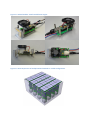
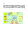
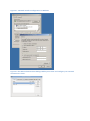
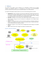
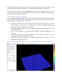
Relaxd module User Instructions & Software Manual Author: Vincent van Beveren, Henk Boterenbrood, Martin Hejtmánek Nikhef Amsterdam Version 0.1 , Novermber 3 , 2011 Table of contents 1 Introduction ..................................................................................................................................... 3 2 Hardware ......................................................................................................................................... 5 3 Connecting a Relaxd module ........................................................................................................... 6 3.1 3.1.1 Windows ............................................................................................................................ 6 3.1.2 Ubuntu Linux ..................................................................................................................... 8 3.1.3 Checking the Ethernet connection .................................................................................... 8 3.2 4 5 IP address assignment............................................................................................................ 6 External connections.............................................................................................................. 9 Software ........................................................................................................................................ 10 4.1 Pixelman ............................................................................................................................... 11 4.2 RelaxDAQ ............................................................................................................................. 11 4.2.1 Module configuration settings ........................................................................................ 12 4.2.2 Start and stop condition settings..................................................................................... 13 4.2.3 Frame display options...................................................................................................... 13 4.2.4 DAQ options..................................................................................................................... 14 4.3 Convert................................................................................................................................. 15 4.4 EvtDisplay ............................................................................................................................. 15 4.5 DacView ............................................................................................................................... 15 4.6 SetId ..................................................................................................................................... 15 Appendices .................................................................................................................................... 16 5.1 Appendix 1: RelaxDAQ data file format ............................................................................... 16 1 Introduction Medipix devices are CMOS based photon counting pixel detectors. The Medipix2 ASIC is a high spatial, high contrast resolving CMOS 256x256 pixel read-out chip working in single photon counting mode, with an active area of about 2 cm2. It can be combined with different semiconductor sensors which convert X-rays directly into detectable electric signals. This represents a new solution for various X-ray and gamma-ray imaging applications. The Timepix device evolved from the Medipix2 development. The pixels have identical size to those of Medipix2 but the functionality within each pixel has been changed. In Timepix each pixel can be programmed to count hits like Medipix2, or to record Time- Over-Threshold (providing rough analog information), or to measure arrival time of the first particle to impinge on the pixel. The Timepix development was driven by the requirements for TPC (Time Projection Chamber) readout. The Relaxd module is a readout module for 4 Medipix devices in a 2x2 configuration on a socalled quad-board, as shown in Figure 1.1 and Figure 1.2. Relaxd stands for: high-REsolution Large Area Xray Detector. The module is designed such that it is possible to ‘tile’ the Medipix devices of multiple Relaxd modules into one larger active area as shown in Figure 1.1 and Figure 1.2. The module is controlled and read out via a 1Gbit (electrical) Ethernet connection using TCP/IP UDP messaging, allowing a direct connection to a standard PC. Figure 1.1 Relaxd module: view from different angles. Figure 1.2 Artist impression of multiple Relaxd modules in a tiled configuration. 2 Hardware At the core of the Relaxd module is a Field Programmable Gate Array (FPGA). The FPGA firmware, including an embedded microcontroller, controls the various devices on the module, as well as the external interfaces (USB, Gigabit Ethernet and the Medipix devices). Figure 2.1 shows the various hardware components. Through high-speed interfaces it connects to up to four Medipix devices. There is storage space onboard for storing the FPGA firmware and configuration data (optional). The Analog to Digital Converter (ADC) is used to monitor various parameteres. The Digital to Analog Converter (DAC) is used to adjust powersupply outputs and to set the test pulse amplitude. The USB interface is used to monitor and diagnose problems in the module during firmware and software development. The Gigabit Ethernet connection is the main communication port for control and data. Figure 2.1 Blockdiagram of the Relaxd module hardware. 3 Connecting a Relaxd module The Relaxd module must be connected to a Gigabit Ethernet connection. A PC may be used to read out the data. Multiple Relaxd modules may be connected to a single PC, but each module must have its own Ethernet interface. The next paragraphs will go into detail how to connect and configure a Relaxd module. 3.1 IP address assignment Each Relaxd module must be connected to its own network interface on the PC. To establish the connection between a Relaxd module and a PC there are two things to consider: 1. The IP address of the Relaxd module, which is 192.168.33+id.175, with id a number between 0 and 31, so the 3rd byte of the IP address of the module is equal to 33, 34, 35 etc, depending on the setting of this ID (identifier), which is stored onboard the Relaxd module. Using the SetId tool the ID can be changed if necessary (although normally after production and test of the modules a ‘unique’ ID should be assigned to each one of them, indicated on the module by a label or by pen). 2. The IP address of the network interface of the PC the Relaxd module is connected to, which should be 192.168.33+id.1, so the address has to match the connected Relaxd module. In this way the Relaxd resides on a separate subnet (subnet mask 255.255.255.0) and TCP/IP access to the module is routed automatically through the network interface in question. 3.1.1 Windows In the ‘Network Connections’ select the ‘Properties’ of the network interface connected to the Relaxd module, then select ‘Internet Protocol’ and click on ‘Properties’. Then fill in the address and subnet mask as shown in Figure 3.1, here shown for a Relaxd module with ID=1, i.e. with IP address 192.168.34.175. Figure 3.1 Network interface configuration in Windows Figure 3.2 The Network Connections dialog enables you to view and configure your network connections in Linux. Figure 3.3 The Connection Configuration dialog enables you to configure a single network interface in Linux. 3.1.2 Ubuntu Linux In Ubuntu Linux a manual network configuration must be created. Open the network connections dialog under ‘System’ ‘Preferences’ ’Network Connections’. A dialog as shown in Figure 3.2 should appear. One of the ‘Wired’ devices here should be the Gigabit Ethernet card. Select it and click ‘Edit’. This will bring you to the dialog shown in Figure 3.3. Change the configuration name to ‘RelaxD’, or ’RelaxD<number>’ if you like. Check ‘connect automatically’ if not already and open the ‘IPv4 Settings’ tab. Set ‘Method’ to ‘Manual’ and fill in the IP address, i.e. 192.168.33+id.1. Alternatively the Gigabit interface card can be configured using the ifconfig command, as follows: ifconfig <name> 192.168.33.1 netmask 255.255.255.0 with <name> the name of the Gigabit Ethernet interface, for example eth0. The IP address of course depends on the ID of the Relaxd module connected to the interface. 3.1.3 Checking the Ethernet connection Figure 3.4 shows the location and function of the LEDs on the Relaxd board. As long as the module is initializing and hasn’t established an Ethernet connection all LEDs are on. As soon as the connection has been established the Heartbeat LED starts blinking. The RxTx LED blinks briefly everytime the module is receiving or transmitting Ethernet packets. Figure 3.4 Left picture: RelaxD module is starting up and no Ethernet connection has been established. Right picture: a connection has been established and there is Ethernet communication. Once the Heartbeat LED is blinking the connection to the module can be checked using the ping command. In Windows open a command prompt (type ‘cmd’ in Start/Run…), in Linux/MacOS open a terminal window and type the following command, assuming the module has ID 0: ping 192.168.33.175 If time-outs occur, check all the configuration steps above and check the Relaxd module’s ID. 3.2 External connections See Figure 3.5. Figure 3.5. Relaxd external connections. 4 Software The subject of this chapter is the PC software (in C++) developed to enable the use of Relaxd modules. The embedded software (in C) developed for and running on the FPGA-embedded processor (a Mico32 from Lattice) as part of the Relaxd hardware is not described here. The software developed for Relaxd module so far consists of the following libraries and tools: MpxHwRelaxd: a library providing a class and an API (Application Programming Interface) for accessing and controlling a Relaxd module; the library is the basis for the other tools in this list; the library complies to the definition of a so-called ‘Pixelman hardware library’, allowing the Pixelman program to control and read out multiple Relaxd modules. RelaxDAQ: a program for fast read-out, frame data storage and frame display for up to 4 Relaxd modules, relying on the use of Pixelman for configuration of the modules before starting read-out. Convert: a command line tool to read the data files produced by RelaxDAQ, decompress, decode and zerosuppress the frames and write out the frame data in an ASCII format moreor-less compatible with what Pixelman produces. DacView: a program to view, modify and store Medipix device DAC settings on the Relaxd module. SetId: a command line tool to change the IP address of a Relaxd module. Figure 4.1. Overview of software. 4.1 Pixelman The MpxHwRelaxd library is designed initially to provide a ‘hardware library’ for the Pixelman program1 to enable it to access Medipix devices on Relaxd modules. Copy the MpxHwRelaxD.dll into the Pixelman ‘hwlibs’ directory and create an initialization file describing your configuration of Relaxd modules and Medipix devices. This can be done by opening a text editor like Notepad, and saving it as a file named ‘MpxHwRelaxD.ini’. In this file there is an entry for every Relaxd in your system that looks like this: [RelaxD-0] Type=MXR ChipCount=4 ChipNr=0 The zero in [RelaxD-0] indicates that this configuration applies to the first Relaxd module with IP address 192.158.33.175. For IP address 192.158.34.175 use [RelaxD-1], etc. Type can either be MXR for Medipix2 or TPX for Timepix depending on the type of devices connected to the Relaxd module. Only one type per Relaxd module is supported. ChipCount is the number of chips connected to the Relaxd module, with 0, 1, 2 or 4 devices supported. When specifying 0, the Relaxd HW driver will attempt to determine the number and type of chips itself. Only in case of 1 or 2 devices, parameter ChipNr becomes meaningful. It determines the position of the first device within the 4 positions of a quad-board, which are numbered like this: 0 1 2 3 4.2 RelaxDAQ RelaxDAQ is a program to read out frames from up to 4 Relaxd modules. It was developed mainly to achieve faster read-out by bypassing some of the overhead introduced by Pixelman. In particular, RelaxDAQ does not decode the frames and stores only the raw frame data (plus a header per frame and per event). RelaxDAQ still relies on the use of Pixelman for configuration of the Medipix devices (for DACs and pixels) before starting read-out. It is however possible to store a set of configuration data onboard the Relaxd module; this configuration is then used to configure the connected Medipix devices at power-up of the module (provided the device chip identifiers match those of the stored configuration). To start RelaxDAQ locate the executable (relaxdaq.exe on Windows, and relaxdaq on other OSes). For RelaxDAQ to function the MpxHwRelaxD shared library is required. The simplest way is to copy it into the directory where the application is. In order to keep RelaxDAQ simple, Pixelman must be used together with RelaxDAQ to configure the Medipix devices. Typically, Pixelman is used for setting the DAC values of the connected devices, to provide threshold equalization and to set 3-bit THL (THH) adjust. For dealing with some specific Relaxd features concerning DAC settings and 3-bit adjusts the DacView tool can be used. 1 For maximum frame rate capturing frame data use the RelaxDAQ program. NB: both RelaxDAQ and Pixelman programs can be running simultaneously, but only one at a time should be accessing the Relaxd modules, or the resulting program behaviour is undefined. Figure 4.2 shows a screenshot of the RelaxDAQ application window. It is divided in two parts: on the left side space for configuration and DAQ settings and on the right side a display of sampled frames. The various settings are described below. 4.2.1 Module configuration settings The Configuration settings are used to select the number of Relaxd modules and Medipix devices in your setup. Up to 4 Relaxd modules can be connected and read out by RelaxDAQ. To be able to use particular module correct parameters must be set. Use the four radiobuttons to select one of four Relaxd modules to configure or to select for frame display; it is not necessary to configure all four modules; by default a module has 0 devices and is thus not included in the read-out. Use the ID/Address combobox to select the Relaxd module with the corresponding IP address (192.168.33+ID.175). Use the Type combobox to set the appropriate Medipix type, MXR (Medipix2) or TPX (Timepix). The #Devices (‘number of devices) combobox sets the number of devices or sensors connected to the module and/or to be read out. If communication with a module fails, a red-flashing ERR indication will appear above the appropriate radio button number. Figure 4.2 The RelaxDAQ application window, here showing a (noisy) frame from a single device. 4.2.2 Start and stop condition settings When pressing the Start button, acquisition of frames starts, until the Stop button is pressed. Conditions determining how each single frame acquisition is started and ended can be set: Start condition Select radiobutton Softw for starting acquisition using computer, i.e. computer will manually open the Medipix shutter for every single acquisition (see Medipix2 User's Manual for details on the Medipix shutter). Using spinbox Freq a frequency can be set, i.e. the number of frames per second to acquire per Relaxd module can be set (note that higher frequencies may not be achieved, depending on speed of the PC and Relaxd module configuration). Select radiobutton Trigger to initiate acquisitions by the external trigger signal: the device shutters are opened by the external trigger. Stop condition With Softw option selected (not in combination with Trigger start condition) the Medipix shutter is closed by the RelaxDAQ software after a period specified in the Period spinbox in the units selected (s, ms or μs). Note that the shutter period is approximate, since it depends on PC timing. When the Timer option is selected (not in combination (yet) with Trigger start condition), the shutter is closed after a period specified in the Period spinbox in the units selected (s, ms or μs) using the Relaxd module’s hardware timer, which has a resolution of 10 μs. Period can be therefor be set in units of 10 microseconds minimum. Trigger option is set when the shutter is to be closed by the external trigger signal. Busy outputs from multiple Relaxd modules should be or-ed to hold off the trigger signal. 4.2.3 Frame display options The Frame display options effect how sampled device frames will be imaged in the RelaxDAQ window: The Min pixel value and Max pixel value spinboxes specify the range of pixel values that will be displayed (both values range from 0 to 11810) between the ‘minimum’ color and the ‘maximum’ color, as indicated by the vertical color bar on the right. By toggling option Color images will be displayed either using colors or according to a greyscale. Light BG: when selected the color of the ‘low’ pixel value is set to grey to better distinguish pixel values larger than Min pixel value. Using the Sample every spinbox the image update rate can be selected; set this to 0 if every acquisition is to be displayed; note that this will decrease the achievable frame acquisition rate considerably since all frame data then has to be decoded for display. By selecting the All in one image option all four Relaxd modules are displayed in one image, i.e. a total of 16 devices (it does not matter if they are configured or not). The In line option determines if devices of modules are displayed in one row or like a matrix. Quad-device position/rotation: select a particular configuration of positions of the 4 devices on a quad-board (the ‘r’ stands for: rotation of 180 degrees). Mirror devs: mirror each individual displayed device frame around a vertical axis. 4.2.4 DAQ options The DAQ options are effecting the readout procedure and displays some basic information about status of readout. In three labels at top right position there is displayed actual count of frames taken, actual speed (frequency) in terms of frames per second and time since the Start button was last time pressed. Following options are related to improving the speed of readout. Option Parallel MPX readout enables read out of 4 devices in a Relaxd-specific parallel fashion for higher readout speed; this only applies if 4 devices are connected to the Relaxd module. (For debugging purposes; parallel will be the default and this option will be removed in a future version). Option Threaded Relaxd readout option starts a separate thread for each Relaxd module;s read-out, reading out frames from each Relaxd in parallel rather than sequentially. (For debugging purposes; threaded read-out will be the default and this option will be removed in a future version). When RelaxDAQ is running a log file is created for every configured Relaxd module (in fact it is the MpxHwRelaxd library that creates the file and does the logging). The file is found in the same directory as the executable. The file name consists of a string like 'MPX-TPX1297332257.log' where the first part determines type of Medipix sensor used while the number is a timestamp (number of seconds from January 1, 1970 0:00). It may be useful to inspect these log files when something goes wrong accessing a Relaxd module. Only errors are logged. If extensive information about all RelaxDAQ accesses to Relaxd modules is required (e.g. when searching for the cause of errors), check option Log verbose. RelaxDAQ stores frame data in undecoded (raw) form –with frames separated by informational headers– to achieve the highest possible frame rate. To translate the resulting data file into 'human readable' or ‘Pixelman-like’ format, use the Convert tool described in section 4.3. RelaxDAQ offers the option to compress the data with only limited loss of performance, which is especially useful when frames have sparse data, as shown in Table 1. Check option Write to file to enable storing data to file. After start of acquisition a new file will appear in the directory specified in the field below it. The file name is a string like 'mpx110210-142930-1.dat' which could be translated as 'mpx-year month day-hour min seccounter.dat'. To prevent files becoming too large a new file is created after storing n*1000 frames, where n can be set in spinbox Max frames/file. By checking option Data compression, a statistical compressor will be used to reduce the data size. Note that this will increase the CPU load Zeros [%] Reduction [%] somewhat, but will generally be advisable for files with 50,00 18 relative little hits. See Table 1 for an overview of the 75,00 55 expected frame size reduction for a specific amount of 96,88 80 zeros. 99,22 92 99,80 97 When an external trigger is used to acquire frames, the File per spill option may be checked to control file creation: Table 1 Compression results, whenever there is a break of more than 5 s in the triggers Zeros in data against expected a new file is created, which may be useful in setups suchdata as atreduction CERN test beams where particle beams have a spill structure, i.e. particles come in bursts lasting some seconds followed by periods of 10s of seconds of no particles. Frames from one burst thus end up in one file. 4.3 Convert The data files written by RelaxDAQ contain the raw binary frame data from the Relaxd module separated by headers containing frame number, timestamp, device configuration, etc. To be able to further process the data taken by the RelaxDAQ application a command-line tool exists named ‘Convert’. This utility takes the RelaxDAQ data file, decodes the frame data, zerosuppresses the frames and outputs a simple ASCII format to the standard output. The usage of Convert is as follows: Convert [<options>] filename [<events>] Where filename is the filename of the binary data file. Events is the nr of events to process. As options the following switches can be passed: -p -P -w Print event headers to standard error. Print module and event headers to standard error. Do not output data, useful for diagnostic purposes. To actually write this information to file, output redirection must be used. For example: Convert -P mpx-110210-142930-1.dat 3 > mpx-110210-1.txt This will convert the first three events of the .dat data file, and write this data to the specified text file. Since –P option is specified it will also write the header information to the console. The output of the utility is a file, for which each module has, per frame, the device information and the pixels in the form of X, Y, and count. 4.4 EvtDisplay The EvtDisplay tool is used to display frames from files produced by RelaxDAQ. 4.5 DacView (to be done, under development) 4.6 SetId To change the identifier (ID) of a Relaxd module and thus its IP and MAC address use: setid <current_id> <new_id> with <current_id> and <new_id> in the range 0 to 31. After powercycling the Relaxd module it will have its new IP address (NB: the configuration of network interface it is connected to should match the new address. 5 Appendices 5.1 Appendix 1: RelaxDAQ data file format