1
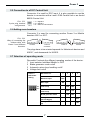
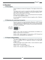
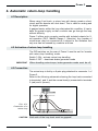
The Multiprotocol Power System
User’s Manual
Authors: Dr.-Ing. T. Vaupel, M. Berger
Translation: H. Schäfer
© Copyright Uhlenbrock Elektronik GmbH, Bottrop
2nd edition, June 2003
All rights reserved.
Reproduction - even partial - only under authorization.
Order number 60 562
Power 3
Contents
1. General
1.1 Description
1.2 Technical data
4
4
2. Setup
2.1
2.2
2.3
2.4
2.5
2.6
2.7
Connector definition
Plug wiring
Hookup of transformer, track, and return-loop
Connection to the Central Unit
Connection to a DCC Central Unit
Adding more boosters
Selection of operating mode
5
5
6
6
7
7
7
3. Booster
3.1
3.2
3.3
3.4
Description
Selection of control input connector
Output voltage limiting
DCC-operation without feedback to the Central Unit
8
8
8
9
4. Automatic return-loop handling
4.1 Description
4.2 Activation of return-loop handling
4.3 Hookup
10
10
10
5. Brake generator
5.1
5.2
5.3
5.4
5.5
Description
Selection of control input connector
Selection of operating mode
Connection
Brake generator operation without connection
to a Central Unit
6. Error indications
12
12
12
12
13
14
All brand names used are registered trademarks of the respective companies.
3
Power 3
1.
General
1.1 Description
Power 3 is a short-circuit-proof 3-ampere booster capable of handling different data transfer formats. It features a selectable automatic
return-loop handling, and its operation mode may be changed over
to work as a NMRA-compatible DCC brake generator.
The device is compatible with Central Units of Uhlenbrock, Arnold,
Lenz, and Märklin.
1.2 Technical data
Maximal input voltage
18 V AC
Maximal track current
3 amperes
All outputs are short-circuit proof.
Dimensions
180 x 136 x 80 mm (7 1/8 x 5 3/8 x 3 3/16 inches)
Required transformer capacity
52 - 70 VA
4
Power 3
2. Setup
In the following, the connectors of Power 3 are described together
with the necessary hookup instructions
2.1 Connector defintion
Pict. 2.11
Rear side showing
all connectors
2
1
2
3
4
5
3
4
6-pole male connector:
5-pole male connector:
5-pole male connector:
3-pole male connector:
4-pole DIP switch:
5
1
Transformer, track, return loop
Next booster or Central Unit
Next booster or Central Unit
DCC Central Unit
Operation mode
2.2 Plug wiring
The device comes with two plugs
for connection of transformer, track,
return loop, and DCC Central Unit.
Pict.2.21 The necessary wires have to be
Rear side showing inserted into their spring-loaded
all connectors terminals.
The terminal identfiers are shown
on the picture beside.
Pict. 2.22
Plug terminal
identifiers
The leads have to be made from
either solid or stranded wire of
0,25 mm2 (AWG 23/SWG 24). Insulation must be stripped off for 6 mm
(¼ in) at the end. Stranded wire
must either be twisted or tinned.
Use a small screwdriver of 2 mm
(0.08 in), insert it in the upper
opening and push down the spring
slightly. Slide the stripped end of the lead into the terminal. Release the screwdriver and the wire will be held firmly in position.
5
Power 3
2.3 Hookup of transformer and track
Transformer, track, and return-loop are all hooked up to connector
#1. The plug terminals are designated as follows:
123456
yellow
brown 16V~
Pict. 2.31
6-pole plug terminal
designations
brown
red
return-loop
brown
red
1
2
3
4
5
return-loop
return-loop
track feeder N digital (Märklin red)
track feeder S digital (Märklin brown)
16 V AC input - common (Märklin
brown)
6 16 V AC input - phase (Märklin yellow)
track
Transformer requirements
For trouble-free operation, the transformer must be able to supply
52 VA at 16 VAC minimally. Under full load, we recommend a 70 VA
transformer such as the Uhlenbrock type 20 070. The voltage
should not exceed 18 VAC. The transformer must be connected to
the terminals #5 (brown) and #6 (yellow) of the plug.
Pict. 2.32
2-rail hookup
Pict. 2.33
3-rail hookup
2-rail track
2-rail track is connected to terminals #3 and
#4 of the plug.
3-rail track
3-rail track (Märklin) is connected by inserting
the brown lead into terminal #4 and the red
lead (center conductor) into terminal #3.
2.4 Connection to the Central Unit
Either Intellibox or Märklin Central Unit may be used. Electrical
connection is achieved by a ribbon-cable supplied with Power 3.
Connector 2 of booster is linked to connector 5 of the Intellibox or
the booster connector of the Märklin Central Unit.
Pict. 2.41
Way of connecting
the ribbon-cable with
booster and different
Central Units
Power 3
Intellibox
or M 6021
Power 3
M 6020
The plugs have to be oriented upwards for Uhlenbrock devices and
M 6021, and downwards for M 6020.
6
Power 3
2.5 Connection to a DCC Central Unit
Connector 4 is used for DCC input. It is also possible to use the
booster in connection with a Lenz LZ100 Central Unit or an Arnold
86200 Central Unit.
Pict. 2.51
3-pole plug terminal
assignments
1 C = Signal N
2 D = Signal S
3 E = Short circuit indication
2.6 Adding more boosters
Connector 3 is used for connecting another Power 3 or Märklin
boosters 6015 or 6017.
Pict. 2.61
Way of connecting the
ribbon-cable with
Power 3 and different
boosters
Power 3
or M 6017
Power 3
M 6015
Power 3
The plugs have to be oriented upwards for Uhlenbrock devices and
M 6017, and downwards for M 6015.
2.7 Selection of operating mode
Dip-switch 5 selects the different operating modes of the device.
1
2
3
4
Input selector Intellibox-Märklin or DCC
Brake generator mode on/off
Automatic return-loop handling on/off
Voltage limit on/off
Power 3
DIP-switch
setting
ON
OFF
1 2 3 4
DIP-switch no.
1
2
3
Motorola input
OFF
DCC input
ON
Booster without
return-loop
OFF
OFF
Booster with
return-loop
OFF
ON
Break generator mode
ON
OFF
4
Voltage limit
(H0 and bigger)
OFF
Voltage limit max. 18 V
(N)
ON
7
Power 3
3. Booster
3.1 Description
Power 3 delivers a current of 3 amperes. The output is short-circuit
proof.
The device can be used in conjunction with different digital Central
Units. When used with an Intellibox, it will deliver Motorola, DCC,
and Selectrix data formats to the track.
When used with a Märklin, Lenz, or Arnold Central Unit it will transfer
the data format supplied by these.
It is not possible to operate the device together with a Selectrix
Central Unit.
3.2 Selection of control input connector
Power 3 may work on input provided by Motorola- or DCC Central
Units. Depending on the data format, these Central Units are jacked
to different connectors. The DIP-switch on the rear side of the device
must be set accordingly.
Pict. 3.21
DIP-switch
of Power 3
ON
OFF
1 2 3 4
Switch 1 OFF - when the device is connected to an Intellibox or a
Märklin Central Unit via connector 2.
Switch 1 ON - when the device is connected to a DCC Central Unit
(Lenz LZ100, Arnold 86200) via connector 4.
3.3 Output voltage limiting
The output voltage depends on the transformer used and the load
present. A standard 16 V AC transformer delivers a no-load peak
voltage of 22 V.
As this is too high for the smaller scales, it can be limited to a peak
value of 18 V for e.g. N scale.
Switch 4 OFF - no output voltage limit
Switch 4 ON - the peak voltage is limited to 18V
8
Power 3
3.4 DCC-operation without feedback to the Central Unit
If a booster is feeding a track sector and the short-circuit feedback
to the Central Unit is not desired, this booster must be connected
by the DCC-input. Only C and D terminals are used (refer to
connection of a DCC Central Unit)
In case of a short, the booster will cut the track power for 10 seconds.
If the short-circuit continues, it will cut it out for 10 seconds again.
IMPORTANT
If this mode is used in conjunction with an Intellibox, Selectrix
decoders cannot be operated in the sectors fed by this booster.
9
Power 3
4. Automatic return-loop handling
4.1 Description
When using 2-rail track, a return loop will always create a shortcircuit and the booster will shut down. This is valid for analog and
for digital operation.
A gapped sector within the loop eliminates this condition. It has to
have its special supply so that a vehicle can go through the loop
without difficulty.
Power 3 offers such a supply module with isolated outputs for 2rail operation (DCC, Märklin Gauge 1, Selectrix). Any number of
return-loops may be connected to it subject to the limitation that
only one can be crossed by a vehicle at a time.
4.2 Activation of return-loop handling
The DIP-switches on the rear of Power 3 must be set for ‘booster
with return-loop handling‘ mode.
Switch 3 ON - activate return-loop handling
Switch 2 OFF - deactivate brake generator mode
IMPORTANT
When handling return-loops, brake-generator mode must be off.
4.3 Connection
The return-loop is fed by a 6-pole plug attached to connector 1 of
Power 3.
Refer to the following schematic showing the loop track connected
to terminals 1 and 2, and the normal track(s) connected to terminals
3 (red) and 4 (brown).
123456
16V~
Loop track
Normal track
Pict. 4.31
Connection of a
return-loop
CAUTION
Both rails of the loop track must be gapped!
10
Power 3
IMPORTANT
Tracks immediately adjacent to the return-loop must be fed by the
booster that controls the loop.
As the loop control is activated by a vehicle crossing the gaps,
feeders from the booster running to loop and normal trackage
should be placed close to them.
11
Power 3
5. Break generator
5.1 Description
A brake generator takes care of the prototypical deceleration of
DCC-locos in front of a signal showing ‘danger’. The loco will slow
down according to the rate set in its decoder CV.
A particular ‘brake’ signal triggers this action. Moreover, a special
circuitry has to avoid short circuits between the braking section and
the remainder of the track when a vehicle crosses the gap.
The brake generator monitors every individual braking section. As
soon as a train is completely within the section, the brake generator
takes over.
5.2 Selection of control input connector
The Power 3’s data signal may derive from a Motorola- or a DCC
Central Unit. They are connected to different inputs depending on
the data format. Moreover, the DIP-switch on the booster’s rear
side must reflect this selection.
Switch 1 OFF - when the device is connected to an Intellibox or a
Märklin Central Unit via connector 2.
Switch 1 ON - when the device is connected to a DCC Central Unit
(Lenz LZ100, Arnold 86200) via connector 4.
5.3 Selection of operating mode
In order to use the Power 3 as a brake generator, the DIP-switches
on the rear side must be set accordingly.
Switch 2 ON - Brake generator mode on
Switch 3 OFF - Booster mode off
5.4 Connection
A section in front of a distant signal is subdivided into a running and
a braking sector. They are switched over to brake generator
operation by an occupancy detector as soon as the train enters the
braking sector. Therefore, the running sector must be made a trifle
longer than the longest train in order to avoid shorts.
The length of the braking sector must be chosen in such a way that
all locos with a set deceleration will come to a full stop within.
The changeover to braking can be achieved e.g. by occupancy
detector with relay, item #43 400.
The power supply can be provided by the Intellibox’s booster,
another Power 3 (item # 65 600), or a Märklin booster (6015 or 6017).
12
Power 3
S1
Direction
of travel
Central Unit
or booster
Pict. 5.41
Possible circuit
employing a GBM
occupancy detector
Break
generator
running sector
block section
Relay 2
Relay 1
AC
Track supply +/-
Monitored section
Track supply / AC
Switch S1 must be a NC type. It may be taken from the block signal
or a relay contact. Switching the signal to ‘proceed’ must open S1,
so that the occupancy detector (GBM) is not activated.
The whole block section is fed by a Central
Unit or a booster in this
case.
When the signal is set
to ‘danger’, S1 closes
and the occupancy
detector (e.g. GBM
43400) monitors the
braking sector.
As soon as a vehicle
enters it, the whole
block section’s supply
will be taken over by the
brake generator.
5.5 Brake generator operation without connection to a Central Unit
If the booster is used as a braking generator without short-circuit
feedback and control by the Central Unit, the operation mode has
to be set to brake generator and Motorola input. A cable connection
to the Central Unit is not needed in this case.
In case of a short, the booster will cut the track power for 10 seconds.
If the short-circuit continues, it will cut it out for 10 seconds again.
The braking sector cannot be switched off by the Central Unit.
13
Power 3
6. Error indications
Power 3 indicates errors and failures by different blinking sequences
of the red and green LEDs.
green LED on - red LED off
’go’-key depressed
Track voltage present (normal operation)
red LED on - green LED off
’stop’-key depressed
Track voltage cut by the Central Unit
green LED off - red LED flashing
Short circuit indication
LEDs flash alternatively red and green
Overheating, track voltage is off
LEDs flash alternatively one time red and two times green
No data input signal present
LEDs flash alternatively one time red and three times green
External voltage present at outputs when Power 3 is switched on
14
Power 3
HOTLINE
Any problems?
Please e-mail to
[email protected]
15